

Page 1

®
Page 2

Table of ConTenTs
Alternate Languages ........................................................................................................................3
Introduction ....................................................................................................................................3
ModelMatch/Binding ......................................................................................................................4
System Features ..............................................................................................................................4
Installing the Batteries .....................................................................................................................5
Charging .........................................................................................................................................5
Identifying Buttons, Switches and Controls .....................................................................................6
Steering Tension Adjustment ..........................................................................................................7
Binding ...........................................................................................................................................7
ModelMatch ....................................................................................................................................7
Failsafe ...........................................................................................................................................7
Binding a Receiver ..........................................................................................................................8
Receiver Compatibility ....................................................................................................................9
Receiver Connection and Installation ..............................................................................................9
Changing to Left-Handed Configuration .......................................................................................10
Using the Rolling Selector ............................................................................................................12
Main Screen ..................................................................................................................................13
List ................................................................................................................................................13
Model ...........................................................................................................................................14
Model Select .................................................................................................................................14
Model Name .................................................................................................................................15
Model Copy ..................................................................................................................................16
Travel ............................................................................................................................................17
Steering Rate .................................................................................................................................18
Exponential ...................................................................................................................................19
Reverse .........................................................................................................................................20
Sub Trim .......................................................................................................................................20
Timer.............................................................................................................................................21
Bind ..............................................................................................................................................22
ModelMatch ..................................................................................................................................22
Failsafe .........................................................................................................................................23
Frame Rate ....................................................................................................................................24
Mixing ..........................................................................................................................................25
Trim Step.......................................................................................................................................26
Reset .............................................................................................................................................26
Monitor .........................................................................................................................................28
System ..........................................................................................................................................28
Switch Select ................................................................................................................................29
User Name ....................................................................................................................................29
General Notes ...............................................................................................................................30
Warranty and User Information .....................................................................................................30
Operating and Programming Notes: ..............................................................................................35
2 SPEKTRUM DX3R PROGRAMMING GUIDE
Page 3
alTernaTe languages
ITALIAN: Per la versione italiana di questo
manuale vi preghiamo di visitare il
sito www.spektrumrc.com
FRENCH: Pour consulter ce manuel en
français, visiter le site www.
spektrumrc.com
GERMAN: Zur Ansicht der Bedienunsanleitung
in den Deutsch besuchen Sie bitte
www.spektrumrc.com
InTroduCTIon
SPANISH: Para ver este manual en Español
entra en www.spektrumrc.com
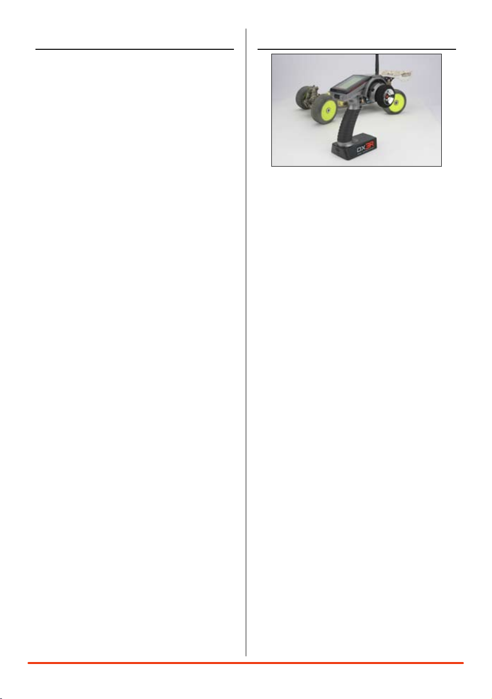
Spektrum’s DX3R was designed by top level
racers to be the ultimate uncompromising racing
radio. Featuring DSM2™ next generation 2.4GHz
technology, the DX3R offers the fastest possible
response rate that’s up to 4 times faster than
conventional 75 and 27MHz radio systems.
Sophisticated software combined with an easyto-use one-touch roller makes programming
quick and easy. User-programmable switches and
buttons allow functions like throttle trim, steering
rate, auxiliary channel functions, brakes, timers,
steering rate override, and even throttle and steering
exponential adjustments to be assigned to any of
six programmable switch/ button positions. Plus
the DX3R can easily be converted for right- or lefthanded drivers.
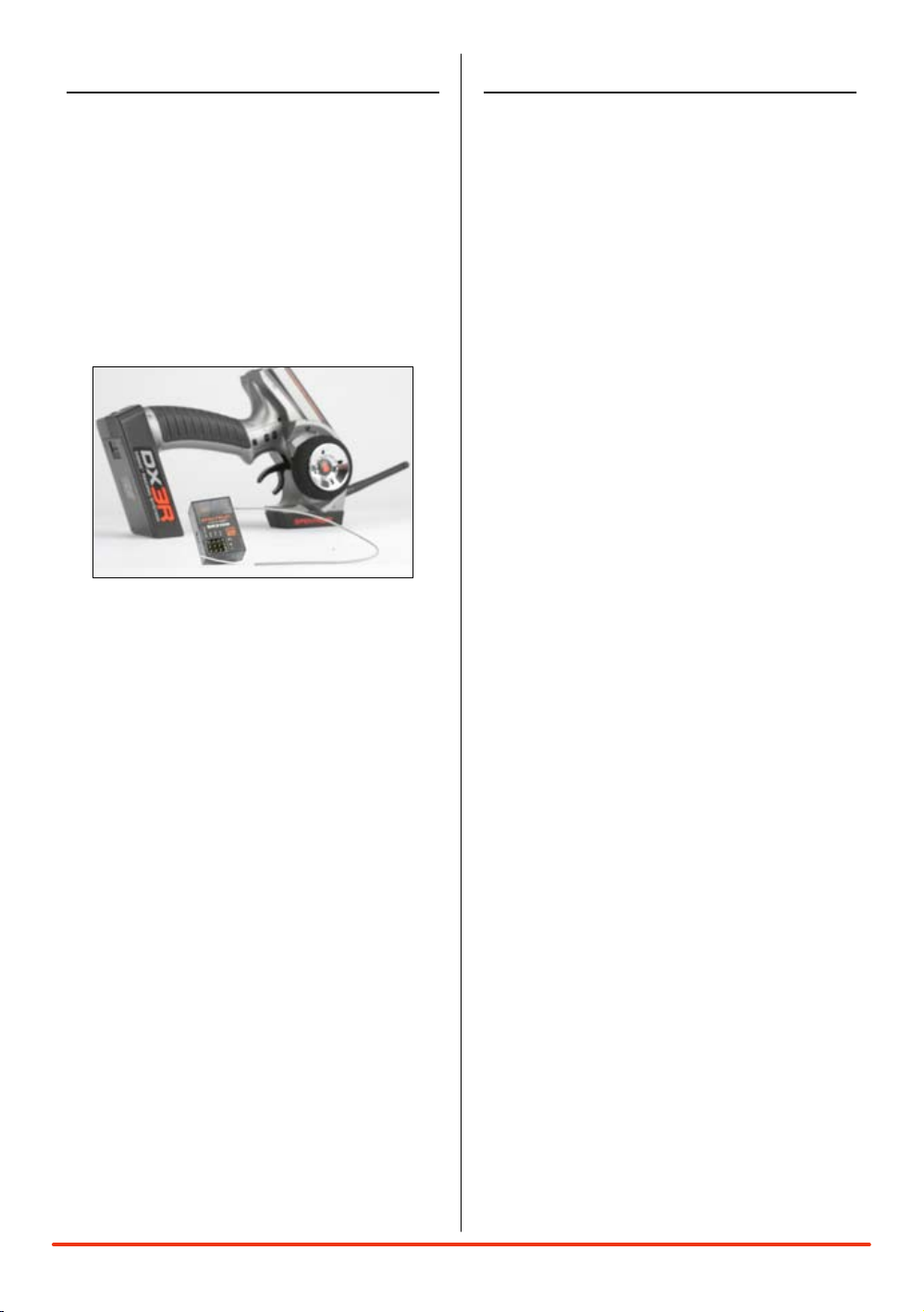
Spektrum™ technology offers a bulletproof radio
link that’s immune to internal (noisy motors/ESC’s,
etc.) and external interfering sources. No longer
will you have to wait for a frequency or worry about
someone else being on the same channel. With
Spektrum, when you’re ready to race there’s nothing
stopping you!
3SPEKTRUM DX3R PROGRAMMING GUIDE
Page 4
ModelMaTCh/bIndIng
The DX3R features ModelMatch™ (patent pending).
ModelMatch prevents a model from being operated
using the wrong model memory. If the wrong model
memory is selected, the receiver simply won’t
respond to the transmitter preventing driving the car
using the wrong model memory.
It’s necessary to program the receiver to a specific
model memory (called binding) so that the receiver
will only recognize and respond to that specific
model memory. See Pages 22 and 23 for specific
details on Binding and ModelMatch.
sysTeM feaTures
• DSM22.4GHzsecond-generationtechnologyoffers
the fastest possible response rate
• One-touch,easy-to-useprogramming
• Sixassignableswitchesallowfunctionsliketimers,
on-the-fly expo adjustment, throttle and brake
trimmers, steering rate, steering override, etc. to be
freely assigned to your preference
• Right-andleft-handcompatible
• ProgrammableSteeringRateoverride
• On-the-ythrottleandsteeringexponential
adjustments
• Allswitchescanbeprogrammedtooperateineither
direction
• Threeprogrammabletimers:Up,Downand
Integrated
• 128x64highresolutionDotMatrixscreen
• 30-modelmemory
• GraphicallysupportedTravelAdjustandExpocurves
• Selectableframeratesof5.5,11and16.5ms
allow fastest possible response with total servo
compatibility
• Twoprogrammablemixers
• Adjustabletrimsteps
• Digitalservomonitordisplaysgraphicanddigital
servo positions
• Displaysusernameandmodelname
• Calibrationscreenallowsrecalibrationofsteering
and throttle positions for the ultimate in accuracy
4 SPEKTRUM DX3R PROGRAMMING GUIDE
Page 5
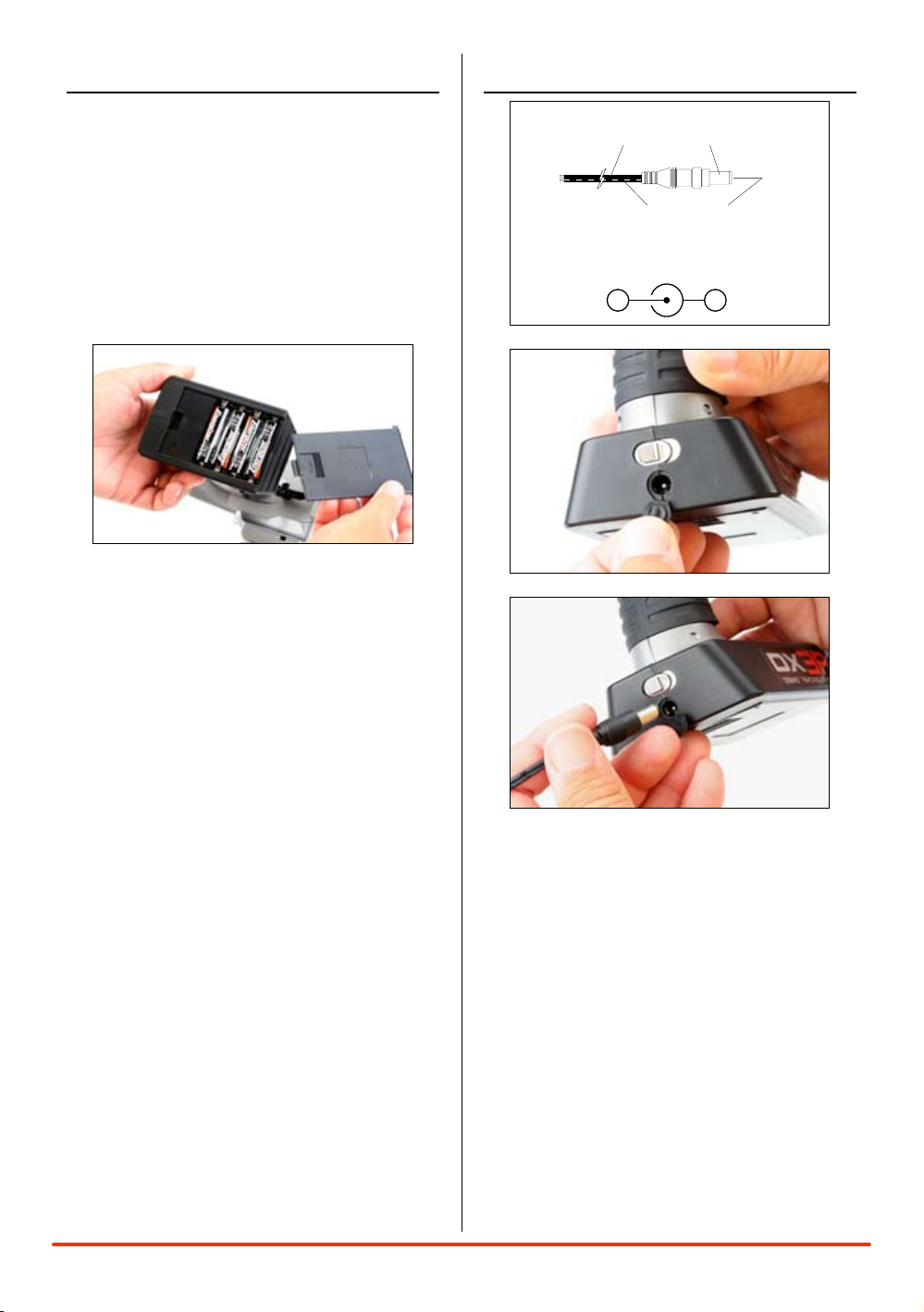
InsTallIng The baTTerIes
Charger Pigtail for Transmitter
Spektrum Transmitter Charge Jack Polarity
BLACK TO POSITIVE
BLACK W/WHITE STRIPE TO NEGATIVE
-
+
The transmitter requires 4 AA batteries: brand
name alkaline AA’s providing over 15 hours of run
time. Many racers prefer alkaline batteries over
rechargeable batteries, finding it more convenient
to simply replace the batteries when depleted rather
than taking the time to recharge.
Optional NiCd or NiMH 1.2-volt AA rechargeable
batteries can also be used. A charge jack located
below the on/off switch is provided for convenient
recharging.
Remove the battery door and install 4 AA batteries,
noting that the polarity of each corresponds with
the diagram in the battery holder. Replace the
battery door.
ChargIng
A charging jack is located just below the on/ off
switch. If rechargeable batteries are used, they can
be conveniently charged without removing them
from the transmitter using the charge jack.
IMPORTANT: All Spektrum charge jacks are center
pin negative. This is the opposite of many chargers.
Before using a charger, make sure the connector
is center pin negative. This can be done using a
voltmeter. Also, unlike conventional radio systems
that use 8 cells to power the transmitter, the DX3R
uses 4 cells. This is due to the electronics being
more efficient. When charging, be sure to use a
charger designed for 4 cells (4.8-volt battery pack)
when charging the transmitter. Many racers simply
make a harness and use the same charger used to
charge their car packs but turn the current rate down
to 1 to 2 amps.
5SPEKTRUM DX3R PROGRAMMING GUIDE
Page 6
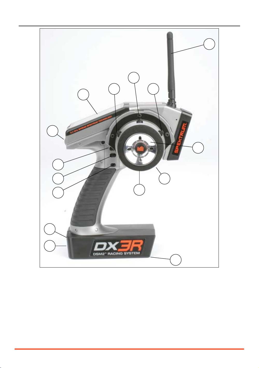
IdenTIfyIng buTTons, swITChes and ConTrols
1
2
3
4
14
13
5
6
7
8
9
15
10
11
12
1: Antenna 2: LCD Screen 3: Switch D/Steering Trim
4: Switch E/Brake 5: Button F/Timer 6: Charge Jack
7: Switch A/Throttle Trim 8: Switch B/Steering Trim 9: Switch C/Aux 3 Linear
10: Rolling Selector 11: Battery Door 12: On/Off Switch
13: Throttle Trigger 14: Steering Wheel 15: Steering Tension Adjustment
6 SPEKTRUM DX3R PROGRAMMING GUIDE
Page 7

Note: The switches listed above are the factory
default functions assigned to each switch.
Each switch can be programmed to one of ten
functions including:
• Inhibit
• Aux3-channel,3-position(forreverse,neutraland
forward transmissions)
• Aux3-channel,2-position(forreverseandforward
transmissions)
• Aux3-channel,linear(formixturecontrol)
• Brake(adjustablefullbrakeposition)
• Throttleexponential(allowson-the-ythrottle
expo adjustments)
• Throttletrim(coastbrakeposition)
• Steeringoverride(overridessteeringrate
when activated)
• Steeringexponential(allowson-the-y
steering adjustments)
• SteeringRate
• SteeringTrim
See pages 30 for System info and assignments for
more details.
sTeerIng TensIon adjusTMenT
Steering tension is adjusted via the recessed
screw located below the steering wheel (see
Steering Tension Adjustment on the previous page).
Using a small Phillips screwdriver, turning the
screw clockwise increases steering tension while
turning the screw counterclockwise reduces
steering tension.
ModelMaTCh
The DX3R features patented ModelMatch technology
that prevents operating a model using the wrong
model memory. During the binding process, the
receiver actually stores the code that is assigned
to the specific model that is currently selected in
the transmitter. For example: if the model that is
selected in the transmitter is model #3, when a
receiver is bound to that transmitter, the receiver will
only operate when model #3 is selected. If another
model memory is selected (model #5 for example)
the receiver will not connect. If model three is
again selected in the transmitter, the receiver bound
to model #3 will connect. ModelMatch prevents
operating a model using the wrong model memory.
faIlsafe
Failsafe positions are also set during binding. In
the unlikely event that the radio link is lost during
use, the receiver will drive the servos to their
preprogrammed failsafe positions (normally full
brakes and straight steering). If the receiver is turned
on prior to turning on the transmitter, the receiver
will enter the failsafe mode, driving the servos to
their preset failsafe positions. When the transmitter
is turned on, normal control is resumed. Failsafe
servo positions are set during binding (see binding
a receiver below).
bIndIng
In order to operate, the receiver must be bound to
the transmitter. Binding is the process of teaching
the receiver the specific transmitter’s code called
GUID (Globally Unique Identifier). When a receiver is
bound to a transmitter/ model memory, the receiver
will only respond to that specific transmitter/ model
memory (see ModelMatch).
7SPEKTRUM DX3R PROGRAMMING GUIDE
Page 8
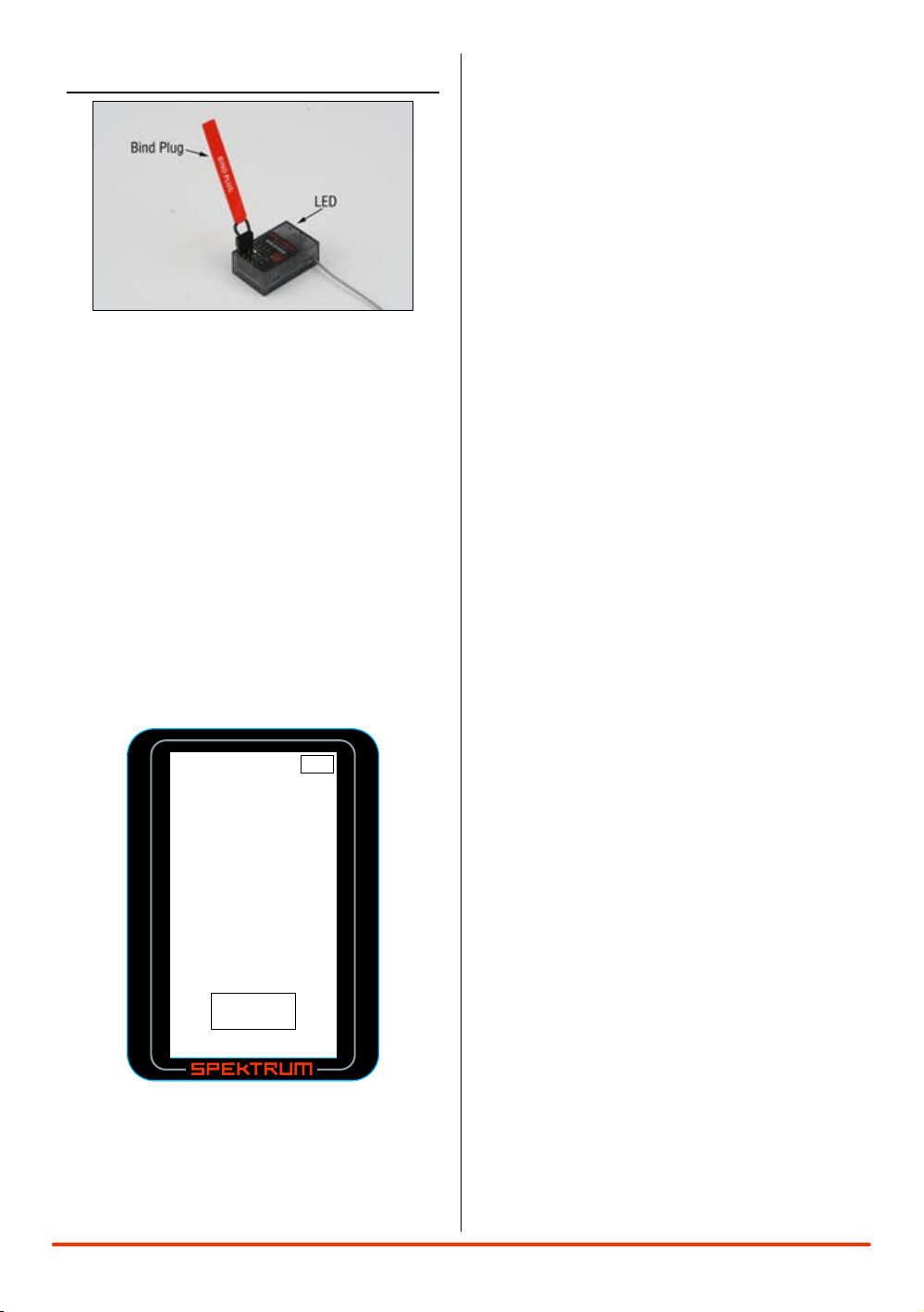
bIndIng a reCeIver
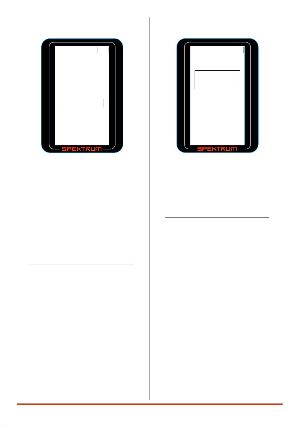
User Na m e
01: Mod e l 0 1
Bi n d
BI ND
Pla c e the RX
int o b ind
mod e f irst .
≤
7. With the steering wheel, throttle stick and Aux channel
(if applicable) in the desired preset failsafe positions,
press the roller to initiate the bind process and to store
the failsafe positions. BIND will flash for a few seconds
then the transmitter will beep, indicating the process
is complete. The LED on the receiver should now be
solid, indicating a successful bind has taken place.
8. Remove the bind plug and store it in a
convenient place.
Note: The SR3100 features DSM2 secondgeneration technology and is only compatible
with transmitters that utilize DSM2 protocol (Like
the DX3R) DSM1 transmitters will not operate the
SR3100 receiver.
1. With the receiver off, insert the bind plug into the Batt/
Bind port in the receiver.
2. Power the receiver. The amber LED will flash
continuously, indicating that the receiver is in bind
mode.
3. Turn on the transmitter and make sure the transmitter is
in the desired model number that you intend to use.
4. Press the rolling selector to access the List screen.
5. Rotate the roller to highlight the Bind screen and press
the roller to access this screen.
Note: The only time it’s necessary to do a
rebind is if different failsafe positions are
desired or if the receiver is to be bound to a
different model memory.
Note: Some Spektrum receivers like the
AR3000 use a bind button rather than a bind
plug. The binding process is the same with
this receiver, however, instead of inserting the
plug before powering up the receiver, press
and hold the bind button while powering up
the receiver to enter the bind mode.
6. Rotate the roller to highlight BIND.
8 SPEKTRUM DX3R PROGRAMMING GUIDE
Page 9

reCeIver CoMpaTIbIlITy
7.2V Battery
To Motor
Electronic
Speed Control
Receiver
Servo
SR3100
DSM
AUX
THR
STR
BAT/TEL
2.4GHz DSM²
+
−
Battery
Switch
Servos
Receiver
SR3100
DSM
AUX
THR
STR
BAT/TEL
2.4GHz DSM²
+
−
The DX3R features DSM2 technology but is also
compatible with most DSM1 Spektrum surface
receivers. When the fastest response rate is desired,
using the system with a DSM2 receiver like the
AR3100 is recommended as this combination gives
the lowest possible latency/ quickest response rate.
During the binding process the transmitter actually
“learns” the receiver type (DSM1 or DSM2) and
configures itself to transmit that protocol.
CoMpaTIble spekTruM reCeIvers
DSM2
SR3100- 3-channel DSM2 Pro- SPMSR3100
DSM1
SR3000- 3-channel Standard- SPM1200
SR3001- 3-channel Pro-Model- SPM1205
SR3500- 3-channel Micro Race- SPM1210
Note: The SR3000HRS model # SPM1202
receiver is designed to be used with Futaba’s
HRS compatible module system only and is
not compatible with the DX3R.
reCeIver ConneCTIon
and InsTallaTIon
Typical Electric Installation
Typical Gas Installation
9SPEKTRUM DX3R PROGRAMMING GUIDE
Page 10
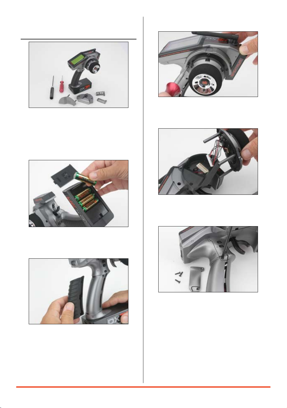
ChangIng To
lefT-handed ConfIguraTIon
The DX3R is shipped set up for right-handed use but
can easily be switched to left-handed configuration.
All the parts necessary to convert to left-handed,
including the grip plates, the back cover and the
front shell are included. A 3/32-inch hex wrench and
a small Phillips screwdriver will be needed.
3. Use a 3/32inch hex wrench remove the three
screws on the front of the steering housing
as shown.
1. Remove the batteries from the transmitter. This
prevents the possibility of accidentally causing a
short during the conversion.
2. Carefully remove the grip cover by prying
with your fingers at the forward edge of the
rubber grip.
4. Carefully remove the steering mechanism
and unplug the steering connector. Also
remove the backplate.
5. Using a small Phillips screwdriver, remove the
four Phillips screws (two per side) that fasten the
grip plates in place and remove the grip plate that
doesn’t have the buttons attached.
10 SPEKTRUM DX3R PROGRAMMING GUIDE
Page 11
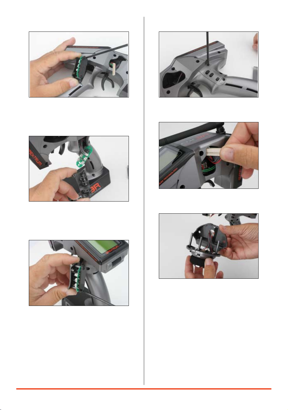
6. Carefully pull out the grip plate that contains
buttons D, E and F. Use a Phillips screwdriver
remove the PC board and backplate from the grip
plate. Note the positions of the three buttons.
7. Transfer the three buttons (D,E and F) to the other
“handed” grip plate noting that the buttons fit in
a specific direction such that they fit the external
contour of the grip plate.
9. Place both grip plates in place and fasten them
using four Phillips screws (two per side).
10. Push the steering wheel connector through the
transmitter case to the opposite side.
8. Carefully screw the PC board and backplate
in place and test that all buttons are
depressing properly.
11. Select the opposite “handed” steering shell and
pass the steering wheel mechanism connector
through the hole in the shell.
11SPEKTRUM DX3R PROGRAMMING GUIDE
Page 12

usIng The rollIng seleCTor
12. Connect the steering wheel mechanism connector
to the connector from the transmitter being sure
the connection is tight. Note correct polarity.
13. Fit the other handed backplate in place and
secure the steering wheel assembly in place
using the three long cap head screws.
The Rolling Selector is pressed to access functions
and rolled to selected specific features or to change
setting or values. Pressing and holding the rolling
selector for more that 3 seconds returns the display
to the main screen.
The DX3R features one-touch programming
utilizing a Rolling Selector. The Rolling Selector
has three functions:
1: Pressing the Rolling Selector - enters the
selected function
2: Rolling the Rolling Selector - highlights function or
changes settings and values when selected.
3: Pressing and holding the rolling selector for more
than 3 seconds from any screen - returns the display
to the Main Screen.
Programming is very intuitive and always starts
with a press, then a roll, then a press, roll and
so on. Most find that within a few minutes they’re
able to easily program their car without reading
the instructions, however, to realize the full benefit
of the programming it’s recommended that the
manual be read.
Most racers find it’s most convenient to use their
thumb when making programming changes, as
this allows for one-handed programming, even
allowing the car to be run in one hand while making
14. Fit the grip in place and reinstall the batteries.
Note that the buttons D and E now work in
reverse. It will be necessary to change the
direction of these switches in the System menu
(see page 29)
12 SPEKTRUM DX3R PROGRAMMING GUIDE
programming adjustments in the other.
Note: Each individual page from this point
is dedicated to a single specific programming
function.
Page 13

MaIn sCreen
Ra cer X
01 : L osi E igh t
In t 1: 47: 30
Dn Tm r 05 :00
S/ R 7 5%
4.7
vo lt s
Tr im
St
Th
BR
-1 2
+0
+1 04
1
2
3
4
5
6
7
8
9
Li s t
Mod e l
Tra v e l
Ste e r Rat e
Exp o n e nti a l
Rev e r s e
Sub T r im
Tim e r
Bin d
Fra m e Rat e
Mai n
lIsT
The information displayed on the screen is as follows:
1: Timer A 5: Brake Trim
2: Timer B 6: Steering Rate
3: Steering Trim 7: User Name
4: Throttle Trim 8: Model number and name
9: Transmitter (Tx) voltage (flashes and alarm sounds
when low battery is reached)
The main screen displays pertinent information
about the selected model like trim and steering
rate positions, timers, the model selected, battery
voltage, etc. and it’s recommended that during
driving/ racing the main screen be displayed.
To aCCess The MaIn sCreen:
Any time the transmitter is turned on the main
screen will appear.
From the List screen, the first function at the top of
the List screen is Main. Using the roller, highlight
the Main function and press the roller to access the
Main screen.
From any screen, pressing and holding the roller for
more than three seconds will return the display to
the Main screen.
Note: When the battery voltage drops below
the preset value in the System function (preset
to 4.0 volts), an alarm will sound and the
voltage reading will flash.
The List screen displays all the available
functions. The desired function can be accessed
by highlighting the desired function using the
roller and when highlighted, press the roller to
enter the function.
To aCCess The lIsT sCreen:
From the main screen, pressing the roller will access
the List screen
From any other screen, an arrow is located at
the top of each of the programming screens. This
is a back arrow and highlighting this arrow with the
roller and then pressing the roller will return to the
List screen.
13SPEKTRUM DX3R PROGRAMMING GUIDE
Page 14

01: Mod e l 0 1
Mo d e l
Select:
Name:
Model 0 1
◊
Copy To :
02: Mod e l 0 2
≤
Model
01: Mod e l 0 1
Mo d e l
Select:
Name:
Model 0 1
◊
Copy To :
02: Mod e l 0 2
≤
Model seleCT
The Model screen offers three functions:
Model Select: Allows the selection of one of thirty
model memories. This allows you to
store and select up to thirty models.
Model Name: Allows the selected model to
be given a name with up to ten
characters.
Model Copy: Allows a model memory to be
copied internally to a different model
memory (i.e. model one (01) can be
copied to model thirty (30)).
To aCCess The
Model seleCT funCTIon:
In the Model screen use the roller to highlight
the Select function. A box will surround the
Select function.
Press the roller to access the select function.
The box will now be flashing, indicating the
Select function is active.
Use the roller to select the desired model memory
(models 01 thru 30).
To return to the Main screen, press and hold the
roller for more than three seconds.
14 SPEKTRUM DX3R PROGRAMMING GUIDE
Page 15

Model naMe
Mo d e l
Na m e
Name:
Model 0 1
◊
≤
To aCCess The
Model naMe funCTIon:
In the Model screen, use the roller to highlight
the Name function. A box will surround the Select
function.
Press the roller to access the Name function. The
above screen will appear.
Use the roller to select the desired model name
character position by placing the cursor below the
desired position.
Press the roller to access that character or number;
then use the roller to change to the desired letter or
number.
Pressing the roller will allow the cursor to be
repositioned to the next field.
To return to the Main screen, press and hold the
roller for more than three seconds. You can also use
the roller to select the back arrow.
15SPEKTRUM DX3R PROGRAMMING GUIDE
Page 16

Model Copy
01: Mod e l 0 1
Mo d e l
Select:
Name:
Model 0 1
◊
Copy To :
02: Mod e l 0 2
≤
Co n f irm
Cop y
01: M ode l 0 1
to
02: M ode l 0 2
NO
YES
≤
To aCCess The
Model Copy funCTIon:
In the Model screen use the roller to highlight
the Copy To function. A box will surround the
Copy To function.
Press the roller to access the Copy To function.
The box will now be flashing, indicating the Copy To
function has been selected.
Use the roller to select the desired model that you
choose to copy to (models 01 thru 30).
When the desired model that you intend to copy to
is selected, press the roller. The screen will appear
as follows:
If the selected model is correct, use the roller to
highlight YES and press the roller to copy from the
current model to the selected model.
Note: The model memory of the selected
model will be replaced with the current model’s
model memory, thus erasing the copy to
model’s memory.
To return to the Main screen, press and hold the
roller for more than three seconds.
16 SPEKTRUM DX3R PROGRAMMING GUIDE
Page 17

Travel
User Na m e
01: Mod e l 0 1
L 100%
R 100%
H 100%
L 100%
H 100%
L 100%
ST
TH
AX
Tr a v el
≤
01: Mod e l 0 1
Steerin g
100% 1 0 0 %
Tr a v el
≤
The Travel screen (sometimes referred to as travel
adjust or end points) allows independent travel
adjustment of the servo throw in each direction of
all three channels (steering, throttle and auxiliary).
A graphic illustration displays the effect of travel
adjust.
To aCCess The Travel funCTIon:
From the list screen rotate the roller to highlight the
Travel function.
Press the roller to enter the Travel function. The
Travel screen will be displayed as shown above.
Rotate the roller to highlight the desired channel that
you wish to adjust the travel.
ST= Steering
TH= Throttle and brake
AX= Auxiliary channel 3
Press the roller to enter the highlighted channel’s
travel function (see monitor Page 28.)
Rotate the roller to highlight the values at the
bottom of the screen; then press the roller to
select the values.
Rotating the roller will now adjust both the right and
left values simultaneously. If you desire to adjust
the right or left directions independently, then move
the corresponding channel’s wheel, throttle stick or
trigger. The trimmer that the Aux channel is assigned
to and that value alone will be highlighted (i.e.
turning the steering wheel to the right will highlight
the right value only and subsequent adjustment will
effect the right travel only).
Note: The DX3R features “sticky gooey.”
When the corresponding channel is moved
in the desired position as illustrated above
and released, the value on that side remains
highlighted. Moving the channel in the
opposite direction will then highlight the
opposite direction’s value. This allows
convenient independent travel adjustments
without having to hold the wheel or trigger in
the desired position. To highlight both values
again after moving the wheel in one direction,
simply press the roller once with the wheel
centered and both values will be highlighted.
17SPEKTRUM DX3R PROGRAMMING GUIDE
Page 18

sTeerIng raTe
01: Mod e l 0 1
St e e r R a t e
User Na m e
S/R
100%
S/R Ove r r i d e
INHIBIT
≤
To aCCess The
sTeerIng raTe funCTIon:
In the List screen use the roller to highlight the
Steering Rate function.
Press the roller to access the Steering Rate function.
The above screen will appear.
Use the roller to select the S/R function or the S/R
Override function by placing the box around the
desired function.
Press the roller to access S/R or S/R Override;
then use the roller to change to the desired
Steering rate value.
To return to the main screen press and hold the
roller for more than three seconds.
Steering rate (also know as dual rate) allows onthe-fly steering travel adjustments to be made using
any of the programmable grip trimmers (A,B,C,D, or
E). The Steering Rate screen also offers a Steering
override function that allows a second steering rate
(normally 100%) to be accessed at the touch of
a button or trimmer. This is especially helpful for
oval racers that program minimal steering throw
to desensitize steering during racing but require
maximum steering angle to drive out of a crash or
get turned around on the track. The user name and
model number and model name are also displayed
in this screen.
Note: An adjustable S/R rate can be assigned
to any of the trimmers (A,B,C,D and E) and is
defaulted to trimmer D. This trimmer works in
unison with the S/R Rate screen and the value
can be adjusted from either the screen or from
the programmable trimmer. If it’s desired to
not have an on-the-fly adjustable Steering Rate
the S/R trimmer can be inhibited. See System
function under switch selection on page 29 for
more details.
Note: In order for the S/R Override to operate
it must be assigned to a switch or trimmer. The
default position for this function is inhibited.
To activate the S/R rate, it’s necessary to
program this function to the desired switch or
trimmer in the System function screen under
Switch. See page 29.
18 SPEKTRUM DX3R PROGRAMMING GUIDE
Page 19

exponenTIal
User Na m e
01: Mod e l 0 1
L 0 %
R 0 %
H 0 %
L 0 %
H 0 %
L 0 %
ST
TH
AX
Ex p o
≤
01: Mod e l 0 1
Steerin g
0% 0%
Ex p o
≤
Exponential is used to affect the response rate
of the steering, throttle and/ or brake. Typically
positive Exponential is used for steering, reducing
steering sensitivity around neutral, making it
easier to drive the car at high speeds in a straight
line but exponential still allows for the maximum
turning radius.
The DX3R’s Exponential function (Expo for short)
allows independent Expo values in each direction
of all three channels (steering, throttle and
auxiliary). A graphic illustration displays the effect
of exponential adjustment.
To aCCess The
exponenTIal funCTIon:
From the List screen rotate the roller to highlight the
Exponential function.
Press the roller to enter the Exponential function.
The Expo screen will be displayed as shown above.
Rotate the roller to highlight the desired channel that
you wish to adjust the travel.
ST= Steering
TH= Throttle and brake
AX= Auxiliary channel 3
Press the roller to enter the highlighted channel’s
Expo function.
Rotate the roller to highlight the values at the
bottom of the screen; then press the roller to
select the values.
Rotating the roller will now adjust both the right and
left values simultaneously. If you desire to adjust
the right or left Expo values independently, move
the corresponding channel’s wheel, throttle stick or
trigger the trimmer that the Aux channel is assigned
to, and that value alone will be highlighted (i.e.
turning the steering wheel to the right will highlight
the right value only and subsequent adjustment will
affect the right travel only).
Note: Positive and negative Expo values are
available. A positive Expo value results in the
center being less sensitive (desirable most of
the time) while a negative value increases the
sensitivity around center (normally not used).
Note: The DX3R features “sticky gooey.”
When the corresponding channel is moved
in the desired direction as illustrated
above and released, the value on that side
remains highlighted. Moving the channel
in the opposite direction will then highlight
the opposite value direction. This allows
convenient independent exponential
adjustments without having to hold the wheel
or stick in the desired position. To highlight
both values again after moving the wheel in
one direction, simply press the roller once
with the trigger centered and both values will
be highlighted.
19SPEKTRUM DX3R PROGRAMMING GUIDE
Page 20

reverse
User Na m e
01: Mod e l 0 1
ST
TH
AX
Re v e rse
REV NO R
≤
User Na m e
01: Mod e l 0 1
ST 0
TH 0
AX 0
Su b Tri m
≤
sub TrIM
The Reverse function (also know as servo reverse)
establishes the servo’s direction relative to the
channels input (i.e. a right steering input should
result in a right steering angle at the car). Reverse
is available on all three channels and is normally
the first function that is checked and adjusted
during programming.
The user name and model number and model name
are also displayed in this screen.
To aCCess The reverse funCTIon:
In the List screen use the roller to highlight the
Reverse function.
Press the roller to access the Reverse function. The
above screen will appear.
Use the roller to select the desired channel that you
wish to reverse.
ST=Steering
TH=Throttle
AX= Auxiliary
Press the roller to highlight that channel and the
surrounding box will flash; then use the roller to
change to the desired servo direction (REV or NOR).
To return to the Main screen, press and hold the
roller for more than three seconds.
The Sub Trim function is normally used to correct for
minor angular inaccuracies that occur when placing
the servo horn on the servo. In many cases, the
servo horn is not exactly perpendicular to the servo
(or in the exact optimum desired position). Minor
sub trim values can be used to correct this offset
inaccuracy, however, it’s important to understand that
large sub trim values can limit the total throw of the
servo in that direction so small sub trim values only
are recommended.
The user name, model number and model name are
also displayed in this screen.
To aCCess The sub TrIM funCTIon:
In the List screen use the roller to highlight the Sub
Trim function.
Press the roller to access the Sub Trim function. The
above screen will appear.
Use the roller to select the desired channel that you
wish to reverse.
ST= Steering
TH= Throttle
AX= Auxiliary
Press the roller to highlight that channel and the
surrounding box will flash; then rotate the roller to
adjust the value and direction of the sub trim.
To return to the Main screen press and hold the
roller for more than three seconds.
20 SPEKTRUM DX3R PROGRAMMING GUIDE
Page 21

TIMer
User Na m e
01: Mod e l 0 1
Ti m e r
Int e rn al R eset
Int 0:08 : 19
Int 0:08 : 18
Tim e r A:
Dn T mr 05 : 00
Tim e r B:
≤
Down timer:
Can be programmed for up to 99 minutes and 99
seconds in one-second increments. Normally this
timer is programmed for the length of the race
with electrics and is defaulted to 5:00 minutes, or
the duration of the fuel tank in gas, warning the
driver that it’s time to pit and refuel. The Down
timer is started via a selectable programmable
switch. When the down timer expires, an alarm
will sound and the timer will begin to count up.
To pause the Down timer, press the button/switch
that the timer is programmed to. To reset the Down
timer to its preprogrammed value, press and hold
the programmed button for more than 3 seconds.
Timer B is defaulted to the Down timer, the time is
defaulted to 5:00 minutes and button F is defaulted
to actuate the down timer.
The DX3R offers three types of timers:
Internal timer:
Automatically records the time that the transmitter is
turned on. Timer A is defaulted to the internal timer.
Up timer:
The Up Timer is triggered via a selectable button/
switch and counts up from 00:00 seconds,
functioning as a stopwatch. It is useful for timing a
fuel run to determine fuel mileage/ pit stop strategy
or, for electrics, to time the run time of a pack to
determine gear ratio and setup information. To pause
the Up timer, press the button/switch that the timer
is programmed to. To reset the UP timer to 00:00,
press and hold the programmed button for more
than 3 seconds.
Two of the three timers can be selected and
displayed on the main screen. The user name and
model number and model name are also displayed
in this screen.
To aCCess The TIMer funCTIon:
From the List screen rotate the roller to highlight the
Timer function.
Press the roller to enter the Timer function. The
Timer screen will be displayed as shown above.
Rotate the roller to highlight the desired Timer that
you choose to program (Timer A or Timer B).
Press the roller to enter the highlighted Timer
function.
Rotate the roller to select:
Int- Internal
Dn Tmr- Down Timer
Up Tmr- Up Timer
Note: If Down timer is selected, pressing the
roller again will allow the time to be changed
by rotating the roller.
To reset the internal timer, rotate the roller to
highlight Internal Reset then press the roller to reset
the internal timer to 0:00:00.
See System on page 28 for details on programming
the timers to various buttons and switches.
21SPEKTRUM DX3R PROGRAMMING GUIDE
Page 22

bInd
User Na m e
01: Mod e l 0 1
Bi n d
BI ND
Pla c e the RX
int o b ind
mod e f irst .
≤
Binding is the process of teaching the receiver the
specific transmitter’s code called GUID (Globally
Unique Identifier) and store failsafe values . When a
receiver is bound to a transmitter/ model memory,
the receiver will only respond to that specific
transmitter/ model memory (see ModelMatch
below). It’s also important to understand that during
the binding process the transmitter is learning the
type of receiver that it’s being bound to, and the
transmitter configures itself to transmit in DSM1 or
DSM2 protocol depending on the type of receiver
that it’s being bound to. Note that the DX3R stores
this information for each model memory and recalls
the proper protocol when that model is selected. See
ModelMatch below.
Note: If a receiver is not bound to a specific
model memory, it will not operate.
ModelMaTCh
The DX3R features patented ModelMatch technology
that prevents operating a model using the wrong
model memory. During the binding process, the
receiver actually stores the code that is assigned
to the specific model that is currently selected in
the transmitter. For example: if the model that is
selected in the transmitter is model #3, when a
receiver is bound to that transmitter, the receiver will
only operate when model #3 is selected. If another
model memory is selected (model #5 for example)
the receiver will not connect. If model three is
again selected in the transmitter, the receiver bound
to model #3 will connect. ModelMatch prevents
operating a model using the wrong model memory.
bIndIng a reCeIver
Note: The SR3100 features DSM2 secondgeneration technology and is only compatible
with transmitters that utilize DSM2 protocol
(like the DX3R). DSM1 transmitters will not
use the SR3100 receiver.
1. With the receiver off insert the bind plug into the Batt/
Bind port in the receiver.
2. Power the receiver. The amber LED will flash
continuously, indicating that the receiver is in
bind mode.
3. Turn on the transmitter and make sure the transmitter is
in the desired model number that you intend to use.
4. Press the rolling selector to access the List screen.
5. Rotate the roller to highlight the Bind screen and press
the roller to access this screen.
22 SPEKTRUM DX3R PROGRAMMING GUIDE
Page 23

User Na m e
01: Mod e l 0 1
Bi n d
BI ND
Pla c e the RX
int o b ind
mod e f irst .
≤
6. Rotate the roller to highlight BIND
7. With the steering wheel, throttle stick and Aux
channel (if applicable) in the desired preset failsafe
positions, press the roller to initiate the bind process
and to store the failsafe positions. BIND will flash for
a few seconds; then the transmitter will beep,
indicating the process is complete. The LED on
the receiver should now be solid, indicating a
successful bind has taken place.
8. Remove the bind plug and store it in a
convenient place.
faIlsafe
Failsafe positions are also set during binding. In
the unlikely event that the radio link is lost during
use, the receiver will drive the servos to their
preprogrammed failsafe positions (normally full
brakes and straight steering). If the receiver is turned
on prior to turning on the transmitter, the receiver
will enter the failsafe mode, driving the servos to
their preset failsafe positions. When the transmitter
is turned on, normal control is resumed. Failsafe
servo positions are set during binding (see Bind on
the previous page).
Note: The only time it’s necessary to do a
rebind is when different failsafe positions are
desired, or if the receiver is to be bound to a
different model memory.
Note: Some Spektrum receivers, like the
AR3000, use a bind button rather than a bind
plug. The binding process is the same with
this receiver, however, instead of inserting the
plug before powering up the receiver, press
and hold the bind button while powering up
the receiver to enter the bind mode.
23SPEKTRUM DX3R PROGRAMMING GUIDE
Page 24

fraMe raTe
User Na m e
01: Mod e l 0 1
Fr a m e R a t e
Fra m er ate:
11m s
CAUTION :
Dig i ta l se rvos
mus t b e us ed
wit h 5 .5ms
≤
To allow the DX3R to be compatible with all types
of servos (older analogs through the latest high
response rate digitals), three frame rates are
available.
To aCCess The
fraMe raTe funCTIon:
In the List screen, use the roller to highlight the
Frame Rate function.
Press the roller to access the Frame Rate function.
The above screen will appear.
Use the roller to select and highlight Frame Rate: at
the bottom of the screen.
Press the roller to highlight the Frame Rate: function
and the surrounding box will flash; then rotate the
roller to select the frame rate.
To return to the Main screen, press and hold the
roller for more than three seconds.
5.5ms: Gives the fastest response rate,
however, is only compatible with
high performance digital servos.
11ms: Offer good response rates and is
compatible with most digital and
analog servos (this is the default
position).
16.5ms: This is the least responsive rate and
is needed for older analog servos.
Note: It’s always recommended that the fastest
response rate that the servos can handle be
used, as this gives the lowest latency/ fastest
response. If the frame rate is incompatible
with the servo, the servo will move erratically
or in some cases not at all. If this occurs, it’s
necessary to change the frame rate to the next
highest value.
24 SPEKTRUM DX3R PROGRAMMING GUIDE
Page 25

MIxIng
Mi x A
Use r N ame
Ma s t er
Inh i b i t
Sl a v e
Aux i l l iar y
Va l u e
+0% + 0 %
01: M ode l 0 1
≤
The mixing function allows any of the channels
(steering, throttle and Aux.) to be mixed to any
channel. Two mixes are available, Mix A and Mix
B. Both mixes function identically. Typically this is
used for dual steering servos in giant-scale trucks or
for dual throttles in dual engine boats. The primary
or controlling channel is called the master while the
channel that is mixed to is called the slave. The slave
channel follows the movement of the master channel
based on the mixing value that is programmed.
Negative values cause the slave to move in the
opposite direction. Note that the trim is active for
both the master and slave channels.
To aCCess The MIx funCTIon:
In the List screen use the roller to highlight the
Mixing function.
Press the roller to access the Mixing function. The
Mixing screen will then appear.
Use the roller to select the desired Mix that you wish
to adjust, Mix A or Mix B.
Press the roller to highlight that mix and the
surrounding box will flash, then rotate the roller to
access that mix function.
Use the roller to highlight the master or slave
channels, then press the roller to access master
or slave.
Use the roller to highlight Value, then press the
roller. Adjust the mix values by rotating the roller.
Independent values can be adjusted by holding the
master channel input (i.e. steering wheel) in the
desired direction and scrolling the roller.
To return to the Main screen press and hold the
roller for more than three seconds.
Mixing values and their proportions can be observed
in the Monitor screen on page 28.
25SPEKTRUM DX3R PROGRAMMING GUIDE
Page 26
TrIM sTep
User Na m e
01: Mod e l 0 1
Tr i m St e p
Ste e ri ng 4
Thr o tt le 4
≤
Model
01: Mod e l 0 1
Re s e t
Use r N ame
Par a me ters
≤
reseT
The Trim Step function allows the user to adjust the
sensitivity of the steering and throttle/brake trims.
It’s important to understand that Trim Step affects the
amount the servo travels with each click of the trim
but has no effect on the total trim travel. In essence,
Trim Step changes the number of trim steps that are
available within the trim stroke and has no effect
on the total trim travel. Trim Step allows the user
to fine-tune the steering, throttle and brake trims to
meet the needs of specific applications.
To aCCess The
TrIM sTep funCTIon:
In the List screen use the roller to highlight the Trim
Step function.
Press the roller to access the Trim Step function. The
above screen will appear.
Use the roller to select the desired channel that you
wish to adjust the trim step.
Press the roller to highlight that channel and the
surrounding box will flash then rotate the roller to
adjust the Trim Step value. The adjustment range
is from 1 to 20 (very fine to coarse trim steps). The
default setting is 4.
To return to the main screen press and hold the
roller for more than three seconds.
The reset function is used to reset the Model
Memory that is selected, the User Name, back to the
factory defaults, and the Parameters function is used
to recalibrate the transmitter’s steering and brake
potentiometers.
To aCCess The reseT funCTIon:
In the List screen use the roller to highlight the Reset
function.
The above screen will appear.
Rotate the roller to access the desired function that
you choose to reset.
Model: Reset the model memory that is
displayed
User Name: Reset the user name
Parameters: Recalibrate the transmitter’s steering
and brake potentiometers
Press the roller to access the selected, reset
function. If the model was selected use the roller
to select the desired model memory that you
wish to reset. Then press the roller to access the
Confirm screen.
26 SPEKTRUM DX3R PROGRAMMING GUIDE
Page 27

Reset
01: Mod e l 0 1
Co n f irm
NO
YES
≤
Use the roller to highlight YES; then press the roller
Model
01: Mod e l 0 1
Re s e t
Use r N ame
Par a me ters
≤
Cyc l e
Con t ro ls
SAVE
Ca l i bra t e
CH 1- 20 15
CH 1 2 019
CH 1+ 20 25
CH 2- 22 40
CH 2 2 240
CH 2+ 22 41
≤
Paramet e r s
Reset
Co n f irm
NO
YES
≤
to reset.
To return to the Main screen press and hold the
roller for more than three seconds.
Rotate the steering wheel full right then full left;
then move the throttle trigger to full throttle and full
brake. Note: The values will change to correlate with
the actual potentiometers.
To aCCess The paraMeTers
(reCalIbraTe) funCTIon:
In the List screen use the roller to highlight the
Reset function.
The above screen will appear.
Use the roller to access Parameters.
Press the roller to access the Confirm screen.
After the steering and throttle/brakes have been
transitioned throughout their stroke, use the roller
to highlight SAVE and press the roller to save the
calibration settings.
Use the roller to highlight YES then press the roller
to reset. The following screen will appear:
To return to the main screen press and hold the
roller for more than three seconds.
27SPEKTRUM DX3R PROGRAMMING GUIDE
Page 28
MonITor
User Na m e
01: Mod e l 0 1
ST + 1 2 9
TH + 0
AX + 0
Mo n i tor
≤
Sy s t em
Swi t c h Se l e c t
A B C D E F
Use r n a me
◊
Con t r a st: 1 0
Vol t a g e A l e r t
4.0 v
Use r Nam e
≤
sysTeM
A servo monitor is available that displays the
servo output positions graphically and digitally.
This monitor can be useful in troubleshooting
setups, displaying mixing functions and how they
interrelate, etc.
To aCCess The MonITor funCTIon:
In the List screen use the roller to highlight the
Monitor function.
Press the roller to access the Monitor function. The
above screen will appear and real time servo output
positions will be displayed.
To return to the Main screen press and hold the
roller for more than three seconds.
The System function allows the six available
switches (A,B,C,D,E and F) to be programmed to
the desired function. It allows the user name to be
selected, contrast to be adjusted, and the voltage
alarm threshold can be set.
28 SPEKTRUM DX3R PROGRAMMING GUIDE
Page 29

swITCh seleCT
Sw i t ch
Use r N ame
01: M ode l 0 1
A- T h r Tr i m +
B- S t r Tr i m +
C- A u x Li n +
D- S t r S/ R +
E- B r a ke +
F- T i m er
≤
Sy s t em
Swi t c h Se l e c t
A B C D E F
Use r n a me
◊
Con t r a st: 1 0
Vol t a g e A l e r t
4.0 v
Rac e r X
≤
The Switch select function allows any of the six
available switches (A, B, C, D, E and F) to be
assigned one of the following functions:
Inhibit Switch/ button turned off
Aux 3P Channel three functions as a three-
position output
Aux 2P Channel three functions as a two-
position output
Aux Lin- Channel three functions as a
linear output
Brake Full brake trim
Thr Exp Throttle exponential
Thr Trim Throttle trim—Adjusts the neutral
throttle position
S/R Override Steering override
Str Exp Steering exponential
Str S/R Steering rate
Str Trim Steering trim
Timer Activates up or count down timer
To prograM a swITCh or buTTon:
Highlight the desired switch/ button and press the
roller. Use the roller to select the desired function
from the list above.
user naMe
A user name with up to ten characters can be
programmed and the name is displayed on the
Main screen.
To prograM a user naMe:
In the System screen highlight the User Name and
press the roller to access the function.
Use the roller to select the position, then press the
roller to access the character.
Contrast is adjustable from 0 to 30. Highlight
the Contrast function then scroll the roller to
adjust the contrast.
The Voltage Alert sets the voltage threshold at which
the alarm sounds. The default setting is 4.0 volts,
however, if you wish to change this setting, highlight
the Voltage Alert function and press the roller.
Scrolling the roller will allow the voltage threshold
to be adjusted from 0.0 to 6.5 volts.
Note: A positive + or negative – value is
available for many of the above functions
allowing the reversing of the switch direction.
29SPEKTRUM DX3R PROGRAMMING GUIDE
Page 30

general noTes
Radio controlled models are a great source of
pleasure. Unfortunately, they can also pose a
potential hazard if not operated and maintained
properly.
It is imperative to install your radio control system
correctly. Additionally, your level of operating
competency must be high enough to ensure you
are able to control your model under all conditions.
If you are a newcomer to radio controlled models,
please seek help from an experienced modeler or
your local hobby shop.
Safety Points to Obey for Modelers
• Ensureyourbatteries(bothtransmitterandreceiver)
have been properly charged for your model.
• Keeptrackofthetimethesystemisturnedonso
you will know how long you can safely operate your
DX3R.
• Performarangecheckpriortotheinitialoperationof
your model of the day.
• Checkallservosandtheirconnectionspriorto
each run.
• Donotoperateyourmodelnearspectators,parking
areas or any other area that could result in injury to
people or damage of property.
• Donotoperateyourmodelduringadverseweather
conditions. Poor visibility can cause disorientation
and loss of control of your model.
• Donotpointthetransmitterantennadirectlytoward
the model. The radiation pattern from the tip of the
antenna is inherently low.
• Donottakechances.Ifatanytimeduringthe
operation of you model you observe any erratic
or abnormal operation, immediately stop operation
of your model until the cause of the problem has
been ascertained and corrected. Safety can never be
taken lightly.
warranTy and
user InforMaTIon
warnIng
An RC model is not a toy! If misused, it can cause
serious bodily harm and damage to property.
Operate only in open areas, following all instructions
included with your radio.
warranTy perIod
Exclusive Warranty- Horizon Hobby, Inc., (Horizon)
warranties that the Products purchased (the
“Product”) will be free from defects in materials and
workmanship for a period of 1 (one) year from the
date of purchase by the Purchaser.
lIMITed warranTy
(a) This warranty is limited to the original Purchaser
(“Purchaser”) and is not transferable. REPAIR
OR REPLACEMENT AS PROVIDED UNDER THIS
WARRANTY IS THE EXCLUSIVE REMEDY OF THE
PURCHASER. This warranty covers only those
Products purchased from an authorized Horizon
dealer. Third party transactions are not covered
by this warranty. Proof of purchase is required for
warranty claims. Further, Horizon reserves the right
to change or modify this warranty without notice and
disclaims all other warranties, express or implied.
(b)Limitations-HORIZONMAKESNOWARRANTY
OR REPRESENTATION, EXPRESS OR IMPLIED,
ABOUT NON-INFRINGEMENT, MERCHANTABILITY
OR FITNESS FOR A PARTICULAR PURPOSE OF THE
PRODUCT.THEPURCHASERACKNOWLEDGES
THAT THEY ALONE HAVE DETERMINED THAT
THE PRODUCT WILL SUITABLY MEET THE
REQUIREMENTS OF THE PURCHASER’S INTENDED
USE.
30 SPEKTRUM DX3R PROGRAMMING GUIDE
Page 31

(c) Purchaser Remedy- Horizon’s sole obligation
hereunder shall be that Horizon will, at its option,
(i) repair or (ii) replace, any Product determined
by Horizon to be defective. In the event of a defect,
these are the Purchaser’s exclusive remedies.
Horizon reserves the right to inspect any and all
equipment involved in a warranty claim. Repair or
replacement decisions are at the sole discretion of
Horizon. This warranty does not cover cosmetic
damage or damage due to acts of God, accident,
misuse, abuse, negligence, commercial use, or
modification of or to any part of the Product. This
warranty does not cover damage due to improper
installation, operation, maintenance, or attempted
repair by anyone other than Horizon. Return of any
goods by Purchaser must be approved in writing by
Horizon before shipment.
daMage lIMITs
HORIZON SHALL NOT BE LIABLE FOR SPECIAL,
INDIRECT OR CONSEQUENTIAL DAMAGES, LOSS
OF PROFITS OR PRODUCTION OR COMMERCIAL
LOSS IN ANY WAY CONNECTED WITH THE
PRODUCT, WHETHER SUCH CLAIM IS BASED IN
CONTRACT, WARRANTY, NEGLIGENCE, OR STRICT
LIABILITY. Further, in no event shall the liability of
Horizon exceed the individual price of the Product
on which liability is asserted. As Horizon has no
control over use, setup, final assembly, modification
or misuse, no liability shall be assumed nor
accepted for any resulting damage or injury. By the
act of use, setup or assembly, the user accepts all
resulting liability.
safeTy preCauTIons
This is a sophisticated hobby Product and not a
toy. It must be operated with caution and common
sense and requires some basic mechanical ability.
Failure to operate this Product in a safe and
responsible manner could result in injury or damage
to the Product or other property. This Product is
not intended for use by children without direct
adult supervision. The Product manual contains
instructions for safety, operation and maintenance.
It is essential to read and follow all the instructions
and warnings in the manual, prior to assembly,
setup or use, in order to operate correctly and avoid
damage or injury.
QuesTIons, assIsTanCe,
and repaIrs
Your local hobby store and/or place of purchase
cannot provide warranty support or repair. Once
assembly, setup or use of the Product has been
started, you must contact Horizon directly. This will
enable Horizon to better answer your questions
and service you in the event that you may need any
assistance. For questions or assistance, please
direct your email to productsupport@horizonhobby.
com, or call 877.504.0233 toll free to speak to a
Product Support Technician.
If you as the Purchaser or user are not prepared to
accept the liability associated with the use of this
Product, you are advised to return this Product
immediately in new and unused condition to the
place of purchase.
Law: These Terms are governed by Illinois law
(without regard to conflict of law principals).
31SPEKTRUM DX3R PROGRAMMING GUIDE
Page 32

InspeCTIon or repaIrs
If this Product needs to be inspected or repaired,
please call for a Return Merchandise Authorization
(RMA). Pack the Product securely using a shipping
carton. Please note that original boxes may be
included, but are not designed to withstand the
rigors of shipping without additional protection.
Ship via a carrier that provides tracking and
insurance for lost or damaged parcels, as Horizon
is not responsible for merchandise until
it arrives and is accepted at our facility.
A Service Repair Request is available at www.
horizonhobby.com on the “Support” tab. If you do
not have internet access, please include a letter with
your complete name, street address, email address
and phone number where you can be reached
during business days, your RMA number, a list
of the included items, method of payment for any
non-warranty expenses and a brief summary of the
problem. Your original sales receipt must also be
included for warranty consideration. Be sure your
name, address, and RMA number are clearly written
on the outside of the shipping carton.
non-warranTy repaIrs
Should your repair not be covered by
warranty the repair will be completed
and payment will be required without
notification or estimate of the expense
unless the expense exceeds 50% of the
retail purchase cost. By submitting the item
for repair you are agreeing to payment of the repair
without notification. Repair estimates are available
upon request. You must include this request with
your repair. Non-warranty repair estimates will be
billed a minimum of ½ hour of labor. In addition you
will be billed for return freight. Please advise us of
your preferred method of payment. Horizon accepts
money orders and cashiers checks, as well as Visa,
MasterCard, American Express, and Discover cards.
If you choose to pay by credit card, please include
your credit card number and expiration date. Any
repair left unpaid or unclaimed after 90 days will
be considered abandoned and will be disposed of
accordingly. Please note: non-warranty repair
is only available on electronics and model
engines.
warranTy InspeCTIon
and repaIrs
To receive warranty service, you must
include your original sales receipt verifying
the proof-of-purchase date. Provided warranty
conditions have been met, your Product will be
repaired or replaced free of charge. Repair or
replacement decisions are at the sole discretion of
Horizon Hobby.
Electronics and engines requiring inspection or
repair should be shipped to the following address:
Horizon Service Center
4105 Fieldstone Road
Champaign, Illinois 61822
All other Products requiring warranty inspection or
repair should be shipped to the following address:
Horizon Product Support
4105 Fieldstone Road
Champaign, Illinois 61822
Please call 877-504-0233 with any questions
or concerns regarding this product or
warranty.
32 SPEKTRUM DX3R PROGRAMMING GUIDE
Page 33

safeTy, preCauTIons,
InsTruCTIons for dIsposal
and warnIngs
As the user of this product, you are solely
responsible for operating it in a manner that does
not endanger yourself and others or result in damage
to the product or the property of others.
Carefully follow the directions and warnings for
this and any optional support equipment (chargers,
rechargeable battery packs, etc.) that you use.
This model is controlled by a radio signal that is
subject to interference from many sources outside
your control. This interference can cause momentary
loss of control so it is necessary to always keep a
safe distance in all directions around your model, as
this margin will help to avoid collisions or injury.
• Alwaysoperateyourmodelinanopenareaaway
from cars, traffic, or people.
• Avoidoperatingyourmodelinthestreetwhereinjury
or damage can occur.
• Neveroperatethemodeloutintothestreetor
populated areas for any reason.
• Neveroperateyourmodelwithlowtransmitter
batteries.
• Carefullyfollowthedirectionsandwarningsfor
this and any optional support equipment (chargers,
rechargeable battery packs, etc.) that you use.
• Keepallchemicals,smallpartsandanything
electrical out of the reach of children.
• Moisturecausesdamagetoelectronics.Avoidwater
exposure to all equipment not specifically designed
and protected for this purpose.
of weee by users In The
european unIon
This product must not be disposed of with other
waste. Instead, it is the user’s responsibility to
dispose of their waste equipment by handing it over
to a designated collection point for the recycling
of waste electrical and electronic equipment. The
separate collection and recycling of your waste
equipment at the time of disposal will help to
conserve natural resources and ensure that it is
recycled in a manner that protects human health and
the environment. For more information about where
you can drop off your waste equipment for recycling,
please contact your local city office, your household
waste disposal service or where you purchased the
product.
33SPEKTRUM DX3R PROGRAMMING GUIDE
Page 34

fCC InforMaTIon
FCC ID: BRWDAMTX10
IC: 6157A-BRWDAMT
This device complies with part 15 of the FCC rules.
Operation is subject to the following two conditions:
(1) This device may not cause harmful interference,
and (2) this device must accept any interference
received, including interference that may cause
undesired operation.
Caution: Changes or modifications not
expressly approved by Horizon Hobby, Inc.
could void the user’s authority to operate the
equipment.
This product contains a radio transmitter with
wireless technology which has been tested
and found to be compliant with the applicable
regulations governing a radio transmitter in the
2.400GHz to 2.4835GHz frequency range.
The following countries associated regulatory
agencies recognizing the noted certifications for this
product as authorized for sale and use are:
USA Canada Belgium
Denmark France Finland
Germany Italy Netherlands
Spain Sweden UK
Ireland Australia
34 SPEKTRUM DX3R PROGRAMMING GUIDE
Page 35

operaTIng and prograMMIng noTes:
35SPEKTRUM DX3R PROGRAMMING GUIDE
Page 36

© 2007 Horizon Hobby, Inc.
®
4105 Fieldstone Road
Champaign, Illinois 61822
(877) 504-0233
horizonhobby.com
11065
 Loading...