

Page 1
3-Channel, 4-Model Memory
®
®
DSM Racing System
Page 2

Table of
Contents
Alternate Languages .......................................................................................................2
Introduction.................................................................................................................... 3
DX3.0 Quick Start Setup................................................................................................. 3
Direct Trim Access ......................................................................................................... 5
DX3.0 with Digital Spectrum Modulation ....................................................................... 6
Binding ..........................................................................................................................6
Antenna ..........................................................................................................................7
System Features .............................................................................................................8
R/C Safety Precautions................................................................................................... 8
Steering Tension Adjustment ..........................................................................................8
Control Identification and Location ................................................................................9
Charging Jack .............................................................................................................. 10
Receiver Connections and Installation.......................................................................... 11
Servo Layout ................................................................................................................ 12
Key Input and Display ..................................................................................................12
Display Screens ...........................................................................................................13
Accessing the System Mode ........................................................................................14
Model Select (System Mode) ....................................................................................... 15
Model Name Entry (System Mode) .............................................................................. 15
Auxiliary Channel 3 (System Mode) .............................................................................16
Grip Button C (System Mode) ...................................................................................... 17
Data Reset (System Mode) ........................................................................................... 19
Copy Model Data (System Mode) ................................................................................19
Accessing the Function Mode ...................................................................................... 20
Throttle Deadband (Function Mode)............................................................................. 21
Exponential (Function Mode) ....................................................................................... 22
End-Point Adjust (Function Mode)............................................................................... 23
Programmable Mixing (Function Mode) ......................................................................24
Lap Timer (Function Mode) .......................................................................................... 25
Sub-Trim (Function Mode) ........................................................................................... 26
Servo Reversing (Function Mode) ................................................................................ 26
Accessing the Direct Trim Mode ................................................................................... 27
Steering Trim (STC) ..................................................................................................... 28
Throttle Trim (THC) ......................................................................................................29
Grip Lever B: Steering Dual Rate Trim Adjustment STG ................................................ 30
Grip Lever A: Brake Endpoint Adjustment BRG/
Channel 3 Access Brake Endpoint Adjustment ........................................ 31
Channel 3 Access (Fuel Mixture) .................................................................................32
Channel 3 Transmission Shift Selector (for vehicles with forward/reverse only) .......... 32
DX3.0 Data Sheet ......................................................................................................... 33
Warranty and Service Information ................................................................................36
FCC Information........................................................................................................... 37
Alternate
Languages
2
ITALIAN: Per la versione italiana di questo manuale vi preghiamo di vistare il sito
www.spektrumrc.com
FRENCH: Pour consulter ce manuel en français, visiter le site www.spektrumrc.com
GERMAN: Zur Ansicht der Bedienunsanleitung in den Deutsch besuchen Sie bitte
www.spektrumrc.com
SPANISH: Para ver este manual en Español entra en www.spektrumrc.com
Page 3

Introduction
Thank you for purchasing Spectrum’s DX3.0 radio system. The DX3.0 is designed to provide
R/C racers with a bulletproof 2.4GHz spread spectrum radio link. With the DX3.0 DSM
system you’ll no longer have to wait for a frequency clip, worry about radio interference from
noisy motors or ESCs or be concerned that someone may turn on a radio on your channel
causing interference. In addition, the DX3.0’s programming is user-friendly and offers the
most important features and functions that racers demand. It’s important that you carefully
read this manual before attempting to operate your DX3.0 system. For your convenience, a
blank data sheet has been included in the back of this manual. Once you have input all the
necessary data for a particular model, we recommend that you write that information down on
the data sheet provided. This insures that, in the rare case of a memory failure, you will not
lose your models’ setup data.
For those who would like to get out to the track quickly with just the basic radio setup, please
refer to the Quick Start section that follows.
DX3.0 Quick
Start Setup
Included in this manual are in-depth instructions detailing all the steps and procedures
needed to program each of the DX3.0’s functions. For those racers who want to get to the
track fast, we have provided the Quick Start section below. Quick Start covers the basic
programming information necessary to get you racing right away.
Later, when you want to learn more about the specific functions of the DX3.0, refer to the
appropriate page(s) in this manual for more detailed programming information.
Note: If braking adjustment via Grip Dial A is required, refer to the third channel system
setup mode (page 31) for instructions.
Binding
It’s necessary to program the receiver to a specific transmitter so that the receiver will only
recognize that transmitter, ignoring signals from any other sources. If the receiver is not
bound to a transmitter, the system will not operate. Also, during the binding process, the
servo fail-safe positions are set.
1. Make sure the transmitter and receiver are turned off.
2. With the receiver off, press and hold the bind button on the receiver while turning on
the receiver.
3. Release the bind button when the LED flashes green.
4. With the transmitter off, Place the transmitter steering wheel, throttle trigger and
auxiliary channels in their desired fail-safe positions (normally brake and straightahead steering).
5. Press and hold the bind button on the transmitter while turning on
the transmitter.
6. Release the bind button after the green LED flashes.
After several seconds the LED on the receiver and the LED on the transmitter will quit
flashing and remain solid, indicating that the binding process was successful. Once binding
is complete, the system will automatically connect.
Note: See page 5 for a detailed description of the binding process.
3
Page 4
DX3.0 Quick
Start Setup
(continued)
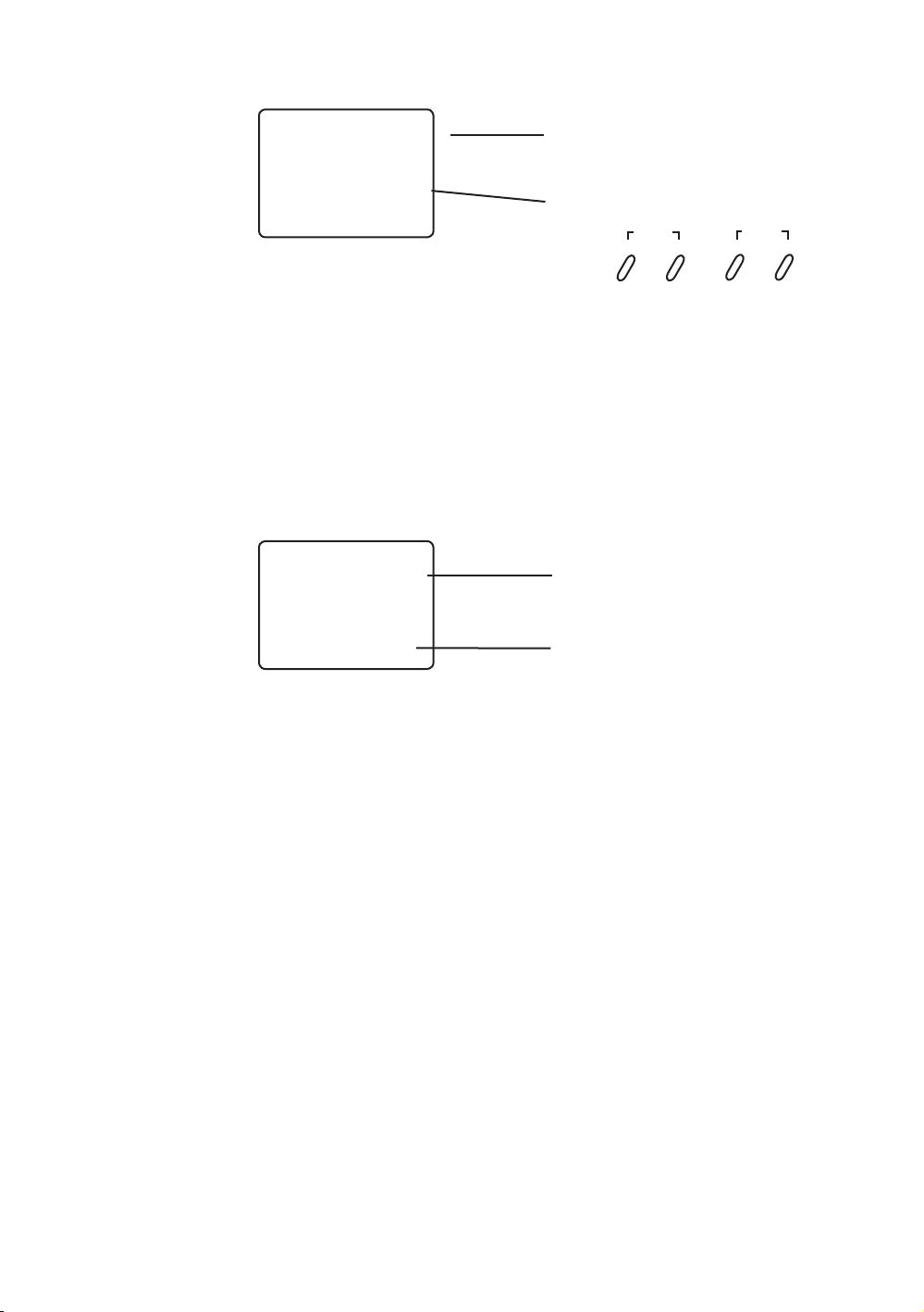
Servo Reversing
–
st
REV • NORM
–
1. With the transmitter power switch on, press the
SCROLL key to enter the Function mode.
2. Press the SCROLL key until “REV.NORM” appears on the screen.
The “ST” indicates the steering servo reversing screen.
3. Press the INCREASE or DECREASE key to move the cursor
to the desired servo direction (REV.NORM).
4. Press the CHANNEL key once to access the throttle servo reversing screen.
5. To select the direction of the throttle servo, repeat Step 3 above.
6. Repeat Steps 2 and 3 to adjust Auxiliary Channel 3 if needed.
Indicates Current Channel
ST = Steering
TH = Throttle
AUX = Auxiliary Channel 3 (optional)
Indicates Current Servo Direction
SCROLL
ENtER
ChaNNEL
INCREaSE
End-Point (Travel) Adjustment
Indicates Current Adjustment Position
ST = Steering
TH = Throttle
AUX = Auxiliary Channel 3 (optional)
E P A
–
st
CLEaR
DECREaSE
R/ B
I00
L/F = Left/Forward
R/B = Right/Brake
1. From the Servo Reverse function, press the SCROLL key once to access
the End-Point (Travel) Adjustment function (the EPA screen with “ST” will appear).
Indicates Current Value
Steering Adjustment
2. Rotate the steering wheel in the desired direction (left or right) to be adjusted.
3. Press the INCREASE or DECREASE keys to select the desired travel value.
Throttle Adjustment
4. Press the CHANNEL key once. TH will appear on the screen.
5. Pull the trigger for forward or push the trigger for brake adjustment.
6. Press the INCREASE or DECREASE keys to select the desired travel value.
Auxiliary Channel 3 Adjustment
If a third channel is not required, proceed to Step 9.
7. Press the CHANNEL key once. “AUX” will appear on the screen.
8. Press the INCREASE or DECREASE key to select the desired travel value.
9. Press the SCROLL and CHANNEL keys at the same time to exit the function mode.
4
Page 5
DX3.0 Quick
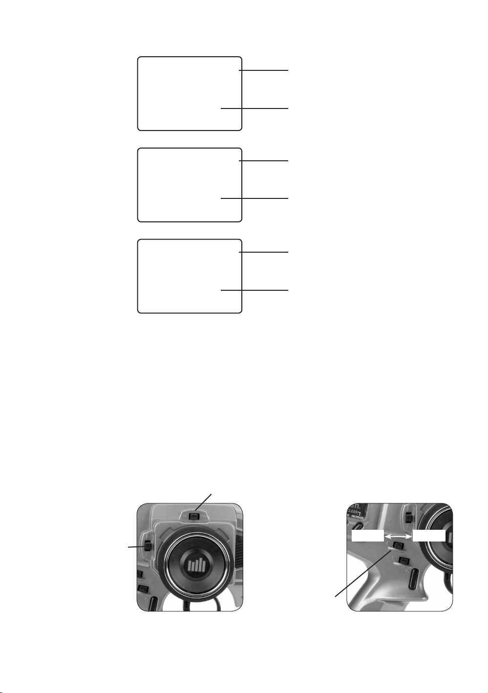
Servo Trim Adjustment
Start Setup
(continued)
Direct Trim
Access
TR IM
TR IM
–
STC
0
THC
Indicates Steering
Trim Function
Indicates Current Value
Indicates Throttle
Trim Function
Indicates Current Value
0
E P A
R/ B
Steering:
1. With the transmitter power switch on, move the digital steering trim lever in the desired
position to be adjusted. The steering trim value screen will appear automatically.
BRK
50
Brake Function
Indicates Current Value
Throttle Trim
Throttle:
2. With the transmitter power switch on, move the digital throttle trim lever in the desired
position to be adjusted. The throttle trim value screen will appear automatically.
Auxiliary Channel 3 Servo (If Activated):
3. With the transmitter power switch on, move the digital Grip Lever A in the desired
position to be adjusted. The Auxiliary Channel 3 value screen will appear automatically.
Steering Trim
Decrease
Grip Lever A
Channel 3
Increase
5
Page 6

43
"69
5)3
3Y
453
#"55&-
%4.(I[
463'"$&64&0/-:
ª)PSJ[PO)PCCZ*OD
DX3.0 with
Digital
Spectrum
Modulation
The DSM® system operates in the 2.4GHz band (that’s 2400MHz). This high frequency offers
a significant advantage. as it’s well out of the range of model-generated radio interference
(like motor and ESC noise). All the complex issues that now exist using 27 and 75MHz
radios with model-generated interfering noise are eliminated with this system. The DSM
system uses Direct Sequencing Spread Spectrum modulation to generate a wide signal on a
single frequency. The FCC requires that these systems be “smart”– incorporating collision
avoidance such that when a system is turned on, it scans the 2.4GHz band and selects a
channel that is not being used, then begins transmitting on that unused channel. 79 channels
are available and the odds of one DSS spread spectrum system interfering with another are
astronomically remote. The 2.4GHz spectrum has a capacity of 79 channels. In the unlikely
event that the spectrum is full, the 80th system will not connect or cause any interference
going into hold scan until a channel is free.
Binding
During the first installation, the receiver(s) must be bound to the transmitter. Binding is
necessary to program the receiver(s) to distinguish its corresponding transmitter from
others. Also fail-safe positions are transferred from the transmitter to the receiver during
binding.
It is necessary to bind the receiver to the transmitter during the first installation, and is
recommended when the receiver is moved from one vehicle to another. Receivers can be
re-bound to the same transmitter or to other transmitters an infinite number of times. Also
multiple receivers can be bound to a single transmitter, common when using one transmitter
to operate several models.
Only bound receivers and transmitters can connect. During power-up, the transmitter scans
for a free channel while the receiver scans for its bound transmitter. During the scanning
process, LEDs on both the transmitter and receiver flash rapidly. When control is achieved,
the LED remains on continuously.
In the unlikely event that the link is lost during use, the receiver will drive the servos to
their fail-safe positions that were preset during the binding process. If the receiver is turned
on prior to turning on the transmitter, the receiver will enter the fail-safe mode, driving the
servos to their preset fail-safe position. When the transmitter is turned on, normal control is
resumed.
To bind the receiver to the transmitter
1. Make sure the transmitter and receiver are turned off
6
Bind Button
LED
2. With the receiver off, press and hold the bind button on the receiver while turning on
the receiver.
3. Release the bind button when the LED flashes green.
Page 7
Binding
(continued)
4. With the transmitter off, place the transmitter steering wheel, throttle trigger and
auxiliary channels in their desired fail-safe positions (normally brake and straight-
ahead steering).
Bind Button
5. Press and hold the bind button on the transmitter while turning on
the transmitter.
6. Release the bind button after the green LED flashes.
After several seconds the LED on the receiver and the LED on the transmitter will quit
flashing and remain solid, indicating that the binding process was successful. Once binding
is complete, the system will automatically connect.
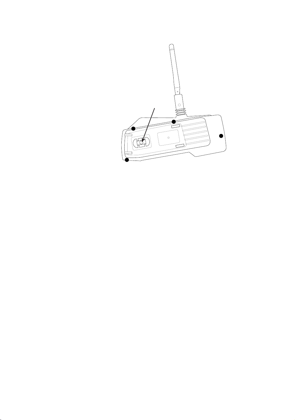
Antenna
At 8.5 inches in length, the receiver antenna is significantly shorter than conventional
antennas. The receiver has provisions that allow the antenna to exit the top of the receiver
or at the end of the receiver. To switch antenna positions, it is necessary to open the case
to change the antenna exit position. Like all antennas, it’s important to mount the antenna
vertically. In most cases the antenna can be mounted inside the body with no loss of range.
Mount the receiver antenna as recommended by the manufacturer of the vehicle, however, it
may be necessary to trim the plastic antenna tube (included with your vehicle) to allow the
antenna to extend at least 1/2” past the tip of the tube.
Note: If desired, the antenna can be shortened (cut) to exactly 3.6” with negligible loss of
range, and in some applications the short 3.6” length will make installation easier.
7
Page 8

System
Features
• DSM 2.4GHz Spread Spectrum Modulation
• Three channels
• Easy-to-read LCD graphics display
• Four-model memory
• Three-character model name entry
• Electronic digital trim levers for throttle and steering
• Two assignable electronic grip levers
• Third channel accessible through Grip Dial A
• Direct display trim function
• Sub-trim
• Steering rate adjustment
• Independent steering endpoint adjustments
• Brake/throttle endpoint adjustment
• Low battery alarm
• Charge jack receptacle (rechargeable batteries not included; order JRPB958)
R/C Safety
Precautions
For safe and reliable performance of your R/C model, please carefully read and follow these
guidelines:
1. Radio control models are not toys. They are capable of inflicting serious injury to
people and property. Use caution at all times when operating your model.
2. You are responsible for the safe operation of your R/C model. You must properly install,
test and operate your model with a clear sense of that responsibility. Do not take risks
that might endanger yourself or others.
3. Running an R/C car in the streets is very dangerous to both drivers and models. Avoid
running your model in areas occupied by full-size automobiles. To locate areas where
you can safely operate your model, you should contact your local hobby shop for R/C
tracks or clubs in your area.
4. When running an R/C boat, keep it away from any swimmers, full-size boats, or wildlife.
Also, watch carefully for fishing lines that can get tangled in the propeller.
5. If at any time while operating your RC model you observe abnormal model functioning,
end your operation immediately. Do not operate your model again until you are certain
the problem has been corrected.
CAUTION: Control of your model is impossible without sufficient voltage for the
transmitter and receiver. A weak transmitter battery will decrease your range of
operation and a weak receiver battery will slow servo movement and decrease
your range of operation. Check your receiver pack voltage often to avoid losing
control of your model.
Steering
Tension
Adjustment
8
Steering tension is adjustable via the recessed screw located beneath the steering wheel
(see page 9 for exact location). Turning the screw clockwise increases the steering tension.
Page 9
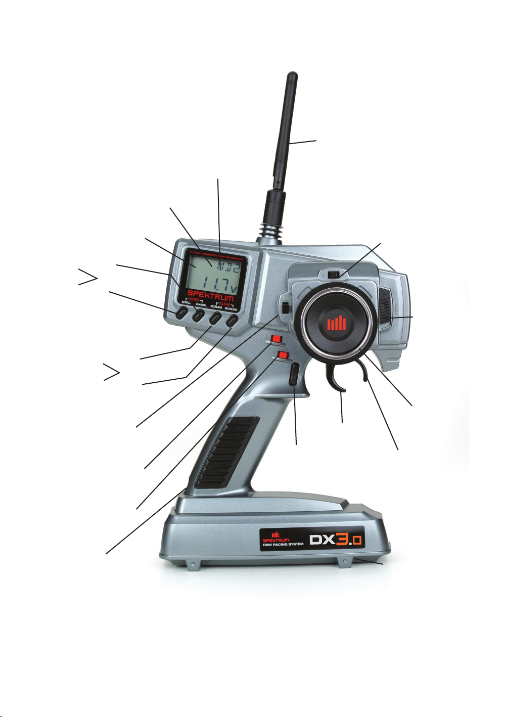
Control
Identification
and Location
Digital Voltage Reading
Channel Button
Enter Function
Mode Button
Antenna
Multidata LCD Display
Three Character
Name Input
Electronic Digital
Steering Trim Lever
Power Switch
Increase Button
Clear Function
Decrease Button
Electronic Digital
Throttle Trim Lever
Electronic Digital
Grip Lever A
(Access to Third Channel)
Electronic Digital
Grip Lever B
Charge Jack
* To remove the Battery Cover, press down on the ridges and push the cover in the direction
of the arrow. Remove the battery cover and install 8 “AA” batteries in the direction as molded
into the battery case. If the transmitter voltage fails to register, check for correct battery
installation and review voltage again.
Throttle Trigger
Grip Button C
Steering Wheel
Adjustable
Steering
Tension
Battery cover *
(8 “AA” Batteries Required
9
Page 10
n
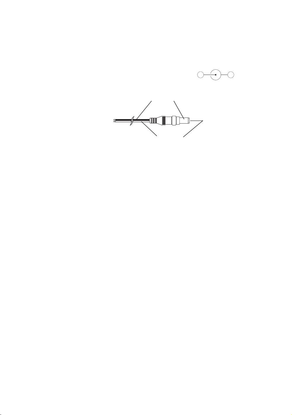
Charging Jack
Located on the left-hand side of the transmitter is the charging jack, which accepts only JR®
or Spektrum style wall chargers. Please do not attempt to use any other brand of wall charger
as it may be reverse polarity and can cause damage to your system. Only use the JR or
Spektrum type wall charger when the DX3.0 is equipped with Ni-Cd batteries.
Spektrum Transmitter Charge Jack Polarity:
Charger Pigtail For Transmitter
Black To Positive
Red To Negative
10
Page 11
7#BUUFSZ
5P3FTJTUPST
.FDIBOJDBM
4QFFE$POUSPM
#BUUFSZ#PY
'PSVTFXJUIPQUJPOBM
TFQBSBUFSFDFJWFSCBUUFSZQPXFS
3FDFJWFS
4XJUDI
#&$
$POOFDUPS
4FSWPT
43
"69
5)3
3Y
453
#"55&-
%4.(I[
463'"$&64&0/-:
ª)PSJ[PO)PCCZ*OD
7#BUUFSZ
5P.PUPS
&MFDUSPOJD
4QFFE$POUSPM
3FDFJWFS
4FSWP
43
"69
5)3
3Y
453
#"55&-
%4.(I[
463'"$&64&0/-:
ª)PSJ[PO)PCCZ*OD
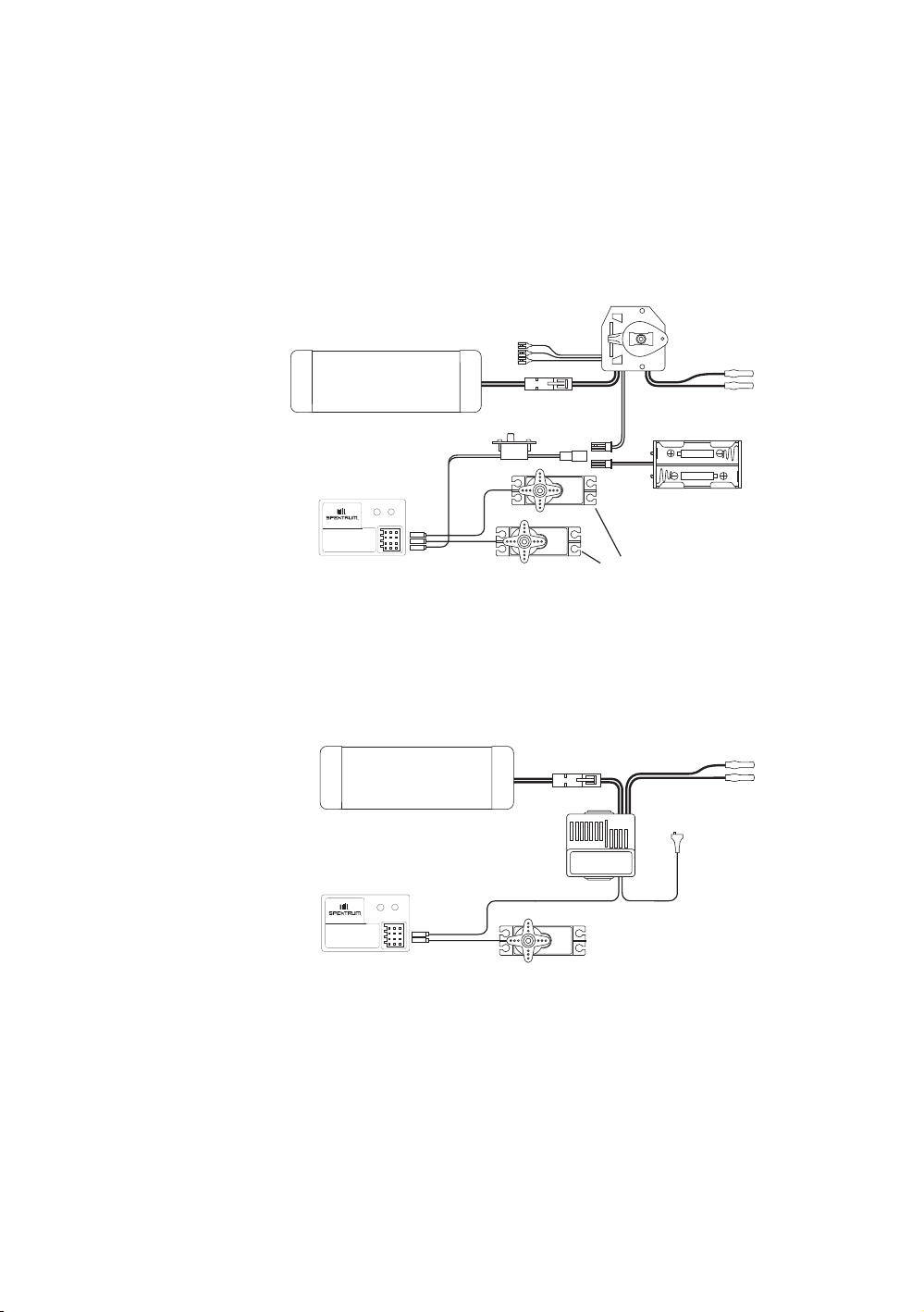
Receiver
Connections
and
Installation
Note: When using a separate Ni-Cd receiver battery as a power source, the operating
voltage range is 4.8–6.0V (4–5 cells) underload.
Attention: Make sure the male and female connectors have the correct polarity (+/–)
before connecting. Be sure to orient the servo plug correctly for proper insertion.
Most electronic speed controllers are set up for Battery Eliminator Circuit (B.E.C.) operation
and plug directly into your receiver. See Figure A for a typical setup and check your speed
controller’s manual for correct installation.
Figure A – Connections to B.E.C. and receiver with mechanical speed controller. Ni-Cd
battery and speed controller are not included in the radio set.
Figure B – Connections to B.E.C. and receiver with electronic speed controller. Ni-Cd
battery and speed controller are not included in the radio set.
11
Page 12
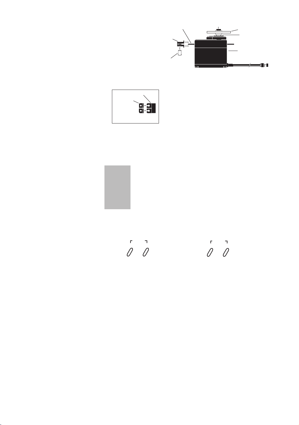
4FSWP-FBEX$POOFDUPS
4FSWP"SN3FUBJOJOH4DSFX
4FSWP"SN)PSO
4FSWP0VUQVU4IBGU
4FSWP&ZFMFU
3VCCFU(SPNNFUT
4FSWP.PVOUJOH'MBOHF
4FSWP$BTF
Servo Layout
3VCCFU(SPNNFUT
4FSWP.PVOUJOH'MBOHF
4OP6IEW
Note: Rubber
grommets (and
sometimes eyelets)
are used in fuelpowered vehicles.
Key Input and
Display
Key Use
SCROLL Used to move up through the available functions
CHANNEL Used to select the desired channel
INCREASE Used to increase the value of the selected function
DECREASE Used to decrease the value of the selected function
To enter the System Mode press the SCROLL andCHANNEL keys
simultaneously and hold while turning on the transmitter.
ENtER
SCROLL
ChaNNEL
To enter the Function Mode, press the
SCROLL key while the transmitter is on.
Press the INCREASE and DECREASE
keys simultaneously to clear the screen or
return to factory preset.
INCREaSE
CLEaR
DECREaSE
12
Page 13

Display
Normal Display Screen
Screens
When the power switch is turned on, the LCD screen will read as shown below. This screen
is referred to as the Normal Display.
Note: If any of the electronic trim buttons are moved while in this screen, the screen
will automatically change to display the trim in use. This is called the Direct Trim
Mode. For more information on the feature, please see page 7 of this manual.
-
-
MD1
10.2
Low Battery Screen/Lithium Battery Backup
When the voltage of the eight “AA” batteries drops below 9.0 volts, the DX3.0’s display
screen will alternate between the Normal (see above) and Low Battery screen (BAT),
and a continuous beeping will occur, indicating that the batteries need to be replaced
before further use.
v
bat
8.9
Lithium Battery
Your DX3.0 radio system is equipped with a five-year lithium battery backup system.
This system is designed to protect and retain all radio programming in the event that
the transmitter batteries drop below the required 9.0 volts, or the transmitter battery case
is removed during battery changes. If after five years it becomes necessary to replace the
lithium battery, return your system to the Horizon Service Center for repair
(see address, page 36).
Memory Backup Screen
If the Memory Backup screen appears, this indicates the possibility of a memory issue or
the lithium battery is dead. If you switch the power off and on again, and transmitter is in the
default mode with all data lost, it is suggested that the DX3.0 transmitter be returned to the
Horizon Service Center for servicing (see Warranty Information, page 36).
bak
v
–
–
ER
13
Page 14

Accessing the
System Mode
To enter the System Mode, press both the SCROLL and CHANNEL keys at the same time
while turning on the transmitter power switch. By pressing the SCROLL key, you can now
choose Model Select, Model Name Input, Auxiliary Channel 3, Grip Button C function, Data
Reset ot the Model Copy function as shown here on the System Mode flow chart. Information
for each function is located on the page number listed next to the function name on the flow
chart.
To exit the System Mode, press the SCROLL and CHANNEL keys at the same time, or
simply turn off the transmitter.
Note: If you turn the transmitter off and immediately enter System mode again, you
will be returned to the last System mode function used instead of the Model Select
function. While in System mode, there is no RF output generated by the transmitter.
adjustments can be performed with reduced battery power consumption. If you exit
System mode by pressing the SCROLL and CHANNEL key at the same time, RF
output will not be enabled until you first turn off the transmitter.
-
-
MDL
Model Select
(Page 15)
GBC
Grip Button C
Function
(Page 17)
I
-
-
MDI
Model Name
Entry
(Page 15)
I
AUX
Auxiliary
Channel 3
Function
(Page 16)
0
0
–
clr
I
CPY
2
Data Reset
(Page 19)
Copy Model
Data
(Page 19)
14
Page 15

Model Select
(System Mode)
The DX3.0 has memory for four models. This feature allows for four different models to
be operated with the same transmitter (additional receivers and servos must be purchased
separately) or one model with four different race setups.
-
-
MDL
Model Select Function
Model Name
Entry
(System Mode)
I
Model Number
Accessing the Model Select Function
1. Press the SCROLL and CHANNEL keys at the same time and hold.
2. Turn the transmitter power switch on to enter System Mode.
3. If “MDL” does not appear on the screen, press the SCROLL key until MDL appears.
4. Press the INCREASE or DECREASE keys to select the desired model number
(1, 2, 3, or 4).
5. Press the SCROLL key to access the Model Name Entry function.
6. To exit the System Mode, either turn the transmitter power switch off or press the
SCROLL and CHANNEL keys at the same time.
The DX3.0 allows a three-character name to be input for each of the four models available.
The current model, with name, will then be displayed in the Normal display screen. This
feature is useful to help identify different models, setups, etc. For information on selecting
models 1, 2, 3 or 4, please refer to the Model Select function above.
-
-
MDI
Flashing character indicates
the character to be adjusted
I
Current Model Number
Accessing the Model Name Entry Function
1. Press the SCROLL and CHANNEL keys at the same time and hold.
2. Turn on the transmitter power switch to enter the System Mode.
3. “MD1” should now be present on the screen.
4. Press the INCREASE or DECREASE keys to select the correct letter/number for the
first character (flashing).
5. To change the remaining two characters, press the CHANNEL key until the desired
character to be changed is flashing.
6. Press the SCROLL key to access the Auxiliary Channel 3 function.
7. To exit the System Mode, either turn the transmitter power switch off or press the
SCROLL and CHANNEL keys at the same time.
15
Page 16

Auxiliary
Channel 3
Function
The Auxiliary Channel 3 function of the DX3.0 allows you to select from 2 different types of
Channel 3 servo travel movements, or to inhibit the Auxiliary Channel 3 function. Use the
information below to select the correct Auxiliary Channel 3 function type for your particular
installation. It is suggested the O function (factory preset) be selected for most applications.
Select
(System Mode)
LN = The LN, or linear, servo travel function is designed to be used when an engine fuel
mixture servo is required. This function is most commonly used with gas-powered R/C
racing boats and is accessible through the Grip Dial A. In this function, the maximum travel
of the servo is determined by the End-Point Adjust function, page 23. The servo neutral
position can be altered proportionately via the Grip Dial A for fuel mixture adjustment. When
activated, fuel mixture trim values are visible for the Direct Trim function, page 27.
Auxiliary Channel 3
AUX
2P = The 2P, or 2 position, Servo Travel function is designed to be used as a transmission
gear shift channel. This feature is designed for use only with vehicles such as the Traxxas
T-Maxx. This function is accessible through the Grip Button C or Grip Dial A if Grip Button
C is occupied by another function. In this function, the servo’s travel can be selected to only
three positions: left, center and right. The left and right travel values are determined by the
End-Point Adjustment function, page 23.
AUX
Function
Linear Movement
(fuel mixture servo)
®
Auxiliary Channel 3
Function
16
Non-linear Two-Position Movement
2P
0 = The 0 or Inhibit function allows the Brake End-Point Adjustment function, page 31, to be
used. This function is designed to be used with most types of electric and gas-powered RC
cars. This feature is extremely popular, as it allows the amount of panic braking accessible
through the throttle trigger’s braking position to be adjusted during operation for maximum
effectiveness. When activated, the braking valves will be visible via the Direct Trim function,
page 27.
AUX
0
(Traxxas shiftable transmission use)
Auxiliary Channel 3
Function
Channel 3 is inhibited
(Grip Dial A braking function is now activated)
Page 17

Auxiliary
Channel 3
Function
Select
(System Mode)
continued
Accessing the Auxiliary Channel 3 Function
LN = Linear servo movement
2P = 2-position servo movement
0 = Inhibited (Grip Dial A Braking is now activated)
1. Press the SCROLL and CHANNEL keys at the same time and hold.
2. Turn on the transmitter power switch to enter the System Mode.
3. Press the SCROLL key until “AUX” appears on the screen.
4. Press the INCREASE or DECREASE key to select the correct Auxiliary Channel 3
function type to be used.
5. Press the SCROLL key to access the Grip Button C Select function.
6. To exit the System mode, either turn the transmitter power switch off or press the
SCROLL and CHANNEL keys at the same time.
Grip Button C
Function
Select
(System Mode)
The Grip Button C function of the DX3.0 allows you to select from 3 different functions
available. Use the information below to select the correct Grip Button C assignment for your
particular installation.
Grip Button C
GBC
A
“0”: Off. (Default) If “AUX” is “2P”, then “2P” replaces “0” in this screen.
“Eb”: ESB (Emergency Steering Button). To cancel the “STG” regulation
for panic steering.
“LA”: Lap Timer.
Note: If “LA” or “Eb” is selected and “2P” is assigned to the Auxiliary
Channel 3 function, the Auxiliary Channel 3 function is moved to Grip Dial A (factory preset).
2P = The 0 or off function, is the default setting and does not assign a function to Grip
Button C. If the Auxiliary Channel 3 function is set to “2P” or 2-position, “2P” will appear in
this screen in place of “0” and Grip Button C will function as the gear select button.
Function
Lap Timer
GBC
0
Grip Button C
Function
Grip Button C is inhibited
17
Page 18

Grip Button C
Function
Select
(System Mode)
continued
E6 = The Eb orEmergency Steering Button function is designed to override the value of Grip
Dial B and provide 100% steering rate. This feaure is useful if you have reduced the steering
rate to make your vehicle easier to drive but need full steering in an emergency situation such
as a collision.
Grip Button C
GBC
E6
LA = The LA or Lap Timer function is designed to be used when you want to enable the
recording of individual lap time. The Lap Timer function is described on page 25..
GBC
LA
Function
Emergency Steering Button
is activated
Grip Button C
Function
Lap Timer Button
is activated
1. Press the SCROLL and CHANNEL keys at the same time and hold.
2. Turn on the transmitter power switch to enter the System Mode.
3. Press the SCROLL key until “GBC” appears on the screen.
4. Press the INCREASE or DECREASE key to select the correct Grip Button C function
type to be used.
5. Press the SCROLL key to access the Data Reset function.
6. To exit the System mode, either turn the transmitter power switch off or press the
SCROLL and CHANNEL keys at the same time.
18
Page 19

Data Reset
(System Mode)
The Data Reset function allows you to reset all the programming in the selected model
(1, 2, 3 or 4) to the factory default settings and to copy model data from one model memory
to another. Before using the Data Reset function, it’s important to enter the Model Select
function and check to make sure the current model number indicated (1, 2, 3 or 4) is the
model to which you want to reset to the factory default settings. The Model Select function is
described on page 15.
CLR
Copy Model
Data
(System Mode)
I
Model to be Reset
Accessing the Data Reset Function
1. Press the SCROLL and CHANNEL keys at the same time and hold.
2. Turn on the transmitter power switch to enter the System Mode.
3. Press the SCROLL key until “CLR” appears on the screen.
4. Press the INCREASE or DECREASE keys at the same time to reset the data. To
confirm that the selected model’s programming has been reset, a beep will sound and
the model number selected (1, 2, 3 or 4) will stop flashing.
5. Press the SCROLL key to access the Copy Model Data function.
6. To exit the System mode, either turn the transmitter power switch off or press the
SCROLL and CHANNEL keys at the same time.
CPY
Model being copied to
2
Accessing the Copy Model Data Function
1. Press the SCROLL and CHANNEL keys at the same time and hold.
2. Turn on the transmitter power switch to enter the System Mode.
3. Press the SCROLL key until “CPY” appears on the screen.
4. Press the INCREASE or DECREASE key to select the desired model number you want
the current model data copied to. The selected model number should be flashing.
5. Press the INCREASE and DECREASE keys at the same time to copy the current model
data into the selected model number. To confirm that the selected model has been
copied to, a beep will sound and the model number selected (1, 2, 3 or 4) will stop
flashing.
6. To exit the System mode, either turn the transmitter power switch off or press the
SCROLL and CHANNEL keys at the same time.
19
Page 20

Accessing
the Function
Mode
The Travel Adjust feature of the DX3.0 allows the maximum travel of both the steering,
throttle and Channel 3 (optional) servos to be increased or decreased in each direction to
achieve the exact servo movement needed. The adjustment range is from 0 % to 125%.
The travel adjustment is factory set to 100% for both channels. The travel adjustment value
displayed on the screen depends on the current position of the steering wheel, trigger, or trim
lever to be adjusted. This feature is very useful either to maximize servo travel or to reduce
servo over-travel to eliminate servo binding (servo moves further than control mechanism
allows), without the need for mechanical linkage adjustment.
Mode Key
R/B
E X P
E P A
L/F
M I X
TDB
0
–
ST
–
ST
I00
–
STL
0
Throttle
Deadband
(page 21)
Channel
Key
Channel
Key
Channel
Key
Channel Key
E X P
E P A
R/B
I00
M I X
THF
TH
THB
0
Exponential
(page 22)
Channel
Key
Mixing
(page 24)
E P A
L/F
I00
AUX
End-Point
Adjustment
(page 23)
20
L A P
TR IM
40
20
–
STS
0
–
ST
REV • NORM
–
–
Lap Timer
(page 25)
Channel
Key
Channel
Key
TR IM
SB • TR M
–
THS
0
TH
REV • NORM
–
Channel
Key
Channel
Key
TR IM
SB • TR M
–
AUS
0
AUX
REV • NORM
–
Sub-Trim
(page 26)
Servo
Reversing
(page 26)
Page 21

Throttle
Deadband
(Function Mode)
The throttle deadband feature is used to reduce/eliminate the dead throttle area that exists at
neutral to the starting point of throttle and from neutral to the starting point of braking. This
area is sometime known as deadband. As more throttle trim (also known as static brake)
is applied, more of the dead trigger area right off neutral exists. To eliminate the throttle
deadband, adjust a forward value such that your vehicle’s wheels just start to turn when the
trigger is slightly squeezed. This provides the most accurate feel and eliminates the dead
area in the throttle. To eliminate the braking deadband, adjust the brake value such that
your vehicle starts to slow down when the trigger is slightly pushed. This provides the most
accurate brake feel and eliminates the dead area when braking.
Forward Adjustment
(depends on trigger position)
Current Value
Brake Adjustment
(depends on trigger position)
Current Value
L/ F
TDB
0
TDB
R/ B
0
Value: 0% to 100%
Clear = 0%
Accessing the Throttle Deadband Function
1. Turn the transmitter power switch on.
2. Press the SCROLL key to access Function mode.
3. Press the SCROLL key until “TDB” appears on the screen.
4. Move the trigger accordingly to adjust the forward or braking deadband.
5. Press the INCREASE or DECREASE key to select the desired value necessary to
eliminate dead area.
6. Press the SCROLL key to access Exponential mode.
7. To exit the Function mode, either turn the transmitter power switch off or press the
SCROLL and CHANNEL keys at the same time.
21
Page 22

Exponential
(Function Mode)
The Exponential feature of the DX3.0 allows you to alter the response rate of the steering or
throttle control around neutral without affecting the maximum amount of steering or throttle
available. The adjustment range is from -100% to 0% (Linear) to +100%. Exponential is
factory set to linear for both steering and throttle. Exponential is often used to settle down a
car that is twitchy around center without giving up maximum steering response. The DX3.0
provides both positive (increase sensitivity at neutral) and negative (decrease sensitivity at
neutral) exponential values.
Steering Exponential
Adjustment
Current Value
E X P
–
ST
Forward Throttle Exponential
E X P
THF
Adjustment
Current Value
Braking Exponential
E X P
THB
Adjustment
Current Value
Values: -100% to Linear (LN) to +100%
Accessing the Exponential Function
1. Turn the transmitter power switch on.
2. Press the SCROLL key to access Function mode.
3. Press the SCROLL key until “EXP” appears on the screen.
4. Press the INCREASE or DECREASE key to select the desired value necessary
exponential value.
5. Press the SCROLL key to access the travel End-Point Adjustment function.
6. To exit the Function mode, either turn the transmitter power switch off or press the
SCROLL and CHANNEL keys at the same time.
22
Page 23

End-Point
Adjustment
(Function Mode)
The End-Point Adjustment feature of the DX3.0 allows the maximum travel of both the
steering, throttle and Auxiliary Channel 3 (optional) servos to be increased or decreased
in each direction to achieve the exact servo movement needed. The End-Point Adjustment
range is from 0% to 125% and is factory set to 100% for both channels. The value displayed
on the screen depends on the current position of the steering wheel, trigger, or trim lever to
be adjusted. This feature is very useful either to maximize servo travel or to reduce servo
over-travel to eliminate servo binding (servo moves further than control mechanism allows),
without the need for mechanical linkage adjustment.
The screens below are accessed by turning the wheel to the desired direction to be adjusted
(left or right), by moving the trigger to the forward or backward (brake) position, or by
moving the Grip Lever A to the forward or back positions.
L/F
R/B
E P A
I00
E P A
I00
–
ST
ST
Steering Left
End-Point Adjustment
Current Value
Values: 0 to 125
Clear = 100
Steering Right
End-Point Adjustment
Current Value
Values: 0 to 125
Clear = 100
E P A
L/F
E P A
R/B
TH
I00
TH
I00
Forward Throttle
End-Point Adjustment
Current Value
Values: 0 to 125
Clear = 100
Backward Throttle (Brake)
End-Point Adjustment
Current Value
Values: 0 to 125
Clear = 100
Channel 3 Screens (optional)
Left/Right Travel
Adjustment (function LN)
AUX
E P A
L/F
I00
Functions & 2P Functions 2P only
or Forward Travel Adj.
(function 2P) accessible
through Grip Button C
Current Value
Values: 0 to 90
Clear = 100
E P A
R/B
I00
AUX
Rearward Travel
Adjustment
(function 2P)
accessible through
Grip Button C
Current Value
Values: 0 to 90
Clear = 100
Accessing the End-Point Adjustment Function
1. Turn the transmitter power switch on.
2. Press the SCROLL key to access Function mode.
3. Press the SCROLL key until “EPA” appears on the left side of the screen.
4. Press the CHANNEL key to select the desired channel to be adjusted.
5. Move the steering wheel, trigger or Grip Button C in the desired direction for adjustment
(left/right, forward/reverse or brake). Press the INCREASE or DECREASE key to
achieve the desired amount of travel. Move the wheel, trigger or Grip Button C in the
opposite direction to adjust the travel in the opposite direction.
Note: For Auxiliary Channel 3 function, if LN is selected, only L/F is adjustable. And if
Emergency Steering Button is Eb or LA, Auxiliary Channel 3 defaults to Grip Lever A.
6. Press the SCROLL key to access the Mixing Adjustment function.
7. To exit the Function mode, either turn the transmitter power switch off or press the
SCROLL and CHANNEL keys at the same time.
Note: When setting the End-Point Adjustment values for the Steering function, it is
suggested that, if possible, the maximum travel values be set to an equal value in both
directions to maintain proper steering control.
23
Page 24

Programmable
Mixing
(Function Mode)
The DX3.0 offers two different mixing adjustments that allow for mixing one channel to another
channel. The mixes available are Steering-to-Auxiliary Channel Mixing and Throttle-to-Auxiliary
Channel Mixing. Each direction is independently adjustable. Popular use of this function
includes 4-wheel steering and independent front and rear wheel brakes.
For example, Throttle-to-Auxiliary channel mixing can be used for independent front and rear
wheel brakes. Each time the throttle/brakes is moved, the auxiliary channel will move in the
direction and to the value input being given by the throttle channel. Mixing is proportional, so
small inputs to the throttle will result in small output from the auxiliary
channel. The adjustment range is from -125% to 0% to 125%. If the rate is negative, the
channel is mixed in the opposite direction.
Both mixes share a single mixing “offset.” The purpose of the mixing offset is to redefine the
neutral position of the auxiliary channel, which can be set using Grip Lever A when
“LN” is selected in the Auxiliary Channel 3 function. If the “LN” selection is turned off in the
Auxiliary Channel 3 function with an offset value currently present, the value will
continue to act as a mixing offset until the value is either cleared or changed. If a mix is not
required, it is strongly suggested the mixing rate be set for 0%, which is the default.
–
M I X
STL
I0
M I X
THB
–
I0
Accessing the Mixing Adjustment Function
1. Turn the transmitter power switch on.
2. Press the SCROLL key to access Function mode.
3. Press the SCROLL key until “MIX” appears in the screen.
4. Press the CHANNEL key to select the desired mix to be used.
5. Move the steering wheel or trigger in the desired direction for adjustment (left/right,
forward/reverse or brake). Press the INCREASE or DECREASE key to achieve the
desired amount of mixing. Move the wheel or trigger in the opposite direction to adjust
the mixing in the opposite direction.
Note: For Auxiliary Channel 3 function, if LN is selected, only L/F is adjustable.
6. Press the SCROLL key to access the Lap Timer (if enabled) or Sub-Trim function.
7. To exit the Function mode, either turn the transmitter power switch off or press the
SCROLL and CHANNEL keys at the same time.
24
Page 25

Lap Timer
(Function Mode)
The Lap Timer function of the DX3.0 allows the recording of individual lap times based on a
999 second up-timer. Up to 50 laps and times from 3.0 to 99.9 seconds can be stored in
memory for review at a later time. The Lap Timer function will only be enabled and shown in
Function mode if Grip Button C (System Mode) is set to “LA.” With the Lap Timer enabled,
pressing the channel key will alternate between the Normal display screen and Up-Timer
display screen.
The Lap Timer is started by pressing Grip Button C. Once active, as shown by the blinking word
“LAP,” pressing Grip Button C again will begin recording the time of the next lap.
Note: A 3.0 second lap is the quickest lap allowed. This prevents accidental double pushing of
Grip Button C when recording lap times. If more than 50 laps are recorded, each new lap will
overwrite the oldest lap held in memory.)
To stop the Lap Timer, press the Increase and Decrease keys at the same time. To restart the Lap
Timer, press Grip Button C. To reset the Up-Timer, press the Channel key to show the Up-Timer
display screen. With the Up-Timer stopped, press the Increase and Decrease keys at the same
time to reset.
To review or reset lap times you must be in the Lap Timer function mode screen. Upon entering
this function, the screen will always show the last lap time recorded. Use the
Increase or Decrease keys to view the desired lap(s).
Note: If a recorded lap time is greater than 99.9 seconds, “OVR” will be displayed.
To clear all lap times, press the Increase and Decrease keys at the same time.
Recorded Lap Time to 1/10th of a second
(i.e. 40.1 sec.)
Current Lap Number
–
L A P
40I
20
Accessing the Lap Timer Function
1. Turn the transmitter power switch on.
2. Press the SCROLL key to access Function mode.
3. Press the SCROLL key until “LAP” appears in the screen.
4. Press the INCREASE or DECREASE keys to view the desired lap time(s).
5. To reset all lap times, press the INCREASE or DECREASE keys at the same time.
6. Press the SCROLL key to access the Sub-Trim function.
7. To exit the Function mode, either turn the transmitter power switch off or press the
SCROLL and CHANNEL keys at the same time.
25
Page 26

Sub-Trim
(Function Mode)
The Sub-Trim function of the DX3.0 is an electronic trimming feature that allows the neutral
position of the servo on either the steering, throttle or auxiliary channel (optional) to be moved,
while allowing the electronic trim lever for that channel to remain in the center position. This
feature is very useful as it allows the servo arm/wheel position to be moved to help with control
linkage installation, eliminating the need to make mechanical linkage adjustments.
Although the Sub-Trim function is a very useful feature, it is suggested that only small amounts
of sub-trim be used so that no unwanted, non-equal servo travel is created. It is suggested that
less than 30 points of Sub-Trim be used during adjustment. If more than 30 points of Sub-Trim
are required, it is suggested that a mechanical linkage adjustment be performed.
Servo
Reversing
(Function Mode)
–
TR IM
–
STS
0
Values: R/B 125 0 R/F 125
Current Channel
STS = Steering
THS = Throttle
AUS = Auxiliary Channel 3
Current Value
Accessing the Sub-Trim Function
1. Turn the transmitter power switch on.
2. Press the SCROLL key to access Function mode.
3. Press the SCROLL key until “TRIM” appears in the screen.
4. Press the CHANNEL key to select the desired channel to be adjusted (Steering, Throttle
or Auxiliary Channel 3).
5. Press the INCREASE or DECREASE keys until the proper servo position is achieved.
6. Press the SCROLL key to access the Servo Reversing function.
7. To exit the Function mode, either turn the transmitter power switch off or press the
SCROLL and CHANNEL keys at the same time.
The Servo Reversing feature of the DX3.0 is a very convenient feature when setting up a new
model. The purpose of the servo reversing function is to change the direction of the
servo rotation in relation to the wheel/trigger movement. The Servo Reversing function is
available for the steering, throttle and Auxiliary Channel 3.
26
–
ST
REV • NORM
–
Current Channel
STS = Steering
THS = Throttle
AUS = Auxiliary Channel 3
Current Servo Direction
Accessing the Servo Reversing Function
1. Turn the transmitter power switch on.
2. Press the SCROLL key to access Function mode.
3. Press the SCROLL key until “REV•NORM” appears in the screen.
4. Press the CHANNEL key to select the desired channel to be changed (Steering, Throttle
or Auxiliary Channel 3).
5. Press the INCREASE or DECREASE keys to move the cursor to the desired direction
of travel.
6. To exit the Function mode, either turn the transmitter power switch off or press the
SCROLL and CHANNEL keys at the same time.
Page 27

Accessing the
Direct Trim
Mode
The Direct Trim Mode function of the DX3.0 is accessible through the use of the electronic
throttle or steering trim levers, as well as the two electronic grip levers (A&B) located on
the upper portion of the grip handle. This function allows for quick trim adjustment of these
controls.
–
–
Steering Trim
TR IM
STS
(page 28)
0
Throttle Trim
TR IM
THC
(page 29)
0
RA TE
–
STG
Steering Dual-Rate
(Grip Lever B)
(page 30)
70
To access the Direct Trim Mode function, turn the transmitter power switch on. Next, move
the desired trim lever to be adjusted. The appropriate screen for the selected trim lever will
be displayed. To adjust, simply move the trim lever in the desired direction until the correct
amount of trim is achieved. Once the desired trim is achieved, the screen will return to the
Normal display screen after approximately two seconds from the last trim input. If the Increase or Decrease keys are pressed any time during the two seconds, the system will return
to the previous screen in use.
Only present when Auxiliary function “0” is selected
Brake Travel Adjustment
(Grip Lever A), (page 31)
Only visible when the Auxiliary Channel
3 function “0” has been selected. Refer to
Auxiliary Channel 3 function, page 16,
for clarification.
Auxiliary Channel 3 Trim Adjustment (LN
mode only). Refer to Auxiliary Channel 3
function, page 32, for clarification.
*
E P A
R/B
BRK
50
AUX
0
*
*Note: When Auxiliary Channel 3 function 2P is selected, the two screens above are not
present.
27
Page 28

Steering Trim
(STC)
The DX3.0 electronic Steering Trim lever, located just above the steering wheel, allows the
center position of the servo to be manipulated in either direction to achieve precise centering
of the steering assembly. Steering Travel End-Point Adjustment values (page 23) remain
completely independent from the steering trim, unless the trim value exceeds the selected
end-point values. (For example: If trim value is set at 30 and end-point values at 15, steering
trim will override/alter the end-point value.)
–
TR IM
stC
0
Values: L/F 30 0 R/B 30
Each click will provide 0.3° of trim to the center of the steering servo with a maximum of 12° allowed.
Note: Each click will not always result in a change of the value displayed.
To adjust the steering trim servo position, move the electronic Steering Trim lever either to
the left (+) or the right (-). As soon as the trim is moved, the “STC” Steering Trim screen will
appear and will continue to be displayed unless the trim lever is untouched for a period of
two seconds. To reset the trim value to 0, press the INCREASE and DECREASE keys at the
same time while the “STC” screen is displayed.
Steering Trim Screen
Indicates current value
Steering Trim
28
Steering Trim Location
Page 29

Throttle Trim
(THC)
The DX3.0’s electronic Throttle Trim lever, located to the left of the steering wheel, allows the
center position of the servo to be manipulated in either direction to achieve precise centering
of the throttle trigger neutral position. Throttle End-Point adjustment values (page 23) remain
completely independent from the throttle trim, unless the trim value exceeds the selected
end-point values. (For example: If the trim value is set at 40 and the end-point values at 30,
Throttle Trim will override/alter the end-point value.)
TR IM
Values: L/F 60 0 R/B 60
Each click will provide 0.3° of trim to the throttle servo with a maximum of 24° allowed.
Note: Each click will not always result in a change of the value displayed.
To adjust the Throttle Trim servo position, move the electronic steering trim lever either up
(+) or down (-). As soon as the trim is moved, the “THC” Throttle Trim screen will appear and
will continue to be displayed unless the trim lever is untouched for a period of two seconds.
To reset the trim value to zero, press the INCREASE and DECREASE keys at the same time
while the “THC” screen is displayed.
Throttle Trim
Increase
Decrease
THC
0
Current value
Throttle Trim Location
29
Page 30

Grip Lever B:
Steering Dual
Rate Trim
Adjustment
STG
The Steering Dual Rate Trim Adjustment, located at Grip Lever B, allows the dual rate value
(maximum servo travel) to be increased or decreased within a range from 100% through
20% of the total end-point value established in the steering EPA function. This function
is very useful in race conditions as it allows you to custom tailor the steering radius and
sensitivity for the current track conditions. Please note that since the Dual Rate value shown
in the “STG” screen is the percentage of the end-point value established in the steering EPA
function, the value will not always increase or decrease each time the Grip Lever B is moved.
–
RA TE
stG
%
70
If the Emergency Steering button function (page 17) is active, pressing Grip Button C will
restore the steering dual rate to 100% until the button is released.
To adjust the Steering Dual Rate value, move the electronic Grip Lever B either left (-) or
right (+). As soon as the trim is moved, the “STG” Steering Dual Rate screen will appear
and will continue to be displayed unless the Grip Lever B is untouched for a period of two
seconds. To reset the trim value to the factory preset setting of 70%, press the INCREASE
and DECREASE keys at the same time while the “STG” screen is displayed.
Grip Lever B
Steering
Dual-Rate Trim
Current Value
(20% to 100%)
Decrease
Increase
30
Page 31

Grip Lever A:
BrakeEnd-Point
Adjustment
BRK/Auxiliary
Channel 3
Access
The Brake End-Point Adjustment, located at Grip Lever A, allows the maximum servo travel
on the braking side of the throttle trigger to be increased or decreased from 100% to 0%
(off). This function is very useful in race conditions as it allows the racer to custom tailor
the “panic” brake value to maximize the car’s braking power for the current track conditions.
Please note that since the brake end-point value shown in the “BRK” screen is a percentage
of the total braking value established in the End-Point Adjustment function (page 23), the
value will not always increase or decrease each time the Grip Lever A is moved.
Note: If Grip Lever A is assigned an Auxiliary Channel 3 function by selecting “LN” or “2P”
with Grip Button C in use, the Brake End-Point Adjustment will not be available.
To adjust the brake end-point value, move the electronic Grip Lever A either left (–) or right (+).
As soon as the grip lever is moved, the BRK End-Point Adjustment screen will appear and will
continue to be displayed unless the Grip Lever A is untouched for a period of two seconds.
R/ B
E P A
Grip Lever A
Brake Trim
BRK
50
Current Value
(100 to 0%)
Decrease Increase
Move the grip lever A to the left or right to
decrease or increase values.
31
Page 32

Auxiliary
Channel 3
When selected, Grip Lever A can be used to access the Auxiliary Channel 3 function of the
DX3.0 for use as a fuel mixture channel.
Access
(Fuel Mixture)
Auxiliary
Channel 3
(Transmission
Shift Selector)
AUX
0
Current value
When the LN (linear) Auxiliary Channel 3 function is selected, Grip Lever A can be used to
change the neutral position of the servo to lean or richen the engine’s fuel mixture. Once the
desired fuel mixture has been achieved, the Grip Lever A value indicated on this screen can
be transferred manually to the Sub-Trim function (page 26) and the value of the AUX screen
can be returned to zero. Please refer to the diagram below for proper grip lever operation.
When the 2P Auxiliary Channel function is selected, the Grip Lever A can be used to move
the Auxiliary 3 Channel servo to one of two positions (left/right or forward/reverse) when LA
or Eb is selected for the Grip Button C function. Please refer to diagram A below for proper
shifting procedures.
Note: The End-Point Adjustment function (page 23) is used to set the forward and reverse
gear servo travel positions.
(Transmission Use)
(Fuel Mixture Use)
Forward Gear Reverse Gear
Decrease
Increase
32
Grip Lever A
Brake Trim
Page 33

DX3.0 Data
MODEL NUMBER
MODEL NAME
GRIP BUTTON C
THROTTLE DEADBAND
EXPONENTIAL
END-POINT ADJ.
MIXING
SUB-TRIM
SERVO REVERSING
1 2 3 4
LA/Eb/
0
STEERING THROTTLE AUXILIARY
%
REV•NORM
REV•NORM REV•NORM
SYSTEM MODE
FUNCTION MODE
DIRECT MODE
LN/2P/
0
% %
F B
% %
F B
F B
% %
F B
L R L R
% %
L R
TRIM VALUES
GRIP LEVER B
STEERING D/R
GRIP LEVER A
VALUES
STEERING
-/+
THROTTLE
-/+
AUX CHANNEL 3
-/+
BRAKE EPA AUX FUNCTION “LN”
%
%
AUX FUNCTION
Sheet
33
Page 34

DX3.0 Data
MODEL NUMBER
MODEL NAME
GRIP BUTTON C
THROTTLE DEADBAND
EXPONENTIAL
END-POINT ADJ.
MIXING
SUB-TRIM
SERVO REVERSING
1 2 3 4
LA/Eb/
0
STEERING THROTTLE AUXILIARY
%
REV•NORM
REV•NORM REV•NORM
SYSTEM MODE
FUNCTION MODE
DIRECT MODE
LN/2P/
0
% %
F B
% %
F B
F B
% %
F B
L R L R
% %
L R
TRIM VALUES
GRIP LEVER B
STEERING D/R
GRIP LEVER A
VALUES
STEERING
-/+
THROTTLE
-/+
AUX CHANNEL 3
-/+
BRAKE EPA AUX FUNCTION “LN”
%
%
AUX FUNCTION
Sheet
34
Page 35

DX3.0 Data
MODEL NUMBER
MODEL NAME
GRIP BUTTON C
THROTTLE DEADBAND
EXPONENTIAL
END-POINT ADJ.
MIXING
SUB-TRIM
SERVO REVERSING
1 2 3 4
LA/Eb/
0
STEERING THROTTLE AUXILIARY
%
REV•NORM
REV•NORM REV•NORM
SYSTEM MODE
FUNCTION MODE
DIRECT MODE
LN/2P/
0
% %
F B
% %
F B
F B
% %
F B
L R L R
% %
L R
TRIM VALUES
GRIP LEVER B
STEERING D/R
GRIP LEVER A
VALUES
STEERING
-/+
THROTTLE
-/+
AUX CHANNEL 3
-/+
BRAKE EPA AUX FUNCTION “LN”
%
%
AUX FUNCTION
Sheet
35
Page 36

DX3.0 Data
MODEL NUMBER
MODEL NAME
GRIP BUTTON C
THROTTLE DEADBAND
EXPONENTIAL
END-POINT ADJ.
MIXING
SUB-TRIM
SERVO REVERSING
1 2 3 4
LA/Eb/
0
STEERING THROTTLE AUXILIARY
%
REV•NORM
REV•NORM REV•NORM
SYSTEM MODE
FUNCTION MODE
DIRECT MODE
LN/2P/
0
% %
F B
% %
F B
F B
% %
F B
L R L R
% %
L R
TRIM VALUES
GRIP LEVER B
STEERING D/R
GRIP LEVER A
VALUES
STEERING
-/+
THROTTLE
-/+
AUX CHANNEL 3
-/+
BRAKE EPA AUX FUNCTION “LN”
%
%
AUX FUNCTION
Sheet
36
Page 37

DX3.0 Data
MODEL NUMBER
MODEL NAME
GRIP BUTTON C
THROTTLE DEADBAND
EXPONENTIAL
END-POINT ADJ.
MIXING
SUB-TRIM
SERVO REVERSING
1 2 3 4
LA/Eb/
0
STEERING THROTTLE AUXILIARY
%
REV•NORM
REV•NORM REV•NORM
SYSTEM MODE
FUNCTION MODE
DIRECT MODE
LN/2P/
0
% %
F B
% %
F B
F B
% %
F B
L R L R
% %
L R
TRIM VALUES
GRIP LEVER B
STEERING D/R
GRIP LEVER A
VALUES
STEERING
-/+
THROTTLE
-/+
AUX CHANNEL 3
-/+
BRAKE EPA AUX FUNCTION “LN”
%
%
AUX FUNCTION
Sheet
37
Page 38

Warranty
and Service
Information
Spektrum® 1-Year Limited Warranty Period
Horizon Hobby, Inc. guarantees this product to be free from defects in both material and workmanship for a period of 1
year from the date of purchase.
Limited Warranty & Limits of Liability
Pursuant to this Limited Warranty, Horizon Hobby, Inc. will, at its option, (i) repair or (ii) replace, any product determined
by Horizon Hobby, Inc. to be defective. In the event of a defect, these are your exclusive remedies.
This warranty does not cover cosmetic damage or damage due to acts of God, accident, misuse, abuse, negligence,
commercial use, or modification of or to any part of the product. This warranty does not cover damage due to improper
installation, operation, maintenance, or attempted repair by anyone other than an authorized Horizon Hobby, Inc. service
center. This warranty is limited to the original purchaser and is not transferable. In no case shall Horizon Hobby’s
liability exceed the original cost of the purchased product and will not cover consequential, incidental or collateral
damage. Horizon Hobby, Inc. reserves the right to inspect any and all equipment involved in a warranty claim. Repair
or replacement decisions are at the sole discretion of Horizon Hobby, Inc. Further, Horizon Hobby reserves the right to
change or modify this warranty without notice. REPAIR OR REPLACEMENT AS PROVIDED UNDER THIS WARRANTY IS
THE EXCLUSIVE REMEDY OF THE CONSUMER. HORIZON HOBBY, INC. SHALL NOT BE LIABLE FOR ANY INCIDENTAL
OR CONSEQUENTIAL DAMAGES. As Horizon Hobby, Inc. has no control over use, setup, final assembly, modification
or misuse, no liability shall be assumed nor accepted for any resulting damage or injury. By the act of use, setup or
assembly, the user accepts all resulting liability. If you as the purchaser or user are not prepared to accept the liability
associated with the use of this product, you are advised to return this product immediately in new and unused condition
to the place of purchase.
Safety Precautions
This is a sophisticated hobby product and not a toy. It must be operated with caution and common sense and requires
some basic mechanical ability. Failure to operate this product in a safe and responsible manner could result in injury
or damage to the product or other property. This product is not intended for use by children without direct adult
supervision. The product manual contains instructions for safety, operation and maintenance. It is essential to read and
follow all the instructions and warnings in the manual, prior to assembly, setup or use, in order to operate correctly and
avoid damage or injury.
Questions, Assistance, and Repairs
Your local hobby store and/or place of purchase cannot provide warranty support or repair. Once assembly, setup or use
of the product has been started, you must contact Horizon Hobby, Inc. directly. This will enable Horizon to better answer
your questions and service you in the event that you may need any assistance.
38
Questions or Assistance
For questions or assistance, please direct your email to productsupport@horizonhobby.com, or call 877.504.0233 toll
free to speak to a service technician.
Inspection or Repairs
If your product needs to be inspected or repaired, please call for a Return Merchandise Authorization (RMA). Pack the
product securely using a shipping carton. Please note that original boxes may be included, but are not designed to
withstand the rigors of shipping without additional protection. Ship via a carrier that provides tracking and insurance for
lost or damaged parcels, as Horizon Hobby, Inc. is not responsible for merchandise until it arrives and is accepted at
our facility. Include your complete name, address, phone number where you can be reached during business days, RMA
number, and a brief summary of the problem. Be sure your name, address, and RMA number are clearly written on the
shipping carton.
Warranty Inspection and Repairs
To receive warranty service, you must include your original sales receipt verifying the proof-of-purchase date. Provided
warranty conditions have been met, your product will be repaired or replaced free of charge. Repair or replacement
decisions are at the sole discretion of Horizon Hobby.
Non-Warranty Repairs
Should your repair not be covered by warranty and the expense exceeds 50% of the retail purchase cost, you will be
provided with an estimate advising you of your options. You will be billed for any return freight for non-warranty repairs.
Please advise us of your preferred method of payment. Horizon Hobby accepts money orders and cashiers checks, as
well as Visa, MasterCard, American Express, and Discover cards. If you choose to pay by credit card, please include your
credit card number and expiration date. Any repair left unpaid or unclaimed after 90 days will be considered abandoned
and will be disposed of accordingly.
Electronics and engines requiring inspection or repair should be shipped to the following address (freight prepaid):
Horizon Service Center
ATTN: Spektrum Service
4105 Fieldstone Road
Champaign, IL 61822
Include your complete name and address information inside the carton and clearly write it on the outer label/return
address area. Include a brief summary of the problem. Date your correspondence and be sure that your name and
address appear on this enclosure. To receive warranty service, you must include your original sales receipt verifying the
proof-of-purchase date. Providing warranty conditions have been met, your equipment will be repaired at no charge or
replaced at the discretion of Horizon Hobby.
Page 39

FCC
Information
This device complies with part 15 of the FCC rules. Operation is subject to the
following two conditions: (1) This device may not cause harmful interference, and
(2) this device must accept any interference received, including interference that may cause
undesired operation.
Caution: Changes or modifications not expressly approved by the party responsible for
compliance could void the user’s authority to operate the equipment.
This product contains a radio transmitter with wireless technology which has been tested and
found to be compliant with the applicable regulations governing a radio transmitter in the
2.400GHz to 2.4835GHz frequency range.
The associated regulatory agencies of the following countries recognize the noted
certifications for this product as authorized for sale and use:
USA Canada Belgium
Denmark France Finland
Germany Italy Netherlands
Spain Sweden UK
39
Page 40

© 2006 Horizon Hobby, Inc.
®
®
4105 Fieldstone Road
Champaign, Illinois 61822
(877) 504-0233
horizonhobby.com
9291
 Loading...