

Page 1
© 2009 Horizon Hobby, Inc.
4105 Fieldstone Road
Champaign, Illinois 61822 USA
(877) 504-0233
horizonhobby.com
2-Channel, 2-Model Memory
DSM® Racing System
Horizon Hobby UK
Units 1-4 Ployters Rd
Staple Tye
Harlow, Essex
CM18 7NS
United Kingdom
Horizon Hobby Deutschland GmbH
Hamburger Strasse 10
25335 Elmshorn
Germany
DSM and DSM2 are trademarks or registered trademarks of Horizon Hobby, Inc. The Spektrum trademark is used with permission of
Bachmann Industries, Inc. Spektrum radios and accessories are exclusively available from Horizon Hobby, Inc.
US patent number 7,391,320. Other patents pending.
9290.2Revised 08/09
Page 2

2
3
Table of
Contents
Introduction.....................................................................................................................3
DX2.0 Quick Start Setup..................................................................................................3
DX2.0 Quick Start Setup (continued)...............................................................................4
DX2.0 Quick Start Setup (continued)...............................................................................5
Direct Trim Access ..........................................................................................................5
DX2.0 with Digital Spectrum Modulation ........................................................................6
Binding ...........................................................................................................................6
Binding (continued) ........................................................................................................7
Antenna ...........................................................................................................................7
Receiver Power System Requirements ............................................................................8
Power System Test Guidelines ........................................................................................8
Typical Range ..................................................................................................................8
System Features ..............................................................................................................9
Tips on Using Spektrum 2.4GHz .....................................................................................9
RC Safety Precautions ...................................................................................................10
Steering Tension Adjustment .........................................................................................10
Control Identification and Location ...............................................................................11
Receiver Compatibility ..................................................................................................12
Receiver Connections and Installation...........................................................................12
Charging Jack ...............................................................................................................13
Key Input and Display ...................................................................................................13
Display Screens ............................................................................................................14
Accessing the System Mode .........................................................................................15
Model Select .................................................................................................................16
Model Name Entry ........................................................................................................17
Grip Button C Function Select .......................................................................................17
Data Reset .....................................................................................................................18
RF Mode .......................................................................................................................18
Accessing the Function Mode .......................................................................................19
Endpoint Adjustment .....................................................................................................20
Sub-Trim .......................................................................................................................21
Servo Reversing ............................................................................................................22
Accessing the Direct Trim Mode ....................................................................................23
Steering Trim (STC) ......................................................................................................24
Throttle Trim (THC) .......................................................................................................25
Grip Lever B: Steering Dual Rate Trim Adjustment STG .................................................26
Grip Lever A: Brake Endpoint Adjustment BRK ..............................................................27
Warranty and Service Information .................................................................................28
FCC Information............................................................................................................31
Instructions for Disposal of WEEE by Users in the European Union ..............................31
Declaration of Conformity .............................................................................................32
Introduction
DX2.0 Quick
Start Setup
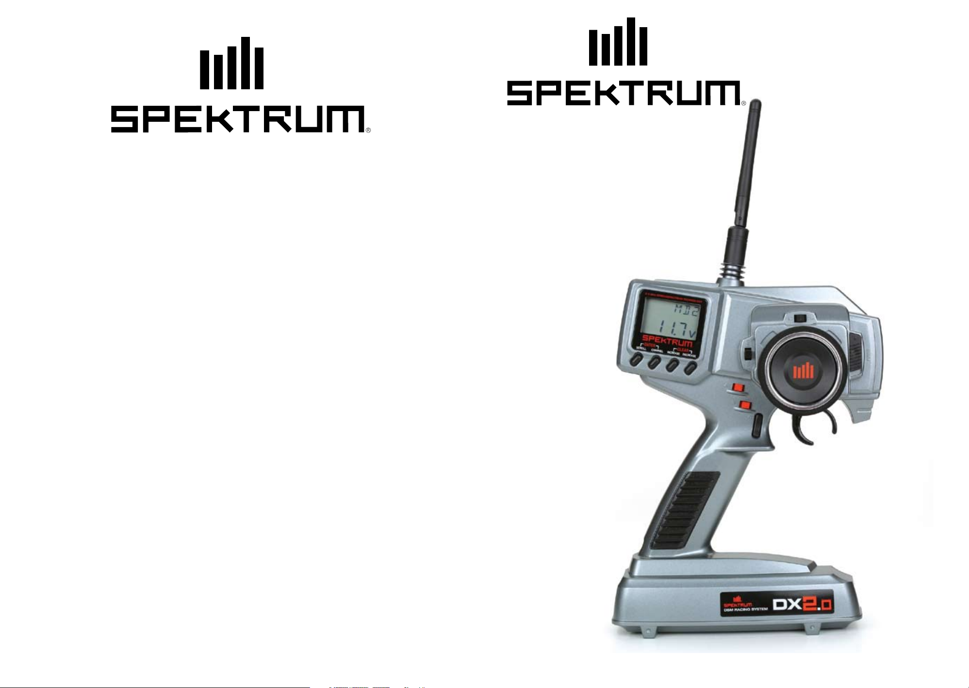
Thank you for purchasing Spektrum’s DX2.0 radio system. The DX2.0 is designed to provide
RC racers with a bulletproof 2.4GHz spread spectrum radio link. With the DX2.0 DSM
system you’ll no longer have to wait for a frequency clip, worry about radio interference from
noisy motors or ESCs or be concerned that someone may turn on a radio on your channel
causing interference. In addition, the DX2.0’s programming is user-friendly and offers the
most important features and functions that racers demand. It’s important that you carefully
read this manual before attempting to operate your DX2.0 system.
For those who would like to get out to the track quickly with just the basic radio setup, please
refer to the Quick Start section that follows.
Included in this manual are in-depth instructions detailing all the steps and procedures
needed to correctly program each of the DX2.0’s features. Quick Start covers the basic
programming information necessary to get you to the track fast. Later, when you want to learn
more about the specific features of the DX2.0, refer to the appropriate page(s) in this manual
for more detailed programming information.
Binding
It’s necessary to program the receiver to a specific transmitter so that the receiver will only
recognize that transmitter, ignoring signals from any other sources. If the receiver is not
bound to a transmitter, the system will not operate. Also, during the binding process, the
servo failsafe positions are set.
1. Make sure the transmitter and receiver are turned off.
2. With the receiver off, insert the bind plug into the BIND port on the receiver.
3. Power the receiver through any port. The green LED will flash continuously, indicating
the receiver is in bind mode.
4. Hold down on the SCROLL and CHANNEL buttons while turning on the transmitter.
To enter System Mode, press the SCROLL button until “BND” appears on the screen.
5. With the steering wheel and the throttle trigger in their desired failsafe positions, press
the INCREASE and DECREASE buttons at the same time to enter bind mode. “BND” will
flash when in bind mode.
6. After several seconds the LED on the receiver will quit flashing and remain solid,
indicating that the binding process was successful. Once binding is complete, the
system will automatically connect.
7. Once the bind process is complete and before power is cycled on the receiver, remove
the bind plug from the receiver and store it in a convenient place. Failure to remove the
bind plug will result in the receiver going back into bind mode.
Page 3
4
5
DX2.0 Quick
Servo Reversing
DX2.0 Quick
Steering and Throttle Trim Adjustment
Start Setup
(continued)
–
st
REV • NORM
–
1. With the transmitter power switch on, press the
SCROLL key to enter the Function mode.
2. Press the SCROLL key until “REV.NORM” appears on the screen.
The “ST” indicates the steering servo reversing screen.
3. Press the INCREASE or DECREASE key to move the cursor
to the desired servo direction (REV.NORM).
4. Press the CHANNEL key once to access the throttle servo reversing screen.
5. To select the direction of the throttle servo, repeat Step 3 above.
Indicates Current Channel
ST = Steering
TH = Throttle
Indicates Current Servo Direction
ENtER
SCROLL
ChaNNEL
Endpoint (Travel) Adjustment
Indicates Current Adjustment Position
STR = Steering Right
STL = Steering Left
FWD = Forward Trigger
BRM = Reverse (brake) Trigger
E P A
–
st
INCREaSE
CLEaR
DECREaSE
Start Setup
(continued)
Direct Trim
Access
TRIM
TRIM
–
STC
0
THC
Indicates Steering
Trim Function
Indicates Current Value
Indicates Throttle
Trim Function
Indicates Current Value
0
Steering Servo Trim Adjustment:
1. With the transmitter power switch on, move the digital steering trim lever in the desired
position to be adjusted. The steering trim value screen will appear automatically.
Throttle Servo Trim Adjustment:
2. With the transmitter power switch on, move the digital throttle trim lever in the desired
position to be adjusted. The throttle trim value screen will appear automatically.
100
1. From the Servo Reverse function, press the SCROLL key once to access
the Endpoint (Travel) Adjustment function (the EPA screen with “ST” will appear).
Indicates Current Value
Steering Adjustment
2. Rotate the steering wheel in the desired direction (left or right) to be adjusted.
3. Press the INCREASE or DECREASE key to select the
desired travel value.
Throttle Adjustment
4. Press the CHANNEL key once. TH will appear on the screen.
5. Pull the trigger for forward or push the trigger for brake adjustment.
6. Press the INCREASE or DECREASE key to select the desired travel value.
Steering Trim
Throttle Trim
Page 4

6
7
DX2.0 with
Digital
Spectrum
Modulation
Binding
The DSM® system operates in the 2.4GHz band (that’s 2400MHz). This high frequency offers
a significant advantage as it’s well out of the range of model-generated radio interference
(like motor and ESC noise). All the complex issues that now exist using 27 and 75MHz
radios with model-generated interfering noise are eliminated with this system. The DSM
system uses Direct Sequencing Spread Spectrum modulation to generate a wide signal on a
single frequency. The FCC requires that these systems be “smart”– incorporating collision
avoidance such that when a system is turned on, it scans the 2.4GHz band and selects a
channel that is not being used, then begins transmitting on that unused channel. 79 channels
are available and the odds of one DSS spread spectrum system interfering with another are
astronomically remote.
During the first installation, the receiver(s) must be bound to the transmitter. Binding is
necessary to program the receiver(s) to distinguish its corresponding transmitter from
others. Also failsafe positions are transferred from the transmitter to the receiver during
binding. (See binding below for more details.)
It is necessary to bind the receiver to the transmitter during the first installation, and is
recommended when the receiver is moved from one vehicle to another. Receivers can be
re-bound to the same transmitter or to other transmitters an infinite number of times. Also
multiple receivers can be bound to a single transmitter, which is common when using one
transmitter to operate several models.
Only bound receivers and transmitters can connect. During power-up, the transmitter
scans for a free channel while the receiver scans for its bound transmitter. When control is
achieved, the LED on the receiver remains on continuously.
Binding
(continued)
Antenna
4. Hold down on the SCROLL and CHANNEL buttons while turning on the transmitter.
To enter System Mode, press the SCROLL button until “BND” appears on the screen.
-
-
b D
M
5. With the steering wheel and the throttle trigger in their desired failsafe positions, press
the INCREASE and DECREASE buttons at the same time to enter bind mode. “BND”
will flash when in bind mode.
6. After several seconds the LED on the receiver will quit flashing and remain solid,
indicating that the binding process was successful. Once binding is complete, the
system will automatically connect.
7. Once the bind process is complete and before power is cycled on the receiver, remove
the bind plug from the receiver and store it in a convenient place. Failure to remove the
bind plug will result in the receiver going back into bind mode.
At 3.6 inches in length, the receiver antenna is significantly shorter than conventional
antennas. Like all antennas, it’s important to mount the antenna vertically. In most cases the
antenna can be mounted inside the body with no loss of range. Mount the receiver antenna
as recommended by the manufacturer of the vehicle, however, it may be necessary to trim the
plastic antenna tube (included with your vehicle).
In the unlikely event that the link is lost during use, the receiver will drive the servos to
their failsafe positions that were preset during the binding process. If the receiver is turned
on prior to turning on the transmitter, the receiver will enter the failsafe mode, driving the
servos to their preset failsafe position. When the transmitter is turned on, normal control is
resumed.
To Bind the Receiver to the Transmitter
1. Make sure the transmitter and receiver are turned off.
LED
2. With the receiver off, insert the bind plug into the BIND port on the receiver.
3. Power the receiver through any port. The green LED will flash continuously, indicating
the receiver is in bind mode.
Page 5

8
9
Receiver
Power System
Requirements
Power
System Test
Guidelines
Inadequate or intermittent power to the receiver that is unable to provide the necessary
minimum voltage during operation is the number one cause of control failures with Spektrum
systems. Some of the power system components that affect the ability to properly deliver
adequate power include:
•Receiverbatterypack(numberofcells,batteryconstructionquality,connectorandstate
of charge)
•TheESC’scapabilitytodelivercurrenttothereceiverandservosinelectricvehicles
•Theswitchharness,batteryleads,servoleads,regulatorsetc.
All Spektrum receivers have a minimum operational voltage of 3.5 volts. If the voltage drops
below 3.5 volts, the system will cease control until power is regained.
If a questionable power system is being used (e.g. small or old battery, ESC that may
not have a BEC that will support the servo’s current draw, etc.), it is recommended that a
voltmeter be used to perform the following test.
Plug the voltmeter into an open channel port in the receiver and with the system on, load
the servos (apply pressure with your hand) while monitoring the voltage at the receiver. The
voltage should remain above 4.8 volts even when all servos are loaded. For gas vehicles, tap
and twist the receiver battery pack while watching the voltmeter. Some battery packs have
poorly welded tabs that give only intermittent power. Such a defect will show up during shock
and vibration, so this test will verify that the battery construction is good.
System
Features
Tips on Using
Spektrum
2.4GHz
•DSM2.4GHzSpreadSpectrumModulation
•NowcompatiblewithDSM2andMarinesurfacereceivers,inadditionto
DSM surface receivers
•Twochannels
•Easy-to-readLCDgraphicsdisplay
•Two-modelmemory
•Three-charactermodelnameentry
•Electronicdigitaltrimleversforthrottleandsteering
•Directdisplaytrimfunction
•Sub-trim
•Steeringrateadjustment
•Independentsteeringendpointadjustments
•Brake/throttleendpointadjustment
•Lowbatteryalarm
•Chargejackreceptacle(rechargeablebatteriesnotincluded;orderJRPB958)
While your DSM equipped 2.4GHz system is intuitive to operate, functioning nearly
identically to 27 and 75MHz systems, following are a few common questions from
customers.
1. Q: Which do I turn on first, the transmitter or the receiver?
Typical Range
Your system’s range can vary greatly due to your installation and the environment. In most
cases you should be able to have full control of your vehicle to the limits of sight (about 300
ft with a 1/10-scale car). If range issues exist your installation can be optimized by extending
the receiver’s antenna as vertically as possible locating it as high in the vehicle as practical
and also by routing the antenna away from any onboard electronics.
A: If the receiver is turned on first—all servos will be driven to their preset failsafe
positions set during binding. When the transmitter is then turned on, the transmitter scans
the 2.4GHz band and acquires an open channel. Then the receiver that was previously bound
to the transmitter scans the band and finds the GUID (Globally Unique Identifier code) stored
during binding. The system then connects and operates normally.
If the transmitter is turned on first—the transmitter scans the 2.4GHz band and acquires
an open channel. When the receiver is then turned on for a short period (the time it takes to
connect) all servos are driven to their preset failsafe positions. The receiver scans the 2.4GHz
band looking for the previously stored GUID and when it locates the specific GUID code
and confirms uncorrupted repeatable packet information, the system connects and normal
operation takes place. Typically this takes 2 to 6 seconds.
2. Q: Sometimes the system takes longer to connect and sometimes it doesn’t connect at all.
A: In order for the system to connect (after the receiver is bound) the receiver must
receive a large number of consecutive uninterrupted perfect packets from the transmitter.
This process is purposely critical of the environment, ensuring that it’s safe to operate when
the system does connect. If the transmitter is too close to the receiver (less than 4 feet) or
if the transmitter is located near metal objects (metal Tx case, the bed of a truck, the top of
a metal workbench, etc.) connection will take longer and in some cases connection will not
occur. The system is receiving reflected 2.4GHz energy from itself and is interpreting this as
unfriendly noise. Moving the system away from metal objects or moving the transmitter
away from the receiver and powering the system again will cause a connection to occur. This
only happens during the initial connection. Once connected, the system is locked in and,
should a loss of signal occur (failsafe), the system connects immediately (4ms) when the
signal is regained.
Page 6
10
11
3. Q: I’ve heard that the DSM system is less tolerant of low voltage. Is that correct?
Control
RC Safety
Precautions
A: All DSM receivers have an operational voltage range of 3.5 to 9.6 volts. With most
systems this is not a problem as most servos cease to operate at around 3.8 volts. When
using multiple high-current draw servos with a single or inadequate battery/ power source,
heavy momentary loads can cause the voltage to dip below this 3.5-volt threshold thus
causing the entire system (servos and receiver) to brown out.
4. Q: Sometimes my receiver loses its bind and won’t connect, requiring rebinding. What
happens if the bind is lost in flight?
A: The receiver will never lose its bind unless it’s instructed to. It’s important to understand
that during the binding process the receiver not only learns the GUID (code) of the
transmitter, but the transmitter learns and stores the type of receiver that it’s bound to.
If the transmitter is placed into bind mode, the transmitter looks for the binding protocol
signal from a receiver. If no signal is present, the transmitter no longer has the correct
information to connect to a specific receiver and in essence the transmitter has been
“unbound” from the receiver.
For safe and reliable performance of your RC model, please carefully read and follow these
guidelines:
1. Radio control models are not toys. They are capable of inflicting serious injury to
people and property. Use caution at all times when operating your model.
2. You are responsible for the safe operation of your RC model. You must properly install,
test and operate your model with a clear sense of that responsibility. Do not take risks
that might endanger yourself or others.
3. Running an RC car in the streets is very dangerous to both drivers and models. Avoid
running your model in areas occupied by full-size automobiles. To locate areas where
you can safely operate your model, you should contact your local hobby shop for RC
tracks or clubs in your area.
4. If at any time while operating your RC model you sense abnormal model functioning,
end your operation immediately. Do not operate your model again until you are certain
the problem has been corrected.
CAUTION: Control of your model is impossible without sufficient voltage for the
transmitter and receiver. A weak transmitter battery will decrease your range of
operation and a weak receiver battery will slow servo movement and decrease
your range of operation. Check your receiver pack voltage often to avoid losing control
of your model.
Identification
and Location
Multidata LCD Display
Digital Voltage Reading
Channel Button
Enter Function
Scroll Button
Increase Button
Clear Function
Decrease Button
Electronic Digital
Throttle Trim Lever
Electronic Digital
Grip Lever A
Electronic Digital
Grip Lever B
Charge Jack
Three Character
Name Input
Grip Button C
Antenna
Electronic Digital
Steering Trim Lever
Power Switch
Steering Wheel
Throttle Trigger
Adjustable
Steering
Tension
Battery Cover *
(8 AA Batteries Required)
Steering
Tension
Adjustment
Steering tension is adjustable via the recessed screw located beneath the steering wheel (see
page 11 for exact location). Turning the screw clockwise increases the steering tension.
* To remove the Battery Cover, press down where it says “press” and push the cover in the
direction of the arrow. Remove the battery cover and install 8 AA batteries in the direction
as molded into the battery holder. If the transmitter voltage fails to register, check for correct
battery installation and review the voltage again.
Page 7

12
13
7.2V Battery
To Motor
Electronic
Speed Controller
Receiver
Servo
Receiver
n
Compatibility
The DX2.0 features DSM technology and is compatible with Spektrum DSM and DSM2
surface receivers and the marine receiver.
COMPATIBLE SPEKTRUM RECEIVERS
The DX2.0 is compatible with the following receivers.
Note: The DX2.0 operates in 16.5ms frame rate.
DSM: SR300 - 3-channel Sport - SPMSR300
SR3000 - 3-channel Standard - SPM1200
SR3001 - 3-channel Pro - SPM1205
SR3300T - 3-channel with built-in telemetry - SPMSR3300T
SR3500 - 3-channel Micro Race - SPM1210
Note: The SR3000HRS (SPM1202) receiver is designed to be used with
Spektrum’s Futaba HRS compatible module system only and is not compatible
with the DX2.0.
DSM2: SR3100 - 3-channel Pro - SPMSR3100
SR3520 - 3-channel Micro Pro - SPMSR3520
Charging Jack
Located on the left-hand side of the transmitter is the charging jack, which accepts only JR
or Spektrum style wall chargers. Please do not attempt to use any other brand of wall charger
as it may be reverse polarity and can cause damage to your system. Only use the JR or
Spektrum type wall charger when the DX2.0 is equipped with NiMH batteries.
Warning: Charge only rechargeable batteries. Non-rechargeable batteries may burst
causing injury to persons and/or damage to property. Risk of fire and electric
shock. Dry location use only.
Charger Pigtail For Transmitter
Black To Positive
Black With White Stripe To Negative
Spektrum Transmitter Charge Jack Polarity
Receiver
Connections
and
Installation
Marine: MR3000 - 3-channel Marine - SPMMR3000
Please note that DSM2 and marine compatible transmitters can be identified by the following
logo located on the back of the transmitter:
Note: When using a separate NiMH receiver as a power source, the operating voltage
range is 4.8–6.0V (4–5 cells) under load.
Attention: Make sure the male and female connectors have the correct polarity (+/–)
before connecting. Be sure to orient the servo plug correctly for proper insertion.
Most electronic speed controllers are set up for BEC (Battery Elimination Circuitry) operation
and plug directly into your receiver. See Figure A for a typical setup and check your speed
controller’s manual for correct installation.
Key Input and
Display
Key Use
SCROLL Used to move up through the available functions
CHANNEL Used to select the desired channel
INCREASE Used to increase the value of the selected function
DECREASE Used to decrease the value of the selected function
To enter the System Mode press the SCROLL
andCHANNEL keys simultaneously and hold
while turning on the transmitter.
ENtER
SCROLL
ChaNNEL
To enter the Function Mode, press the SCROLL
key while the transmitter is on.
Press the INCREASE and DECREASE
keys simultaneously to clear the screen or
return to factory preset.
CLEaR
INCREaSE
DECREaSE
Figure A – Connections to BEC and receiver with electronic speed controller. NiMH battery
speed controller and servos are not included in the radio set.
Page 8

14
15
Display
Screens
Normal Display Screen
When the power switch is turned on, the LCD screen will read as shown below. This screen
is referred to as the Normal Display.
Note: If any of the electronic trim buttons are moved while in this screen, the screen
will automatically change to display the trim in use. This is called the Direct Trim
Mode. For more information on the feature, please see page 5 of this manual.
Accessing the
System Mode
To enter the System Mode, press both the SCROLL and CHANNEL keys at the same time
while turning on the transmitter power switch. By pressing the SCROLL key, you can now
choose Model Select, Model Name Input, Grip Button C function or the Data Reset function
as shown here on the System Mode flow chart. Information for each function is located on
the page number listed next to the function name on the flow chart.
To exit the System Mode, press the SCROLL and CHANNEL keys at the same time, or
simply turn off the transmitter.
-
-
MD1
10.2
Low Battery Screen/Lithium Battery Backup
When the voltage of the eight AA batteries drops below 9.0 volts, the DX2.0’s display
screen will alternate between the Normal (see above) and Low Battery screen (BAT).
A continuous beeping will occur, indicating that the batteries need to be replaced
before further use. The Low Battery screen is active during any operating modes.
v
bat
8.9
Lithium Battery
Your DX2.0 radio system is equipped with a five-year lithium battery backup system.
This system is designed to protect and retain all radio programming in the event that the
transmitter batteries drop below the required 9.0 volts, or the transmitter battery case is
removed during battery changes. If after five years it becomes necessary to replace the
lithium battery, return your system to the Horizon Service Center for repair (see address,
page 28–30).
v
-
-
MDL
I
-
-
MDI
I
GBC
0
–
clr
I
Model Select (Page 16)
Model Name Entry (Page 17)
Grip Button C Function (Page 17)
Data Reset (Page 18)
Memory Backup Screen
If the Memory Backup screen appears, this indicates the possibility of a ROM problem or the
lithium battery is dead. If you switch the power off and on again, and the transmitter is in the
default mode with all data lost, it is strongly suggested that the DX2.0 transmitter be returned
to the Horizon Service Center for servicing (see Warranty Information, page 28–30).
–
bak
–
ER
-
-
b D
M
Bind (Page 6)
RF
RF Mode (Page 18)
Page 9

16
17
Model Select
(System Mode)
The DX2.0 has memory for two models. This feature allows for two different models to be
operated with the same transmitter (additional receivers and servos must be purchased
separately) or one model with two different race setups.
-
-
MDL
Model Select Function
Model Number
I
Accessing the Model Select Function
1. Press the SCROLL and CHANNEL keys at the same time and hold.
2. Turn the transmitter power switch on to enter System Mode.
3. If MDL does not appear on the screen, press the SCROLL key until MDL appears.
4. Press the INCREASE or DECREASE key to select the desired model number
(1 or 2).
5. Press the SCROLL key to access the Model Name Entry Function.
6. To exit the System Mode, either turn the transmitter power switch off or press the
SCROLL and CHANNEL keys at the same time.
Model Name
Entry
(System Mode)
The DX2.0 allows a three-character name to be input for each of the two (2) models available.
The current model, with name, will then be displayed in the Normal display screen. This
feature is useful to help identify different models, setups, etc. For information on selecting
models 1 or 2, please refer to the Model Select Function (page 16).
-
-
MDI
I
Flashing character indicates
the character to be adjusted
Current Model Number
Accessing the Model Name Entry Function
To access the Model Name Entry function, follow the steps below:
1. Press the SCROLL and CHANNEL keys at the same time and hold.
2. Turn on the transmitter power switch to enter the System Mode.
3. Press the SCROLL key until MD1 appears on the screen with the first character
flashing.
4. Press the INCREASE or DECREASE key to select the correct letter/number for the first
character (flashing).
5. To change the remaining two characters, press the CHANNEL key until the desired
character to be changed is flashing.
6. Press the SCROLL key to access the Grip Button C function.
7. To exit the System Mode, either turn the transmitter power switch off or press the
SCROLL and CHANNEL keys at the same time.
The Grip Button C function of the DX2.0 allows you to activate the Emergency Steering
Grip Button C
Function
function. This function allows you to override the steering dual rate giving maximum travel,
which is useful in oval racing. Use the information below to select the correct Grip Button C
assignment for your particular installation.
Select
(System Mode)
GBC
0
Accessing the Model Name Entry Function
1. Press the SCROLL and CHANNEL keys at the same time and hold.
2. Turn on the transmitter power switch to enter the System Mode.
3. Press the SCROLL key until GBC appears on the screen.
4. Press the INCREASE or DECREASE key to select the correct Grip Button C function
type to be used.
5. Press the SCROLL key to access the Data Reset function.
6. To exit the System Mode, either turn the transmitter power switch off or press the
SCROLL and CHANNEL keys at the same time.
Grip Button C Function
Grip Button C is inhibited
Emergency Steering Button
is activated
GBC
E6
Page 10

18
19
Data Reset
(System Mode)
The Data Reset function allows you to reset all the programming in the selected model (1 or
2) to the factory default settings. Before using the Data Reset function, it’s important to enter
the Model Select function and check to make sure the current model number indicated (1 or
2) is the model to which you want to reset to the factory default settings. The Model Select
function is described in detail on page 16.
–
clr
Accessing
the Function
Mode
To enter the Function Mode, turn on the transmitter and then press the SCROLL key. The
display will change to show the first function listed on the Function Mode flow chart as
shown below. Press the SCROLL key to scroll down through the functions one by one, as
shown in the flow chart. Once the desired function has been reached, use the CHANNEL key
to select the appropriate channel (if applicable). To adjust the values of the function, simply
press the INCREASE (+) or DECREASE (-) keys until the desired value is displayed on the
screen. To exit function mode, press the SCROLL and CHANNEL keys at the same time.
The next time you enter Function mode, you will be returned to the last function accessed.
RF Mode
1
Accessing the Data Reset Function
To access the Data Reset function, follow the steps below:
1. Press the SCROLL and CHANNEL keys at the same time and hold.
2. Turn on the transmitter power switch to enter the System Mode.
3. Press the SCROLL key until CLR appears on the screen.
4. Press the INCREASE and DECREASE keys at the same time to reset the data. To
confirm that the selected model’s programming has been reset, a beep will sound and
the model number selected (1 or 2) will stop flashing.
5. To exit the System Mode, either turn the transmitter power switch off or press the
SCROLL and CHANNEL keys at the same time.
The DX2.0 features a selectable RF mode. N is the standard RF mode. FR is the France RF
mode and should only be selected if the transmitter is used in France.
Accessing the RF Mode Function
To access the RF Mode function, follow the steps below:
1. Press the SCROLL and CHANNEL keys at the same time and hold.
2. Turn on the transmitter power switch to enter the System Mode.
3. Press the SCROLL key until RF appears on the screen.
4. Press the INCREASE and DECREASE keys to select the desired RF mode.
5. To exit the System Mode, either turn the transmitter power switch off or press the
SCROLL and CHANNEL keys at the same time.
Indicates model to be reset
E P A
I0 0
TRIM
–
st
–
–
stS
0
–
st
REV • NORM
–
Channel
Key
Channel
Key
Channel
Key
R/BL/F
E P A
TRIM
SB-TRM
tH
I0 0
tHS
0
–
st
REV • NORM
–
–
Endpoint
Adjustment
(page 20)
Sub-Trim
(page 21)
Servo
Reversing
(page 22)
RF
Page 11

20
21
Endpoint
Adjustment
(Function Mode)
The Endpoint Adjustment feature of the DX2.0 allows the maximum travel of both the steering
and throttle servos to be increased or decreased in each direction to achieve the exact servo
movement needed. The Endpoint Adjustment range is from 0% to 125% and is factory set to
100% for both channels. The value displayed on the screen depends on the current position
of the steering wheel, trigger, or trim lever to be adjusted. This feature is very useful either to
maximize servo travel or to reduce servo over-travel to eliminate servo binding (servo moves
further than control mechanism allows), without the need for mechanical linkage adjustment.
The screens below are accessed by turning the wheel to the desired direction to be adjusted
(left or right), by moving the trigger to the forward or backward (brake) position, or by
moving the Grip Lever A to the forward or back position.
L/F
E P A
I0 0
–
st
Steering Left
Endpoint Adj
Current Value
Values: 0 to 125
Clear = 100
L/F
E P A
I0 0
tH
Forward Throttle
Endpoint Adj
Current Value
Values: 0 to 125
Clear = 100
Sub-Trim
(Function Mode)
The Sub-Trim function of the DX2.0 is an electronic trimming feature that allows the neutral
position of the servo on either the steering or throttle channel to be moved, while allowing
the electronic trim lever for that channel to remain in the center position. This feature is very
useful, as it allows the servo arm/wheel position to be moved to help with control linkage
installation, eliminating the need to make mechanical linkage adjustments. Although the
Sub-Trim function is a very useful feature, it is suggested that only small amounts of subtrim be used so that no unwanted, non-equal servo travel is created. It is suggested that less
than 30 points of Sub-Trim be used during adjustment. If more than 30 points of Sub-Trim
are required, it is suggested that a mechanical linkage adjustment be performed.
–0–
TRIM
Values: R/B 125 0 R/F 125
stS
Indicates current channel:
STS = Steering
THS = Throttle
Indicates current value
R/B
E P A
I0 0
–
st
Steering Right
Endpoint Adj
Current Value
Values: 0 to 125
Clear = 100
R/B
E P A
I0 0
tH
Backward Throttle
(Brake)
Endpoint Adj
Current Value
Values: 0 to 125
Clear = 100
Accessing the Endpoint Adjustment Function
1. Turn on the transmitter power switch.
2. Press the SCROLL key to enter Function mode.
3. Press the SCROLL key until EPA appears in small letters on the left side of the screen.
4. Press the CHANNEL key to select the desired channel to be adjusted.
Steering = ST R/B (steering right) or ST L/F (steering left)
Throttle = TH L/F (forward) or TH R/B (braking or reverse)
5. Move the steering wheel or trigger in the desired direction for adjustment (left/right,
forward/reverse or brake). Press the INCREASE or DECREASE key to achieve the
desired amount of travel. Move the wheel or trigger in the opposite direction to adjust
the travel in the opposite direction.
6. Press the SCROLL key to access the Sub-Trim Function.
7. To exit the Function Mode, either turn the transmitter power switch off or press the
SCROLL and CHANNEL keys at the same time.
Note: When setting the endpoint adjustment values for the steering function, it is suggested
that, if possible, the maximum travel values be set to an equal value in both directions to
maintain proper steering control.
Accessing the Sub-Trim Function
1. Turn on the transmitter power switch.
2. Press the SCROLL key to enter the Function Mode.
3. Press the SCROLL key until TRIM appears in small letters to the left of the screen.
4. Press the CHANNEL key to select the channel to be adjusted
(Steering, Throttle).
5. Press the INCREASE or DECREASE key until the proper servo position is achieved.
6. Press the SCROLL key to access the Servo Reversing function.
7. To exit the Function Mode, either turn off the transmitter power switch or press the
SCROLL and CHANNEL keys at the same time.
Page 12

22
23
Servo
Reversing
(Function Mode)
The Servo Reversing feature of the DX2.0 is a very convenient feature when setting up a new
model. The purpose of the Servo Reversing function is to change the direction of the servo
rotation in relation to the wheel/trigger movement. The Servo Reversing function is available
for the steering and throttle of the DX2.0.
–
st
REV • NORM
–
Indicates current channel:
ST = Steering
TH = Throttle
Indicates current servo direction
Accessing the Servo Reversing Function
1. Turn the transmitter power switch on.
2. Press the SCROLL key to access the Function Mode.
3. Press the SCROLL keyuntilREV•NORMappearsinsmallletterstotheright
of the screen.
4. Press the CHANNEL key to select the channel to be changed
(ST = Steering, TH = Throttle).
5. Press the INCREASE or DECREASE key to move the cursor to the desired direction.
6. To exit the Function Mode, either turn off the transmitter power switch or press the
SCROLL and CHANNEL keys at the same time.
Accessing the
Direct Trim
Mode
(Function Mode)
The Direct Trim Mode function of the DX2.0 is accessible through the use of the electronic
throttle or steering trim levers, as well as the two electronic grip levers (A&B) located on
the upper portion of the grip handle. This function allows for quick trim adjustment of these
controls, without the need to access these functions through the four keypad control keys.
To access the Direct Trim Mode function, turn on the transmitter power switch. Next, move
the desired trim lever to be adjusted. The appropriate screen for the selected trim lever will
be displayed. To adjust, simply move the trim lever in the desired direction until the correct
amount of trim is achieved. Once the desired trim is achieved, the screen will return to the
Normal display screen after approximately two seconds from the last trim input. If the
INCREASE or DECREASE key is pressed any time during the two seconds, the system will
return to the previous screen in use.
TRIM
–
stC
Steering Trim
(page 23)
0
Throttle Trim
TRIM
tHC
(page 25)
R/B
RATE
E P A
0
–
stG
70
BRK
50
Steering Dual-Rate
(Grip Lever B)
(page 26)
%
Brake Endpoint
Adjustment
(Grip Lever A)
(page 27)
Page 13

24
25
Steering Trim
(STC)
The DX2.0 electronic Steering Trim lever, located just above the steering wheel, allows the
center position of the servo to be manipulated in either direction to achieve precise centering
of the steering assembly. Steering Travel Endpoint Adjustment values (page 20) remain
completely independent from the steering trim, unless the trim value exceeds the selected
endpoint values. (For example: If trim value is set at 30 and endpoint values at 15, steering
trim will override/alter the endpoint value.)
Throttle Trim
(THC)
The DX2.0’s electronic Throttle Trim lever, located to the left of the steering wheel, allows the
center position of the servo to be manipulated in either direction to achieve precise centering
of the throttle trigger neutral position. Throttle Endpoint adjustment values (page 20) remain
completely independent from the throttle trim, unless the trim value exceeds the selected
endpoint values. (For example: If the trim value is set at 40 and the endpoint values at 30,
Throttle Trim will override/alter the endpoint value.)
–
TRIM
Values: L/F 60 0 R/B 60
Each click will provide 0.3° of trim to the center of the steering servo with a maximum of 12° allowed.
Note: Each click will not always result in a change of the value displayed.
To adjust the steering trim servo position, move the electronic Steering Trim lever either to
the left (+) or the right (-). As soon as the trim is moved, the STC Steering Trim screen will
appear and will continue to be displayed unless the trim lever is untouched for a period of
two seconds. To reset the trim value to 0, press the INCREASE and DECREASE keys at the
same time while the STC screen is displayed.
stC
0
Indicates current value
Steering Trim
–
TRIM
Values: L/F 60 0 R/B 60
To adjust the Throttle Trim servo position, move the electronic steering trim lever either up
(+) or down (-). As soon as the trim is moved, the THC Throttle Trim screen will appear and
will continue to be displayed unless the trim lever is untouched for a period of two seconds.
To reset the trim value to zero, press the INCREASE and DECREASE keys at the same time
while the THC screen is displayed.
Throttle Trim
Increase
Decrease
stC
0
Indicates current value
Throttle Trim Location
Steering Trim Location
Page 14

26
27
Grip Lever B:
Steering Dual
Rate Trim
Adjustment
STG
The Steering Dual Rate Trim Adjustment, located at Grip Lever B, allows the dual rate value
(maximum servo travel) to be increased or decreased within a range from 100% through
20% of the total endpoint value established in the steering EPA function. This function
is very useful in race conditions as it allows you to custom tailor the steering radius and
sensitivity for the current track conditions. Please note that since the Dual Rate value shown
in the STG screen is the percentage of the endpoint value established in the steering EPA
function, the value will not always increase or decrease each time the Grip Lever B is moved.
–
RATE
stG
G r i p L e v e r A :
Brake Endpoint
Adjustment
BRK
The Brake Endpoint Adjustment, located at Grip Lever A, allows the maximum servo travel
on the braking side of the throttle trigger to be increased or decreased from 100% to 0%
(off). This function is very useful in race conditions as it allows the racer to custom tailor
the “panic” brake value to maximize the car’s braking power for the current track conditions.
Please note that since the brake endpoint value shown in the BRK screen is a percentage of
the total braking value established in the Endpoint Adjustment function (page 20), the value
will not always increase or decrease each time the Grip Lever A is moved. To adjust the brake
endpoint value, move the electronic Grip Lever A either left (–) or right (+). As soon as the
grip lever is moved, the BRK Endpoint Adjustment screen will appear and will continue to be
displayed unless the Grip Lever A is untouched for a period of two seconds.
%
70
If the Emergency Steering button function (page 17) is active, pressing Grip Button C will
restore the steering dual rate to 100% until the button is released.
To adjust the Steering Dual Rate value, move the electronic Grip Lever B either left (-) or right
(+). As soon as the trim is moved, the STG Steering Dual Rate screen will appear and will
continue to be displayed unless the Grip Lever B is untouched for a period of two seconds.
To reset the trim value to the factory preset setting of 70%, press the INCREASE and
DECREASE keys at the same time while the STG screen is displayed.
Grip Lever B
Steering
Dual-Rate Trim
Current Value
(20% to 100%)
Decrease
Increase
R/B
E P A
Grip Lever A
Brake Trim
BRK
50
Current Value
(100 to 0%)
Decrease Increase
Move the grip lever A to the left or right to
decrease or increase values.
Page 15

28
29
Warranty
and Service
Information
Warranty Period
Exclusive Warranty- Horizon Hobby, Inc., (Horizon) warranties that the Products
purchased (the “Product”) will be free from defects in materials and workmanship
for a period of 1 year from the date of purchase by the Purchaser.
Limited Warranty
(a) This warranty is limited to the original Purchaser (“Purchaser”) and is
not transferable. REPAIR OR REPLACEMENT AS PROVIDED UNDER THIS
WARRANTY IS THE EXCLUSIVE REMEDY OF THE PURCHASER. This warranty
covers only those Products purchased from an authorized Horizon dealer. Third
party transactions are not covered by this warranty. Proof of purchase is required
for warranty claims. Further, Horizon reserves the right to change or modify this
warranty without notice and disclaims all other warranties, express or implied.
(b) Limitations- HORIZON MAKES NO WARRANTY OR REPRESENTATION,
EXPRESS OR IMPLIED, ABOUT NON-INFRINGEMENT, MERCHANTABILITY OR
FITNESS FOR A PARTICULAR PURPOSE OF THE PRODUCT. THE PURCHASER
ACKNOWLEDGES THAT THEY ALONE HAVE DETERMINED THAT THE PRODUCT
WILL SUITABLY MEET THE REQUIREMENTS OF THE PURCHASER’S INTENDED
USE.
(c) Purchaser Remedy- Horizon’s sole obligation hereunder shall be that Horizon
will, at its option, (i) repair or (ii) replace, any Product determined by Horizon
to be defective. In the event of a defect, these are the Purchaser’s exclusive
remedies. Horizon reserves the right to inspect any and all equipment involved
in a warranty claim. Repair or replacement decisions are at the sole discretion of
Horizon. This warranty does not cover cosmetic damage or damage due to acts of
God, accident, misuse, abuse, negligence, commercial use, or modification of or
to any part of the Product. This warranty does not cover damage due to improper
installation, operation, maintenance, or attempted repair by anyone other than
Horizon. Return of any goods by Purchaser must be approved in writing by
Horizon before shipment.
Damage Limits
HORIZON SHALL NOT BE LIABLE FOR SPECIAL, INDIRECT OR CONSEQUENTIAL
DAMAGES, LOSS OF PROFITS OR PRODUCTION OR COMMERCIAL LOSS IN
ANY WAY CONNECTED WITH THE PRODUCT, WHETHER SUCH CLAIM IS BASED
IN CONTRACT, WARRANTY, NEGLIGENCE, OR STRICT LIABILITY. Further, in
no event shall the liability of Horizon exceed the individual price of the Product
on which liability is asserted. As Horizon has no control over use, setup, final
assembly, modification or misuse, no liability shall be assumed nor accepted for
any resulting damage or injury. By the act of use, setup or assembly, the user
accepts all resulting liability.
If you as the Purchaser or user are not prepared to accept the liability associated
with the use of this Product, you are advised to return this Product immediately in
new and unused condition to the place of purchase.
Law: These Terms are governed by Illinois law (without regard to conflict of law
principals).
Safety Precautions:
This is a sophisticated hobby Product and not a toy. It must be operated with
caution and common sense and requires some basic mechanical ability. Failure
to operate this Product in a safe and responsible manner could result in injury
or damage to the Product or other property. This Product is not intended for
use by children without direct adult supervision. The Product manual contains
instructions for safety, operation and maintenance. It is essential to read and
follow all the instructions and warnings in the manual, prior to assembly, setup or
use, in order to operate correctly and avoid damage or injury.
Questions, Assistance, and Repairs
Your local hobby store and/or place of purchase cannot provide warranty support
or repair. Once assembly, setup or use of the Product has been started, you must
contact Horizon directly. This will enable Horizon to better answer your questions
and service you in the event that you may need any assistance. For questions or
assistance, please direct your email to productsupport@horizonhobby.com, or
call 877.504.0233 toll free to speak to the product support department.
Inspection or Repairs
If this Product needs to be inspected or repaired, please call for a Return
Merchandise Authorization (RMA). Pack the Product securely using a shipping
carton. Please note that original boxes may be included, but are not designed
to withstand the rigors of shipping without additional protection. Ship via a
carrier that provides tracking and insurance for lost or damaged parcels, as
Horizon is not responsible for merchandise until it arrives and is accepted at our
facility. A Service Repair Request is available at www.horizonhobby.com on the
“Support” tab. If you do not have internet access, please include a letter with
your complete name, street address, email address and phone number where you
can be reached during business days, your RMA number, a list of the included
items, method of payment for any non-warranty expenses and a brief summary
of the problem. Your original sales receipt must also be included for warranty
consideration. Be sure your name, address, and RMA number are clearly written
on the outside of the shipping carton.
Warranty Inspection and Repairs
To receive warranty service, you must include your original sales receipt verifying
the proof-of-purchase date. Provided warranty conditions have been met, your
Product will be repaired or replaced free of charge. Repair or replacement
decisions are at the sole discretion of Horizon Hobby.
Non-Warranty Repairs
Should your repair not be covered by warranty the repair will be completed and
payment will be required without notification or estimate of the expense unless
the expense exceeds 50% of the retail purchase cost. By submitting the item
for repair you are agreeing to payment of the repair without notification. Repair
estimates are available upon request. You must include this request with your
repair. Non-warranty repair estimates will be billed a minimum of ½ hour of labor.
In addition you will be billed for return freight. Please advise us of your preferred
method of payment. Horizon accepts money orders and cashiers checks, as well
as Visa, MasterCard, American Express, and Discover cards. If you choose to pay
by credit card, please include your credit card number and expiration date. Any
repair left unpaid or unclaimed after 90 days will be considered abandoned and
will be disposed of accordingly. Please note: non-warranty repair is only available
on electronics and model engines.
Page 16

30
31
United States:
Electronics and engines requiring inspection or repair should be shipped to the
following address:
FCC
Information
This device complies with part 15 of the FCC rules. Operation is subject to the following
two conditions: (1) This device may not cause harmful interference, and (2) this device must
accept any interference received, including interference that may cause undesired operation.
Horizon Service Center
4105 Fieldstone Road
Champaign, Illinois 61822 USA
All other Products requiring warranty inspection or repair should be shipped to
the following address:
Horizon Product Support
4105 Fieldstone Road
Champaign, Illinois 61822 USA
Please call 877-504-0233 or e-mail us at productsupport@horizonhobby.com
with any questions or concerns regarding this product or warranty.
United Kingdom:
Electronics and engines requiring inspection or repair should be shipped to the
following address:
Horizon Hobby UK
Units 1-4 Ployters Rd
Staple Tye
Harlow, Essex
CM18 7NS
United Kingdom
Caution: Changes or modifications not expressly approved by the party responsible for
compliance could void the user’s authority to operate the equipment.
This product contains a radio transmitter with wireless technology which has been tested and
found to be compliant with the applicable regulations governing a radio transmitter in the
2.400GHz to 2.4835GHz frequency range.
Antenna Separation Distance
When operating your Spektrum transmitter, please be sure to maintain a separation distance
of at least 5 cm between your body (excluding fingers, hands, wrists, ankles and feet) and the
antenna to meet RF exposure safety requirements as determined by FCC regulations.
The illustrations below show the approximate 5 cm RF exposure area and typical hand
placement when operating your Spektrum transmitter.
Please call +44 (0) 1279 641 097 or e-mail us at sales@horizonhobby.co.uk with
any questions or concerns regarding this product or warranty.
Germany:
Electronics and engines requiring inspection or repair should be shipped to the
following address:
Horizon Technischer Service
Hamburger Strasse 10
25335 Elmshorn
Germany
Please call +49 4121 46199 66 or e-mail us at service@horizonhobby.de with any
questions or concerns regarding this product or warranty.
CE
Compliance
Information
for the
European
Union
Instructions
for Disposal
of WEEE by
Users in the
European
Union
The associated regulatory agencies of the following countries recognize the noted
certifications for this product as authorized for sale and use.
UK DE DK BG SE FI EE LV LT
PL CZ SK HU RO SI AT IT ES
PT IE NL LU MT CY GR FR
This product must not be disposed of with other waste. Instead, it is the
user’s responsibility to dispose of their waste equipment by handing it over
to a designated collection point for the recycling of waste electrical and
electronic equipment. The separate collection and recycling of your waste
equipment at the time of disposal will help to conserve natural resources
and ensure that it is recycled in a manner that protects human health and the
environment. For more information about where you can drop off your waste
equipment for recycling, please contact your local city office, your household waste disposal
service or where you purchased the product.
Page 17

32
33
Declaration of
No. HH2008111005
Conformity
(in accordance
with ISO/IEC
17050-1)
Product(s): Spektrum DX2.0 Transmitter
Item Number(s): SPM20220E
Equipment class: 2
The objects of declaration described above are in conformity with the requirements of
the specifications listed below, following the provisions of the European R&TTE directive
1999/5/EC:
EN 300-328 v1.7.1 ERM requirements for wideband transmission systems operating
in the 2.4 GHz ISM band
EN 301 489-1 v.1.6.1 General EMC requirements for Radio equipment
EN 301 489-17 v.1.2.1
Signed for and on behalf of:
Horizon Hobby, Inc.
Champaign, IL USA
November 10, 2008
Steven A. Hall
Vice President
International Operations and Risk Management
Horizon Hobby, Inc.
Page 18

34
35
 Loading...