

Page 1

FC6250HX HELICOPTER FLYBARLESS SYSTEM
FC6250HX HUBSCHRAUBER MIT FLYBARLESS-SYSTEM
SYSTÈME SANS BARRE STABILISATRICE POUR HÉLICOPTÈRE FC6250HX
SISTEMA PER ELICOTTERO FLYBARLESS FC6250HX
Page 2

EN
NOTICE
All instructions, warranties and other collateral documents are subject to
change at the sole discretion of Horizon Hobby, LLC. For up-to-date product
literature, visit horizonhobby.com or towerhobbies.com and click on the
support or resources tab for this product.
Meaning of Special Language
The following terms are used throughout the product literature to indicate
various levels of potential harm when operating this product:
WARNING: Procedures, which if not properly followed, create the probability
of property damage, collateral damage, and serious injury OR create a high
probability of super cial injury.
CAUTION: Procedures, which if not properly followed, create the probability
of physical property damage AND a possibility of serious injury.
NOTICE: Procedures, which if not properly followed, create a possibility of
physical property damage AND a little or no possibility of injury.
WARNING: Read the ENTIRE instruction manual to become familiar
with the features of the product before operating. Failure to operate
the product correctly can result in damage to the product, personal property
and cause serious injury.
This is a sophisticated hobby product. It must be operated with caution
and common sense and requires some basic mechanical ability. Failure to
operate this Product in a safe and responsible manner could result in injury
or damage to the product or other property. This product is not intended for
use by children without direct adult supervision. Do not attempt disassembly,
use with incompatible components or augment product in any way without
the approval of Horizon Hobby, LLC. This manual contains instructions for
safety, operation and maintenance. It is essential to read and follow all the
instructions and warnings in the manual, prior to assembly, setup or use, in
order to operate correctly and avoid damage or serious injury.
Age Recommendation: Not for children under 14 years. This is not a toy.
WARNING AGAINST COUNTERFEIT PRODUCTS: Always purchase
from a Horizon Hobby, LLC authorized dealer to ensure authentic
high-quality Spektrum product. Horizon Hobby, LLC disclaims all support and
warranty with regards, but not limited to, compatibility and performance of
counterfeit products or products claiming compatibility with DSM or Spektrum technology.
NOTICE: This product is only intended for use with unmanned, hobby-grade,
remote-controlled vehicles and aircraft. Horizon Hobby disclaims all liability
outside of the intended purpose and will not provide warranty service related
thereto.
2
Page 3
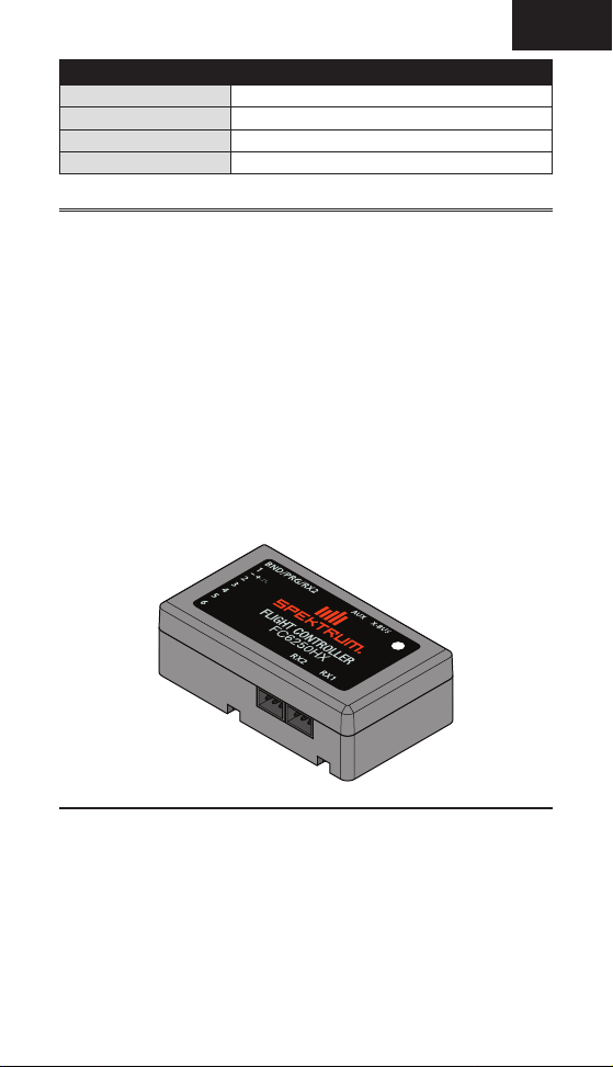
SPMFC6250HX
Type FC6250HX Helicopter Flybarless System
Dimensions (L × W × H) 42.5 x 24 x 13.6mm (1.67 x 0.94 x 0.54in)
Weight 13g (0.46oz)
Voltage Range 4.8V – 8.4V
Spektrum FC6250HX
The Spektrum FC6250HX Flight Controller is a powerful model aircraft stabilization
system that features the latest AS3X® and SAFE Stabilization technology. It features
a leading edge 6-axis M.E.M.S. inertial gyro, powerful and fast 32 bit ARM M4
Cortex processor and proprietary Advanced Adaptive Flight Control Algorithms.
SAFE technology allows pilots to operate within ight modes that automatically
keep the model in a manageable attitude, constantly leveling the model when the
control sticks are returned to center. Additionally, pilots can use SAFE technology
to use a Panic Recovery option. All these features are set up and tuned straight
from a compatible Spektrum transmitter with the Forward Programming menu.
Forward Programming allows you to setup, program, and tune the FC6250HX
ight controller without extra hardware, devices, or computers. Pilots can make
tuning changes on the ight line to the swashplate, tail rotor, SAFE stability, ight
modes and more, from a compatible Spektrum transmitter.
Visit the Spektrum™ USB Programmer and PC programmer application via SpektrumRC.com for updates and changes to the FC6250HX.
EN
Features
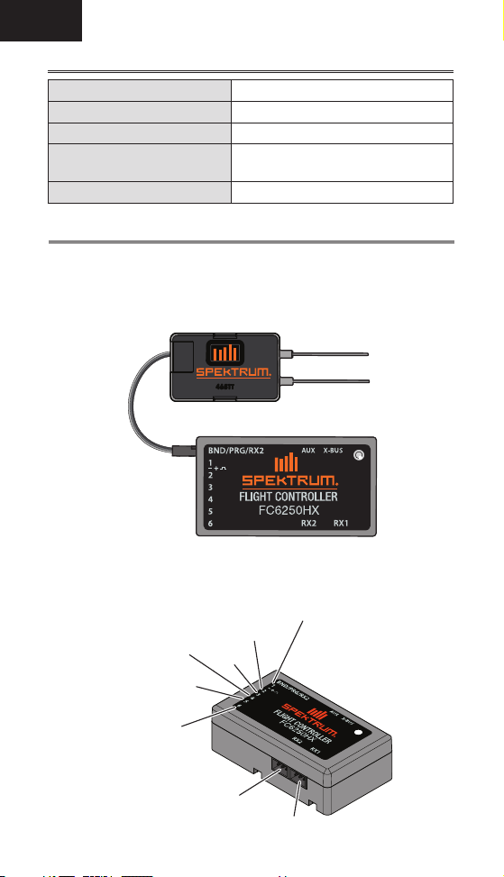
• Includes one SRXL2™ SPM4651T Full Range Telemetry DSMX® Receiver with
bind button
• Supports up to two SRXL2 receivers at 11ms or 22ms
• User con gurable SAFE Panic Recovery and Stability Flight Modes
• Easy to use Forward Programming for setup and gain adjustments from compatible Spektrum Transmitters
• SMART Technology ready for Smart ESC and Battery telemetry
• Supports IX and DX series transmitters
• Supports Digital and Analog servos
• 70Hz to 560Hz Adjustable Servo Frequency (760μs and 1520μs center)
3
Page 4
EN
LED Indications
Red, green, blue rapid blinking Initialization complete
Slow green strobe Normal operation
Slow red strobe Failsafe
Rapid red ash when exiting
forward programming
Slow blue strobe Forward programming mode
Throttle not low; not in Normal/Hold
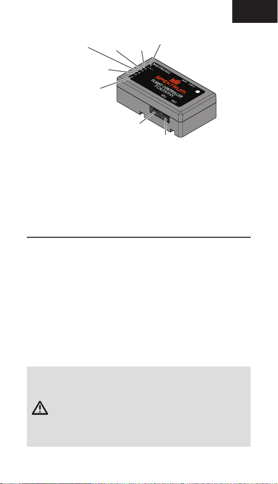
Installation
1. Mount the FC6250HX ight controller with the servo connector block facing
either forward or aft. The side of the FC2650HX facing the main rotor disc
must be parallel to the rotor disc.
2. Use the included mounting tape (SPMA3032) to mount the FC6250HX ight
controller to the airframe.
Connections (Servo and ESC)
Normal Con guration
Servo
C
Tail
Rotor
Servo
Aux1 or
Additional Power
4
Servo
B
RX2
Servo
A
Throttle/
ESC
RX1
Page 5
EN
SMART ESC Con guration
Servo
SMART
Servo
Aux1 or
Additional Power
Remote Receivers
The FC6250HX ight controller uses a SRXL2™ Telemetry Remote to access
Forward Programming as well as other SMART features. For models larger
than 360mm, connect a second SRXL2 remote to the RX1 port.
• SRXL2 remotes can be connected to DATA/BIND/RX2, RX2 or RX1 ports.
• Two SRXL2 telemetry remotes can be used (see diagram above).
• Always ensure the remotes are connected to the transmitter before
ying the model. A solid orange LED on each remote receiver indicates a
successful connection.
Forward Programming
The FC6250HX ight controller is exclusively setup, programmed, and tuned
via the Forward Programming menu on a compatible aircraft Spektrum radio
system (e.g., Spektrum Gen2 DX and the iX series).
Visit spektrumrc.com for an updated list of Forward Programming capable
transmitters and updated transmitter rmware.
• Before entering forward programming, lower the throttle to the full stop
position.
• Before exiting forward programming, lower the throttle to the full stop
position.
TIP: Always exit forward programming before disconnecting the power source
to ensure parameters are saved.
Servo
C
Tail
Rotor
Servo
ESC
B
RX2
A
RX1
NOTICE: Do not connect the swash plate or tail rotor servos until the servo
frequency has been con gured. Failure to do so may result in damage to
the servo and/or your model.
WARNING: Always remove the pinion gear or disconnect the main
drive motor from the ESC to disengage the drive system during initial
setup. The main rotor blades may turn in response to setup changes or
transmitter inputs. Failure to do so could result in serious personal injury or
property damage.
5
Page 6

EN
Binding
1. Power ON the FC6250HX ight controller and press the bind button on each
remote. The remote will begin ashing, indicating it is ready to bind.
2. Press the bind button on your transmitter. Lower the throttle stick to the stop
position and power ON the transmitter.
Once the bind process is complete, the remote receiver LED turns solid
orange, indicating the FC6250HX is ready for setup.
The FC6250HX LED will begin ashing green, indicating a successful bind.
A red ashing LED indicates binding is not successful. Begin the binding
procedure again.
Setup
1. In your transmitter, create a new heli setup as a Normal swash plate type.
Set the Frame Rate to 11ms.
The FC6250HX requires the default new model transmitter con guration.
All channels, other than throttle, must have Reversing set to Normal.
All channels, other than throttle, must have the Subtrim set to 0.
All channels, other than throttle, must have the Travel set to 100/100.
All throttle channel settings occur in the following setup procedures within
the transmitter. If you are using a throttle servo do not connect the servo
until you reach the throttle setup step below.
Con gure your desired ight modes, throttle curves and pitch curves per
the respective manufacturer recommendations for the helicopter, ESC
Engine and Transmitter. Please take note that the collective pitch range will
be setup within the FC6250HX setup instructions below.
Within your transmitter enable the Transmitter Gyro function and select
the“Flight Mode Switch” option. Set each ight mode gain to 75%.
2. In the transmitter menu, select Forward Programming.
The transmitter connects to the ight controller, and a menu list displays.
3. Navigate to the SetuptSwashplatetOutput Setup menu again.
4. Set the Frame Rate to the operating frequency speci ed by your servo
manufacturer.
5. Select the Type menu. Set the swashplate type to match your helicopter’s
con guration. Connect the servos shown on the transmitter and per the
Flight Controller connection diagram.
Select Back, and navigate to the Direction menu.
6. Set the servo reversing to ensure the collective pitch stick moves the
servos in the direction of positive collective.
Select Back to return to the previous menu.
6
Page 7

EN
7. Select the Sub Trim menu. The swashplate servos move to the center
position. Use the sub trim adjustments to ensure the servos are level.
Before exiting the menu, ensure the main rotor blades are at 0 degrees
collective and the swashplate is level in the roll and pitch axis.
Select Back twice to exit the SwashplatetOutput Setup menu.
8. Select the AFR menu. Verify that the roll and pitch cyclic are moving in the
correct direction by moving the cyclic stick.
To reverse an axis, edit the axis value and invert the sign. Once the direc-
tions are correct, center the collective stick (0 degrees).
9. Place a pitch gauge on a main rotor blade and zero it out.
• Align the blade with the roll axis, apply full right cyclic, and adjust the
AFR to 12.5 degrees.
• Align the blade with the pitch axis and zero the pitch gauge. Apply full
aft cyclic, and adjust the AFR to 12.5 degrees.
10. Adjust the Collective AFR to set your desired collective pitch range.
Remove the pitch gauge.
Select Back twice to return to the Setup menu. The swashplate setup is
complete.
11. Navigate to the TailrotortOutput Setup menu.
12. Set the Frame Rate to the operating frequency speci ed by your tail rotor
servo manufacturer.
13. Connect the tail rotor servo to Slot 5 and navigate to the Direction menu.
Move the tail rotor stick on the transmitter to the right and ensure the tail rotor servo is moving the correct direction. If not, reverse the channel direction.
Select Back to return to the previous menu.
14. Select Subtrim to center the tail rotor servo.
Select Back to return to the previous menu.
15. Select the Travel menu.
• Select Left travel. Hold the transmitter tail rotor stick full left, and
adjust travel to ensure full travel.
• Select the Right travel. Hold the transmitter tail rotor stick full right,
and adjust travel to ensure full travel and that no binding occurs.
TIP: 90% to 120% is recommended to achieve optimal ight performance.
Press Back twice to return to the Setup menu. Tailrotor setup is complete.
WARNING: Always remove the pinion gear or disconnect the main
drive motor from the ESC to disengage the drive system during initial
setup. The main rotor blades may turn in response to setup changes or
transmitter inputs. Failure to do so could result in serious personal injury or
property damage.
7
Page 8

EN
16. Exit Forward Programming. Con gure the throttle settings according
to the instructions provided by your ESC/Internal Combustion Engine and
Transmitter manufacturer.
17. Once throttle setup is complete, enter Forward Programming mode, and
select the SetuptThrottletFailsafe menu.
18. Lower the throttle stick to the full stop position, and select Capture to
record the throttle fail safe position.
Select Back to return to the SetuptThrottle menu.
19. Select ThrottletHover
This setting is the throttle point where your model hovers in normal mode,
mainly during takeoff and landing. The ight controller applies special
anti roll over algorithms at or below the throttle setting, helping to make
takeoffs and landings easier. The Stunt 1 and Stunt 2 throttle curves
should be above the hover throttle setting to ensure the roll over mitigation
is disabled in ight.
During the initial setup, you can set ThrottletHover to a high value
and test the model. Once the throttle setting is determined for hovering in
normal mode, set the Hover Throttle value.
Select Back to return to the Setup menu.
20. Select the Gyro SettingstOrientation Menu, and set the mounting ori-
entation to match the FC6250HX mounting orientation on your helicopter.
Once complete, physically move the helicopter on each axis to ensure the
gyros are compensating in the correct direction.
Select Back twice to return to the Setup menu.
21. Select the FM Channel and select Inhibit. After initial test ights, if you
would like to use individual gains per ight mode, set the FM Channel
within the Setup menu.
22. The Gain Channel defaults to the gear channel. This is the transmit-
ter aux gyro gain channel for the tail rotor. Enable the Gyro function on
transmitter and set the gain to 75% for all ight modes.
23. Press Back to exit the forward programming menu, and save the param-
eters.
The FC6250HX ight controller setup is complete.
8
Page 9

Operation
Pre ight Checklist
❏ Inspect the model, wiring, and electrical components.
❏ Activate Normal Flight Mode on the transmitter.
❏ Activate Throttle Hold on the transmitter. Lower the throttle to stop or
idle.
❏ Power ON the transmitter.
❏ Power ON the model, and wait for initialization to complete.
❏ Complete the tailrotor and cyclic tests.
❏ Connect the ight pack to the ESC (electric models).
❏ Verify that all connected remote receivers display a solid orange LED.
❏ Con rm that the transmitter roll, pitch, yaw and collective inputs cor-
respond to the helicopter controls.
❏ Con rm that the FC6250HX is compensating in the correct direction.
❏ Review all operational instructions before ying your model.
❏ Place the model on a level surface for take off.
Post ight Checklist
❏ Disconnect the ight battery (electric models)
❏ Power down the FC6250HX
❏ Always turn the transmitter off last
EN
9
Page 10

EN
Telemetry Flight Log
The transmitter telemetry ightlog will provide the following information.
NOTICE: After a ight, if frame losses higher than 30 occur, evaluate the
remote receiver positioning and ensure the antennas have a clear signal
path to the transmission signal.
To help troubleshoot frame losses and holds, use the Range Test reduced
power function within your transmitter. Review your transmitter manual for
additional instructions.
SMART Technology Telemetry
Spektrum SMART Technology provides telemetry information including battery
voltage and temperature.
A rmware update for your transmitter may be required.
To view SMART Telemetry:
1. The SMART Logo appears under the battery logo on the home page. A
signal bar appears in the top left corner of the screen.
2. Scroll past the servo monitor to view SMART technology screens.
For more information about compatible transmitters, rmware updates,
and how to use the SMART Technology on your transmitter, visit
www.SpektrumRC.com.
10
Page 11

EN
Gain Adjustment
The main Forward Programming displays ight control adjustments under
Swashplate and Tailrotor.
Tip: Adjust gains per ight mode by setting the SetuptFM Channel:
Function in the setup menu. Set the Channel Input Con g in the transmitter
for the selected channel to Flight Mode.
After the tail gains are fairly close, use the transmitter gyro gain function to
adjust the gain for each ight mode.
1. Cyclic P Gain Adjustment (Default 50%)
Higher gain will result in greater stability. Setting the gain too high may
result in random twitches if your model has an excessive level of vibration.
High frequency oscillations may also occur if the gain is set too high.
Lower gain will result in less stability. Too low of a value may result in a less
stable model, particularly outdoors in winds.
If you are located at a higher altitude or in a warmer climate, higher gains
may be bene cial—the opposite is true for lower altitude or colder climates.
2. Cyclic I Gain Adjustment (Default 50%)
Higher gain will result in the model remaining still, but may cause low
frequency oscillations if increased too far.
Lower gain will result in the model drifting slowly.
If you are located at a higher altitude or in a warmer climate, higher gains
may be bene cial—the opposite is true for lower altitude or colder climates.
3. Cyclic D Gain Adjustment (Default 7%)
Higher gain will improve the response rate of your inputs.
If the gain is raised too much, high frequency oscillations may occur.
Lower gain will slow down the response to inputs.
4. Cyclic Response (Default 100%)
Higher cyclic response will result in a more aggressive cyclic response
Lower cyclic response will result in a less aggressive cyclic response.
5. Tailrotor P Gain Adjustment (Default 85%)
Higher gain will result in greater stability. Setting the gain too high may
result in random twitches if your model has an excessive level of vibration.
High frequency oscillations may also occur if the gain is set too high.
Lower gain may result in a decrease in stability. Too low of a value may
result in a less stable model particularly outdoors in winds.
If you are located at a higher altitude or in a warmer climate, higher gains
may be bene cial—the opposite is true for lower altitude or colder climates.
11
Page 12

EN
6. Tailrotor I Gain Adjustment (Default 95%)
Higher gain results in the tail remaining still. If the gain is raised too far, low
speed oscillations may occur.
Lower gain will result in the tail drifting in ight over time.
If you are located at a higher altitude or in a warmer climate, higher gains
may be bene cial—the opposite is true for lower altitude or colder climates.
7. Tailrotor D Gain Adjustment (Default 10%)
Higher gain will improve the response rate to your inputs. If raised too far,
high frequency oscillations may occur.
Lower gain will slow down the response to inputs, but will not have an effect
on stability.
SAFE® Technology
Always complete test ights and gain adjustments before enabling SAFE
Technology features.
Before enabling the stability feature, test the
operation by activating SAFE Panic Recovery
function in ight with the transmitter sticks
centered. The model should return to within 4
degrees of level.
NOTICE: High levels of vibration can lead to attitude estimation errors.
When SAFE Panic Recovery is activated, if the model is outside of 4 degrees
of level, evaluate the model for vibration and, if necessary, perform the
calibration step.
The SAFE Panic Recovery function is activated by setting up the following mix
within the transmitter:
Mixing
P-Mix 1 Normal
To activate the SAFE Panic Recovery function, move the collective stick to the
center position and press the bind button (switch I) on your transmitter.
The SAFE Stability function can be enabled within the forward programming
SAFE menu. All gains, ight mode setup, envelope and gain settings are available within the SAFE menu. To enable or disable the stability function per ight
mode set the FM Channel to the appropriate channel within the Setup menu.
Channels Ger > Gyr
Rate 125%/0%
Offset –100%
Switch Switch I
Position 0
1
12
Page 13

EN
Calibration
The FC6250HX is calibrated at the factory. Recalibrate the unit if the panic
or stability functions do not return to level or if there is a slow drift in the roll,
pitch, or yaw axis:
1. Level the model using a bubble level on the roll and pitch axis, power on and
initialize the system.
Bubble Level
Foam Blade
Holder
2. Go to the System Setup menu and select Calibrate.
3. Select Apply.
A red ashing light during calibration indicates the model is either not level
or not stationary. Level the model, taking care to keep it still.
A yellow ashing light during calibration indicates the calibration is
proceeding normally.
4. After the calibration is successful, the LED ashes green.
Troubleshooting Guide
Problem Possible Cause Solution
Helicopter will
not bind to the
transmitter (during binding)
Helicopter will
not link to the
transmitter (after
binding)
Flight controller
will not initialize
Low ight battery or transmitter battery voltage
Transmitter is not in bind
mode
Transmitter too close to the
helicopter during binding
process
Helicopter is bound to a
different model memory
(ModelMatch
Flight battery/Transmitter
battery charge is too low
Helicopter was moved during
initialization
Transmitter is powered off Power on the transmitter
Controls are not centered
™
radios only)
Fully charge or replace the ight battery and/
or transmitter batteries
Power on the transmitter while holding the
Trainer/Bind switch. Hold the Trainer/Bind
switch until binding is complete
Power off the transmitter. Move the transmitter further away from the helicopter.
Disconnect and reconnect the ight battery to the helicopter and follow binding
instructions
Disconnect the ight battery. Select the
correct model memory on the transmitter.
Reconnect the ight battery
Replace or recharge batteries
If windy, lay helicopter on its side during
initialization
Center elevator, aileron and rudder controls.
Make sure the throttle is at idle
13
Page 14

EN
Troubleshooting Guide
Problem Possible Cause Solution
Helicopter will
not respond to
the throttle but
responds to
other controls
Helicopter power
is lacking
Helicopter will
not lift off
Helicopter tail
spins out of
control
Helicopter
wobbles in ight
Throttle not at idle and/or
throttle trim is too high
Transmitter is not in normal
mode or throttle hold is on
Motor is not connected to the
ESC or the motor wires are
damaged
Flight battery charge is
too low
Throttle channel is reversed Reverse the throttle channel on the transmitter
Flight battery has low voltage Fully charge the ight battery
Flight battery is old or damaged Replace the ight battery
Flight battery cells are unbal-
anced
Excessive current is being
drawn through the BEC
Tail drive belt tension is not
correct
Main rotor head is not spin-
ning in the correct direction
Transmitter settings are not
correct
Flight battery has low voltage Fully charge the ight battery
Main rotor blades are in-
stalled backwards
Rudder control and/or sensor
direction reversed
Tail servo is damaged
Inadequate control arm throw
Tail belt is too loose
Cyclic gain is too high
Headspeed is too low
Dampers are worn Replace the main rotor head dampers
Lower the throttle stick and lower the
throttle trim
Verify the transmitter is in normal mode and
throttle hold is off
Connect the motor wires to the ESC and
check motor wires for damage
Replace or recharge ight battery
Fully charge the ight battery, allowing the
charger time to balance the cells
Check all servos and the helicopter motor
for damage
See “Tail Belt Tension” section in this manual
Make sure the main rotor head is spinning
clockwise. Refer to the motor control test
Check throttle and pitch curve settings and
pitch control direction
Install the main rotor blades with the thicker
side as the leading edge
Make sure the rudder control and the rudder
sensor are operating in the correct direction
Check the rudder servo for damage and
replace if necessary
Check the rudder control arm for adequate
travel and adjust if necessary
Make sure the tail drive belt tension is
adjusted correctly
Tuning options using forward programming
are available under the “Advanced Settings”
section in this manual
Increase the helicopter’s head speed via
your transmitter settings and/or using a
freshly charged ight pack
14
Page 15

EN
1-YEAR LIMITED WARRANTY
What this Warranty Covers — Horizon Hobby, LLC, (Horizon) warrants to the
original purchaser that the product purchased (the “Product”) will be free from
defects in materials and workmanship for a period of 1 year from the date of
purchase.
What is Not Covered
This warranty is not transferable and does not cover (i) cosmetic damage, (ii)
damage due to acts of God, accident, misuse, abuse, negligence, commercial
use, or due to improper use, installation, operation or maintenance, (iii) modi cation of or to any part of the Product, (iv) attempted service by anyone other than
a Horizon Hobby authorized service center, (v) Product not purchased from an
authorized Horizon dealer, (vi) Product not compliant with applicable technical
regulations, or (vii) use that violates any applicable laws, rules, or regulations.
OTHER THAN THE EXPRESS WARRANTY ABOVE, HORIZON MAKES NO OTHER
WARRANTY OR REPRESENTATION, AND HEREBY DISCLAIMS ANY AND ALL
IMPLIED WARRANTIES, INCLUDING, WITHOUT LIMITATION, THE IMPLIED WARRANTIES OF NON-INFRINGEMENT, MERCHANTABILITY AND FITNESS FOR A
PARTICULAR PURPOSE. THE PURCHASER ACKNOWLEDGES THAT THEY ALONE
HAVE DETERMINED THAT THE PRODUCT WILL SUITABLY MEET THE REQUIREMENTS OF THE PURCHASER’S INTENDED USE.
Purchaser’s Remedy — Horizon’s sole obligation and purchaser’s sole and
exclusive remedy shall be that Horizon will, at its option, either (i) service, or (ii)
replace, any Product determined by Horizon to be defective. Horizon reserves
the right to inspect any and all Product(s) involved in a warranty claim. Service or
replacement decisions are at the sole discretion of Horizon. Proof of purchase is
required for all warranty claims. SERVICE OR REPLACEMENT AS PROVIDED UNDER THIS WARRANTY IS THE PURCHASER’S SOLE AND EXCLUSIVE REMEDY.
Limitation of Liability — HORIZON SHALL NOT BE LIABLE FOR SPECIAL,
INDIRECT, INCIDENTAL OR CONSEQUENTIAL DAMAGES, LOSS OF PROFITS OR
PRODUCTION OR COMMERCIAL LOSS IN ANY WAY, REGARDLESS OF WHETHER
SUCH CLAIM IS BASED IN CONTRACT, WARRANTY, TORT, NEGLIGENCE, STRICT
LIABILITY OR ANY OTHER THEORY OF LIABILITY, EVEN IF HORIZON HAS BEEN
ADVISED OF THE POSSIBILITY OF SUCH DAMAGES. Further, in no event shall the
liability of Horizon exceed the individual price of the Product on which liability is
asserted. As Horizon has no control over use, setup, nal assembly, modi cation
or misuse, no liability shall be assumed nor accepted for any resulting damage or
injury. By the act of use, setup or assembly, the user accepts all resulting liability.
If you as the purchaser or user are not prepared to accept the liability associated
with the use of the Product, purchaser is advised to return the Product immediately in new and unused condition to the place of purchase.
Law — These terms are governed by Illinois law (without regard to con ict of law
principals). This warranty gives you speci c legal rights, and you may also have
other rights which vary from state to state. Horizon reserves the right to change or
modify this warranty at any time without notice.
WARRANTY SERVICES
Questions, Assistance, and Services —
of purchase cannot provide warranty support or service. Once assembly, setup or
use of the Product has been started, you must contact your local distributor or Horizon directly. This will enable Horizon to better answer your questions and service
you in the event that you may need any assistance. For questions or assistance,
Your local hobby store and/or place
15
Page 16

EN
please visit our website at www.horizonhobby.com, submit a Product Support Inquiry, or call the toll free telephone number referenced in the Warranty and Service
Contact Information section to speak with a Product Support representative.
Inspection or Services — If this Product needs to be inspected or serviced and
is compliant in the country you live and use the Product in, please use the Horizon
Online Service Request submission process found on our website or call Horizon
to obtain a Return Merchandise Authorization (RMA) number. Pack the Product
securely using a shipping carton. Please note that original boxes may be included,
but are not designed to withstand the rigors of shipping without additional protection. Ship via a carrier that provides tracking and insurance for lost or damaged
parcels, as Horizon is not responsible for merchandise until it arrives and is accepted at our facility. An Online Service Request is available at http://www.horizonhobby.com/content/service-center_render-service-center. If you do not have
internet access, please contact Horizon Product Support to obtain a RMA number
along with instructions for submitting your product for service. When calling
Horizon, you will be asked to provide your complete name, street address, email
address and phone number where you can be reached during business hours.
When sending product into Horizon, please include your RMA number, a list of the
included items, and a brief summary of the problem. A copy of your original sales
receipt must be included for warranty consideration. Be sure your name, address,
and RMA number are clearly written on the outside of the shipping carton.
NOTICE: Do not ship LiPo batteries to Horizon. If you have any issue with
a LiPo battery, please contact the appropriate Horizon Product Support
of ce.
Warranty Requirements — For Warranty consideration, you must include your
original sales receipt verifying the proof-of-purchase date. Provided warranty conditions have been met, your Product will be serviced or replaced free of charge.
Service or replacement decisions are at the sole discretion of Horizon.
Non-Warranty Service — Should your service not be covered by warranty,
service will be completed and payment will be required without noti cation or estimate of the expense unless the expense exceeds 50% of the
retail purchase cost. By submitting the item for service you are agreeing
to payment of the service without noti cation. Service estimates are available upon request. You must include this request with your item submitted
for service. Non-warranty service estimates will be billed a minimum of ½
hour of labor. In addition you will be billed for return freight. Horizon accepts
money orders and cashier’s checks, as well as Visa, MasterCard, American
Express, and Discover cards. By submitting any item to Horizon for service,
you are agreeing to Horizon’s Terms and Conditions found on our website
http://www.horizonhobby.com/content/service-center_render-service-center.
ATTENTION: Horizon service is limited to Product compliant in the
country of use and ownership. If received, a non-compliant Product
will not be serviced. Further, the sender will be responsible for arranging return shipment of the un-serviced Product, through a carrier
of the sender’s choice and at the sender’s expense. Horizon will hold
non-compliant Product for a period of 60 days from noti cation, after
which it will be discarded.
10/15
16
Page 17

EN
Warranty and Service Contact Information
Country of
Purchase
United States
of America
Horizon Hobby Contact Information Address
Horizon Service
EU
Center
(Repairs and Repair
Requests)
Horizon Product
Support
(Product Technical
Assistance)
Sales
Horizon Technischer
Service
Sales: Horizon
Hobby GmbH
servicecenter.horizonhobby.com/
RequestForm/
productsupport@
horizonhobby.com
877-504-0233
websales@horizonhobby.com
800-338-4639
service@horizonhobby.eu
+49 (0) 4121 2655 100
2904 Research Rd
Champaign, Illinois,
61822 USA
Hanskampring 9
D 22885 Barsbüttel,
Germany
FCC Information
This device complies with part 15 of the FCC rules. Operation is subject to the
following two conditions: (1) This device may not cause harmful interference,
and (2) this device must accept any interference received, including
interference that may cause undesired operation.
CAUTION: Changes or modi cations not expressly approved by the
party responsible for compliance could void the user’s authority to
operate the equipment.
This product contains a radio transmitter with wireless technology which
has been tested and found to be compliant with the applicable regulations
governing a radio transmitter in the 2.400GHz to 2.4835GHz frequency range.
Supplier’s Declaration of Conformity
Spektrum Heli Flight Controller (SPMFC6250HX)
This device complies with part 15 of the FCC Rules. Operation is
subject to the following two conditions: (1) This device may not cause
harmful interference, and (2) this device must accept any interference received,
including interference that may cause undesired operation.
CAUTION: Changes or modi cations not expressly approved by the
party responsible for compliance could void the user’s authority to
operate the equipment.
NOTE: This equipment has been tested and found to comply with the limits
for a Class B digital device, pursuant to part 15 of the FCC Rules. These limits
are designed to provide reasonable protection against harmful interference
in a residential installation. This equipment generates, uses and can radiate
radio frequency energy and, if not installed and used in accordance with
the instructions, may cause harmful interference to radio communications.
However, there is no guarantee that interference will not occur in a particular
installation. If this equipment does cause harmful interference to radio or
television reception, which can be determined by turning the equipment off and
on, the user is encouraged to try to correct the interference by one or more of
the following measures:
17
Page 18

EN
• Reorient or relocate the receiving antenna.
• Increase the separation between the equipment and receiver.
• Connect the equipment into an outlet on a circuit different from that to which
the receiver is connected.
• Consult the dealer or an experienced radio/TV technician for help.
Horizon Hobby, LLC
2904 Research Rd.
Champaign, IL 61822
Email: compliance@horizonhobby.com
Web: HorizonHobby.com
IC Information
This device complies with Industry Canada licence-exempt RSS standard(s).
Operation is subject to the following two conditions: (1) this device may not
cause interference, and (2) this device must accept any interference, including
interference that may cause undesired operation of the device.
Compliance Information for the European Union
EU Compliance Statement: Horizon Hobby, LLC hereby
declares that this product is in compliance with the essential
requirements and other relevant provisions of the RED directive.
A copy of the EU Declaration of Conformity is available online at:
http://www.horizonhobby.com/content/support-render-compliance.
Instructions for disposal of WEEE by users in the
European Union
This product must not be disposed of with other waste. Instead,
it is the user’s responsibility to dispose of their waste equipment
by handing it over to a designated collections point for the
recycling of waste electrical and electronic equipment. The
the time of disposal will help to conserve natural resources and ensure that
it is recycled in a manner that protects human health and the environment.
For more information about where you can drop off your waste equipment for
recycling, please contact your local city of ce, your household waste disposal
service or where you purchased the product.
separate collection and recycling of your waste equipment at
18
Page 19

IT
© 2020 Horizon Hobby, LLC. Blade, DSMX, AS3X, SAFE, and SRXL2 are
trademarks or registered trademarks of Horizon Hobby, LLC. The Spektrum
All other trademarks, service marks and logos are property of their respective owners.
Created 11/19 62400
trademark is used with permission of Bachmann Industries, Inc.
US 9,930,567. US 10,419,970. US 9,056,667. US 9,753,457. US 10,078,329.
72
 Loading...