

Page 1

4-Channel 2.4GHz DSMR™ System
Instruction Manual
Bedienungsanleitung
Manuel d’utilisation
Manuale di istruzioni
Page 2
EN
NOTICE
All instructions, warranties and other collateral documents are subject to change at the sole discretion of Horizon Hobby, Inc.
For up-to-date product literature, visit horizonhobby.com and click on the support tab for this product.
MEANING OF SPECIAL LANGUAGE
The following terms are used throughout the product literature to indicate various levels of potential harm when operating this
product:
NOTICE: Procedures, which if not properly followed, create a possibility of physical property damage AND little or no possibility of
injury.
CAUTION: Procedures, which if not properly followed, create the probability of physical property damage AND a possibility of
serious injury.
WARNING: Procedures, which if not properly followed, create the probability of property damage, collateral damage and serious
injury OR create a high probability of superficial injury.
WARNING: Read the ENTIRE instruction manual to become familiar with the features of the product before operating.
Failure to operate the product correctly can result in damage to the product, personal property and cause serious injury.
This is a sophisticated hobby product. It must be operated with caution and common sense and requires some basic mechanical
ability. Failure to operate this Product in a safe and responsible manner could result in injury or damage to the product or other
property. This product is not intended for use by children without direct adult supervision. Do not attempt disassembly, use with
incompatible components or augment product in any way without the approval of Horizon Hobby, Inc. This manual contains
instructions for safety, operation and maintenance. It is essential to read and follow all the instructions and warnings in the manual,
prior to assembly, setup or use, in order to operate correctly and avoid damage or serious injury.
WARNING AGAINST COUNTERFEIT PRODUCTS
Always purchase from a Horizon Hobby, Inc. authorized dealer to ensure authentic high-quality Spektrum product. Horizon
Hobby, Inc. disclaims all support and warranty with regards, but not limited to, compatibility and performance of counterfeit
products or products claiming compatibility with DSM or Spektrum.
NOTICE: This product is only intended for use with unmanned, hobby-grade, remote-controlled vehicles and aircraft. Horizon
Hobby disclaims all liability outside of the intended purpose and will not provide warranty service related thereto.
Age Recommendation: Not for Children under 14 years. This is not a toy.
WARRANTY REGISTRATION
Visit community.spektrumrc.com today to register your product.
SAFETY PRECAUTIONS
• Always ensure all batteries have been properly charged
prior to using the model.
• Always check all servos and their connections prior to each run.
• Never operate your model near spectators, parking areas or
any other area that could result in injury to people or damage of property.
• Never operate your model during adverse weather conditions. Poor visibility can cause disorientation and loss of
control of your model.
• Never point the transmitter antenna directly toward the
model. The radiation pattern from the tip of the antenna is
inherently low.
• If at any time during the operation of your model you
observe any erratic or abnormal operation, immediately stop
operation of your model until the cause of the problem has
been ascertained and corrected.
2
Spektrum DX4S • tranSmitter inStruction manual
Page 3

Building on the success of the DX3S transmitter, the Spektrum™ DX4S transmitter with DSMR™ protocol brings you even more
features, including pre-programmed steering mixes, full switch assignability and a convenient back-lit display. Spektrum DSMR
technology is an exclusive, frequency-agile 2.4GHz protocol that provides surface RC vehicles and boats with superb range and response. This is particularly true in environments where many other 2.4GHz transmitters are in use at the same time. Spektrum DSMR
transmitters are also backwards compatible with DSM®, DSM2® and Marine-specific Spektrum receivers.
TABLE OF CONTENTS
EN
Warranty Registration .................................................2
Identifying Controls and Switches ...............................4
Installing Batteries ......................................................4
Installing Optional Li-Po Battery Pack ......................5
Changing the Rubber Grip ...........................................5
Updating the Firmware ..............................................5
ModelMatch................................................................5
Warning Screens ........................................................6
Low Battery Alarm ..................................................6
Inactivity Alarm .......................................................6
Main Screen ...............................................................6
Programming Guide ....................................................6
Individual Direction Adjustments .................................7
List ............................................................................7
Model Select ...........................................................7
Copy .......................................................................7
Reverse ..................................................................8
Travel ......................................................................8
Exponential ............................................................8
Receiver Compatibility ................................................9
Electric Vehicle Installation ....................................10
Typical Nitro Vehicle Installation ............................10
Failsafe .................................................................10
Bind Transmitter to Receiver .................................10
Sub-Trim ...............................................................11
Timer ...................................................................12
Switch ..................................................................12
Mixing ...................................................................13
Motor On Axle (MOA) Throttle Mix ..........................14
Active Vehicle Control (AVC) ...................................15
Servo Speed .........................................................16
ABS (Automatic Breaking System or pulse brakes) 16
Trim Step .............................................................16
Throttle Punch ......................................................17
Reset ....................................................................17
Monitor .................................................................17
System ................................................................18
Telemetry ..............................................................19
Troubleshooting Guide ..............................................20
FCC Information ........................................................20
Antenna Separation Distance ....................................20
Warranty and Repair Policy .......................................21
Warranty and Service Contact Information ................22
Declaration of Conformity .........................................23
European Union Information ......................................23
Spektrum DX4S • tranSmitter inStruction manual
3
Page 4
EN
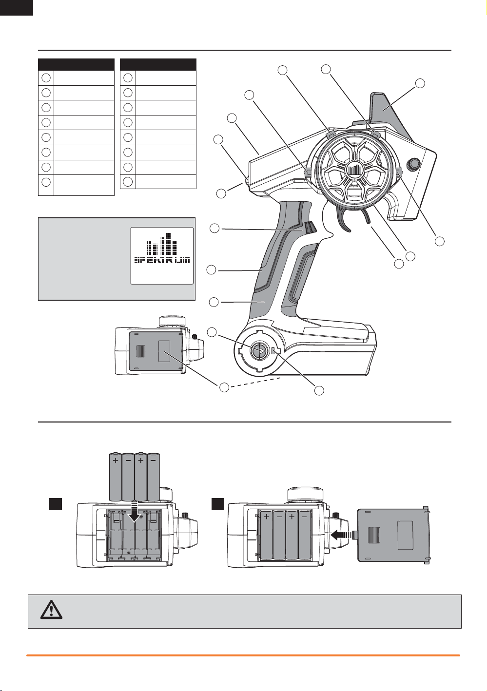
IDENTIFYING CONTROLS AND SWITCHES
Function
A
Switch A
B
Switch B
C
Switch C
D
Switch D
E
Switch E
F
Switch F
G
Roller Selector
Memory Card Port
H
(under rubber grip)
Press the power switch (J)
to power ON the transmitter. The Power LED (K) will
come on, a Spektrum logo
screen will show, then the
Main Screen will show on
the LCD screen (P).
I
Rubber Grip
J
Power Switch
K
Power LED
L
Battery Cover
M
Throttle Trigger
N
Steering Wheel
O
Antenna
P
LCD Screen
Function
B
A
P
F
G
E
H
I
J
C
O
D
N
M
INSTALLING BATTERIES
1
CAUTION: NEVER remove the transmitter batteries while the model is powered on. Loss of model control, damage or injury
may occur.
4
L
K
2
Spektrum DX4S • tranSmitter inStruction manual
Page 5
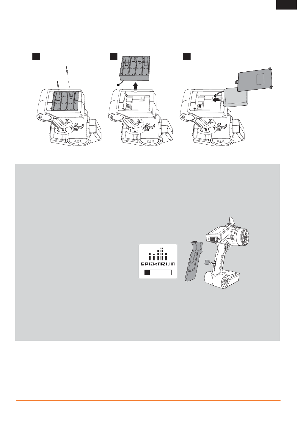
Installing Optional Li-Po Battery Pack
IMPORTANT: Set the transmitter battery type to LiPo in the System/Alert menu and ensure the battery voltage alert is set to the
proper voltage. See the System section for more details.
1 2 3
Changing the Rubber Grip
This transmitter includes 3 sizes of grips. The medium-size grip is installed at the factory. Inside the grip is a letter size:
L for large, M for medium and S for small.
To change the rubber grip:
1. Lift the edge of the grip and pull the grip away from the handle.
2. Align the tabs on the new grip with the slots in the handle.
3. Press the grip against the handle.
EN
Updating the Firmware
The DX4S features an SD card reader, enabling you to update the transmitter when firmware updates are available.
Register your transmitter at
Community.SpektrumRC.com to receive the latest information regarding firmware updates. To install firmware updates
on your DX4S transmitter:
1. Remove the grip from the back of the transmitter handle.
2. Download the latest firmware from
Community.SpektrumRC.com to an SD card. The transmitter serial number can be found by going to the About screen.
3. Install the SD card in the card reader slot on the DX4S transmitter.
4. Power on the transmitter. A Spektrum logo and an installation bar will appear. Installation is complete when the Main screen appears.
5. Remove the SD card from the card slot on the transmitter.
6. Reinstall the rubber grip on the transmitter handle.
ModelMatch
The Spektrum DX4S transmitter features ModelMatch™ technology, preventing you from operating a vehicle when the wrong model
memory is active in the transmitter. If you select the wrong model memory, the receiver will not respond to the transmitter.
Spektrum DX4S • tranSmitter inStruction manual
5
Page 6
EN
Turn
Press
Press
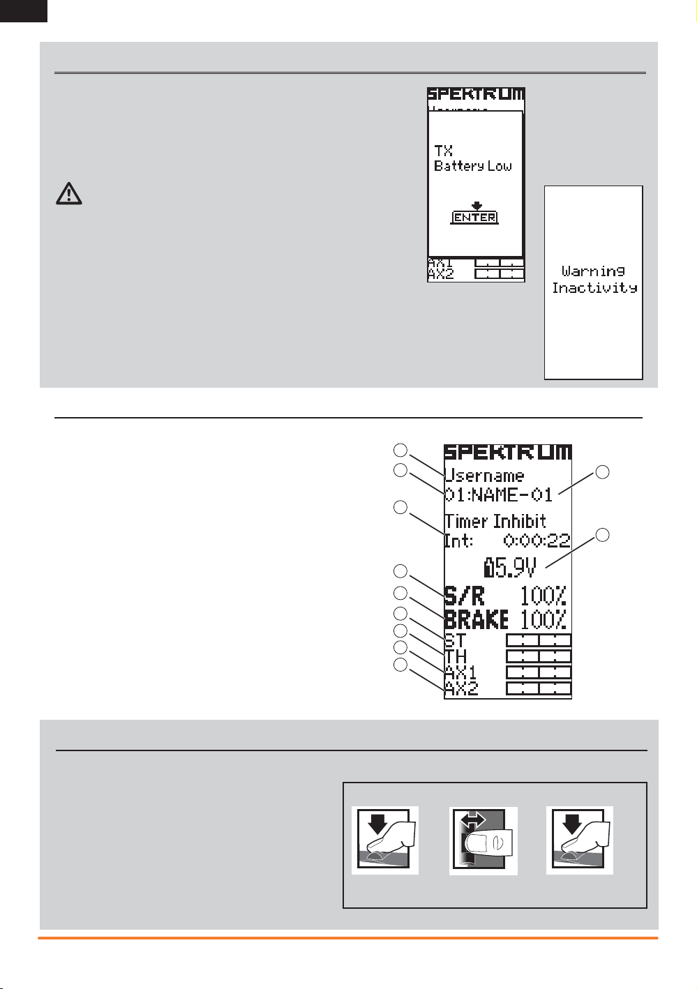
WARNING SCREENS
Low Battery Alarm
An alarm will sound and a warning screen will show when the transmitter’s battery power falls below a set limit. This alarm reminds the user to bring the model
under full control, power off the transmitter and replace the batteries. Press the
Roller to stop the alarm and go to the Main Screen.
Set the low battery limit using the System Screen.
CAUTION: If you decide to use the optional Li-Po battery back, never allow
the battery voltage to fall below 6.4V.
A Warning title
B Battery voltage, which is under the set limit
C Animated arrow pointing to Roller below the screen
D Image of roller below the screen.
Inactivity Alarm
The alarm reminds users to power off the transmitter and save battery power. If the transmitter is powered
on for more than 10 minutes and no control movement is detected, the inactivity alarm will activate. Moving any control stops the alarm. After one hour of inactivity, the transmitter will automatically shut down to
save battery life. To turn the transmitter on again, push the power button off, then on.
MAIN SCREEN
The Main Screen displays information about the active model,
including the Timer (when activated).
To return to the Main Screen at any time, press and hold the
Rolling Selector for at least 3 seconds.
A
B
C
A User Name
B Active Model memory number (30 available)
C Name assigned to the Model memory
D Timer (when activated)
E Transmitter battery voltage
F Steering Percent
G Brake Percent
H Position of Steering (St) trim
I Position of Throttle (Th) trim
J Position of Aux 1 trim
K Position of Aux 2 trim
PROGRAMMING GUIDE
Using the Rolling Selector
Press the Selector to enter a highlighted function.
Roll the Selector to highlight a function, or change settings and
values when selected.
Press and hold the Selector for more than 3 seconds in any
screen to return the display to the List Screen or the Main
Screen.
To program, always start with a press on the Selector, then roll,
then press, then roll, and so on.
D
F
G
H
I
J
K
Press
To Enter, Choose or Exit
a selection.
Roll
To move between options or
change values in an option.
E
Hold
Hold for 3 seconds and release
to return to the Main or
Telemetry screen.
6
Spektrum DX4S • tranSmitter inStruction manual
Page 7
EN
Individual Direction Adjustments
In some instances, you may find it necessary to independently
adjust the control directions; for example, if you want more
travel for left steering than right steering, perform the following
steps:
1. Scroll to the value you wish to change and press the Rolling
Selector.
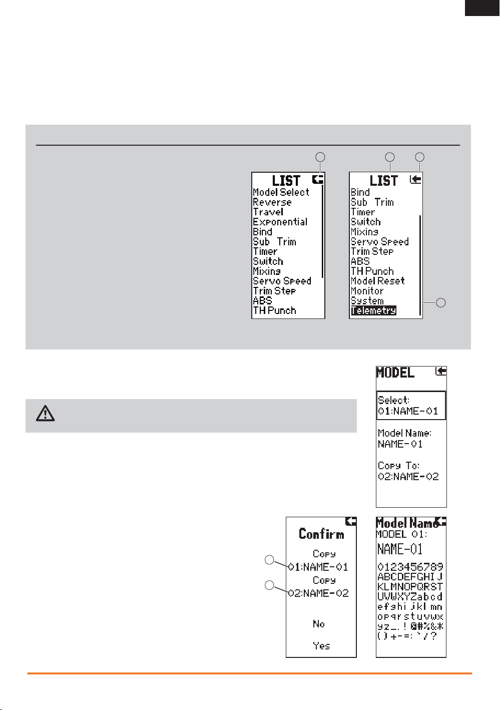
LIST
The List Screen shows other screens to set programming in the
transmitter.
· A dark box (A) with a clear symbol or text represents the
highlighted selection.
· The Active Screen name (B) is displayed at the top of
the screen.
· Choosing this arrow (C) will open the next higher screen,
such as the Main Screen or List Screen.
· A small bar (D) shows the relative position of a high-
lighted screen name in the List.
2. When both directions are selected, move the control
(steering or throttle) toward the control direction you wish
to change. The selection box moves to the desired direction. You do not need to hold the control in the desired
direction.
3. To change the opposite direction, simply move the control
in that direction.
4. Press the Rolling Selector to save the selection.
A
CB
D
Model Select
Use the Model Select menu to change the model memory, to assign a model name or to copy a
model. The DX4S has 30 model memories available.
CAUTION: NEVER change the model in Model Select while operating a model. Changing
the model memory interrupts the transmitter signal to the receiver and may cause loss of
vehicle control, damage or personal injury.
Model Name
Enables you to name the selected model memory using up to eight characters.
1. Use the roller to select a Model Name in the List.
2. Select the character you want to change. A list of characters appear.
3. Select the character you want to use.
4. When you are finished naming the model memory, select the arrow to save the name
and return to the list.
Copy
The Copy function shares active model memory settings with a selected model memory space. This is useful for saving setups for one
model to adjust programming for track conditions or model setups.
Choosing No returns to the List Screen. Choosing Yes saves the active model settings to the selected model memory.
A Active or source model memory number
B Destination model memory number
IMPORTANT: When using the Copy function, model information
will be permanently overwritten by the active model settings.
A
B
Spektrum DX4S • tranSmitter inStruction manual
7
Page 8
EN
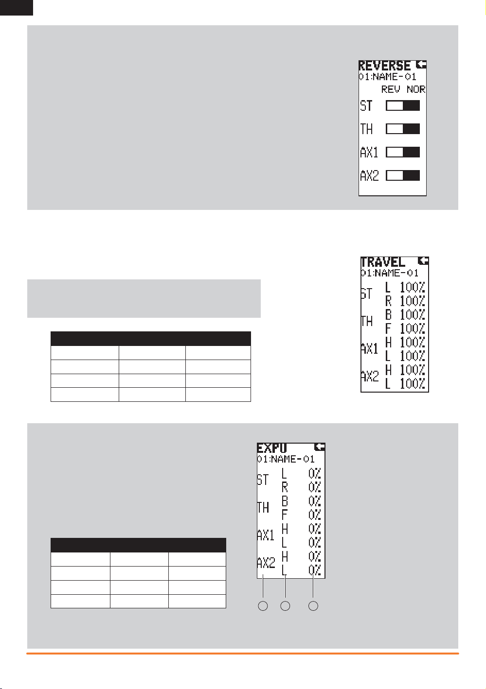
Reverse
The Reverse function, also known as servo reversing, establishes
the channel direction relative to the channel input. Use the reverse
menu if, for example, the wheels turn left when you turn the
steering wheel to the right. Reverse is available on all channels
and is normally the first function you should test and adjust during
programming.
Travel
The Travel function supports precise endpoint adjustments in all
channels. Travel values range from 0–150% (Default is 100%).
NOTICE: Always check the control directions at the extents of travel
to be sure the linkages do not bind. Travel values that are too high will
cause binding, which may result in damage to the vehicle.
Channel Top Bottom
Steering L (left) R (right)
Throttle B (brake) F (forward)
Aux 1 H (high) L (low)
Aux 2 H (high) L (low)
Exponential
The Exponential (Expo) function affects the response rate of
the steering, throttle and/or brake. A positive Steering Expo
value, for example, decreases steering sensitivity around
neutral to make it easier to drive at high speeds in a straight
line while still allowing for maximum turning radius. While
sensitivity with positive Expo is decreased around neutral, it
increases the sensitivity near the end of travel.
*Reference chart for options available on each channel:
Channel Top Bottom
Steering L (left) R (right)
Throttle B (brake) F (forward)
Aux 1 H (high) L (low)
Aux 2 H (high) L (low)
A Channel: Steering, Throttle or
Aux (auxiliary)
B Direction
C Adjustable value (from
-100% to +100% (0 is factory default or inhibit))
A B C
IMPORTANT: Both positive and negative Expo values are available. A positive Expo value results in the center being less
sensitive (desirable most of the time), while a negative value increases the sensitivity around center (normally not used).
8
Spektrum DX4S • tranSmitter inStruction manual
Page 9

RECEIVER COMPATIBILITY
The DX4S transmitter is compatible with Spektrum™ DSMR™, DSM®, DSM2®, and Marine surface receivers. The inlcuded
Spektrum SRS4210 DSMR Surface receiver is compatible with all Spektrum DSMR transmitters and is also backwards compatible
with DSM2 transmitters. The SR410 DSMR receiver is only compatible with DSMR transmitters.
AVC – Active Vehicle Control
AVC™ technology is the newest Spektrum™ RC innovation from Horizon Hobby. This Spektrum stabilization system adds a whole
new level of control to your RC driving experience. AVC technology utilizes sensors to adjust steering and throttle output, providing
you with a more stable and controlled driving experience.
NOTICE: You must use digital servos with the SRS4210 receiver. Using analog servos will reduce the performance of the system and
may cause analog servos to overheat.
SR410 Receiver Installation
Install the receiver in your vehicle using double-sided foam
servo tape. Foam servo tape holds the receiver in place and
protects the receiver from vibration. Position the antenna
vertically and away from the vehicle in an antenna tube. The
SR410 and SRS4210 have a coax style antenna. The last 31mm
of the antenna is the portion that receives the signal from the
transmitter.
EN
SRS4210 Receiver Connection and Installation
You must install the SRS4210 receiver in the vehicle before
binding the transmitter and receiver. The receiver can be
mounted flat with the label up or on its side. When you bind the
receiver, the AVC system automatically detects the orientation
of the receiver. The receiver must be mounted completely flat
when in the label-up orientation or completely perpendicular
when mounted on its side. If the receiver is angled even slightly,
AVC may not function properly. If the orientation of the receiver
is changed after binding, you must then rebind for AVC to fuction
properly.
Install the Receiver in your vehicle using the included doublesided foam servo tape. Foam servo tape will hold the receiver in
place and help isolate it from vibrations.
NOTICE: Do not cut or modify the antenna.
IMPORTANT: Do not use hook & loop material to install the
SRS4210 receiver. Using hook & loop material will affect the
performance of the AVC system.
Mount the antenna up and away from the vehicle in an antenna
tube. The higher up the antenna is, the better signal it will
receive.
Aux channels
The Aux channels can operate as additional servo channels, or as a power supply for a personal transponder. If AVC is active, only two
channels, Steering and Throttle, are operational. The Aux channels can be used to power a personal transponder or lights.
If AVC is disabled (see DISABLING THE STABILITY ASSIST FUNCTION to disable AVC), the Aux channels will operate as servo channels.
Antenna
Aux 2 Port
Aux 1 Port
Throttle Port
Steering Port
Bind/
Battery Port
Bind/Battery Port
Disable
Data
Aux 2 Port
Aux 1 Port
Throttle Port
Steering Port
Antenna
Spektrum DX4S • tranSmitter inStruction manual
9
Page 10

EN
Electric Vehicle Installation
Typical Nitro Vehicle Installation
BatteryTo Motor
Electronic
Speed Control
Receiver
Steering Servo
Battery
Receiver
Throttle Servo
Steering Servo
IMPORTANT: If you adjust the steering and throttle trim on your transmitter, the receiver must be turned off and back on again in
order to save the new trim settings. Otherwise, AVC will not function properly.
Failsafe
The throttle failsafe position is set during binding. In the unlikely event that the radio link is lost
during use, the receiver will drive the the throttle servo to its pre-programmed failsafe position
(normally full brakes) and all other channels will have no servo output. If the receiver is turned on
prior to turning on the transmitter, the receiver will enter the failsafe mode, driving the throttle servo
to its preset failsafe position. When the transmitter is turned on, normal control is resumed.
IMPORTANT: Failsafe activates only in the event that the signal is lost from the transmitter. Failsafe
will NOT activate in the event that receiver battery power decreases below the recommended
minimums or power to the receiver is lost.
The Bind Screen shows the active model and supports binding the active model memory to a
receiver.
Bind
Binding is the process of teaching the receiver the specific transmitter’s code called GUID (Globally Unique Identifier) and storing
failsafe values. When a receiver is bound to a transmitter/model memory, the receiver will only respond to that specific transmitter/
model memory (see ModelMatch for more information).
10
Spektrum DX4S • tranSmitter inStruction manual
Page 11

Bind Transmitter to SR410 Receiver
1. Insert a bind plug in the receiver’s BIND port.
2. Power on the receiver and wait until the receiver LED begins flashing.
3. Power on the transmitter.
4. Select the Model Memory you wish to bind to.
5. Select Bind from the List menu.
6. Move the throttle channel to the desired failsafe position.
IMPORTANT: The throttle channel must stay in the failsafe position until binding is complete.
7. Scroll to Bind and press the Rolling Selector. The orange LED flashes on top of the transmitter.
8. When the bind process is complete, the transmitter and receiver LEDs stop flashing and turn solid orange.
NOTICE: Always remove the bind plug from the receiver when the bind process is complete. Failure to do so will cause the receiver to
enter bind mode the next time you power on the receiver.
Binding and Calibrating the SRS4210 Receiver
You must calibrate the receiver each time it is placed in bind mode.
IMPORTANT: The following sequence of steps must be followed in order for AVC to function properly.
1. Insert the Bind Plug in the BIND port on the receiver.
2. Power on the receiver. The orange LED flashes, indicating the receiver is in bind mode.
3. Center the ST TRIM and TH TRIM on the transmitter.
4. Put your transmitter in bind mode.
5. The bind process is complete when the orange LED on the receiver is solid.
6. Pull the transmitter trigger to Full Throttle.
7. Push the transmitter trigger to Full Brake, then return the trigger to center.
8. Turn the transmitter steering wheel to Full Right.
9. Turn the transmitter steering wheel to Full Left, then return the steering wheel to center. The orange LED flashes once.
10. Remove the bind plug once the calibration and binding process is complete.
11. Power off the transmitter.
IMPORTANT: You must rebind the transmitter and receiver if you:
•
Change the servo reverse after binding
•
Change the travel after binding
•
Want to use the receiver with a different model memory
If you change the servo reversing or travel adjust after binding, AVC will not work properly.
EN
Disabling the Stability Assist Function
If you participate in organized racing, you may be required to turn AVC technology off. To turn off AVC technology, insert a second
Bind Plug in the Disable port before binding.
IMPORTANT: You must calibrate the receiver each time it is placed in bind mode. To activate AVC, see the steps in BINDING AND
CALIBRATING THE RECEIVER.
Sub-Trim
The Sub-Trim function enables you to correct minor servo arm offsets by electronically
adjusting the center point of the servo. Sub-trim is available on all channels.
CAUTION: Only use small sub-trim values so you do not exceed the maximum
servo travel. If you find the servo requires a large amount of sub-trim, return the
sub-trim to 0 and adjust the servo arm on the servo spline manually.
*Reference chart for options available for each channel:
Channel Description
Steering L (left) R (right)
Throttle B (brake) F (forward)
Aux 1 H (high) L (low)
Aux 2 H (high) L (low)
Spektrum DX4S • tranSmitter inStruction manual
11
Page 12
EN
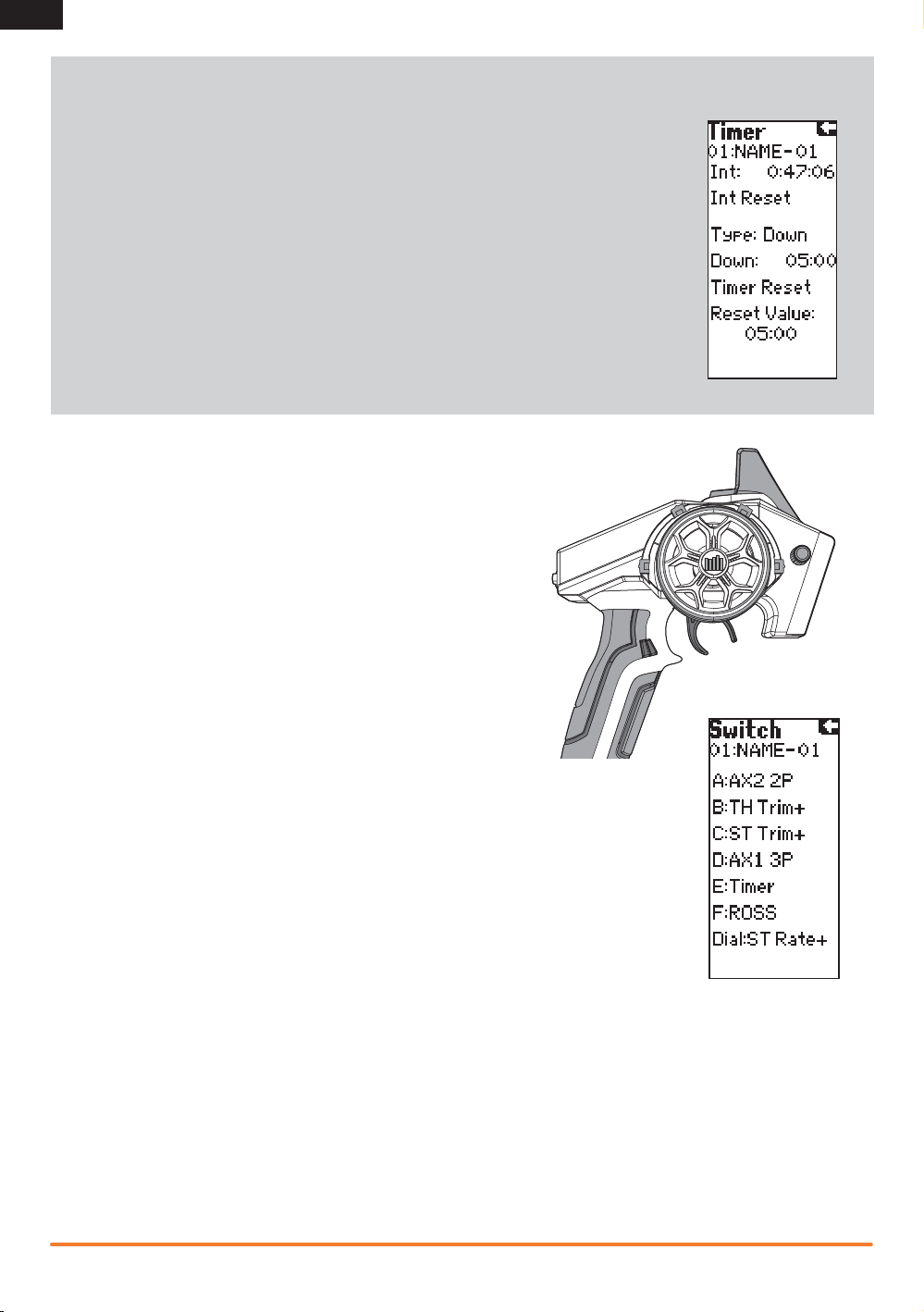
Timer
The transmitter Timer can function as either an Up or Down Timer.
Down Timer (default selection)
The Down Timer allows you to adjust the amount of time in 10 second increments to a
maximum of 21 minutes, which will then start a countdown to “0” once activated. The Down
Timer value is normally the length of a race or vehicle run time. The Down Timer can be reset
by selecting Timer Reset or by holding the switch that is assigned to that timer for 3 seconds.
Up Timer
The Up Timer functions as a stopwatch and is useful for determining the available run time in
one tank of fuel or a battery pack.
Using the Timer
1. Assign the timer to a switch or button in the Switch menu.
2. To start or stop the timer, hold the assigned button.
3. To reset the timer, press the timer button for more than 3 seconds.
Switch
The Switch menu enables you to assign any of the seven switches to one of
the following functions. Switches that have a +/- next to the name can be
assigned to different directions. For example, ST trim+ causes right steering
trim to trim the steering to the right. ST trim- trims the steering to the left.
Aux1 and Aux2 can only be assigned to one function at a time. For example,
if Aux1 is assigned to 4WS Mix, then it it will not be available as an option on
the switch screen.
Switch A, B, C, D and E
Inhibit – Switch off
AX1 Lin – Ch 3 Linear
AX1 2P – Ch 3 2-position
AX1 3P – Ch 3 3-position
AX1 MT – Ch 3 Momentary
AX2 Lin – Ch 4 Linear
AX2 2P – Ch 4 2-Position
AX2 3P – Ch 4 3-Position
AX2 MT – Ch 4 Momentary
ST Trim+ – Steering Trim
ST Trim- – Steering Trim
TH Trim+ – Throttle Trim
TH Trim- – Throttle Trim
AX1 Trim+ – Ch 3 Trim
Switch F
Inhibit
AX1 2P
AX1 MT
AX2 2P
AX2 MT
ROSS
Timer
4WS Mix
Mix A
Mix B
Dial
AX1 Trim- – Ch 3 Trim
AX2 Trim+ – Ch 4 Trim
AX2 Trim- – Ch 4 Trim
Brake+ – Full Brake Trim
Brake- – Full Brake Trim
ST Rate+ – Steering Rate
ST Rate- – Steering Rate
ROSS – Remote Start
Timer – Up or Down Timer
4WS Mix – 4 Wheel Steer
BAK Mix – Brake Mix
Mix A – Mix A Function
Mix B – Mix B Function
Mix A Rate – Mix A Value
Mix B Rate – Mix B Value
AX1 Lin
AX2 Lin
ST Trim+
ST TrimTH Trim+
TH TrimAX1 Trim+
AX1 TrimAX2 Trim+
AX2 Trim-
Brake+
BrakeST Rate+
St Rate-
12
Spektrum DX4S • tranSmitter inStruction manual
Page 13

Mixing
The DX4S features a Steer Mix, Brake Mix and two programmable mixes (Mix A and Mix B).
Steer Mix
Use the Steer Mix for vehicles requiring either four-wheel steering (4WS) or dual steering servos
(Dual ST).
NOTICE: Before driving a model, always do a check of the transmitter’s control of the vehicle with
the vehicle’s wheels off the ground.
Mix Options
1. Select AX1 or AX2 as the slave channel. Aux1 and Aux2 can only be assigned to one mix at a
time. If Aux1 or Aux 2 is assigned to another mix, it will not be available as a slave
channel option.
2. Adjust the A Value. The value shown is the percentage of slave channel input compared to
master channel input.
For example, 100% means the slave channel movement is equal to the master channel
movement. If you adjust the value to 50%, the slave channel moves half as far as the master
channel. A negative value means the mix moves in the opposite direction.
4-Wheel Steer Mix
Mix options:
• 4-Wheel Steer
• Front Steer
• Crab Steering
• Rear Steer
EN
1. Scroll to Mixing, then select Steer Mix.
2. Select 4WS.
3. Select Inh, then scroll to activate the 4WS mix on Aux 1
or Aux 2.
4. To inhibit a Mix Option, scroll to the steering option, then select Inh. When a steering option
is inhibited, the switch ignores the option. All steering options are active by default.
5. Adjust the steering rate for the 4-Wheel Steering options (4WS and Crab)
The values shown in the 4WS screen are the rear steering rate values.
For example, “100/100” means the rear steering rate is 100% of the front steering value.
“50/50” means the rear steering rate is 50% of the front steering value in both the left and
right directions.
6. Activate/Deactivate Trim (4-Wheel Steering Only)
When Trim is active, the steering trim switch adjusts both the front and rear steering trim. If Trim
is inhibited, the steering trim button only affects the front steering.
7. Switch: Assign the 4-Wheel Steering Options to a switch. Each time you move the switch,
the 4-Wheel Steering options appear on the Main Screen.
Spektrum DX4S • tranSmitter inStruction manual
13
Page 14

EN
Dual ST (Dual Steering)
Trim: Act (Default) or Inh. We recommend activating the Trim, as it adjusts the trim for both the left and right steering servos. If you
need to make small adjustments to the individual servos, you can do so in the Sub-Trim menu.
Switch: You may assign the Dual ST mix to a switch, enabling a B Value in the mix. Assigning the Dual ST mix to a switch is valuable
when you want to assign dual steer values for different conditions. For example, you may use a smaller value when the vehicle is moving
faster. When the vehicle is moving slowly, use the switch to select the larger value and increase steering ability. You can also set one of
the mix values to 0% if you want to turn the mix off.
Brake Mix
Use the Brake Mix on large scale vehicles that require separate front and rear brake servos. The
mix value creates brake bias between the front and rear brakes. Assigning the Brake Mix to a switch
enables you to adjust the mix value from any screen.
1. Select AX1 or AX2 as the Slave channel. If Aux 1 or Aux 2 is assigned to another mix, it will not be
available as a Slave channel option.
2. Adjust the Brake Mix Value to establish the brake bias between the front and rear brakes. Switch:
You may assign the Brake Mix to a switch. Assigning the Brake Mix to a switch enables you to
adjust the brake bias from any screen.
Motor On Axle (MOA) Throttle Mix
The MOA Throttle Mix is used to adjust the throttle bias on rock crawlers using a “motor on axle” configuration.
Mix options:
• Rear Dig
• Front Dig
• 4WD
1. Select MOA from the Throttle Mix menu.
2. Scroll to Inh. Press the scroll wheel, then scroll to activate the mix. Press the
scroll wheel again to adjust the mix.
3. To inhibit an option
Scroll to the MOA option, then select Inh. All MOA options are active by
default. If you inhibit an option, the Mix switch ignores the option.
4. Adjust the Throttle Bias Value (4WD Only)
The value shown on the screen is a percentage of the rear motor rate.
For example, a value of “70%” means the rear motor power is 70% of the
front motor power.
5. In Motion Adjustment
You can assign the throttle bias to the following switches:
• A
• B
Assigning the Throttle Bias to a switch enables you to adjust the throttle bias
while the vehicle is moving.
6. Assigning the Mix Options to a Switch
Assign the MOA Options to a switch. Each time you move the Mix switch, the
MOA options appear on the Main Screen.
Bias Step:
The Bias Step affects the amount the mix changes with each click of the button or
dial but has no effect on the total mix range.
• C
• D
• E
• Dial
Main Screen MOA Mix Screen
14
Spektrum DX4S • tranSmitter inStruction manual
Page 15

Active Vehicle Control (AVC)
Options:
• ST Gain
• TH Gain
• Priority
1. Select AVC from the LIST menu.
2. Change the State field to ACT .
3. Adjust the ST Gain and/or TH Gain Sensitivity
The default value is 0% (ST Gain and TH Gain OFF). As
the value increases, the AVC steering stability and throttle
management increases.
Adjust the ST Gain until you reach the ideal amount of
steering control. If the front wheels begin to shake, the ST
Gain value is too high. Reduce the ST Gain value until the
front wheels stop shaking. You can assign ST Gain and TH
Gain to the same switch, enabling you to adjust both values
at the same time.
4. Switch: Assigning ST Gain and TH Gain to a switch enables
you to adjust the sensitivity without using the AVC menu. ST
GAIN and TH GAIN can be assigned to the same switch to
adjust both simultaneously.
5. Adjust the Steering Priority
The Priority default value is 0%, meaning AVC is active when
the steering is close to center. As you turn the steering wheel
away from center (neutral), the transmitter controls have
priority over the AVC system. Increasing the Priority value
decreases how active AVC is as the steering wheel is turned
left and right. For example, if you increase Priority to 80%,
you reduce the AVC steering control by 80% at full left or full
right steering. Increasing the Steering Priority enables you to
make tighter turns.
EN
List Menu
ST Gain when active
drives the Aux 1
TH Gain when active
drives the Aux 2
Priority adjusts ST Gain
based on the steering
input.
AVC Screen
Spektrum DX4S • tranSmitter inStruction manual
15
Page 16

EN
Programmable Mix
The programmable mixes enable you to assign any
channel as a Master or Slave, which is particularly
helpful when you need to assign an Aux channel as
a Master.
1. Scroll to Inh. Press the rolling selector once
and select a Master channel.
2. Select a Slave channel.
3. Adjust the A Value percentage.
You can assign custom names to Mix A and Mix B,
making it easier to remember what each mix does.
Assign the names the same way you would for the
Username or Model Name.
Mix Options
Trim: Inh or Act. When Trim is Active, trim adjustments to the Master channel also apply to the
Slave channel.
Servo Speed
The Servo Speed function allows you
to change the speed of any of the four
channels—steering, throttle and Aux. from
100% (default) to 1%. The maximum speed
is 100% and is fixed by the specifications
of the servo itself.
• In the List screen, use the roller to
highlight the Servo Speed function.
Press the roller to access the Servo
Speed function. The Servo Speed screen
appears.
• Use the roller to select the desired
channel, then press the roller to access
that channel. Rotate the roller to adjust the servo speed.
Switch: You may assign the mix to a switch,
enabling a B Value in the mix.
To adjust the B Value:
1. Assign a switch to the mix.
2. Press the switch forward or back. The A Value
changes to B Value on the screen.
3. Select the B Value and move the scroll wheel to
adjust the value.
4. Press the Rolling Selector to save the selection.
NOTICE: Before driving a model, always do a
check of the model’s response to mix settings.
Raise the vehicle off the ground so it does not
move during testing.
IMPORTANT: A negative value results in the
secondary channel moving in a direction opposite the direction of the primary channel.
Trim Step
Trim Step affects the amount the
servo travels with each click of
the trim, but has no effect on the
total trim travel. The trim steps
range from 1 to 20 (Default is 4).
To adjust the trim step:
1. Select Trim Step from the List
menu.
2. Scroll to the desired channel
and press the scroll wheel to
activate the channel.
3. Rotate the scroll wheel to
adjust the trim step.
4. Press the scroll wheel to save
the selection.
ABS (Automatic Breaking System or Pulse Brakes)
ABS helps prevent brake lock-ups and improves braking
performance by pulsing the brakes.
The following ABS braking parameters can be programmed:
State: Inhibit or Active
Point: The throttle position that the pulse braking
takes place. (0 to 100, default is 60)
Stroke: The distance the throttle travels during the
pulse braking. (0 to 100, default is 50)
Lag: The time delay before the pulsing takes place
(0.0 to 2.0 in .01 increments, default is 0.5)
Speed: The pulsing speed or frequency of the pulse
braking. (-1 to -30, default is -1)
The graphic bar at the bottom of the screen displays the parameters
and shows how ABS will function.
16
IMPORTANT: State must be Active to
turn on the ABS function.
• In the List screen, use the roller to
highlight the ABS function.
• Press the roller to access the ABS
function. The ABS screen appears.
• Use the roller to select the ABS
parameter you wish to adjust.
• Press the roller to highlight that
parameter and the associated box
will flash. Rotate the roller to adjust
that function.
Spektrum DX4S • tranSmitter inStruction manual
Page 17

Throttle Punch
The Throttle Punch function is used to offset the throttle to a preprogrammed position and activate
when 4% of throttle travel is applied. Throttle punch is typically used in nitro vehicles to reduce the lag
due to throttle linkage slack.
To Access the Throttle Punch Function:
• In the List screen, use the Rolling Selector to highlight the Th Punch function.
• Press the Rolling Selector to access the Throttle Punch function. The above screen will appear.
• Use the Rolling Selector and place a box around Th Punch. Press the Rolling Selector and the
surrounding box will flash, then rotate the Rolling Selector to adjust the value of the throttle punch
position. Press the Rolling Selector.
IMPORTANT: Throttle punch will remain active until the value is reset to zero.
To return to the main screen, press and hold the Rolling Selector for more than
three seconds.
Reset
The Model Reset function restores factory default settings for
the active model memory.
• Choosing Yes affirms erasing saved settings for the active
model memory and return of factory defaults. A box shows
around selected text.
• Choosing No returns to the List Screen.
EN
IMPORTANT: Model information saved in a memory is
erased when that model memory is copied over or reset to
factory default settings.
Monitor
The servo monitor displays the servo output positions graphically and digitally. This
monitor can be useful in troubleshooting setups, displaying mixing functions and how
they interrelate.
• In the List screen, use the roller to highlight
the Monitor function.
• Press the roller to access the Monitor function.
The real-time servo output positions will display.
Spektrum DX4S • tranSmitter inStruction manual
17
Page 18

EN
System
The System function lets you adjust transmitter functions.
List
Two modes are available: Expert and Standard. The DX4S
defaults to Expert where all of the programming menus are
available. Standard mode eliminates the expert screens and
functions from the list, making it ideal for basic models.
Display
Contrast
The contrast function provides adjustment to the brightness
ratio of the lightest to the darkest part of the screen. You can
set the contrast to a value from 0 to 30 (0 is lightest and 30 is
darkest).
Light
You can set the backlight to one of three modes: Timer, On or
Off.
• Timer: The backlight will turn off after a preset delay.
• On: The backlight never turns off when the transmitter is on.
• Off: The backlight is always off.
1. Use the Rolling Selector to access Light.
2. Press the roller and the surrounding box will flash.
3. Rotate the roller to the desired backlight mode and press
the roller to select it.
Lang (Language)
The DX4S can display the screen text in one of four
languages: English (default), German, French, and Italian.
Use the roller and select the Language function.
Alert
You can set an alarm to sound when the battery voltage gets to
the limit set with the Alert. Battery voltage is displayed on the
Main Screen.
Menu: None, Tone, Vibe, Both
Sets the alert type for scrolling through the menu items and
selecting items.
Tone: You can adjust the buzzer to either Low or High
IMPORTANT: Buzzer adjustment does not change the
sound level for Inactivity or Low Battery warnings.
Tx Battery Voltage: Set an alarm to sound when the
battery voltage reaches the limit.
Battery voltage options are Alkaline, Ni-MH or Li-Po. After you
select the battery type, you can raise the voltage limit.
Tx Battery Alert Type: None, Tone
Timer: None, Tone, Vibe, Both
Sets the alert type for the down timer.
All of the alert settings above affect all models.
Telemetry: Rx Battery Alert Type:
None, Tone, Vibe, Both. Sets
the alert type for the telemetry
receiver battery voltage.
Temp Alert Type: None, Tone, Vibe,
Both. Sets the alert type for the
telemetry temperature.
The telemetry alert settings are
model specific.
F Rate (Frame Rate)
Frame rate is the response rate of the
receiver. The lower the number, the
faster the response. Frame rate only
affects the current model.
IMPORTANT: You should always use the fastest response
rate the servos can handle. This gives the lowest latency and
fastest response. If the frame rate is incompatible with the
servo, the servo will move erratically or in some cases not at
all. If this occurs, change the frame rate to the next highest
value.
The available frame rates will depend on the type of receiver the
DX4S is bound to:
DSMR: 11 or 22ms DSM: 11 or 16.5ms
DSM2: 11 or 16.5ms Marine: 22ms
1. Use the roller to highlight the F Rate function.
2. Press the roller.
3. Rotate the roller to select the frame rate and press the roller
to save the selection.
RS Port
This sets the port – (Bind or Aux (Auxiliary) – on the receiver for
ROSS (Remote Onboard Starting System) connection. RS Port is
model specific.
Username
You can program a user name with up to 8 characters. This
name is displayed on the Main Screen. In the System screen,
highlight the User Name and press the roller to access the
function. Use the roller to select the position, then press the
roller to access a character. Username affects all models.
About
This screen displays the transmitter serial number (which is
required when downloading firmware updates) and the release
level of the transmitter’s software. Refer to Memory Card
instructions for updating transmitter firmware.
18
Spektrum DX4S • tranSmitter inStruction manual
Page 19

Telemetry
The Telemetry setting function is used to select a default screen for display, including Main, Telemetry or
Roll. It is also used to access the Telemetry SPEED, BATTERY and TEMPERATURE sensor settings.
To Access the Telemetry Setting function:
In the List screen, use the Rolling Selector to highlight Telemetry, then press the Rolling Selector. The
TELEMETRY screen will appear. To select the default screen, rotate the Rolling Selector to place the box
around Screen TELE, then press the Rolling Selector. The surrounding box will flash.
• TELE displays the Telemetry screen.
• MAIN (default) aways hides the Telemetry Screen.
• ROLL allows the roller to select between the Telemetry and Main screens.
Rotate the Rolling Selector and choose your desired default screen (TELE displays the Telemetry screen.
ROLL will allow the Rolling Selector to select between the Telemetry and Main Screens). Press the Rolling
Selector to select.
1. Use the Rolling Selector to select the sensor parameters to adjust.
2. Press the Rolling Selector and a surrounding box will flash.
3. Use the Rolling Selector to adjust the value, then press the Rolling Selector to select.
4. To return to the main screen, press and hold the Rolling Selector for more than three seconds.
Rx Battery: The Battery Alert setting allows you to preset a low voltage warning. When the battery voltage in your receiver drops
below the preset voltage, the transmitter will alert you.
Temp Unit: Display Temperature Unit in degree Fahrenheit or Celsius.
Upper: The Upper value is the maximum range of the temperature scale.
Alert: The alert warning activates when the temperature sensor recognizes the set value, for example, when a nitro engine reaches
280 degrees Fahrenheit.
Lower: The Lower value is the minimum range of the temperature scale
The Telemetry screen displays the maximum achieved temperature from the point that the receiver was turned on. To reset the maxi-
mum recorded temperature, it is necessary to power OFF the receiver, then power it ON.
EN
Sp. Unit: Select RPM, MPH or KM/H display units.
Zoom: The Zoom setting sets the maximum range or boundary of the Speed unit.
Roll Out: Roll out appears when you assign the MPH or KM/H Speed Unit. A Roll Out value (conversion factor) is required to
display the value in MPH or KM/H. When the Roll Out value is 1.0’ (default), the value displayed on the main screen and stored in
maximum speed is the rpm of the spur gear or flywheel triggering the RPM Sensor. To calculate the Roll Out value, use one of the
following methods:
Method A (Nitro or Gas Vehicles):
1. Put a small reference mark on the flywheel. A black or silver permanent marker works well.
2. Put the car next to a ruler and align the front of the car with the 0 mark. Use your hand to roll the car forward while counting each
revolution of the reference mark. At exactly 10 revolutions, stop the car.
3. Measure the exact total distance that the car traveled and divide this distance by 10. For example, 12.0” divided by 10 = 1.20”.
4. Adjust the Roll Out value on the transmitter until 1.20 appears on the screen. Now all rpm-related functions will appear in mph or
km/h.
Method B (Electric Vehicles): For this method you either need to know the internal gear ratio (normally provided in the vehicle’s
manual) or be able to calculate the ratio via the number of teeth on the gears. It is also necessary to calculate the circumference
of the tire. Once the internal ratio is known, and the circumference in inches has been determined, simply divide the circumference by the internal ratio and use this value as the conversion.
To calculate the circumference—multiply 3.14 by the tire diameter (in inches).
To calculate the internal gear ratio—divide the larger transmission gear by the smaller gear. With multiple gear transmissions it is
necessary to multiply each of the larger to smaller gear reduction ratios to arrive at the final ratio.
The Telemetry screen displays the maximum recorded speed from the point that the receiver was turned on. To reset the maxi-
mum recorded speed, it is necessary to power OFF the receiver, then power it ON.
Spektrum DX4S • tranSmitter inStruction manual
19
Page 20

EN
TROUBLESHOOTING GUIDE
Problem Possible Cause Solution
The system will
not connect
The receiver goes
into failsafe mode a
short distance away
from the transmitter
Receiver quits
responding during
operation
Receiver loses its
bind
Receiver taking
longer than usual to
link with transmitter
The front wheels
oscillate
The front wheels turn
the wrong way when
the car slides/rotates
The throttle does not
reduce when the car
slides/rotates
Transmitter and receiver too near each other Move transmitter 8 to 12 feet (2.4 to 3.6m) from
Transmitter and receiver too near large metal
objects (vehicles, etc.)
Selected model is not bound in transmitter Make sure correct model memory is selected and that
Transmitter accidentally put in bind mode so
receiver is no longer bound
Check the receiver antenna to be sure it is not
cut or damaged
Low battery voltage Completely recharge battery
Loose or damaged wires or connectors between
battery and receiver
Transmitter accidentally put in bind mode, ending
bind to receiver
Transmitter and receiver are operating on Marine
model
The steering gain
is set too high
The steering channel was reversed after
calibration
The throttle channel was reversed after calibration Rebind and calibrate
receiver
Move away from large metal objects (vehicles, etc.)
transmitter is bound to the model
Rebind transmitter and receiver
Replace or contact Horizon Product Support
Make sure receiver antenna is in an antenna tube and
is above vehicle
Do a check of the wires and connection between
battery and receiver. Repair or replace wires and/or
connectors
Bind transmitter to receiver
Marine receivers can take longer to link with
transmitter
Turn down the steering gain
Rebind and calibrate
20
Spektrum DX4S • tranSmitter inStruction manual
Page 21

1-YEAR LIMITED WARRANTY
EN
What this Warranty Covers
Horizon Hobby, Inc., (Horizon) warrants to the original purchaser
that the product purchased (the “Product”) will be free from
defects in materials and workmanship for a period of 1 years
from the date of purchase.
What is Not Covered
This warranty is not transferable and does not cover (i) cosmetic
damage, (ii) damage due to acts of God, accident, misuse, abuse,
negligence, commercial use, or due to improper use, installation,
operation or maintenance, (iii) modification of or to any part of the
Product, (iv) attempted service by anyone other than a Horizon
Hobby authorized service center, (v) Product not purchased from
an authorized Horizon dealer, or (vi) Product not compliant with
applicable technical regulations.
OTHER THAN THE EXPRESS WARRANTY ABOVE, HORIZON
MAKES NO OTHER WARRANTY OR REPRESENTATION, AND
HEREBY DISCLAIMS ANY AND ALL IMPLIED WARRANTIES,
INCLUDING, WITHOUT LIMITATION, THE IMPLIED WARRANTIES
OF NON-INFRINGEMENT, MERCHANTABILITY AND FITNESS FOR
A PARTICULAR PURPOSE. THE PURCHASER ACKNOWLEDGES
THAT THEY ALONE HAVE DETERMINED THAT THE PRODUCT
WILL SUITABLY MEET THE REQUIREMENTS OF THE
PURCHASER’S INTENDED USE.
Purchaser’s Remedy
Horizon’s sole obligation and purchaser’s sole and exclusive
remedy shall be that Horizon will, at its option, either (i) service,
or (ii) replace, any Product determined by Horizon to be defective.
Horizon reserves the right to inspect any and all Product(s)
involved in a warranty claim. Service or replacement decisions
are at the sole discretion of Horizon. Proof of purchase is
required for all warranty claims. SERVICE OR REPLACEMENT AS
PROVIDED UNDER THIS WARRANTY IS THE PURCHASER’S SOLE
AND EXCLUSIVE REMEDY.
Limitation of Liability
HORIZON SHALL NOT BE LIABLE FOR SPECIAL, INDIRECT,
INCIDENTAL OR CONSEQUENTIAL DAMAGES, LOSS OF
PROFITS OR PRODUCTION OR COMMERCIAL LOSS IN ANY
WAY, REGARDLESS OF WHETHER SUCH CLAIM IS BASED IN
CONTRACT, WARRANTY, TORT, NEGLIGENCE, STRICT LIABILITY
OR ANY OTHER THEORY OF LIABILITY, EVEN IF HORIZON HAS
BEEN ADVISED OF THE POSSIBILITY OF SUCH DAMAGES.
Further, in no event shall the liability of Horizon exceed the
individual price of the Product on which liability is asserted.
As Horizon has no control over use, setup, final assembly,
modification or misuse, no liability shall be assumed nor
accepted for any resulting damage or injury. By the act of use,
setup or assembly, the user accepts all resulting liability. If you
as the purchaser or user are not prepared to accept the liability
associated with the use of the Product, purchaser is advised to
return the Product immediately in new and unused condition to
the place of purchase.
Law
These terms are governed by Illinois law (without regard to
conflict of law principals). This warranty gives you specific legal
rights, and you may also have other rights which vary from state
to state. Horizon reserves the right to change or modify this
warranty at any time without notice.
WARRANTY SERVICES
Questions, Assistance, and Services
Your local hobby store and/or place of purchase cannot provide
warranty support or service. Once assembly, setup or use of the
Product has been started, you must contact your local distributor
or Horizon directly. This will enable Horizon to better answer your
questions and service you in the event that you may need any
assistance. For questions or assistance, please visit our website
at www.horizonhobby.com, submit a Product Support Inquiry, or
call the toll free telephone number referenced in the Warranty
and Service Contact Information section to speak with a Product
Support representative.
Inspection or Services
If this Product needs to be inspected or serviced and is compliant
in the country you live and use the Product in, please use the
Horizon Online Service Request submission process found on
our website or call Horizon to obtain a Return Merchandise
Authorization (RMA) number. Pack the Product securely using a
shipping carton. Please note that original boxes may be included,
but are not designed to withstand the rigors of shipping without
additional protection. Ship via a carrier that provides tracking
and insurance for lost or damaged parcels, as Horizon is not
responsible for merchandise until it arrives and is accepted at
our facility. An Online Service Request is available at http://www.
horizonhobby.com/content/_service-center_render-servicecenter. If you do not have internet access, please contact Horizon
Product Support to obtain a RMA number along with instructions
for submitting your product for service. When calling Horizon,
you will be asked to provide your complete name, street address,
email address and phone number where you can be reached
during business hours. When sending product into Horizon,
please include your RMA number, a list of the included items,
and a brief summary of the problem. A copy of your original sales
receipt must be included for warranty consideration. Be sure
your name, address, and RMA number are clearly written on the
outside of the shipping carton.
NOTICE: Do not ship LiPo batteries to Horizon. If you
have any issue with a LiPo battery, please contact the
appropriate Horizon Product Support office.
Warranty Requirements
For Warranty consideration, you must include your original sales
receipt verifying the proof-of-purchase date. Provided warranty
conditions have been met, your Product will be serviced or
replaced free of charge. Service or replacement decisions are at
the sole discretion of Horizon.
Non-Warranty Service
Should your service not be covered by warranty, service
will be completed and payment will be required without
notification or estimate of the expense unless the
expense exceeds 50% of the retail purchase cost. By
submitting the item for service you are agreeing to payment of
the service without notification. Service estimates are available
upon request. You must include this request with your item
submitted for service. Non-warranty service estimates will be
billed a minimum of ½ hour of labor. In addition you will be billed
for return freight. Horizon accepts money orders and cashier’s
checks, as well as Visa, MasterCard, American Express, and
Discover cards. By submitting any item to Horizon for service,
you are agreeing to Horizon’s Terms and Conditions found on
our website http://www.horizonhobby.com/content/_servicecenter_render-service-center.
ATTENTION: Horizon service is limited to Product
compliant in the country of use and ownership. If
received, a non-compliant Product will not be serviced.
Further, the sender will be responsible for arranging
return shipment of the un-serviced Product, through
a carrier of the sender’s choice and at the sender’s
expense. Horizon will hold non-compliant Product for a
period of 60 days from notification, after which it will be
discarded.
Spektrum DX4S • tranSmitter inStruction manual
21
Page 22

EN
WARRANTY AND SERVICE CONTACT INFORMATION
Country of
Purchase
United States of America
United Kingdom
Germany
France
China
Horizon Hobby Contact Information Address
Horizon Service Center
(Repairs and Repair Requests)
Horizon Product Support
(Product Technical Assistance)
Sales
Service/Parts/Sales:
Horizon Hobby Limited
Horizon Technischer Service service@horizonhobby.de
Sales: Horizon Hobby GmbH +49 (0) 4121 2655 100
Service/Parts/Sales:
Horizon Hobby SAS
Service/Parts/Sales:
Horizon Hobby – China
servicecenter.horizonhobby.com/
infofrance@horizonhobby.com
FCC INFORMATION
This device complies with part 15 of the FCC rules. Operation
is subject to the following two conditions: (1) This device may
not cause harmful interference, and (2) this device must accept
any interference received, including interference that may cause
undesired operation.
CAUTION: Changes or modifications not expressly
approved by the party responsible for compliance could
void the user’s authority to operate the equipment.
This product contains a radio transmitter with wireless technology which has been tested and found to be compliant with
the applicable regulations governing a radio transmitter in the
2.400GHz to 2.4835GHz frequency range.
RequestForm/
www.quickbase.com/db/
bghj7ey8c?a=
GenNewRecord
888-959-2306
sales@horizonhobby.com
888-959-2306
sales@horizonhobby.co.uk
+44 (0) 1279 641 097
+33 (0) 1 60 18 34 90
info@horizonhobby.com.cn
+86 (021) 5180 9868
Harlow, Essex, CM18 7NS, United Kingdom
4105 Fieldstone Rd
Champaign, Illinois, 61822 USA
Units 1–4 , Ployters Rd, Staple Tye
Christian-Junge-Straße 1
25337 Elmshorn, Germany
11 Rue Georges Charpak
77127 Lieusaint, France
Room 506, No. 97 Changshou Rd.
Shanghai, China 200060
Antenna Separation Distance
When operating your Spektrum transmitter, please be sure to
maintain a separation distance of at least 5 cm between your
body (excluding fingers, hands, wrists, ankles and feet) and the
antenna to meet RF exposure safety requirements as determined
by FCC regulations.
The illustrations below show the approximate 5 cm RF exposure
area and typical hand placement when operating your Spektrum
transmitter.
IC INFORMATION
This device complies with Industry Canada licence-exempt RSS standard(s). Operation is subject to the following two conditions:
(1) this device may not cause interference, and (2) this device must accept any interference, including interference that may cause
undesired operation of the device.
22
Spektrum DX4S • tranSmitter inStruction manual
Page 23

COMPLIANCE INFORMATION FOR THE EUROPEAN UNION
EN
AT BE BG CZ CY DE DK
EE ES FI FR GR HR HU
IE IT LT LU LV MT NL
PL PT RO SE SI SK UK
IS LI NO CH
Declaration of Conformity
(in accordance with ISO/IEC 17050-1)
No. HH2012111801
Product(s): DX4S 4-Channel DSMR Sport System
Item Number(s): SPM4010
Equipment class: 2
The object of declaration described above is in conformity with the
requirements of the specifications listed below, following the provisions
of the European R&TTE directive 1999/5/EC:
EN 300-328 V1.7.1: 2006
EN 301 489-1 V1.7.1: 2006
EN 301 489-17 V1.3.2: 2008
EN60950-1:2006+A11:2009+A1:2010+A12: 2011
Signed for and on behalf of:
Horizon Hobby, Inc.
Champaign, IL USA
November 18, 2012
(SR410 and SRS4210 receivers included)
Steven A. Hall
Executive Vice President and Chief Operating Officer
International Operations and Risk Management
Horizon Hobby, Inc.
Instructions for disposal of WEEE
by users in the European Union
This product must not be disposed of with other waste.
Instead, it is the user’s responsibility to dispose of their
waste equipment by handing it over to a designated collections point for
the recycling of waste electrical and electronic equipment. The separate
collection and recycling of your waste equipment at the time of disposal
will help to conserve natural resources and ensure that it is recycled in
a manner that protects human health and the environment. For more
information about where you can drop off your waste equipment for
recycling, please contact your local city office, your household waste
disposal service or where you purchased the product.
Spektrum DX4S • tranSmitter inStruction manual
23
Page 24

©2014 Horizon Hobby, Inc.
DSM, DSM2, DSMR, ModelMatch, Active Vehicle Control, AVC
and the Horizon Hobby logo are trademarks
or registered trademarks of Horizon Hobby, Inc.
The Spektrum trademark is used with permission of Bachmann Industries, Inc.
The SD Logo is a trademark of SD-3C, LLC.
Created 1/14 43707 SPM4010
 Loading...