


CR2032
1
SPEEDZONE®PR0 CYCLOCOMPUTER
Congratulations on your purchase! You are now the owner of the world’s most
advanced cyclocomputer. Your Specialized SpeedZone® Pro is the first cycling
computer to feature wireless digital transmitters for both speed and cadence
sensing. Additionally, it incorporates a revolutionary new display screen that
allows you to view five functions simultaneously. The SpeedZone® Pro has been
designed to provide the best combination of performance, features, durability
and ease of use.
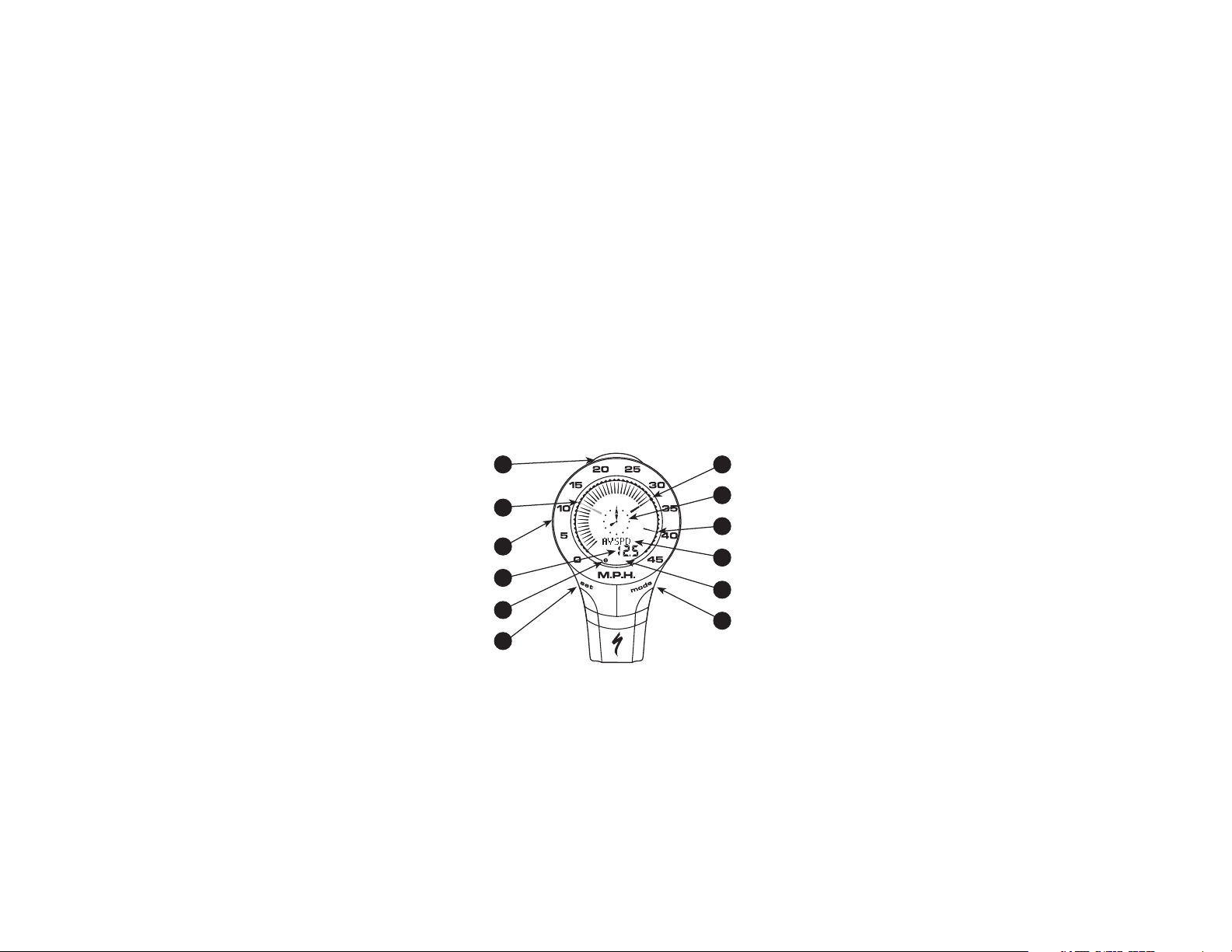
(Backlight/Start/Stop)
Average Speed Needle
Speed Indication Bezel
TOP Button
(Flashing)
3
12
9
Digital Display Area
Wheel Option Indicator
6
7
SET Button
2
Km/h
Current Speed Needle
10
Analog Clock
4
11
Maximum Speed Needle
5
Dot-Matrix Display Area
MPH or KM/H Indicator
8
MODE Button
1

6. Magnet with screw (1)
7. Adhesive backed magnet
8. Cadence magnet (1)
9. Cable tie wraps (6)
10. Mounting bracket sizing straps (3)
11. Speed Transmitter and mount (1)
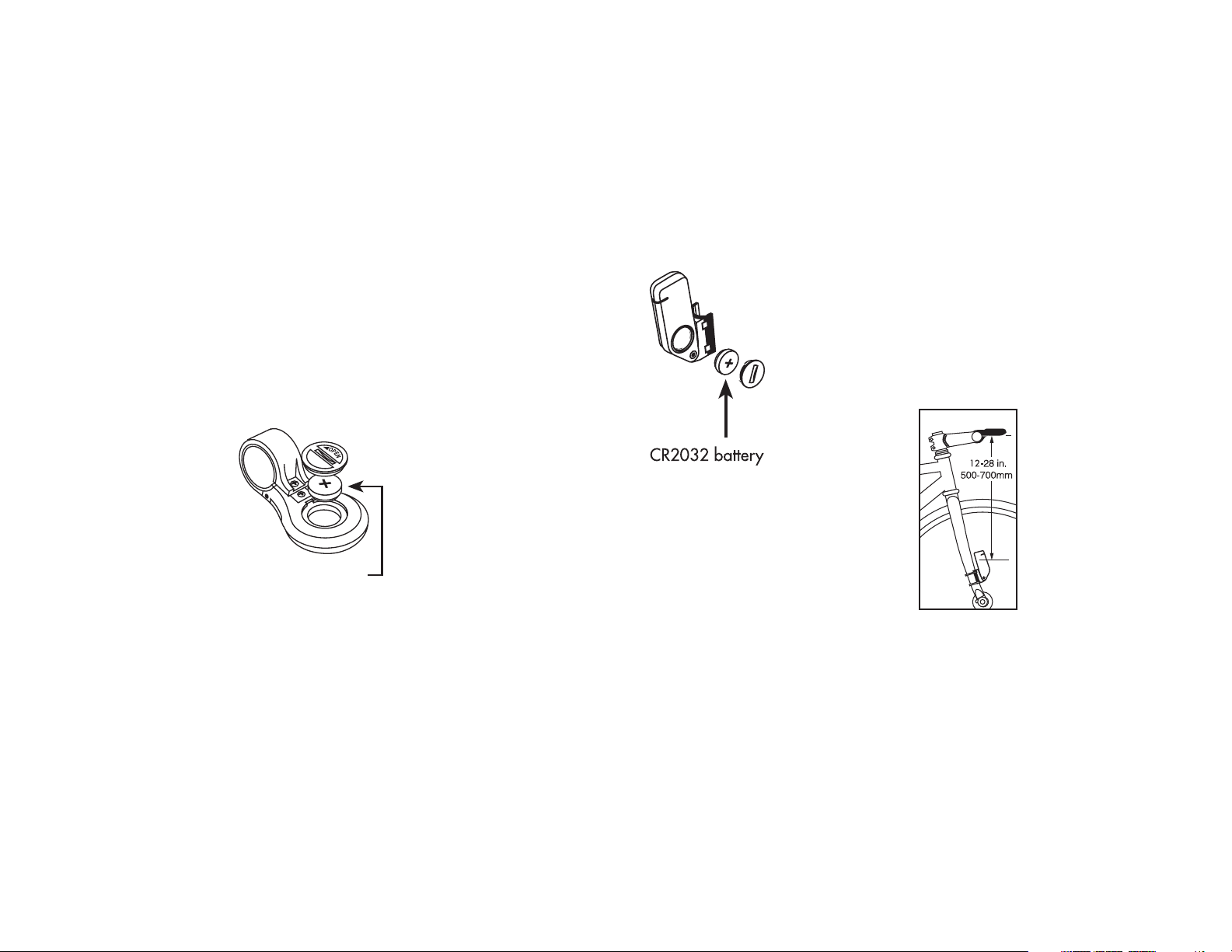
BATTERY INSTALLATION
AND REPLACEMENT
Before using your SpeedZone® Pro
Computer you will need to install the
battery. Turn the computer over so the
display is facing downward. Use a
coin to unthread the battery cap from
the computer. Install the battery
(model CR2032, Specialized P/N
481-3004) with the positive pole (+)
facing upward. Carefully thread the
battery cap back onto the case with a
3
This illustration describes the screen
display and buttons:
The following functions are available
on your SpeedZone® Pro:
• SPEED – Current Speed
• AVSPD – Average speed
• MXSPD – Maximum Speed
• TRIP – Trip Distance
• ODO – Odometer (total distance)
• ATM – Automatic Start/Timer
• TIMER – Stopwatch With Lap-timer
• CAD – Cadence
• AVCAD – Average Cadence
• MXCAD – Maximum Cadence
• INT – Interval Timer
• DIST – Distance Countdown
• ALTI – Current Altitude
• ALTI – Altitude Climbed
• %GRD – Inclinometer
• TEMP – Temperature in ˚C or ˚F
• Digital 12/24 Hour Clock
• Analog Clock
This computer also features:
• Wireless digital speed and cadence
sensing
• Five function LCD Display
• Second Wheel Option
• Easy Calibration Mode
• Water resistant housing
• 2 Year Warranty
• Backlit LCD display
The following items are included in
your SpeedZone® Pro package:
1. SpeedZone® Computer (1)
2. CR-2032 Lithium Battery (1)
3. Battery Door
4. Mounting bracket (1)
5. Cadence transmitter & mount (1)
2
1
4
10
3
2
9
6
7
8
5
11
MOUNTING
THE
SPEEDZONE®
PRO:
There are two
transmitters included with your
SpeedZone® Pro.
One transmitter is
for speed and the
other is for
cadence. Please
note that that they are marked with a
WHEEL (speed transmitter) icon or a
CRANK (cadence transmitter) icon. It
is very important that you mount them
in the correct locations on your bicycle. The wireless speed transmitter can
mount on the right or the left side of
the fork blade. The right side should
be used on large frames or when a
suspension fork is installed. The optimal distance between the computer
and the transmitter is 24 inches
(610mm). To reduce signal loss in
colder temperatures, the transmitter
should be mounted as close to the
computer as possible.
(Maximum mounting
distance is 47 inches/1200mm).
Assemble the transmitter to the mount
with the provided
screw. Use the tiewraps provided to
position the transmitter on the fork leg.
Do not tighten the tiewraps until final
5
coin. (See Figure 3A) If, after battery
replacement, the LCD display is blank
or shows incomplete digits, turn the
computer over and press the "AC"
button on the bottom of the case with
the tip of a pen or a paper clip. This
will clear all the data and re-start the
computer. If you need to
replace the battery,
make a note of your
odometer reading and
wheel circumference settings before removing it.
You can then re-enter the
data when you restart
the computer.
Replacing the
Transmitter Battery
The Wireless Transmitter comes with
the battery installed at the factory.
When the battery in the transmitter
needs replacing, it will transmit a signal to your SpeedZone® Pro and the
Dot Matrix Display Area
will show "LOBAT". If you
need to replace this battery, use a coin to
unthread the battery cap
from the transmitter housing. Install the battery
(model CR2032,
Specialized P/N 481-
3004) with the positive pole
(+) facing upward. (See
Figure 3B) Carefully thread the battery
cap back onto the case with a coin.
4
FIGURE 4.
SENSOR
PLACEMENT
FIGURE 3A.
FIGURE 3B.
CR2032 battery
road and mountain bike handlebars.
Attach the mount to the handlebar
using the Philips head screw provided. Tighten so that the bracket cannot
rotate on the handlebar. There are
several sizing shims provided to fit
different diameter bars. If you are
using the new 31.8mm diameter bars,
you will need to purchase the
31.8mm Handlebar Mount Kit
(Specialized P/N 4812-3100) from
your Specialized dealer. To install the
31.8mm diameter strap onto your
SpeedZone Pro, remove the two
Philips head screws from the bottom
of the computer and push out the
retaining pin with a small screwdriver
or a straightened paperclip. (See figure 6) Use caution not to lose the pin
once you have removed it. Install the
other mounting strap and reinsert the
pin and screws. To test for proper
installation of the magnet, transmitter
and computer, activate the computer
by pushing the ‘MODE’ (right side)
button. Pick up the front of the bicycle
and spin the front wheel. The "wheel
option" indicator will flash. If it does
not flash, check the sensor and magnet alignment. Realign as necessary
7
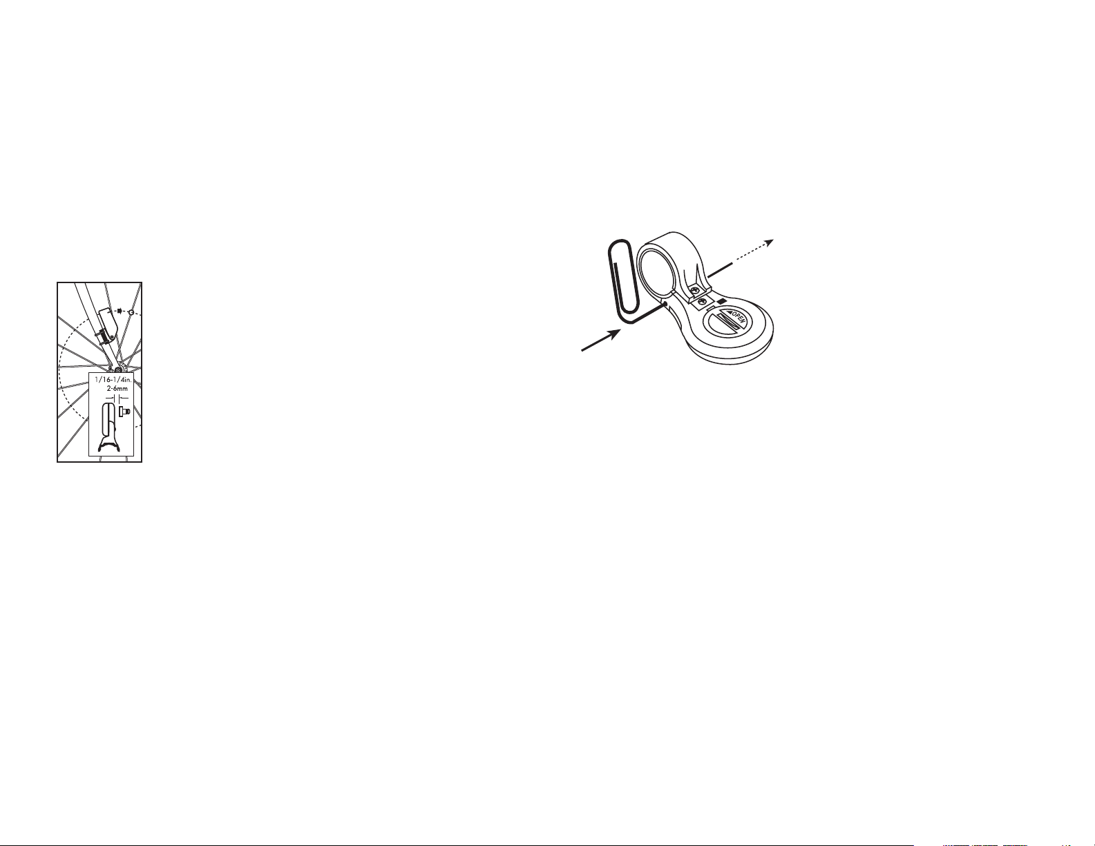
placement of the magnet is correct.
(See figure 4). For the best signal
reception, adjust
angle of the transmitter so that it is vertical. It is not necessary, or desirable to
aim the transmitter at
the computer.
Wheel magnets have
been provided for
both traditional
round spokes and
bladed (flat) aerody-
namic spokes.
For wheels with round spokes:
Attach the magnet to a spoke across
from the transmitter with the magnet
screw. The clearance between the
magnet and the transmitter should be
approximately 1/32"-1/16" (12mm). Tighten the magnet and transmitter. Do not over-tighten the magnet
screw. (See figure 5).
For wheels with bladed spokes;
Use some isopropyl (rubbing) alcohol
or a mild detergent to thoroughly
clean the spoke that you plan to
attach the magnet to. Remove the
backing from the adhesive tape and
firmly press the magnet onto spoke.
The tape uses a special pressure sensitive adhesive. To ensure a strong
bond, please wait at least 12 hours
for the adhesive to cure before riding
your bicycle.
Your SpeedZone Pro comes pre-configured with a strap to fit standard
6
FIGURE 5.
MAGNET
PLACEMENT
FIGURE 6. STRAP INSTALLATION
"SPEEDID". The "Dot-matrix Display
Area" may show a number (the code
of the digital speed transmitter) or "- -
-". If a number is shown, press the
mode button once and "- - -" will be
displayed. Now, spin your front wheel
to activate the transmitter. The
SpeedZone Pro will automatically
detect and store the speed transmitter
code. Press "SET" to resume operation. To calibrate the Cadence function, press the "MODE" button until
"CAD" is displayed. Then, press the
"TOP" button once. The Display will
now read "CADID". The "Dot-matrix
Display Area" may show a number
(the code of the cadence transmitter)
or "- - -". If a number is shown, press
the mode button once and "- - -" will
be displayed. Now rotate the cranks
of your bicycle backward to activate
the cadence transmitter. The
SpeedZone Pro will automatically
detect and store the transmitter code.
Press "SET" to resume operation.
These codes will be stored until the
battery is depleted or removed.
MOUNTING CADENCE
HARDWARE
In order to use the cadence option you
must install the cadence transmitter
provided with your SpeedZone® Pro.
This transmitter is marked with a
CRANK icon. The transmitter should
be fastened to the left chain stay of
your bicycle. Secure the transmitter
mount to the chain stay using the provided tie-wraps. Securely attach the
transmitter to the mount with the pro-
9
until the "wheel option" indicator
flashes while spinning the wheel.
IMPORTANT INSTALLATION NOTE:
Your SpeedZone® Pro computer uses
an advanced wireless digital transmission system. In order to operate correctly, it will need to "learn" the codes
from the speed and cadence transmitters. There is a simple calibration
process that must be done only when
you first install your SpeedZone® Pro
and any time you replace the battery
in the transmitter. (This should not be
necessary when replacing the only
computer batteries) Upon starting
your SpeedZone® Pro, press the
"MODE" button until "SPEED" is displayed. Then, press the "TOP" button
once. The Display will now read
8
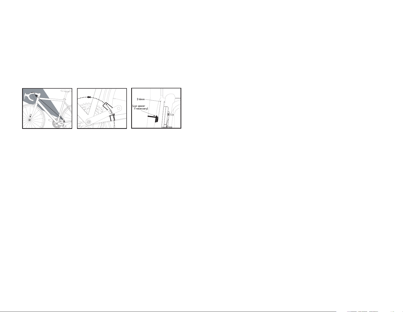
FIGURE 7. FIGURE 8. FIGURE 9.
SECURING HARDWARE FASTEN MAGNET CLEARANCE BETWEEN
TO CRANK ARM MAGNET AND SENSOR
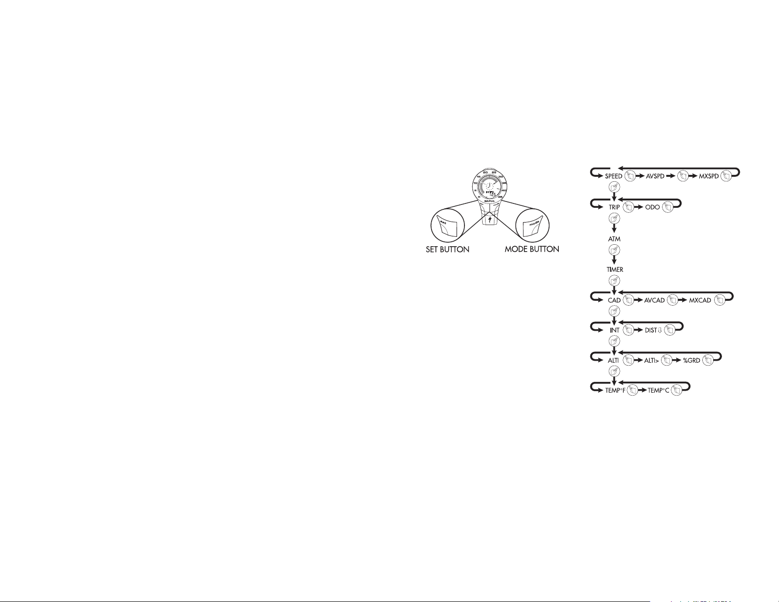
OPERATION AND
PROGRAMMING
When your SpeedZone® Pro has not
detected any speed input for 30 minutes, it will enter sleep-mode in order
to conserve battery power. During
sleep mode only the analog and digital clocks are displayed. You will need
to wake it up by pushing the "Mode",
"Set" or "Top" button once. In order to
operate your computer it must be
placed in various "modes" (i.e.
odometer mode, distance mode). The
computer can be cycled through these
modes by pressing the "MODE" button located on the right-hand side of
the housing. There are eight cycling
modes available: 1) Speed Mode, 2)
Distance Mode, 3) Auto-timer Mode,
4) Stopwatch Mode, 5) Cadence
Mode, 6) Countdown Mode, 7)
Altitude Mode and 8) Temperature
Mode. Within each mode there is a
side-mode that will allow you to
access additional information such as
average and maximum speeds. Use
the "SET" button to cycle through the
side-modes. Once you familiarize
yourself with the mode/side-mode
operation you will find it very easy to
navigate. The following flowchart out-
11
10
Km/h
1.
2.
3.
4.
5.
6.
7.
8.
vided screw. For the best signal
reception, adjust angle of the transmitter so that it is vertical (See figure
7). It is not necessary, or desirable to
aim the transmitter at the computer.
Next, attach the cadence magnet to
the inside of your crank arm directly
across from the sensor. Use a tiewrap to fasten the magnet to the
crank arm. (See figure 8). Do not
tighten the tie-wrap until final placement of the magnet is correct. The
clearance between the magnet and
the sensor should be approximately
1/32"-1/16" (1-2mm). (See figure
9). Tighten the magnet and transmitter.Note: The maximum mounting distance from Transmitter to computer
should not exceed 59 inches
(1500mm).
 Loading...