


400 SERIES AMPLIFIER BOX
PSRN4ANR1
PSRN4ANR2
Operating Modes
The primary operating modes are User Selectable tone, Yelp, Wail, Radio, PA, Horn Override, and a push-button Manual Override are available in all modes. All tones except Wail and Yelp for California Title 13 compliance may be disabled by programming the siren.
! WARNING
Do not install this product or route its wires in the air bag deployment area.
Doing so may cause damage to or reduce effectiveness of the air bag, or create projectile that could cause serious injury or death.
To determine air bag deployment area refer to vehicle manufacturer's manual.
1.800.338.7337 / www.soundoffsignal.com
MOUNTING
-Amplifier Installation-
Before drilling holes, check for clearance to prevent damage. Check both sides of the mounting surface before drilling and the be aware of any vehicle components or other vital parts that may be damaged during drilling.
Install grommets in any wire passage holes.
1.Slide ¼” hex head bolts into siren amplifier t-slots.
2.Place mounting brackets over bolts.
3.Thread ¼” lock nuts onto bolts and tighten down.
4.Use mounting bracket holes to secure amplifier
5.Install amplifier with clearance from other objects for improved ventilation.
1
2
4
-Microphone Bracket Installation-
A metal clip is provided for mounting the microphone. Choose a location convenient to the operator and away from any air bag deployment areas. Using the mounting clip as a template, mark the two holes to be drilled. Using a 1/8” drill bit, drill the two mounting holes. Install the two #6 screws provided with the bracket.
WIRING:
WARNING! All customer supplied wires connecting to the positive terminal of the battery must be sized to supply at least 125% of the maximum operating current and FUSED at the battery to carry that load.
Ensure the siren amplifier / relay unit is mounted in dry, protected environment.
TECHNICAL SPECIFICATIONS
Overall Dimensions: |
|
Control Panel: |
3.51” W x 6.89”H x 1.17”D |
Amplifier/Relay: |
2.62”H x 7.00”W x 6.51”D |
|
|
Input Voltage: |
10 - 16Vdc (negative ground) |
|
|
Boxed Weight: |
8 lbs. |
|
|
Operating |
-40°C to +50°C |
Temperature: |
|
Diagnostic LEDs: |
Speaker shorted/open, internal fuses open, |
|
communications faults |
Siren |
|
Input Current |
7 Amps @ 13.4 VDC (100W Speaker) |
|
14 Amps @ 13.4 VDC (2 x 100W speakers) |
|
|
Standby Current: |
|
Ignition ON: |
500mA |
Ignition OFF: |
<10mA |
|
|
Output Power: |
ETSA481: 1x100W RMS Max (11 Ohm speaker) |
|
ETSA482: 2x100W RMS Max (11 Ohm speaker) |
|
|
Audio Frequency: |
500-3 kHz |
|
|
Siren Frequency: |
675Hz - 1633Hz |
|
|
High Voltage |
Limits to <18V* |
Protection: |
*If siren tone is in progress, sound will continue |
|
during overvoltage. New siren tone will not |
|
activate if voltage is >18V |
|
|
Low Voltage |
Voltage<9.0V will cause siren output to cease |
Shutdown:: |
and will resume when system voltage is >9.5V |
|
|
|
Tone disable for California Title 13 compliance |
|
|
|
Auxiliary Input connection for remote manual or Hands |
|
Free operation |
|
|
Speaker Protection: |
Shorted, Open: Stop output signal, preserve Amp |
|
|
Light Control |
|
AUX button relays: |
9 total 10A max each circuit |
|
Total current not to exceed 50A for CN8 pin 5 |
|
|
|
2 of the 9 available for external Arrow control |
|
|
|
2 of the 9 have their source voltage switchable |
|
from internal to external via fuse location, see |
|
pg 5 |
|
|
Slide Switch Relays: |
3 total 20A max each circuit, |
|
Total current not to exceed 50A for CN8 pin 4 |
|
ETSA48(x)RSP 3.4.13 |
3
400 SERIES AMPLIFIER BOX |
|
|
|
|
Park Kill Input: (Yellow Wire) |
||||
PSRN4ANR1 |
|
|
|
|
|
|
The input will silence the siren tone when the input |
||
|
|
|
|
|
|
wire is activated. The input is typically connected |
|||
PSRN4ANR2 |
|
|
|
|
|
|
|||
|
|
|
|
|
|
to the transmission neutral safety switch. If this |
|||
|
|
|
|
|
|
|
feature is required, the installer needs to determine |
||
|
|
|
|
|
|
|
if the signal wire from the neutral safety switch |
||
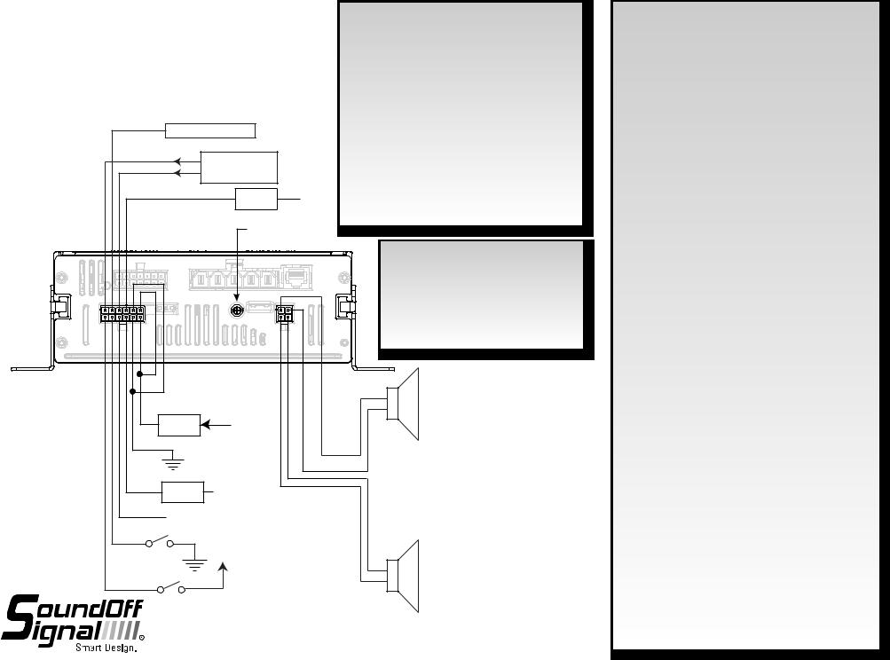
SIREN AUDIO WIRING |
|
|
|
|
|
|
is switching the +V or ground side of the circuit. |
||
|
|
|
|
|
|
Refer to the programming instructions on how to set |
|||
|
|
|
|
|
|
|
the park kill polarity on the siren. Extend the park |
||
|
|
|
|
|
|
|
kill input wire from the siren amplifier to the neutral |
||
YELLOW |
NEUTRAL SAFETY SWITCH |
|
|
|
|
safety switch using a minimum 22ga. Wire. Park kill |
|||
|
|
|
|
|
Vin Low is < 5Vdc. |
|
|||
|
|
|
|
|
|
|
|
||
BLUE |
|
RADIO |
|
|
|
|
Ignition Input: (Orange/Black Wire) |
||
BLUE |
|
|
|
|
|
The input is required to enable the siren system. |
|||
|
REBROADCAST |
|
|
|
|
||||
|
|
|
|
|
|
Locate the wire on the vehicle which provides +V |
|||
|
|
|
|
|
|
|
|||
ORANGE/BLACK |
3 amp |
|
|
|
|
when the ignition switch is turned ON. Extend the |
|||
|
IGNITION |
|
ignition input wire as needed using a minimum of |
||||||
|
|
Fuse |
|
|
|||||
|
|
|
|
|
|
|
22ga. Wire and tap into the vehicle ignition wire. |
||
|
|
RADIO REBROADCAST |
|
|
|
|
|
||
|
|
OUPUT LEVEL ADJUST |
|
|
|
|
|
||
|
|
|
|
|
|
|
|
Wire capacity requirements for siren |
|
|
|
|
|
|
|
|
|
amplifier (incoming power)-each supply and |
|
|
|
|
|
|
|
|
|
ground wire. |
|
|
|
|
|
|
|
|
|
0-10 Feet: |
14 AWG |
CN6 |
|
|
|
|
|
|
|
10-20 Feet: 12 AWG |
|
|
|
|
|
|
|
|
|
20-30 Feet: 10 AWG |
|
|
|
CN2 |
|
|
|
|
|
30+ Feet: |
Consult Factory to determine |
|
|
|
|
BLACKORANGE/ |
|
|
ORANGE/BLACK |
|
requirements |
|
|
GREEN |
BLACKGREEN/ |
ORANGE |
ORANGE |
SPKR A |
|||
|
|
|
|
|
|
|
|
||
|
|
|
|
|
|
|
|
PRIMARY |
|
|
|
|
|
|
|
|
|
ETSA481 OR |
|
RED |
20 amp |
|
|
|
|
|
|
ETSA482 |
|
+V |
|
|
|
|
|
|
|
||
|
Fuse |
|
|
|
|
|
|
|
|
|
|
|
|
|
|
|
|
|
|
BLACK |
|
|
|
|
|
|
|
|
|
|
|
|
|
|
|
|
|
USE ONE 11 OHM |
|
WHITE |
5 amp |
Horn Ring Out |
|
|
|
|
|
SPEAKER PER OUTPUT |
|
WHITE/ |
Fuse |
|
|
|
|
|
|
|
|
|
|
|
|
|
|
|
|
|
|
BLACK |
Horn Ring In |
|
|
|
|
|
GREEN/BLACK |
|
|
|
|
|
|
|
GREEN |
|
|
||
Auxiliary |
+V |
|
|
|
|
|
|||
VIOLET |
|
|
|
|
|
|
|
|
|
|
|
|
|
|
|
|
|
SPKR B |
|
|
|
|
|
|
|
|
|
SECONDARY |
|
GRAY |
|
|
|
|
|
|
|
ONLY ON |
|
|
|
|
|
|
|
|
ETSA482 |
||
Backlight
1.800.338.7337 / www.soundoffsignal.com
Auxiliary Input: (Violet Wire)
The input is an optional input which will remotely activate the siren when the auxiliary input wire is connected to ground. If this feature is needed, connect the auxiliary input wire to a switch which provides a ground connection when activated. *Park kill disables this option.
Radio Rebroadcast Input: (Blue Wires)
The 2 – 18ga blue wires on the 12 pin Molex connector are used to connect your two-way radio’s external speaker through the siren amplifier and broadcast through the warning siren speaker and is optional. Radio Rebroadcast will not work with remotely amplified speakers due to the signal amplitude being too low. Locate the 2 wires that connect the external speaker to the two-way radio. T-tap one blue wire into the one of
the external speaker wires. T-tap the other blue wire into the other external speaker wire. If the blue wires need to be extended, use a minimum of 20ga. Wire. The Radio Rebroadcast volume must be adjusted prior to placing vehicle into service. Set the volume of the two-way radio to the normal operating level. Press the Radio Rebroadcast push-button on the siren control panel. With a small screwdriver, adjust the radio rebroadcast volume potentiometer located on the back of the siren amplifier to obtain the proper volume out the speaker. Turn potentiometer clockwise to increase volume and counter-clockwise to decrease volume.
Horn Ring Input: (White + White/Black Wire)
The input will allow the operator to control the siren function by pressing the vehicle horn ring. Refer to programming settings for specific configuration options. Refer to wiring diagram for details on how to connect the horn ring input wires to the vehicle’s horn ring wiring. If this feature is required, the installer needs to determine if the signal wire from the horn ring is switching +V or ground side of the circuit. Refer to programming instructions on how to set the horn ring polarity on the siren. Extend the horn ring input wires from the siren amplifier to the horn ring switch using a minimum of 18ga wire. The horn ring circuit is capable of handling a maximum of 5 amps and must be fused by the installer.
Siren Speaker Output: (Orange + Orange/Black Wires), (Green + Green/Black wires) Route the Orange and Orange/Black wires from the 4 position connector to the siren speaker. Use a minimum of 18ga. wire to extend the wires as needed. Connect the Orange wire to the primary Speaker High wire. Connect the Orange/Black wire to the primary Speaker Low wire. For ETSA482 only connect the Green wire to the secondary Speaker High Wire. Connect the Green/Black wire to the secondary Speaker Low Wire.
Backlight Input: (Gray Wire)
The input will turn on the backlighting of the control panel whenever +V is applied to the backlight input wire.
ETSA48(x)RSP 3.4.13
4

400 SERIES AMPLIFIER BOX
PSRN4ANR1 |
RED/ BLACK |
|
PSRN4ANR2 |
||
GREEN/ BLACK |
RED/ WHITE
POWERED |
|
ORANGE |
OUTPUT WIRING |
|
YELLOW |
|
|
BROWN |
|
|
BLUE |
|
|
CN3 |
Auxiliary Push Button #8 |
GREEN/WHITE |
|
Normally Closed Output |
|
|
N.C. |
|
|
Relay #8 Input |
GREEN |
|
|
||
Relay #7 Input |
RED |
|
|
||
Relay #9 Output for |
|
GREY |
2 wire Arrow Control Interface |
|
|
Auxiliary Push Button #6 Output |
VIOLET |
|
|
||
Auxiliary Push Button #5 Output |
WHITE |
|
|
||
NORMALLY OPEN
CONTACT RELAY
+V when Ignition |
|
1 1 |
Switch is ON |
1 Amp |
3 |
|
5

2 2
From Siren
Switch Output
1.800.338.7337 / www.soundoffsignal.com
Auxiliary Push-Button 7 Normally Open Output |
|
||
Auxiliary Push-Button 8 Normally Open Output |
|
||
CONTROL PANEL |
|||
Auxiliary Push-Button 7 Normally Closed Output |
|||
PSRN4CTRL1 |
|||
Push-Button 4 Output |
|
||
|
OR |
||
Push-Button 3 Output |
RJ45 Cable to Control Panel |
||
HANDHELD REMOTE |
|||
Push-Button 2 Output |
|
||
|
PSRNHHC1 |
||
Push-Button 1 Output |
|
|
|
|
|
||
|
CN5 |
Wire capacity requirements for Relay |
|
CN8 |
incoming power supply for each wire |
||
|
|
|
|
|
|
|
Wire Length |
Minimum Wire Gauge |
||
5 |
4 |
3 |
2 |
1 |
|
0-10 Feet |
10 AWG |
||
|
|
|
|
|
|
10-15 Feet |
|
8 AWG |
|
|
|
|
|
|
|
15-25 Feet |
|
6 AWG |
|
|
|
|
|
|
|
25+ Feet |
Consult Factory |
||
|
RED |
RED |
BLUE |
GREEN |
YELLOW |
Slide Switch Level 3 Output |
|
|
|
|
|
|
|
|
|
|
|
|
|
|
|
|
|
|
|
Slide Switch Level 2 Output |
|
|
|
|
|
|
|
|
|
Slide Switch Level 1 Output |
FUSE CHART |
||
|
|
|
|
|
50A |
|
|||
|
|
|
|
|
+ V |
LOCATION |
RATING |
||
|
|
|
|
|
FUSE |
|
|||
|
|
|
|
|
50A |
+ V |
FB-8 |
|
10A |
|
|
|
|
|
|
|
|
||
|
|
|
|
|
FUSE |
|
FB-7 |
|
10A |
|
|
|
|
|
|
|
FB-4 |
|
10A |
|
|
|
|
|
|
|
FB-3 |
|
10A |
|
|
|
|
|
|
|
FB-2 |
|
10A |
|
|
|
To Device requiring power |
FB-1 |
|
10A |
|||
|
|
|
|
|
|
||||
|
|
|
only when Ignition Switch |
FB-5 |
|
10A |
|||
|
|
|
is on |
|
|
FB-6 |
|
10A |
|
|
|
|
|
|
|
|
|
||
|
|
|
|
|
|
|
FB-9 |
|
10A |
|
|
|
|
|
|
|
FS-1 |
|
20A |
FS-2 20A
NOTICE: |
FS-3 |
20A |
When an output is connected to a device which is required to function only when ignition switch is ON, a relay needs to be installed in-line with the siren switch output to ensure an operator can’t activate the device without the ignition switch ON.
See wiring diagram details:
Internal Relay Board Fuse replacement:
To replace fuses:
1.Remove power connectors CN8 and CN6 or remove power to unit.
2.Remove unit from console or obtain access to full top of unit.
3.Depress snaps on top cover and lift open.
4.See chart below for output fuse locations and ratings.
5.Fuse Ratings: Replace with same rated part.
6.Close cover, reinstall connectors and reinstall unit in console.
The button outputs 7 and 8 have the ability to receive power from an independent external power source or from the internal +V as supplied to CN8. Both of these outputs use a separate internal 10A mini-ATO fuse which rely on position to determine the source selection. Each fuse may be placed in one of 2 locations. See diagram below.
*If the fuse is placed in the fuse holder near the back edge of the PCB that output will be powered from an external source, labeled “relay #(x) input” on CN3.
**If the fuse is placed in the fuse holder away from the back edge of the PCB that output will be powered from the internal +V source that comes from CN8 pin 5.
FUSE LOCATIONS ON RELAY PCB
**INTERNAL
*EXTERNAL
8 |
7 |
4 |
3 |
2 |
1 |
5 |
6 9 |
1 |
2 |
3 |
AUXILARY PUSH BUTTON |
SLIDE SWITCH |
|||||||||
Slide Switch Level Outputs 1-3 and Button Outputs 1-6 are active high (vehicle supply level).
ETSA48(x)RSP 3.4.13
5
 Loading...