


nFORCE™ LED Lightbar
IMPORTANT NOTICE TO INSTALLER: Make sure to read and understand all instructions and warnings before proceeding with the installation of this product. Ensure that the manual and any warning cards are delivered to the end user of this equipment. Proper installation of the lightbar requires the installer to have a thorough knowledge of automotive electronics, systems, and procedures. Lightbars provide an essential function of an effective visual warning system. The use of the lightbar does not insure that all drivers can or will abide by or react to an emergency warning signal, especially at high
rates of speeds or long distances. The operator of the vehicle must never take the right of way for granted and it is the operator’s responsibility to proceed safely. The effectiveness of the lightbar is highly dependant on the correct mounting and wiring. The installer must read and follow the manufacturer’s installation instructions and warnings in the manual. The vehicle operator should verify daily that the lightbar is securely fastened to the vehicle and properly functioning before operating vehicle. The lightbar is intended for use by authorized personnel only. It is the user’s responsibility to ensure they understand and operate the emergency warning devices in compliance with the applicable city, state and federal laws and regulations. SoundOff Signal assumes no liability for any loss resulting from the use of this warning device.
Components/Contents
Standard Equipment:
1 - nForce™ LED Lightbar built to your specifications
1 - Breakout Box
1 - 24 Pin Harness
Other Parts that may be included depending on your configuration:
1 - Vehicle Specific Hook Kit w/ Hardware*
2 - Fixed Height Mounting Brackets w/ Hardware or
1 - Flat Mount Hardware Kit or
2 - Headache Brackets w/ Hardware
*Kits will vary with each lightbar depending on vehicle specified on order form.
Unpack Lightbar
1.Remove the lightbar from box and packaging.
2.Save packaging for later shipping.
3.Check components/contents.
4.Please reference these instructions for proper wiring and installation.
Tools Required for Installation
•7/16“ Socket with ratchet
•Phillips Head Screwdriver
|
TABLE OF CONTENTS |
PAGE |
CONTENT |
1 |
COMPONENTS/ CONTENTS |
2 |
MODULE SPECIFICATIONS |
3TECHNICAL/ POWER SPECIFICATIONS
4FIXED HEIGHT BRACKETS AND HOOK MOUNTING
5GASKET MOUNTINT INSTRUCTIONS
6-9 |
ELECTRICAL INSTALLATION |
10 |
CONTROL HARNESS |
11 |
LIGHT MODULE WIRE HARNESS LOCATIONS |
12-13 |
DRIVER MODULE REPLACEMENT |
14NFORCE TROUBLESHOOTING
15CONNECTION OF BREAKOUT BOX TO SOUNDOFF
SIGNAL SIRENS 16 REPLACEMENT PARTS
17 WARRANTY AND RETURN GOODS PROCEDURE
Important Information:
•Warning devices are strictly regulated and governed by Federal, State and Municipal ordinances. These devices shall be used ONLY on approved vehicles. It is the sole responsibility of the user of these devices to ensure compliance.
•DO NOT install this product or route any wires in the Air Bag Deployment Zone. Refer to your vehicle Owner’s Manual for the location of any air bag deployment zones.
•DO NOT connect this device to a strobe power supply. This product is self-contained and does not require an external power supply.
! WARNING
This product contains high intensity LED devices. To prevent eye damage, DO NOT stare into the light beam at close range.
1.800.338.7337 / www.soundoffsignal.com |
IMPORTANT INFORMATION: |
Warning devices are strictly regulated and governed by Federal, State and Municipal ordinances. These devices shall be used ONLY on approved vehicles. It is the sole responsibility of the user of these devices to ensure compliance.
To review our Limited Warranty Statement & Return Policy for this or any SoundOff Signal product, visit our website at www.soundoffsignal.com/sales-support.
If you have questions regarding this product, contact Technical Services, Monday - Friday, 8 a.m. to 5 p.m. at 1.800338.7337 (press #4 to skip the automated message). Questions or comments that do not require immediate attention may be emailed to techservices@soundoffsigal.com.
SUPERIOR CUSTOMER RELATIONSHIPS. SMARTLY DESIGNED LIGHTING & ELECTRONIC SOLUTIONS.
1. |
|
nForce Lightbar 05.14 |
|
|

nFORCE™ LED Lightbar
6 LED Single, Dual & Tri Color Inboard Module
INPUT VOLTAGE RANGE: 10-16Vdc
CURRENT DRAW: 0.5 Amps @ 12.8 Vdc (Flashing)
1.0 Amps @ 12.8 Vdc (Steady On)
WATTAGE: 6.4W (Flashing)
9 LED Single Color Inboard Module
INPUT VOLTAGE RANGE: 10-16Vdc
CURRENT DRAW: 0.75 Amps @ 12.8 Vdc (Flashing)
1.5 Amps @ 12.8 Vdc (Steady On)
WATTAGE: 9.6W (Flashing)
6 LED Single Color Takedown Module
INPUT VOLTAGE RANGE: 10-16Vdc
CURRENT DRAW: 1 Amps @ 12.8 Vdc (Steady On)
WATTAGE: 12.8 (Steady On)
12 LED Single, Dual & Tri Color Corner Module
INPUT VOLTAGE RANGE: 10-16Vdc
CURRENT DRAW: 1 Amps @ 12.8 Vdc (Flashing)
2 Amps @ 12.8 Vdc (Steady On)
WATTAGE: 12.8W (Flashing)
12 LED Single, Dual & Tri Color Corner Module w/Alley
INPUT VOLTAGE RANGE: 10-16Vdc
CURRENT DRAW: 1 Amps @ 12.8 Vdc (Flashing) 2.5 Amps @ 12.8 Vdc (Steady On)
WATTAGE: 12.8 (Flashing)
18 LED Single Corner Module
INPUT VOLTAGE RANGE: 10-16Vdc
CURRENT DRAW: 1.5 Amps @ 12.8 Vdc (Flashing)
3 Amps @ 12.8 Vdc (Steady On)
WATTAGE: 19.2W (Flashing)
18 LED Single Corner w/Alley
INPUT VOLTAGE RANGE: 10-16Vdc
WARNING CURRENT DRAW: 1.5 Amps @ 12.8 Vdc (Flashing) 3.5 Amps @ 12.8 Vdc (Steady On)
WARNING WATTAGE: 19.2W (Flashing)
ALLEY CURRENT DRAW: .25 Amps @ 12.8 Vdc (Flashing)
.5 Amps @ 12.8 Vdc (Steady On) ALLEY WATTAGE: 6.4W (Steady On)
|
FLASHING = AVERAGE |
IMPORTANT INFORMATION: |
STEADY ON (100%) = PEAK |
|
Warning devices are strictly regulated and governed by Federal, State and Municipal ordinances. These devices shall be used ONLY on approved vehicles. It is the sole responsibility of the user of these devices to ensure compliance.
To review our Limited Warranty Statement & Return Policy for this or any SoundOff Signal product, visit our website at www.soundoffsignal.com/sales-support.
If you have questions regarding this product, contact Technical Services, Monday - Friday, 8 a.m. to 5 p.m. at 1.800338.7337 (press #4 to skip the automated message). Questions or comments that do not require immediate attention may be emailed to techservices@soundoffsigal.com.
SUPERIOR CUSTOMER RELATIONSHIPS. SMARTLY DESIGNED LIGHTING & ELECTRONIC SOLUTIONS.
2. |
|
nForce Lightbar 05.14 |

nFORCE™ LED Lightbar
TOP VIEW WITH COVERS ON
REAR
FRONT
TOP VIEW WITH COVERS OFF
REAR
FRONT
INBOARD LED MODULES |
CORNER MODULE |
|
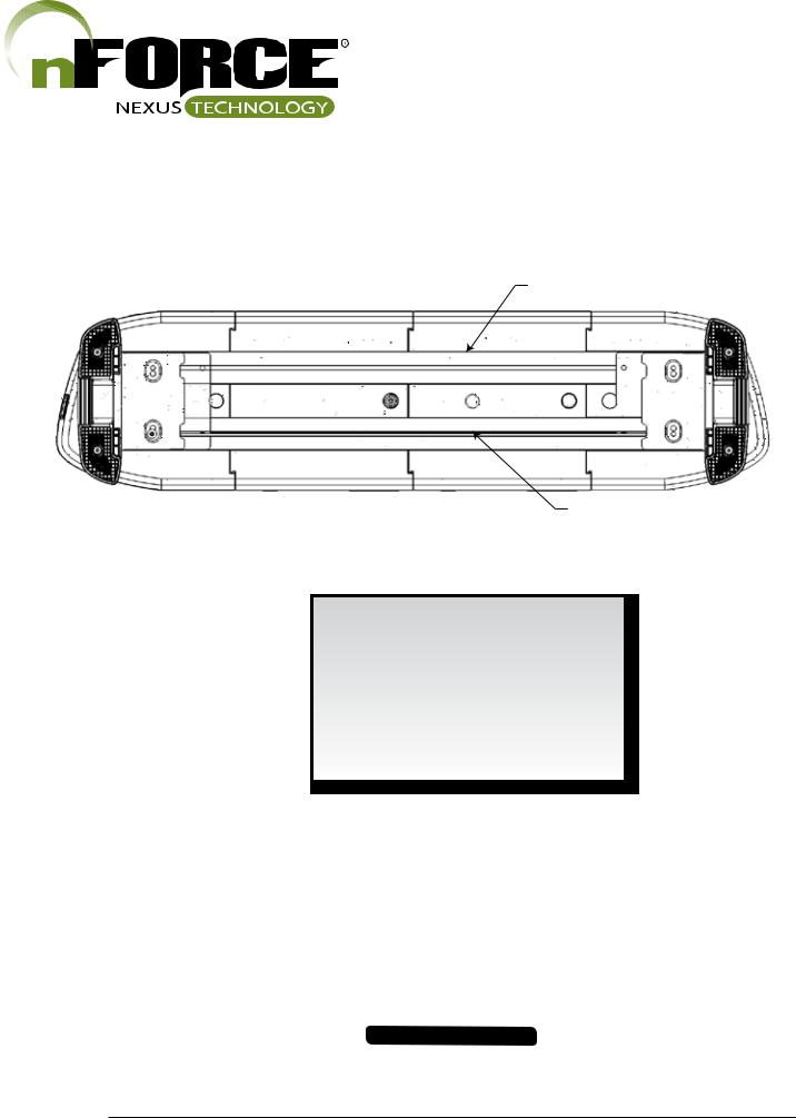
BOTTOM VIEW
REAR
FRONT |
Wire Exit Holes |
|
TECHNICAL SPECIFICATIONS
|
Aluminum Base, polycarbonate |
||
Material: |
outer lenses, ASA/PC top cover. |
||
|
|
||
Roof Attachments: |
1/4" bolt Stainless A2 |
||
|
|
|
|
Operating Temperature: |
|
-40º to +65º C |
|
|
|
|
|
LENGTH |
# OF INBOARDS |
DIMENSIONS |
|
|
|
|
|
24" |
2 |
|
|
|
|
|
|
36" |
4 |
|
|
|
|
|
|
42" |
5 |
|
|
|
|
|
12"D x 2.5"H |
48" |
6 |
|
|
|
inboard |
||
|
|
|
|
|
|
|
|
54" |
7 |
|
|
|
|
|
|
60" |
8 |
|
|
|
|
|
|
72" |
10 |
|
|
|
|
|
|
POWER SPECIFICATIONS
Input Voltage Range: |
|
10 -16 Vdc |
|
||
|
|
|
|
|
|
Light Bar |
Current Draw |
Power Consumption |
|||
Component |
(Average = Flashing) |
(Watts) |
|||
|
|
|
|
|
|
Standby Current |
Ignition ON |
Ignition OFF |
Ignition ON |
Ignition OFF |
|
0.010 Amps |
0.002 Amps |
0.13 Watts |
0.03 Watts |
||
|
|||||
Reverse Polarity |
|
Protected |
|
||
|
|
|
|
|
|
Load Dump |
|
Protected |
|
||
|
|
|
|
|
|
Wiring |
Power Cable 15ft 14 AWG Wires, (+) Red, (-) Black |
||||
|
Data Cable 25ft RJ-45 Type |
|
|||
|
|
|
|||
|
|
|
|
|
|
IMPORTANT INFORMATION:
Warning devices are strictly regulated and governed by Federal, State and Municipal ordinances. These devices shall be used ONLY on approved vehicles. It is the sole responsibility of the user of these devices to ensure compliance.
To review our Limited Warranty Statement & Return Policy for this or any SoundOff Signal product, visit our website at www.soundoffsignal.com/sales-support.
If you have questions regarding this product, contact Technical Services, Monday - Friday, 8 a.m. to 5 p.m. at 1.800338.7337 (press #4 to skip the automated message). Questions or comments that do not require immediate attention may be emailed to techservices@soundoffsigal.com.
SUPERIOR CUSTOMER RELATIONSHIPS. SMARTLY DESIGNED LIGHTING & ELECTRONIC SOLUTIONS.
3. |
|
nForce Lightbar 05.14 |

nFORCE™ LED Lightbar |
|
|
|
|
|
|
T-Slot Attachment x2 |
|
|
|
|
|
(1st slid into extrusion) |
|
|
|
|
|
1.5° Wedge |
|
|
|
|
|
Metal Nut Bracket |
|
Figure 1. |
|
|
|
Mounting Foot |
|
|
Hook Bracket |
FIXED HEIGHT BRACKETS AND |
|
|
|
Cover Door |
||
|
Split Ring Lock Washer |
Hook Bracket Bolt |
HOOK MOUNTING |
||
|
|
|
1. Keeping the lightbar level with the road, attach Mount- |
||
|
|
|
|
|
|
|
|
|
|
|
ing Feet to the roof of the vehicle using the 2 supplied |
Flat Washer |
|
|
|
|
T-Slot bolts. If the lightbar needs to be leveled, a 1.5° |
|
|
|
|
wedge has been provided. |
|
|
|
|
|
|
|
Lock Nut |
Flat Washer |
|
|
2. Place lightbar centered on the roof, and hold brackets |
|
|
|
|
|
#8-1/2" Truss Head |
|
|
Rubber Pad |
|
|
up to the lightbar. A 1/4" to 1/2" gap should be between |
|
|
|
|
Sheetmetal screw |
||
|
|
Hook Bracket |
the hook bracket and front wall of the mounting foot prior |
||
|
|
|
|||
|
|
|
|
|
to putting any tension on the hook bracket bolt (See Fig- |
|
|
|
|
|
ure 3). Adjust the mounting foot position to accomodate |
|
|
|
|
|
for this gap. |
Figure 2. |
|
|
|
|
3. Tighten hook bracket bolts with max torque 10in-lbs. |
|
|
|
|
|
|
|
|
|
|
|
DO NOT OVERTIGHTEN! Bar is secure once split |
|
|
|
|
|
lock washer has been compressed. Using holes in the |
|
|
|
|
|
hook bracket as a template, drill 4 holes in the roof us- |
|
|
|
|
|
ing the appropriate size drill. Secure hook bracket to roof |
|
|
|
|
|
with 4 screws on each side. |
|
|
1/4" - 1/2" Gap Required |
4. Install the cover door over the hook bracket bolt to fin- |
||
|
|
|
|
|
|
|
|
|
|
|
ish the assembly. Place tab of one side into place and |
|
|
|
|
|
then push the second tab into place with a flat-head |
|
|
|
|
|
screw driver. |
! |
WARNING |
Route wires only in locations that are not subjected to |
|
potential wear. Make sure to avoid routing wires in the |
|
deployment area of your air bag. Refer to your vehicle’s |
|
owner’s manual for airbag deployment zone. |
|
Figure 3.
IMPORTANT INFORMATION:
Warning devices are strictly regulated and governed by Federal, State and Municipal ordinances. These devices shall be used ONLY on approved vehicles. It is the sole responsibility of the user of these devices to ensure compliance.
To review our Limited Warranty Statement & Return Policy for this or any SoundOff Signal product, visit our website at www.soundoffsignal.com/sales-support.
If you have questions regarding this product, contact Technical Services, Monday - Friday, 8 a.m. to 5 p.m. at 1.800338.7337 (press #4 to skip the automated message). Questions or comments that do not require immediate attention may be emailed to techservices@soundoffsigal.com.
SUPERIOR CUSTOMER RELATIONSHIPS. SMARTLY DESIGNED LIGHTING & ELECTRONIC SOLUTIONS.
4. |
|
nForce Lightbar 05.14 |
|
nFORCE™ LED Lightbar
REAR
FRONT
Black 3/8" dia. foam gasket location - Cut to fit
Grey gasket location - Cut to fit
GASKET MOUNTING INSTRUCTIONS
1.Cut the Black 3/8" round diameter foam gasket to fit your lightbar
2.Install the Black 3/8" round diameter foam gasket in the back slotof the lightbar as shown above
3.Install the Grey gasket in the front slot of the lightbar as shown above
IMPORTANT INFORMATION:
Warning devices are strictly regulated and governed by Federal, State and Municipal ordinances. These devices shall be used ONLY on approved vehicles. It is the sole responsibility of the user of these devices to ensure compliance.
To review our Limited Warranty Statement & Return Policy for this or any SoundOff Signal product, visit our website at www.soundoffsignal.com/sales-support.
If you have questions regarding this product, contact Technical Services, Monday - Friday, 8 a.m. to 5 p.m. at 1.800338.7337 (press #4 to skip the automated message). Questions or comments that do not require immediate attention may be emailed to techservices@soundoffsigal.com.
SUPERIOR CUSTOMER RELATIONSHIPS. SMARTLY DESIGNED LIGHTING & ELECTRONIC SOLUTIONS.
5. |
|
nForce Lightbar 05.14 |
|
nFORCE™ LED Lightbar
Featured Highlights & Terminology: ELECTRICAL INSTALLATION
Mode Select: The nForce Lightbar is equipped with 2 selectable pattern configuration modes via the Mode Select Input. Default is Mode 1 where the input is floating, Mode 2 is in use when the input activated. This feature allows 2 complete sets of patterns to be programmed into the Lightbar's non-volatile memory. Once programming configuration is complete, the Mode can be changed “on-the-fly” by an activation switch which applies voltage to the Mode 2 input wire.
Cruise Mode: Allows the user to program any light group(s) to “Glow” when this feature is activated. For dual / tri color bars, the color for each light group is selectable.
Directional Arrow Built-in: The directional controller is built-in w/ 6 arrow patterns for each of the 3 modes (left arrow, right arrow, and center out arrow) and the color is selectable for dual / tri color bars
Scene Light Mode: Allows the user to program any Light Head Group(s) to turn on steady when this feature is activated to provide additional scene lighting. The activation of this input also activates the Takedown function
Stop / Tail / Turn Mode: Allows the user to program any Light Head Group(s) to turn operate in 2 levels of intensity for tail and stop/turn functions.
Low Power Mode: Operates lighting at reduced intensity.
! WARNING
ALL CUSTOMER SUPPLIED POWER WIRES CONNECTING TO THE POSITIVE (+) OR NEGATIVE (-) BATTERY
TERMINAL OR LOCAL CHASIS GROUND (-) MUST BE SIZED TO SUPPLY AT LEAST 125% OF THE MAXIMUM
CURRENT AND PROPERLY FUSED AT THE POWER SOURCE WITH APPROPIATELY RATED FUSE.
Power Cable:
1.Route lightbar power cables as close to vehicles power source (battery) as possible.
2.Install a maximum of 30Amp Fuse (customer supplied) to the end of the RED wire of the Lightbar Power Cable. a. Remove the fuse before connecting any wires to the battery.
b. DO NOT USE CIRCUIT BREAKER OR FUSIBLE LINK.
3.Connect the other end of the Fuse to the POSITIVE (+) terminal of the battery.
a. Do NOT use any more than 2ft of wire between the battery terminal and the fuse and ensure the wire is protected and secured from being cut into; this is non-fused wire.
4. Connect the BLACK wire to the factory chassis ground right next to the battery.
Control (Data) Cable:
1.Route Lightbar Control Cable to the location where all controlling equipment will be, i.e. switch box, center console area.
2.Locate the Breakout Box in the same area to connect jumpers from the switching equipment to the breakout box.
3.Refer to breakout box hookup table on page 9.
Initial Power up Test:
1.Plug RJ-45 power / data plug into ‘Lightbar’ connector on the breakout box.
2.Apply power to pink/white ignition wire on breakout box. See table 1 on page 9.
3.Observe the GREEN Data Link indicator LED on the Breakout Box; the Green LED will be ON showing power is connected.
4.The Red indicator LED on the breakout box will be steady ON whenever any of the input wires are active or data is received from a siren.
Low Power (Standby) Mode (reduced standby current)
If there is no input to the breakout box the lightbar will go into a “standby” mode. The standby mode is a low power mode that is used to extend the life of your battery. The lightbar will awaken from the standby mode if any input is activated on the breakout box.
IMPORTANT INFORMATION:
Warning devices are strictly regulated and governed by Federal, State and Municipal ordinances. These devices shall be used ONLY on approved vehicles. It is the sole responsibility of the user of these devices to ensure compliance.
To review our Limited Warranty Statement & Return Policy for this or any SoundOff Signal product, visit our website at www.soundoffsignal.com/sales-support.
If you have questions regarding this product, contact Technical Services, Monday - Friday, 8 a.m. to 5 p.m. at 1.800338.7337 (press #4 to skip the automated message). Questions or comments that do not require immediate attention may be emailed to techservices@soundoffsigal.com.
SUPERIOR CUSTOMER RELATIONSHIPS. SMARTLY DESIGNED LIGHTING & ELECTRONIC SOLUTIONS.
6. |
|
nForce Lightbar 05.14 |
|
 Loading...