

Page 1

GREAT SOUND MADE EASY
User Guide
Page 2

IMPORTANT
Please read this manual carefully before using
your mixer for the first time.
© Harman International Industries Ltd. 2003
All rights reserved
Parts of the design of this product may be protected by worldwide
patents.
Part No. ZM10107-01
Issue: 1
Soundcraft is a trading division of Harman International Industries Ltd.
Information in this manual is subject to change without notice and does
not represent a commitment on the part of the vendor. Soundcraft
shall not be liable for any loss or damage whatsoever arising from the
use of information or any error contained in this manual.
No part of this manual may be reproduced, stored in a retrieval system,
or transmitted, in any form or by any means, electronic, electrical,
mechanical, optical, chemical, including photocopying and recording, for
any purpose without the express written permission of Soundcraft.
Harman International Industries Limited
Cranborne House
Cranborne Road
POTTERS BAR
Hertfordshire
EN6 3JN
UK
Tel: +44 (0)1707 665000
Fax: +44 (0)1707 660742
http://www.soundcraft.com
2
Page 3

CONTENTS
IMPORTANT SAFETY INSTRUCTIONS ........................ 4
Introduction ............................................................ 7
Quick Start Guide .................................................... 8
A Note on Channel Use ........................................... 14
Front and Rear Panels ............................................ 15
Master Section GigRac 600.................................... 18
Master Section GigRac 300.................................... 24
Rear Panel GigRac 600 .......................................... 28
Rear Panel GigRac 300 .......................................... 30
Rackmounting Your GigRac ...................................... 32
Connectors and Leads ............................................ 33
Block Diagram GigRac 600 ..................................... 34
Block Diagram GigRac 300 ..................................... 35
Warranty .............................................................. 36
Gigrac 300 / 600 Specifications .............................. 37
Your Notes: ........................................................... 38
NOTE: This equipment has been tested and found to comply with the
limits for a Class A digital device, pursuant to Part 15 of the FCC Rules.
These limits are designed to provide reasonable protection against
harmful interference when the equipment is operated in a commercial
environment. This equipment generates, uses, and can radiate radio
frequency energy and, if not installed and used in accordance with the
instruction manual, may cause harmful interference to radio
communications. Operation of this equipment in a residential area is
likely to cause harmful interference in which case the user will be required
to correct the interference at his own expense.
3
Page 4

IMPORIMPOR
IMPOR
IMPORIMPOR
TT
ANT SAFETY INSTRUCTIONSANT SAFETY INSTRUCTIONS
T
ANT SAFETY INSTRUCTIONS
TT
ANT SAFETY INSTRUCTIONSANT SAFETY INSTRUCTIONS
CAUTIONS
• T o avoid the risk of fire, replace the mains fuse only with the correct
type and value fuse, as marked on the rear of the product.
• ATTENTION: - Afin de réduire le risque de feu remplacer seulement avec
fusible de même type.
• MAINS VOLT AGE SELECTION
This setting is NOT User Adjustable.
The units are capable of operating at either 230V AC or 115V AC
mains voltages ±10%.
• REPLACING MAINS FUSE
Remove the mains lead from the connector . Use a small screwdriver
to unscrew the fuse carrier from its location to the left of the
mains power connector. Check the fuse is of the correct type and
value and replace if necessary; also check that the voltage rating
as marked on the rear panel is correct for the mains supply level
before switching the unit ON again.
If the mains fuse fails repeatedly this may be because an electrical
safety hazard exists. The unit must be taken out of service and
referred to the Soundcraft dealer from where the equipment was
purchased.
• THIS UNIT MUST BE EARTHED
Under no circumstances should the mains earth be disconnected
from the mains lead.
• ATTENTION: - Cet appareil doit être branché à la terre.
The wires in the mains lead are coloured in accordance with the following
code:
UK & EU US & CAN
Earth / Ground: Green and Yellow Green and Yellow
Neutral: Blue White
Live: Brown Black
4
Page 5

As the colours of the wires in the mains lead may not correspond
with the coloured markings identifying the terminals in your plug,
proceed as follows:
The wire which is coloured Green and Y ellow must be connected
to the terminal in the plug which is marked with the letter E
or by the earth / ground symbol:
The wire which is coloured Blue or White must be connected
to the terminal in the plug which is marked with the letter N.
The wire which is coloured Brown or Black must be connected
to the terminal in the plug which is marked with the letter L.
Ensure that these colour codings are followed carefully in
the event of the plug being changed.
Replacement Part No: FJ8016 (UK) : FJ8017 (EU) : FJ8018 (US &
CAN)
• Do not install near any heat sources such as radiators, heat
resistors, stoves, or other apparatus (including amplifiers)
that produce heat.
• Do not use this apparatus near water. The apparatus must
not be exposed to dripping or splashing. Objects containing
liquid must not be placed on the apparatus.
• The disconnect device is the mains plug or the appliance
connector: either one must remain accessible so as to be
readily operable in use.
• Do not defeat the safety purpose of the polarized or grounding
type plug.
A polarized plug has two blades with one wider than the other .
A grounding type plug has two blades and a third grounding
prong. The wide blade or the third prong are provided for your
safety . When the provided plug does not fit into your outlet,
consult an electrician for replacement of the obsolete outlet.
• Protect the power cord from being walked on or pinched
particularly at plugs and convenience receptacles.
• Only use cables and hardware specified by the manufacturer .
5
Page 6

• Unplug this apparatus during lightning storms or when unused
for long periods of time.
• Refer all servicing to qualified service personnel. Servicing is
required when the apparatus has been damaged in any way
such as, the power-supply cord or plug is damaged, liquid has
been spilled or objects have fallen into the apparatus, the
apparatus has been exposed to rain or moisture, the
apparatus does not operate normally or has been dropped.
• It is recommended that all maintenance and service on the
product should be carried out by Soundcraft or its authorised
agents. Soundcraft cannot accept any liability whatsoever
for any loss or damage caused by service, maintenance or
repair by unauthorised personnel.
• If a trolley is used, use caution when moving the trolley /
apparatus combination to avoid injury from tip-over.
WARNINGS
• Read these instructions.
• Keep these instructions.
• Heed all warnings.
• Follow all instructions.
• This unit contains no user serviceable parts. Refer all servicing
to a qualified service engineer, through the appropriate
Soundcraft dealer.
• Clean the apparatus only with a dry cloth.
• DO NOT block any of the ventilation openings. DO NOT install
where air cannot flow over the rear of the unit. DO Install in
accordance with the manufacturers instructions.
6
Page 7

IntrIntr
oductionoduction
Intr
oduction
IntrIntr
oductionoduction
Firstly we’d like to thank you for choosing the Soundcraft GigRac. We
hope you have many happy years together!
Features
8 Microphone Inputs
48V Phantom Power for condenser microphones (Inputs 1-4 only)
PAD buttons for controlling loud input signals (Inputs 1-4 only)
4 Stereo compatible inputs
T reble and Bass controls
Individual volume controls on each channel for Monitor level.
Individual volume controls on each channel for Main level.
Individual send controls for GiGFX on each channel
7 Band Graphic Equaliser
8 x Digital Effects (24 Bit/48 kHz)
Record Output
FX bypass switch
FX bus output socket
Submix input
Amplifier ‘Clip’ warning light
10 segment LED output level meter
The GigRac case.
Y our GigRac is cased in a structural foam copolymer polypropylene resin,
which gives an optimum combination of strength and impact resistance.
This material also helps to keep the shell in good condition as it very
resistant to dents and scratches.
The nature of the moulding process leaves the irregular streaky surface
finish that gives the GigRac its tough and unique look.
Amplifier Power Ratings
GigRac 300 GigRac 600
1 x 300W @ 4 Ohms 2 x 300W @ 4 Ohms
1 x 220W @ 8 Ohms 2 x 220W @ 8 Ohms
7
Page 8

Quick StarQuick Star
Quick Star
Quick StarQuick Star
If like most people you can’t wait to use your GigRac for the first time,
then use the Quick Start Guide to get things started. The Quick Start
Guide covers the following:
1. Connecting up your loudspeakers to the GigRac
2. Plugging in a vocal microphone
3. Adding Treble or Bass to the signals
4. Plugging in a guitar or stereo keyboard
5. Apply one of the 8 GigFX digital effects to the signals
t Guidet Guide
t Guide
t Guidet Guide
Note: We recommend that you read through the entire
GigRac user guide to familiarise yourself with all of the
features on offer.
8
Page 9
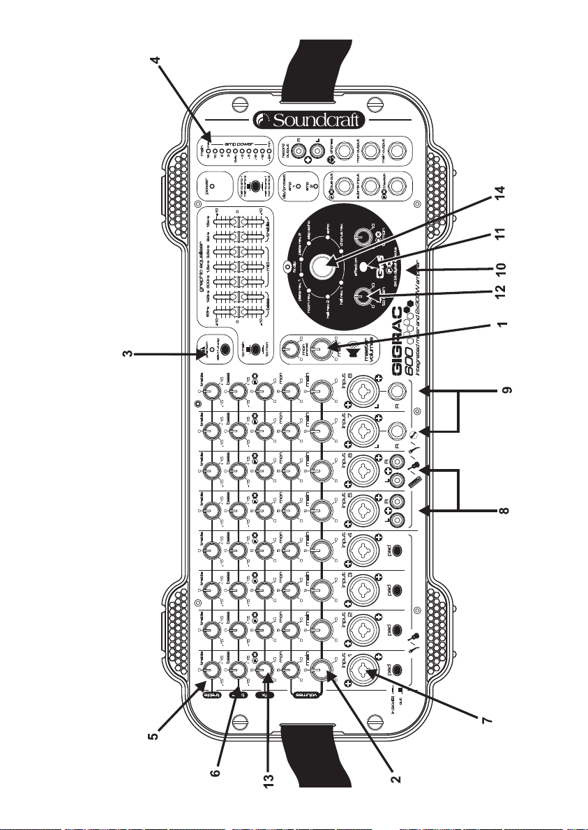
GigRac 600 shown.
9
Page 10

1. Connecting up your loudspeakers to the GigRac
Note: Make sure your GigRac is not powered up. This
is very important to prevent any damage to either the
GigRac or your loudspeakers!
Using good quality speaker cables connect the loudspeakers to the
Speaker outputs on the rear of the GigRac.
If you have cables equipped with Neutrik Speakon connectors then use
the Speakon connectors on the rear of the GigRac. Alternatively if you
have cables equipped with jack plugs then use the jack sockets on the
rear of the GigRac.
Note: Because the GigRac 300 and GigRac 600 are
mono mixers there is no difference between the signals
sent to the Left or Right speakers i.e. both speakers
will receive the same signal equally all of the time.
Make sure that the Main Master V olume control (1) is turned fully down
Now switch the GigRac on using the Power switch on the rear of the
unit.
2. Plugging in a vocal microphone
Note: Before connecting a microphone to channels 1-4,
make sure that the 48V phantom power switch is
switched off (The red LED should not be illuminated)
Connect the microphone cable to one of the first four inputs on the
front of the GigRac.
(The inputs on the GigRac can receive either 3-Pin XLR or standard Jack
connectors.)
10
Page 11
Turn the Main Master Volume control (1) up to about half-way.
Now gradually turn up the Main Volume control (2) on the microphone
channel you have chosen to use. You should now hear the microphone
signal appearing in the loudspeakers as you begin to speak.
You should also be able to see activity on the Output Meter (4)
Note: The XLR input on channels 1 - 4 is very sensitive.
Depending on your microphone or your application, you
may need to press the PAD button to prevent
distortion occurring; don’t worry, this is perfectly
normal.
Note: Be careful not to point the microphone at the
loudspeakers or you could accidentally create
unpleasant feedback sounds.
A note on Condenser Microphones
If your microphone is a condenser microphone that requires phantom
power you will need to switch on the 48V phantom power switch (3)
located to the left of the Graphic Equaliser . Before doing this mak e sure
that the Main Volume control (2) on the chosen channel is turned fully
off to avoid causing an unpleasant sound that might damage your
speakers.
11
Page 12

3. Adding Treble or Bass to the signal
The GigRac offers simple Treble and Bass control for changing the tone
of the signal.
Treble (5)
To add or remove some brightness or ‘sparkle’ to or from a signal, use
the Treble control. In the center ‘click’ position (0) the Treble control
has no effect. Turning it clockwise will boost the treble frequencies
making the signal sound brighter. T urning it anti-clockwise will have the
opposite effect by removing the treble frequencies and making the signal
sound less bright.
The Treble control is handy for adding some sparkle for example to an
acoustic guitar, or for reducing the ‘s’ sound from sibilant vocals.
Bass (6)
To add some ‘bass thump’ to a signal or remove some ‘boominess’ or
rumble, use the Bass control. In the center ‘click’ position (0) the Bass
control has no effect. T urning it clockwise will boost the Bass frequencies
making the signal sound punchier and more ‘bassy’. Turning it anticlockwise will have the opposite effect by removing the bass frequencies
and making the signal sound less ‘boomy’.
The Bass control is useful for making a bass drum sound punchier, or
alternatively could be used for reducing explosive ‘b’ and ‘p’ sounds from
a vocal signal.
12
Page 13

4. Plugging in an Acoustic Guitar, Stereo Keyboard or CD
Player
The GigRac will happily receive signals from instruments with either mono
or stereo outputs such as guitars (Mono) or stereo keyboards and CD
Players (Stereo)
Before plugging in, make sure the Main V olume control (2) for the chosen
channel is turned fully off to avoid accidental damage to your speakers.
Acoustic Guitars
Set the Main Master V olume control (1) to about halfway.
Make sure the Main V olume control (2) on the channel you are about to
use is turned fully down.
Plug the guitar lead into the jack socket in the center of the combination
input socket (7) on the channel of your choice. Turn up the volume
control on your guitar to about halfway, and then gradually turn up the
Main V olume control (2) until you hear the guitar signal appearing in the
loudspeakers.You should also see activiity on the Main Ouptut meter
(4).
Stereo Keyboards and CD Players
The GigRac offers four channels that can receive stereo inputs. T wo of
these channels are equipped with RCA/Phono connectors (Channel 5
and 6) (8) and two with Jack connectors (Channels 7 and 8) (9).
Connect up the Left and Right outputs of your CD player or Cassette
deck to the Left and Right RCA/Phono inputs on either Channel 5 or 6 of
the GigRac. T urn up the Main Master V olume control (1) to about halfway ,
and then turn up the Main Volume control (2) on the chosen channel
until you hear the signal appearing in the loudspeakers.
Connect up the Left and Right outputs of your Stereo Keyboard to the
Left and Right Jack inputs on either Channel 7 or 8 of the GigRac. Set
the volume control of your keyboard to about halfway. Turn up the Main
Master V olume control (1) to about halfway, and then turn up the Main
Volume control (2) on the chosen channel until you hear the signal
appearing in the loudspeakers.
You may now use the Treble and Bass controls as mentioned above to
change the tone of the signals.
13
Page 14

5. Apply one of the 8 GigFX digital effects to the signals
The GigRac’s GIGFX Processor (10) has a choice of 8 studio quality
digital effects that can be added to any individual or group of signals
running through the mixer. Usually vocals require some digital reverb or
echo to be added to them in order to create a more spatial sound that
is pleasing to the listener.
Make sure the ‘FX On’ button is selected
To try this out simply select one of the 8 GigFX presets such as Hall
Reverb using the selector knob (14). Make sure the ‘Bypass’ switch
(11) is not selected.
Turn the ‘FX to Main’ control (12) to about halfway and then gradually
turn up the individual ‘FX’ send control (13) on the channel you wish to
add the effect to. As you turn up the ‘FX’ send level you should hear the
signal change.
By pressing the ‘FX On’ (11) switch to the off position you can compare
the original ‘dry’ signal with the ‘wet’ effected signal.
You can now turn the selector knob (14) to select different types of
effects for comparative purposes
A Note on Channel UseA Note on Channel Use
A Note on Channel Use
A Note on Channel UseA Note on Channel Use
Channels 1-4 are the most sensitive. It is better to use these channels
for microphones (particularly if your microphones are fitted with jack
plugs), and guitars with passive pickups. It is likely that you will need to
have the pad buttons pressed in if you use mics fitted with XLRs.
Channels 5-8 are less sensitive, they are ideal for line-level devices such
as keyboards, CD players and tape players. They will also work with
guitars with active pickups. Microphones fitted with XLRs will also work
(unless they need phantom power).
14
Page 15

FrFr
ont and Rear Panelsont and Rear Panels
Fr
ont and Rear Panels
FrFr
ont and Rear Panelsont and Rear Panels
Front Panel (GigRac 300 and 600)
Input channel
The GigRac has a total of 8 channels. Channels 1-4 are designed to
handle mono microphone or mono line level signals only. Channels 5-8
are designed to handle mono microphone and mono line level signals but
will also accommodate stereo signals as well. (The GigRac 300 and 600
are mono devices and therefore any stereo signals connected will be
automatically summed to mono before being output.)
(1) Input Connector
7
6
5
4
3
1
2
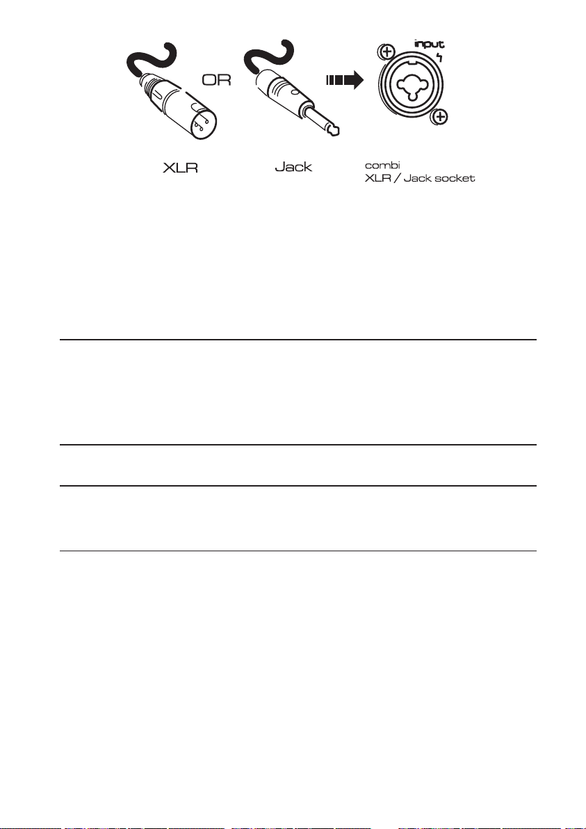
Input Channel
This connector is a combination Jack/3 Pin XLR connector and can receive
any of the following types of input connectors
Microphone cables with Jack connectors
Microphone cables with 3 pin XLR connectors
Line input cables with Jack connectors (e.g. guitars, keyboards
etc.)
Line input cables with 3 pin XLR connectors.
15
Page 16

(2) P(2) P
AD switch (Channels 1-4 only)AD switch (Channels 1-4 only)
(2) P
AD switch (Channels 1-4 only)
(2) P(2) P
AD switch (Channels 1-4 only)AD switch (Channels 1-4 only)
Pressing the P AD switch reduces the input level by 20dB allowing line or
mic level signals that would normally be too loud for the Input stage to
handle to be connected without any audible distortion.
(3) Main V(3) Main V
(3) Main V
(3) Main V(3) Main V
The Main V olume Control determines the amount of level sent from the
channel to the main output mix.
This allows each channel’s relative volume level to be ‘blended’ together
to create the final mix whose overall level is then controlled by the Main
Master V olume control (8) .
(4) Mon V(4) Mon V
(4) Mon V
(4) Mon V(4) Mon V
The Monitor (Mon) V olume Control determines the amount of level sent
from the channel to the Monitor (Mon) Output (20) and also the Phones
Output(18)
This allows each channel’s relative volume level to be ‘blended’ together
to create a separate monitor mix whose overall level is then controlled
by the Mon Master V olume control (9). This feature is used mainly for
creating a ‘foldback’ mix for the musicians and would normally be sent to
a monitor speaker with its own amplifier. (This could also be used for
creating a headphone mix)
The Mon V olume Control operates independent of the Main V olume Control
and will therefore not be affected if the Main Volume Control is turned
up or down. (For the more technically minded, the signal is sourced PreFader and Post EQ)
olume Controlume Contr
olume Contr
olume Controlume Contr
olume Controlume Contr
olume Contr
olume Controlume Contr
olol
ol
olol
olol
ol
olol
(5) FX Control
The FX Control determines the amount of level sent from the channel to
the GigFX digital effects processor and also to the ‘FX Bus output’
connector (21)
This allows each channel’s relative level to be ‘blended’ together to create
a separate effects mix whose overall level is then controlled by the ‘FX
to Main’ (24) and ‘FX to Mon’ (25).
The FX Bus Output connector could also be used to connect to other
external devices such as effects processors or recorders.
16
Page 17

(6) Bass Contr(6) Bass Contr
(6) Bass Contr
(6) Bass Contr(6) Bass Contr
The Bass Control is set at 80Hz and allows you to either add or remove
the low frequency content of the signal by 15dB.
Rotating the control clockwise will ’boost’ the signal, rotating the control
anticlockwise will ‘cut’ the signal.
This control is useful for adding more ‘thump’ to low frequency signals
such as bass guitars and kick drums but can also be used to remove
unwanted rumble or boominess from signals such as vocal or instrument
microphones.
(7) T(7) T
rr
(7) T
(7) T(7) T
The Treble Control is set at 12kHz and allows you to either add or remove
the high frequency content of the signal by 15dB.
Rotating the control clockwise will ‘boost’ the signal, rotating the control
anticlockwise will ‘cut’ the signal.
This control is useful for adding ‘crispness’ or ‘sizzle’ to signals with a lot
of high frequency content such as guitars and cymbals but can also be
used to remove unwanted sibilance from signals such as vocals.
eble Contreble Contr
r
eble Contr
rr
eble Contreble Contr
olol
ol
olol
olol
ol
olol
17
Page 18

Master Section GigRac 600Master Section GigRac 600
Master Section GigRac 600
Master Section GigRac 600Master Section GigRac 600
18
Page 19

(8) Main Master Volume Control
This control determines the overall level that is sent to the internal
amplification and to the Main Output socket.(19)
(9) Mon (PHONES) Master Volume Control
This control determines the overall level that is sent to the Monitor
Output (Mon Output) and Phones socket.
(10) Phantom 48V switch
This switch turns the 48v phantom power On/Off for the 3 pin XLR
sockets on channels 1-4. When the switch is turned On the red LED
will illuminate.
48V phantom power is used to power condenser microphones and DI
boxes.
NB! To avoid possible damage to your loudspeakers,
make sure that the Main and Monitor Master Volume
controls are turned down fully before switching on the
48V phantom power.
(11) Graphic Equaliser
The Graphic Equaliser is divided into 7 frequency bands. Each frequency
band can be used to either ‘cut’ or ‘boost’ the Main Output signal by up
to 10dB.
The Graphic Equaliser is very useful for compensating for poor room
acoustics or improving the performance of your loudspeakers.
(12) To Main/To Mon switch (GigRac 600 only)
This switch determines which signal path is sent to the Graphic Equaliser .
Normally the Graphic Equaliser operates on the Main Mix output path
(To Main) but it might be desirable for some applications to have the
Graphic Equaliser assigned to the Mon Mix output path.
19
Page 20

(13) Power LED
The red Power LED illuminates when the GigRac is switched on.
(14) Main to Amp 1/Mon to Amp 2 - Main to Amp 1/Main to
Amp 2 switch (GigRac 600 only)
This switch determines which signals are sent to Amp 1/Speaker Output
1 and Amp 2/Speaker Output 2.
The Choices are:
Main to Amp 1/Main to Amp 2 – The Main Mix is sent to both Speaker
Output 1 and Speaker Output 2.
Main to Amp 1/Mon to Amp 2 – The Main Mix Output will appear on
Speaker Output 1 and the mon Mix Output will appear on Speak er Output
2
20
Page 21

21
Page 22

(15) Amp Clip LED
The red Amp Clip LED illuminates when the input level to the internal
amplifier is too high. It is acceptable for this LED to come on momentarily
every now and then but the Main or Monitor Master V olume (depending
on which mode has been selected: see (14) above) should be turned
down if the Amp Clip LED illuminates consistently .
NB! Continued use of the GigRac with the Amp Clip
LED illuminated could cause serious damage to your
GigRac and your loudspeakers!
(16) Main Output meter
The 10-segment output meter shows the signal level output from the
Main Master V olume control.
It is best to aim to have the red 10dB LED lighting up regularly during
the loudest signals peaks playing through your GigRac and the 16dB
LED flicking on very occasionally. This will ensure that a good level is
passing through the mixer.
(17) Record Output
The Record Output is for connecting a recording device such as a
cassette or mini disk recorder.
The signal output at the Record Output socket is a post fade signal
derived from the Main Mix output. The amount of signal level leaving the
GigRac via the Record Outputs is determined by the Main Master Volume
control. (8)
(18) Phones Output
Connect headphones to the Phones Output. The Phones Output derives
its signal from the Monitor (Mon) controls on each channel and the over
all volume of the headphones output is determined by using the Mon
(Phones) Master V olume control (9)
(19) Main Output
The Main Output carries the Main Mix signal after it has passed through
the Graphic Equaliser and the Main Master Volume control (i.e. the
same signal that is sent to the internal amplification). This output can
22
Page 23

be used to send the Main Mix to another amplifier or powered speaker
or alternatively it can be used to send a ‘submix’ to another mixer’s
input channel or another recording device.
(20) Mon Output
The Mon Output carries the Monitor Mix signal derived from the Mon
controls on each channel. The Mon output level is controlled by the Mon
Master V olume control.(9)
This output is used mainly to send the Mon Mix signal to an on stage fold
back speaker system of some kind.
(21) FX Bus Output
The FX Bus Output carries the FX Mix signal as derived from the FX
controls on each channel. This allows additional external effects
processing devices to be used in conjunction with the GigRac’s built in
GigFX digital effects processor.
(22) Submix Input
The Submix Input allows the output from another mixer to be blended
with the Main Mix Output of the GigRac. This input could also be used
for connecting an effects return signal from an external effects
processing device.
(23) FX Bypass Footswitch
The FX Bypass Footswitch sock et is used for connecting an optional foot
switch to turn the GigFX processor On and Off.
(24) Effect on switch
The effect on switch has a toggle action, the adjacent LED indicates
when the FX unit is on.
23
Page 24

Master Section GigRac 300Master Section GigRac 300
Master Section GigRac 300
Master Section GigRac 300Master Section GigRac 300
(8) Main Master Volume Control
This control determines the overall level that is sent to the internal
amplification and to the Main Output socket.
(9) Monitor Master Volume Control (Mon Master Volume Control)
This control determines the overall level that is sent to the Monitor
Output (Mon Output) and Phones socket.
24
Page 25

(10) Phantom 48V switch
This switch turns the 48v phantom power On/Off for the 3 pin XLR
sockets on channels 1-4. When the switch is turned On the red LED
will illuminate.
48V phantom power is used to power condenser microphones and DI
boxes.
NB! To avoid the possible damage to your loudspeakers,
make sure that the Main and Monitor Master Volume
controls are turned downfully before switching on the
48V phantom power.
(11) Graphic Equaliser(11) Graphic Equaliser
(11) Graphic Equaliser
(11) Graphic Equaliser(11) Graphic Equaliser
The Graphic Equaliser is divided into 7 frequency bands. Each frequency
band can be used to either ‘cut’ or ‘boost’ the Main Output signal by up
to 10dB.
The Graphic Equaliser is very useful for compensating for poor room
acoustics or improving the performance of your loudspeakers.
(12) Main To Amp/Mon To Amp switch
This switch is usually set to ‘Main To Amp’ (Up position), which means
that the output from the Main Master V olume (8) is sent to the internal
amplification and then out of the Speaker Outputs on the rear of the
GigRac.
Alternatively it is possible by pressing the switch down, to send the
output from the Mon Master Volume (9) to the internal amplification
and then out of the Speaker Outputs.
When the ‘Mon to Amp’ mode is selected the Main Output is not sent to
the Speaker 1 and Speak er 2 outputs but is available at the Main output
Jack socket (18)
(13) Power LED
The red Power LED illuminates when the GigRac is switched on.
25
Page 26

(14) Amp Clip LED
The red Amp Clip LED illuminates when the input level to the internal
amplifier is too high. It is acceptable for this LED to come on momentarily
every now and then but the Main or Monitor Master V olume (depending
on which mode has been selected – see (12) above) should be turned
down if the Amp Clip LED illuminates consistently .
NB! Continued use of the GigRac with the Amp Clip
LED illuminated could cause serious damage to your
GigRac and your loudspeakers!
(15) Main Output meter
The 10-segment output meter shows the signal level output from the
Main Master V olume control. (8)
It is best to aim to have the red 10dB LED lighting up regularly during
the loudest signals peaks playing through your GigRac and the 16dB
LED flicking on very occasionally. This will ensure that a good level is
passing through the mixer.
(16) Record Output
The Record Output is for connecting a recording device such as a
cassette or mini disk recorder.
The signal output at the Record Output socket is a post fade signal
derived from the Main Mix output. The amount of signal level leaving the
GigRac via the Record Outputs is determined by the Main Master Volume
control.(8)
(17) Phones Output
Connect headphones to the Phones Output. The Phones Output derives
its signal from the Monitor (Mon) controls on each channel and the over
all volume of the headphones output is determined by using the Mon
(Phones) Master V olume control (9)
(18) Main Output
The Main Output carries the Main Mix signal after it has passed through
the Graphic Equaliser and the Main Master Volume control (i.e. the
same signal that is sent to the internal amplification). This output can
26
Page 27

be used to send the Main Mix to another amplifier or powered speaker
or alternatively it can be used to send a ‘submix’ to another mixer’s
input channel or another recording device.
(19) Mon Output
The Mon Output carries the Monitor Mix signal derived from the Mon
controls on each channel. The Mon output level is controlled by the Mon
Master V olume control.(9)
This output is used mainly to send the Mon Mix signal to an on stage fold
back speaker system of some kind.
(20) FX Bus Output
The FX Bus Output carries the FX Mix signal as derived from the FX
controls on each channel. This allows additional external effects
processing devices to be used in conjunction with the GigRac’s built in
GigFX digital effects processor.
(21) Submix Input
The Submix Input allows the output from another mixer to be blended
with the Main Mix Output of the GigRac.
This input could also be used for connecting an effects return signal
from an external effects processing device.
(22) FX Bypass Footswitch
The FX Bypass Footswitch socket is used for connecting an optional
foot switch to turn the GigFX processor On and Off .
(23) Effect On Switch
The effect on switch has a toggle action, the adjacent LED indicates
when the FX unit is on.
27
Page 28

Rear Panel GigRac 600Rear Panel GigRac 600
Rear Panel GigRac 600
Rear Panel GigRac 600Rear Panel GigRac 600
(1) Power Switch
This switch turns the GigRac On or Off. The red P ower LED (13) on the
front panel will illuminate to confirm this.
NB! Before switching the GigRac On or Off, make sure
that the Main and Mon Master Volume controls are
turned fully down.
(2) Power Socket
Connect the supplied power cable to this socket.
(3) Speakers Outputs (Amp 1 and Amp 2)
The Speaker Outputs are available as Neutrik Speakon connectors and
standard ¼” Jack connectors.
Connect your loudspeakers to these outputs. The signal sent to the
Speakon connectors and the Jack sockets is e xactly the same.
Use the appropriate connector type to match the input connectors on
your loudspeakers. The GigRac 600 is designed to work with loudspeakers
rated at either 8 ohms or 4 ohms.
The minimum load that either of the amplifiers inside the GigRac 600
should be presented with is 4 ohms. this means that a single 4 or 8 ohm
speaker can be connected to each amplifier outputs as shown in Fig 1.
Alternatively, two 8 ohm speakers can be connected in parallel to each
amplifier output, as shown in Fig 2. Two speakers connected like this
gives a combined load of 4 ohms.
28
Page 29

29
Page 30

Rear Panel GigRac 300Rear Panel GigRac 300
Rear Panel GigRac 300
Rear Panel GigRac 300Rear Panel GigRac 300
(1) Power Switch
This switch turns the GigRac On or Off. The red P ower LED (13) on the
front panel will illuminate to confirm this.
NB! Before switching the GigRac On or Off, make sure
that the Main and Mon Master Volume controls are
turned fully down.
(2) Power Socket
Connect the supplied power cable to this socket.
(3) Speakers Outputs
The Speaker Outputs are available as Neutrik Speakon connectors and
standard ¼” Jack connectors.
Connect your loudspeakers to these outputs. The signal sent to the
Speakon connectors and the Jack sockets is e xactly the same.
Use the appropriate connector type to match the input connectors on
your loudspeakers.
The minimum load that the amplifier inside the GigRac should be presented
with is 4 ohms. This means that a single 8 ohm speaker can be connected
to each of the speaker outputs as shown in Fig1, or two 8 ohm speak ers
can be connected in parallel to one of the speaker outputs as shown in
Fig 2. Two speakers connected like this gives a combined load of 4
ohms.
30
Page 31

31
Page 32

Rackmounting YRackmounting Y
Rackmounting Y
Rackmounting YRackmounting Y
The GigRac 300 or 600 can be rack mounted into a standard 19’’rack.This
is useful for fixed instalations or for applications where the GigRac might
need to be installed into a portable 19’’ rack along with other equipment.
our GigRacour GigRac
our GigRac
our GigRacour GigRac
32
Page 33

Connectors and LeadsConnectors and Leads
Connectors and Leads
Connectors and LeadsConnectors and Leads
33
Page 34

Block Diagram GigRac 600Block Diagram GigRac 600
Block Diagram GigRac 600
Block Diagram GigRac 600Block Diagram GigRac 600
34
Page 35

Block Diagram GigRac 300Block Diagram GigRac 300
Block Diagram GigRac 300
Block Diagram GigRac 300Block Diagram GigRac 300
35
Page 36

WW
arar
rantyranty
W
ar
ranty
WW
arar
rantyranty
1 Soundcraft is a trading division of Harman International Industries Ltd .
End User means the person who first puts the equipment into regular
operation.
Dealer means the person other than Soundcraft (if any) from whom the
End User purchased the Equipment, provided such a person is authorised for this purpose by Soundcraft or its accredited Distributor.
Equipment means the equipment supplied with this manual.
2 If within the period of twelve months from the date of delivery of the
Equipment to†the End User it shall prove defective by reason only of
faulty materials and/or workmanship to such an extent that the effectiveness and/or usability thereof is materially affected the Equipment or
the defective component should be returned to the Dealer or to
Soundcraft and subject to the following conditions the Dealer or
Soundcraft will repair or replace the defective components. Any components replaced will become the property of Soundcraft.
3 Any Equipment or component returned will be at the risk of the End
User whilst in transit (both to and from the Dealer or Soundcraft) and
postage must be prepaid.
4 This warranty shall only be valid if:
a) the Equipment has been properly installed in accordance with
instructions contained in Soundcraftís manual; and
b) the End User has notified Soundcraft or the Dealer within 14
days of the defect appearing; and
c) no persons other than authorised representatives of Soundcraft
or the Dealer have effected any replacement of parts maintenance
adjustments or repairs to the Equipment; and
d) the End User has used the Equipment only for such purposes as
Soundcraft recommends, with only such operating supplies as meet
Soundcraftís specifications and otherwise in all respects in accordance
with Soundcraftís recommendations.
5 Defects arising as a result of the following are not covered by this
Warranty : faulty or negligent handling, chemical or electro-chemical or
electrical influences, accidental damage, Acts of God, neglect, defi-
ciency in electrical power, air-conditioning or humidity control.
6 The benefit of this Warranty may not be assigned by the End User.
7 End Users who are consumers should note their rights under this
Warranty are in addition to and do not affect any other rights to which
they may be entitled against the seller of the Equipment.
36
Page 37

Gigrac 300 / 600 SpecificationsGigrac 300 / 600 Specifications
Gigrac 300 / 600 Specifications
Gigrac 300 / 600 SpecificationsGigrac 300 / 600 Specifications
Noise
EIN 150 ohms 20 - 22kHz CH1 - CH4 -123 dBu
EIN 150 ohms 20 - 22kHz CH5 - CH6 -123 dBu
Main out Level control mid -78 dBu
Mon out Level control mid -80 dBu
Amp out -57 dBu
Crosstalk
Main cutoff -80 dB
Mon cutoff -80 dB
Frequency Response
20 - 22Khz rel 1kHz Line in to Main out +0.2/-2.5 dB
THD+N
Mic i/p -20dB Pad 0dBu I/P at Main out (22Hz-22kHz) 0.15 %
Mic i/p to Amp Out @ full power 22-22kHz 0.15%
INPUTS
Mic Input Impedance 5.5 kohms
Line Input Impedance 30 kohms
Max Input Mic (20dB pad ) -3.5 dBu
Max Input Line (20dB pad ) 10 dBu
Max Mic gain to main out 60 dB
INPUTS CH5 CH8
Mic Input Impedance 2.4 kohms
Line Input Impedance 40 kohms
Max Input Mic -18 dBu
Max Input Line 3 dBu
Max Mic gain to main out 50 dB
OUTPUTS
Max out main / mon 18dBu
Power Output Gigrac 300: 300W into 4 ohms
Power Output Gigrac 600: 2 X 300W into
4 ohms
CONNECTORS
(All Jacks are 3 pole 1/4")
Mic: Balanced XLR combi connectors/ Balanced jack combi connectors
Line: Balanced Jack / combi connectors / Unbalanced RCA phono
FX bus output: Impedance Balanced Jack
Submix in: Unbalanced Jack
Main out: Impedance Balanced Jack
Mon out: Impedance Balanced Jack
Record out: unbalanced RCA phono
Phones: Jack
Speakers: Speakon (pins +1 and -1) and Jack
37
Page 38

YY
our Notes:our Notes:
Y
our Notes:
YY
our Notes:our Notes:
38
Page 39

39
Page 40

Soundcraft
Harman International Industries Ltd
Cranborne House, Cranborne Road, Potters Bar, Herts, EN6 3JN, UK
TEL: +44 (0)1707 665000 FAX: +44 (0)1707 660742 EMAIL: info@soundcraft.com
Soundcraft USA
8500 Balboa Blvd., Northridge, CA 91329, USA
TEL: +1-818-920-3212 FAX: +1-818-920-3208 EMAIL: soundcraft-usa@harman.com
www.gigrac.com
Soundcraft reserves the right to improve or otherwise alter any information supplied in this document or any other documentation supplied hereafter.E&OE 11/03.
This equipment complies with the EMC Directive 89/336/EEC
 Loading...