

Page 1

Safety Symbol GuideSafety Symbol Guide
Safety Symbol Guide
Safety Symbol GuideSafety Symbol Guide
ApprAppr
ovals and Noticeovals and Notice
Appr
ovals and Notice
ApprAppr
ovals and Noticeovals and Notice
WW
arar
rantyranty
W
ar
ranty
WW
arar
rantyranty
ImporImpor
Impor
ImporImpor
CautionsCautions
Cautions
CautionsCautions
WW
W
WW
tant Safety Instrtant Safety Instr
tant Safety Instr
tant Safety Instrtant Safety Instr
arar
ningsnings
ar
nings
arar
ningsnings
uctionsuctions
uctions
uctionsuctions
SAFETY GUIDESAFETY GUIDE
SAFETY GUIDE
SAFETY GUIDESAFETY GUIDE
PagePage
Page
PagePage
22
2
22
33
3
33
44
4
44
55
5
55
55
5
55
66
6
66
1
Page 2

USER GUIDEUSER GUIDE
USER GUIDE
USER GUIDEUSER GUIDE
Safety Symbol GuideSafety Symbol Guide
Safety Symbol Guide
Safety Symbol GuideSafety Symbol Guide
For your own safety and to avoid invalidation of the warranty all text marked with
these symbols should be read carefully.
CAUTIONS
Must be followed carefully to avoid bodily injury.
WARNINGS
Must be observed to avoid damage to your
equipment.
NOTES
Contain important information and useful tips on
the operation of your equipment.
2
Page 3
IMPORTANT
Please read this manual carefully before
connecting your mixer to the mains for the first
time.
© Harman International Industries Ltd. 2002
All rights reserved
Parts of the design of this product may be protected by worldwide patents.
Part No. ZM0261
Issue:4
Soundcraft is a trading division of Harman International Industries Ltd. Information
in this manual is subject to change without notice and does not represent a commitment on the part of the vendor. Soundcraft shall not be liable for any loss or
damage whatsoever arising from the use of information or any error contained in
this manual.
No part of this manual may be reproduced, stored in a retrieval system, or transmitted, in any form or by any means, electronic, electrical, mechanical, optical, chemical, including photocopying and recording, for any purpose without the express
written permission of Soundcraft.
Harman International Industries Limited
Cranborne House
Cranborne Road
POTTERS BAR
Hertfordshire
EN6 3JN
UK
Tel: +44 (0)1707 665000
Fax: +44 (0)1707 660742
http://www.soundcraft.com
3
Page 4

USER GUIDEUSER GUIDE
USER GUIDE
USER GUIDEUSER GUIDE
WW
arar
rantyranty
W
ar
ranty
WW
arar
rantyranty
1 Soundcraft is a trading division of Harman International Industries Ltd .
End User means the person who first puts the equipment into regular operation.
Dealer means the person other than Soundcraft (if any) from whom the End User
purchased the Equipment, provided such a person is authorised for this purpose by
Soundcraft or its accredited Distributor.
Equipment means the equipment supplied with this manual.
2 If within the period of twelve months from the date of delivery of the Equipment
to the End User it shall prove defective by reason only of faulty materials and/or
workmanship to such an extent that the effectiveness and/or usability thereof is
materially affected the Equipment or the defective component should be returned to
the Dealer or to Soundcraft and subject to the following conditions the Dealer or
Soundcraft will repair or replace the defective components. Any components
replaced will become the property of Soundcraft.
3 Any Equipment or component returned will be at the risk of the End User whilst in
transit (both to and from the Dealer or Soundcraft) and postage must be prepaid.
4 This warranty shall only be valid if:
a) the Equipment has been properly installed in accordance with instructions
contained in Soundcraft’s manual; and
b) the End User has notified Soundcraft or the Dealer within 14 days of the
defect appearing; and
c) no persons other than authorised representatives of Soundcraft or the Dealer
have effected any replacement of parts maintenance adjustments or repairs
to the Equipment; and
d) the End User has used the Equipment only for such purposes as Soundcraft
recommends, with only such operating supplies as meet Soundcraft’s
specifications and otherwise in all respects in accordance with Soundcraft’s
recommendations.
5 Defects arising as a result of the following are not covered by this Warranty: faulty or
negligent handling, chemical or electro-chemical or electrical influences, accidental
damage, Acts of God, neglect, deficiency in electrical power, air-conditioning or
humidity control.
6 The benefit of this Warranty may not be assigned by the End User.
7 End Users who are consumers should note their rights under this Warranty are in
addition to and do not affect any other rights to which they may be entitled against
the seller of the Equipment.
4
Page 5

IMPORIMPOR
IMPOR
IMPORIMPOR
TT
ANT SAFETY INSTRUCTIONSANT SAFETY INSTRUCTIONS
T
ANT SAFETY INSTRUCTIONS
TT
ANT SAFETY INSTRUCTIONSANT SAFETY INSTRUCTIONS
CAUTIONS
• To avoid the risk of fire, replace the mains fuse only with the correct type and value
fuse, as marked on the bottom of the product.
• ATTENTION: - Afin de réduire le risque de feu remplacer seulement avec fusible de
même type.
• MAINS VOLTAGE SELECTION
This setting is NOT User Adjustable.
The units are capable of operating at either 230V AC or 115V AC mains voltages ±10%.
• REPLACING MAINS FUSE
Remove the mains lead from the connector. Use a small screwdriver to unscrew the
fuse carrier from its location to the left of the mains power connector. Check the fuse is
of the correct type and value and replace if necessary; also check that the voltage
selection as marked on the rear panel is correct for the mains supply level before
switching the unit ON again.
If the mains fuse fails repeatedly this may be because an electrical safety hazard
exists. The unit must be taken out of service and referred to the Soundcraft dealer from
where the equipment was purchased.
• THIS UNIT MUST BE EARTHED
Under no circumstances should the mains earth be disconnected from the mains lead.
• ATTENTION: - Cet appareil doit être branché à la terre.
The wires in the mains lead are coloured in accordance with the following code:
Replacement Part No: FJ8016 (UK) : FJ8017 (EU) : FJ8018 (US & CAN)
UK & EU US & CAN
Earth / Ground: Green and Yellow Green and Yellow
Neutral: Blue White
Live: Brown Black
As the colours of the wires in the mains lead may not correspond with the coloured
markings identifying the terminals in your plug, proceed as follows:
The wire which is coloured Green and Yellow must be connected to the terminal in the
plug which is marked with the letter E or by the earth / ground symbol:
The wire which is coloured Blue or White must be connected to the terminal in the plug
which is marked with the letter N.
The wire which is coloured Brown or Black must be connected to the terminal in the
plug which is marked with the letter L.
Ensure that these colour codings are followed carefully in the event of the plug being
changed.
• Do not install near any heat sources such as radiators, heat resistors, stoves, or other
apparatus (including amplifiers) that produce heat.
5
Page 6

USER GUIDEUSER GUIDE
USER GUIDE
USER GUIDEUSER GUIDE
• Do not use this apparatus near water. The apparatus must not be exposed to dripping
or splashing. Objects containing liquid must not be placed on the apparatus.
• The disconnect device is the mains plug or the appliance connector: either one must
remain accessible so as to be readily operable in use.
• Do not defeat the safety purpose of the polarized or grounding type plug.
A polarized plug has two blades with one wider than the other. A grounding type plug
has two blades and a third grounding prong. The wide blade or the third prong are
provided for your safety. When the provided plug doesnot fit into your outlet, consult
an electrician for replacement of the obsolete outlet.
• Protect the power cord from being walked on or pinched particularly at plugs, conven-
ience receptacles and the point where they exit from the apparatus.
• Only use cables and hardware specified by the manufacturer.
• Unplug this apparatus during lightning storms or when unused for long periods of time.
• Refer all servicing to qualified service personnel. Servicing is required when the appa-
ratus has been damaged in any way such as power-supply cord or plug is damaged.,
liquid has been spilled or objects have fallen into the apparatus, the apparatus has
been exposed to rain or moisture, does not operate normally or has been dropped.
• It is recommended that all maintenance and service on the product should be carried
out by Soundcraft or its authorised agents. Soundcraft cannot accept any liability whatsoever for any loss or damage caused by service, maintenance or repair by unauthorised personnel.
• If a trolley is used, use caution when moving the trolley / apparatus combination to
avoid injury from tip-over.
WARNINGS
• Read these instructions.
• Keep these instructions.
• Heed all warnings.
• Follow all instructions.
• This unit contains no user serviceable parts. Refer all servicing to a qualified service
engineer, through the appropriate Soundcraft dealer.
• Clean the apparatus only with a dry cloth.
• DO NOT block any of the ventilation openings. DO NOT install where air cannot flow over
the rear of the unit. DO Install in accordance with the manufacturers instructions.
6
Page 7

CONTENTSCONTENTS
CONTENTS
CONTENTSCONTENTS
OverOver
viewview
Over
view
OverOver
viewview
The 10 Second TThe 10 Second T
The 10 Second T
The 10 Second TThe 10 Second T
IntrIntr
oductionoduction
Intr
oduction
IntrIntr
oductionoduction
Advice for Those Who Push the BoundariesAdvice for Those Who Push the Boundaries
Advice for Those Who Push the Boundaries
Advice for Those Who Push the BoundariesAdvice for Those Who Push the Boundaries
Installation & Safety PrInstallation & Safety Pr
Installation & Safety Pr
Installation & Safety PrInstallation & Safety Pr
Wiring UpWiring Up
Wiring Up
Wiring UpWiring Up
Mono Input ChannelsMono Input Channels
Mono Input Channels
Mono Input ChannelsMono Input Channels
SterSter
eo Input Channelseo Input Channels
Ster
eo Input Channels
SterSter
eo Input Channelseo Input Channels
Master SectionMaster Section
Master Section
Master SectionMaster Section
Using YUsing Y
Using Y
Using YUsing Y
Fitting Rackmount EarsFitting Rackmount Ears
Fitting Rackmount Ears
Fitting Rackmount EarsFitting Rackmount Ears
Application 1 Live Sound ReinforApplication 1 Live Sound Reinfor
Application 1 Live Sound Reinfor
Application 1 Live Sound ReinforApplication 1 Live Sound Reinfor
Application 2 Multispeaker ApplicationsApplication 2 Multispeaker Applications
Application 2 Multispeaker Applications
Application 2 Multispeaker ApplicationsApplication 2 Multispeaker Applications
Application 3 Places of WApplication 3 Places of W
Application 3 Places of W
Application 3 Places of WApplication 3 Places of W
Application 4 RecorApplication 4 Recor
Application 4 Recor
Application 4 RecorApplication 4 Recor
Application 5 Linking Two Spirit E Series ConsolesApplication 5 Linking Two Spirit E Series Consoles
Application 5 Linking Two Spirit E Series Consoles
Application 5 Linking Two Spirit E Series ConsolesApplication 5 Linking Two Spirit E Series Consoles
GlossarGlossar
Glossar
GlossarGlossar
Typical SpecificationsTypical Specifications
Typical Specifications
Typical SpecificationsTypical Specifications
DimensionsDimensions
Dimensions
DimensionsDimensions
Typical Connecting LeadsTypical Connecting Leads
Typical Connecting Leads
Typical Connecting LeadsTypical Connecting Leads
System Block DiagramSystem Block Diagram
System Block Diagram
System Block DiagramSystem Block Diagram
ContrContr
Contr
ContrContr
our Spirit E Series Consoleour Spirit E Series Console
our Spirit E Series Console
our Spirit E Series Consoleour Spirit E Series Console
yy
y
yy
ol Position Markup Sheetsol Position Markup Sheets
ol Position Markup Sheets
ol Position Markup Sheetsol Position Markup Sheets
utorutor
utor
utorutor
ecautionsecautions
ecautions
ecautionsecautions
dingding
ding
dingding
orshiporship
orship
orshiporship
cementcement
cement
cementcement
PagePage
Page
PagePage
1010
10
1010
1010
10
1010
1111
11
1111
1212
12
1212
1616
16
1616
1919
19
1919
2121
21
2121
2323
23
2323
2525
25
2525
2626
26
2626
2727
27
2727
2727
27
2727
2828
28
2828
2828
28
2828
2929
29
2929
3131
31
3131
3333
33
3333
3636
36
3636
3838
38
3838
3939
39
3939
88
8
88
99
9
99
7
Page 8

USER GUIDEUSER GUIDE
USER GUIDE
USER GUIDEUSER GUIDE
1
2
3
4
5
6
7
OverOver
Over
OverOver
viewview
view
viewview
woar
e
s
f
h
g
i
u
p
y
9
8
0
d
t
q
To get you working as fast as possible, this manual begins with a 10 second tutorial. Here you can find quick information on any feature
of the console, and a page reference where you can find a more detailed explanation.
8
Page 9

THE 10 SECOND TUTORTHE 10 SECOND TUTOR
THE 10 SECOND TUTOR
THE 10 SECOND TUTORTHE 10 SECOND TUTOR
MIC INPUT (XLR)MIC INPUT (XLR)
1
MIC INPUT (XLR) Connect Microphones here. If you are using a condenser mic, ensure phantom power
MIC INPUT (XLR)MIC INPUT (XLR)
is supplied by pressing the switch at the top of the master section
WARNING:WARNING:
WARNING: Do Not apply Phantom Power before connecting a microphone
WARNING:WARNING:
LINE INPUT (LINE INPUT (
2
LINE INPUT (¼
LINE INPUT (LINE INPUT (
INSERT POINT (INSERT POINT (
3
INSERT POINT (¼
INSERT POINT (INSERT POINT (
GAIN CONTROLGAIN CONTROL
4
GAIN CONTROL Adjust this to increase or decrease the level of the incoming signal
GAIN CONTROLGAIN CONTROL
EQ STAGEEQ STAGE
5
EQ STAGE Adjust these controls to change the signal tone (the character of the signal)
EQ STAGEEQ STAGE
AUX SENDSAUX SENDS
6
AUX SENDS Adjust these controls to change the level of the signal to an FX unit or an artist’s
AUX SENDSAUX SENDS
PAN CONTROLPAN CONTROL
7
PAN CONTROL Use this control to position the signal within the stereo field
PAN CONTROLPAN CONTROL
MUTE SWITCHMUTE SWITCH
8
MUTE SWITCH When this is pressed you will hear no signal from the channel (post-mute signals)
MUTE SWITCHMUTE SWITCH
SOLOSOLO
9
SOLO When pressed the signal will appear on the monitor outputs - use this to monitor the
SOLOSOLO
PEAK LEDPEAK LED
0
PEAK LED This is used to indicate that the signal close to distorting (clipping) on a specific
PEAK LEDPEAK LED
INPUT CHANNEL FADERINPUT CHANNEL FADER
q
INPUT CHANNEL FADER This is used to control the level fed to the Mix Bus and post-fade sends
INPUT CHANNEL FADERINPUT CHANNEL FADER
MIX OUTPUTS (XLR)MIX OUTPUTS (XLR)
w
MIX OUTPUTS (XLR) Connect these to your analogue recording device, or to your amplification system
MIX OUTPUTS (XLR)MIX OUTPUTS (XLR)
MIX INSERTS (MIX INSERTS (
e
MIX INSERTS (¼
MIX INSERTS (MIX INSERTS (
MONITOR O/Ps (MONITOR O/Ps (
r
MONITOR O/Ps (¼
MONITOR O/Ps (MONITOR O/Ps (
MASTER FADERSMASTER FADERS
t
MASTER FADERS These faders control the overall level of the mix bus
MASTER FADERSMASTER FADERS
MAIN METERSMAIN METERS
y
MAIN METERS These show the level of the mix outputs. When the SOLO LED is lit, the meters show
MAIN METERSMAIN METERS
MONITOR CONTROLMONITOR CONTROL
u
MONITOR CONTROL This controls the level of the signal sent to your monitoring system
MONITOR CONTROLMONITOR CONTROL
PHONES CONTROLPHONES CONTROL
i
PHONES CONTROL This controls the level of the signal sent to the headphones jack socket
PHONES CONTROLPHONES CONTROL
AUX OUTPUTS (AUX OUTPUTS (
o
AUX OUTPUTS (¼
AUX OUTPUTS (AUX OUTPUTS (
AUX CONTROLSAUX CONTROLS
p
AUX CONTROLS These two switches globally switch the AUX1 and AUX2 feeds respectively, on all the
AUX CONTROLSAUX CONTROLS
STEREO INPUTS (STEREO INPUTS (
a
STEREO INPUTS (¼
STEREO INPUTS (STEREO INPUTS (
PLAYBACK INPUTS (RCA Phono)PLAYBACK INPUTS (RCA Phono)
s
PLAYBACK INPUTS (RCA Phono) Here you can connect the playback from your recording device
PLAYBACK INPUTS (RCA Phono)PLAYBACK INPUTS (RCA Phono)
PLAYBACK CONTROLSPLAYBACK CONTROLS
d
PLAYBACK CONTROLS Use these to control the playback signal. The MONITOR PLAYBACK switch sends the
PLAYBACK CONTROLSPLAYBACK CONTROLS
RECORD OUTPUTSRECORD OUTPUTS
f
RECORD OUTPUTS Here you can connect the input to your recording device
RECORD OUTPUTSRECORD OUTPUTS
PHANTOM POWERPHANTOM POWER
g
PHANTOM POWER Press this to switch the phantom power (48V) on for condenser microphones
PHANTOM POWERPHANTOM POWER
HEADPHONES (HEADPHONES (
h
HEADPHONES (¼
HEADPHONES (HEADPHONES (
” Jack)” Jack)
” Jack) Connect Line level sources here, e.g. Synth, Drum Machine, DI etc
” Jack)” Jack)
” Jack)” Jack)
” Jack) Connect Signal processors here, e.g. Compressor, Gate etc
” Jack)” Jack)
monitors (headphones/in-ear/stage monitors). Aux 1&2 are switchable pre/post
fade
post EQ signal from the channel
channel
” Jack)” Jack)
” Jack) This is a pre-fade break in the signal path which can be used to feed a dynamics or
” Jack)” Jack)
mastering device. The signal is sent from the tip of the jack plug and the return path
comes back in on the ring of the jack plug
” Jack)” Jack)
” Jack) These are used to feed your monitoring system. This can be directly connected to
” Jack)” Jack)
powered monitors, or indirectly via an amplifier to standard monitors
the level of the signal sourced
” Jack)” Jack)
” Jack) These two outputs can be used to send the channel signal to an FX unit or an artist’s
” Jack)” Jack)
monitors (headphones/in-ear/stage monitors). Aux 1&2 are switchable pre/post
fade
input modules to be either pre or post-fade
” Jack)” Jack)
” Jack) These two inputs can be used to connect line level stereo inputs from keyboards,
” Jack)” Jack)
sound modules, samplers, computer based audio cards etc. These inputs pass
through a normal channel strip, with EQ, Auxes and a Balance control
signal to the monitor outputs and phones, whilst the PLAYBACK TO MIX switch sends it
to the main mix
WARNING:WARNING:
WARNING: Do Not apply Phantom Power before connecting a microphone
WARNING:WARNING:
” Jack)” Jack)
” Jack) Plug your headphones into this socket
” Jack)” Jack)
g
9
Page 10

USER GUIDEUSER GUIDE
USER GUIDE
USER GUIDEUSER GUIDE
INTRODUCTIONINTRODUCTION
INTRODUCTION
INTRODUCTIONINTRODUCTION
Thank you for purchasing a Soundcraft mixer. We take great pride in our latest addition to the
Spirit range of mixing consoles - you have taken a step in the right direction and should never
look back.
The packaging which your Spirit E Series arrived in, forms part of the product and must be
retained for future use.
Owning a Soundcraft console brings you the expertise and support of one of the industry’s
leading manufacturers, and the results of nearly 3 decades of supporting some of the biggest
names in the business. Our knowledge has been attained through working in close contact with
leading professionals and institutes to bring you products designed to get the best possible
results from your mixing.
Built to the highest standards using quality components and surface mount technology, the
Spirit E Series is designed to be as easy to use as possible. We have spent years researching
the most efficient methods of control for two key reasons:
1) Engineers, musicians, writers and programmers all need to have very few interruptions to the
creative process; our products have been designed to be almost transparent, allowing this
process to breathe.
2) Whether performing or recording, time is a very expensive and rare commodity. Our products
have a user interface which is recognised by millions to be the industry standard because of its
efficiency.
The sonic qualities of our products are exemplary - some of the same circuits which are used on
our most expensive consoles are employed in the Spirit E Series, bringing you the great Soundcraft
quality in a small format console without compromise.
You will also be glad to know you have a one year warranty with your product from the date of
purchase. The Spirit E Series has been designed using the latest high-end software based
engineering packages. Every console from Soundcraft has been proven to stand up to all the
stress and rigours of modern day mixing environments.
The entire Spirit E Series is manufactured using some of the most advanced techniques in the
world, from high density surface mount PCB technology, to computer aided test equipment able
to measure signals well outside the range of normal hearing. As each console passes through
to be quality checked before packing, there is also a human listening station. Something we
have learnt over the years is that the human touch counts - and only by using people can you
ensure the product meets the high demands of the user.
10
ADVICE FOR THOSE WHO PUSH THE BOUNDARIES
Although your new console will not make any noise until you feed it signals, it has the capability
to produce sounds which when monitored through an amplifier or headphones can damage
hearing over time.
Please take care when working with your audio - if you are manipulating controls which you
don’t understand (which we all do when we are learning), make sure your monitors are turned
down. Remember that your ears are the most important tool of your trade, look after them, and
they will look after you.
Most importantly - don’t be afraid to experiment to find out how each parameter affects the
sound - this will extend your creativity and help you to get the best from your mixer and the
most respect from your artists and audience.
Page 11
INSTINST
INST
INSTINST
ALLAALLA
ALLA
ALLAALLA
TION AND SAFETY PRECAUTIONSTION AND SAFETY PRECAUTIONS
TION AND SAFETY PRECAUTIONS
TION AND SAFETY PRECAUTIONSTION AND SAFETY PRECAUTIONS
ABOUT THIS MANUAL
This manual describes the safety precautions, warnings, specifications, installation and operating procedures specific to the following Soundcraft products only:
Spirit E6 RW5650 UK / EU / US
Spirit E8 RW5651 UK / EU / US
Spirit E12 RW5652 UK / EU / US
The information in this manual should be read by end users of one of the above products only.
In particular, this manual should not be read in conjunction with any other product not listed
above.
The above products do not contain any user-serviceable parts and the user guide does not
contain any technical servicing information. Qualified service personnel can obtain a separate
Technical Manual incorporating the user guide, Part No ZM0262 from Soundcraft or one of its
accredited distributors.
Information in this manual is subject to change without notice and does not represent a commitment on the part of the vendor. Soundcraft shall not be liable for any loss or damage
whatsoever arising from the use of information or any error contained in this manual.
INSTALLING THE MIXER
Correct connection and positioning of your mixer is important for successful and trouble-free
operation. The following sections are intended to give guidance with cabling, connections and
configuration of your mixer.
• Choose the mains supply for the sound system with care, and do not share sockets or
earthing with lighting dimmers.
• Position the mixer where the sound can be heard clearly.
• Run audio cables separately from dimmer wiring, using balanced lines wherever possi-
ble. If necessary, cross audio and lighting cables at right angles to minimise the possibility of interference. Keep unbalanced cabling as short as possible.
• Check your cables regularly and label each end for easy identification.
SAFETY PRECAUTIONS
For your own safety and to avoid invalidation of the warranty please read this section carefully.
In particular, you should also read the Cautions and Warnings on pages 5-6 of this manual.
The console must only be connected to the Mains Voltage
indicated on the rear panel.
To avoid the risk of fire, replace the mains fuse only with
the correct value fuse, as indicated on the rear panel.
General Precautions
Do not obstruct any of the ventilation openings.
Avoid storing or using the mixer in conditions of excessive heat or cold, or in positions
where it is likely to be subject to vibration, dust or moisture.
Keep the mixer clean using a soft dry brush, and an occasional wipe with a damp cloth
or ethyl alcohol. Do not use any other solvents which may cause damage to paint or
plastic parts.
Avoid placing drinks or smoking materials on or near the mixer. Sticky drinks and cigarette ash are frequent causes of damage to faders and switches.
Regular care and inspection will be rewarded by a long life and maximum reliability.
11
Page 12

USER GUIDEUSER GUIDE
USER GUIDE
USER GUIDEUSER GUIDE
WIRING UPWIRING UP
WIRING UP
WIRING UPWIRING UP
Please refer to pages 36/37 for additional wiring details.
Mic Input
The MIC input accepts XLR-type connectors and is designed to suit a wide range of
BALANCED or UNBALANCED low-level signals, whether from delicate vocals requiring the best low-noise performance, or drum kits needing maximum headroom.
Professional dynamic, condenser or ribbon mics are best because these will be
LOW IMPEDANCE. While you can use low-cost HIGH IMPEDANCE mics, you do not
get the same degree of immunity to interference on the microphone cable and as a
result the level of background noise may be higher. If you turn the PHANTOM
POWER on, the socket provides a suitable powering voltage for professional condenser mics.
DO NOT use UNBALANCED sources with the
phantom power switched on. The voltage on pins
2 & 3 of the XLR connector may cause serious
damage. BALANCED dynamic mics may normally
be used with phantom power switched on
(contact your microphone manufacturer for
guidance)
The input level is set using the input GAIN knob.
The LINE input offers the same gain range as the MIC input, but at a higher input
impedance, and is 20dB less sensitive. This is suitable for most line level sources.
WARNING !
Start with the input GAIN knob turned fully
anticlockwise when plugging high level sources
into the LINE input to avoid overloading the input
channel or giving you a very loud surprise!
Line Input
Accepts 3-pole ‘A’ gauge jacks, or 2-pole mono jacks which will automatically ground
the ‘cold’ input. Use this input for sources other than mics, such as keyboards,
drum machines, synths, tape machines or guitars. The input is BALANCED for low
noise and immunity from interference, but you can use UNBALANCED sources by
wiring up the jacks as shown, although you should then keep cable lengths as short
as possible to minimise interference pick-up on the cable. Note that the ring must
be grounded if the source is unbalanced. Set the input level using the GAIN knob,
starting with the knob turned fully anticlockwise. Unplug any MIC connection when
using the LINE input.
Insert Point
The unbalanced, pre-EQ insert point is a break in the channel signal path, allowing
limiters, compressors, special EQ or other signal processing units to be added in
the signal path. The Insert is a 3-pole ‘A’ gauge jack socket which is normally
bypassed. When a jack is inserted, the signal path is broken, just before the EQ
section.
The signal from the channel appears on the TIP of the plug and is returned on the
RING, with the sleeve as a common ground.
The Send may be tapped off as an alternative pre-fade, pre-EQ direct output if
required, using a lead with tip and ring shorted together so that the signal path is
not interrupted.
12
Page 13
Stereo Inputs STEREO 1/2
These accept 3-pole ‘A’ gauge jacks, or 2-pole mono jacks which will automatically
ground the ‘cold’ input. Use these inputs for sources such as keyboards, drum
machines, synths, tape machines or as returns from processing units. The input is
BALANCED for low noise and immunity from interference, but you can use
UNBALANCED sources by wiring up the jacks as shown, although you should then
keep cable lengths as short as possible to minimise interference pick-up on the
cable. Note that the ring must be grounded if the source is unbalanced.
Mono sources can be fed to both paths by plugging into the Left jack only.
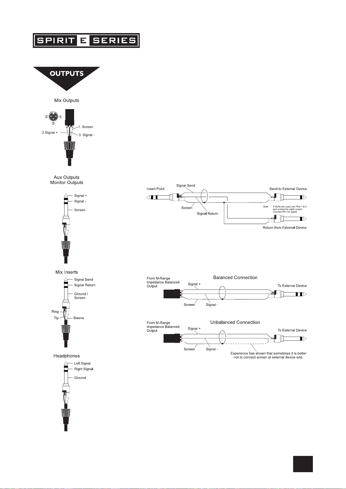
Mix Inserts
The unbalanced, pre-fade Mix insert point is a break in the output signal path to
allow the connection of, for example, a compressor/limiter or graphic equaliser.
The Insert is a 3-pole ‘A’ gauge jack socket which is normally bypassed. When a
jack is inserted, the signal path is broken, just before the mix fader.
The mix signal appears on the TIP of the plug and is returned on the RING. A ‘Y’ lead
may be required to connect to equipment with separate send and return jacks as
shown below:
Mix Outputs
The MIX outputs are on XLR’s, wired as shown, and incorporate impedance balancing, allowing long cable runs to balanced amplifiers and other equipment.
13
Page 14

USER GUIDEUSER GUIDE
USER GUIDE
USER GUIDEUSER GUIDE
Aux Outputs
The Aux outputs are on 3-pole ‘A’ gauge jack sockets, wired as shown on the left,
and are balanced, allowing long cable runs to balanced amplifiers and other equipment.
Headphones
The PHONES output is a 3-pole ‘A’ gauge jack, wired as a stereo output as shown,
ideally for headphones of 200Ω or greater. 8Ω headphones are not recommended.
Polarity (Phase)
You will probably be familiar with the concept of polarity in electrical signals and
this is of particular importance to balanced audio signals. Just as a balanced
signal is highly effective at cancelling out unwanted interference, so two microphones picking up the same signal can cancel out, or cause serious degradation of
the signal if one of the cables has the +ve and -ve wires reversed. This phase
reversal can be a real problem when microphones are close together and you should
therefore always take care to connect pins correctly when wiring audio cables.
Grounding and Shielding
For optimum performance use balanced connections where possible and ensure
that all signals are referenced to a solid, noise-free earthing point and that all signal
cables have their screens connected to ground. In some unusual circumstances, to
avoid earth or ground ‘loops’ ensure that all cable screens and other signal earths
are connected to ground only at their source and not at both ends.
If the use of unbalanced connections is unavoidable, you can minimise noise by
following these wiring guidelines:
• On INPUTS, unbalance at the source and use a twin screened cable as
though it were balanced.
• On OUTPUTS, connect the signal to the +ve output pin, and the ground of
the output device to -ve. If a twin screened cable is used, connect the
screen only at the mixer end.
• Avoid running audio cables or placing audio equipment close to thyristor
dimmer units or power cables.
• Noise immunity is improved significantly by the use of low impedance
sources, such as good quality professional microphones or the outputs from
most modern audio equipment. Avoid cheaper high impedance microphones, which may suffer from interference over long cable runs, even with
well-made cables.
Grounding and shielding is still seen as a black art, and the suggestions above are
only guidelines. If your system still hums, an earth/ground loop is the most likely
cause. Two examples of how an earth loop can occur are shown below.
14
WARNING! Under NO circumstances must the AC
power mains earth be disconnected from the mains
lead.
Page 15

PROBLEM SOLVING
Basic problem solving is within the scope of any user if a few basic rules are
followed.
• Get to know the Block Diagram of your console (see page 38).
• Get to know what all parameters and/or connections in the system are
supposed to do.
• Learn where to look for common trouble spots.
The Block Diagram is a representative sketch of all the components of the console, showing how they connect together and how the signal flows through the
system. Once you have become familiar with the various component blocks you
will find the Block Diagram is quite easy to follow and you will have gained a
valuable understanding of the internal structure of the console.
Each Component has a specific function and only by getting to know what each
part is supposed to do will you be able to tell if there is a genuine fault! Many
“faults” are the result of incorrect connection or control settings which may have
been overlooked.
Basic Troubleshooting is a process of applying logical thought to the signal path
through the console and tracking down the problem by elimination.
• Swap input connections to check that the source is really present. Check
both Mic and Line inputs.
• Eliminate sections of the channel by using the insert point to re-route the
signal to other inputs that are known to be working.
• Route channels to different outputs or to auxiliary sends to identify prob-
lems on the Master section.
• Compare a suspect channel with an adjacent channel which has been
set up identically. Use SOLO to monitor the signal in each section.
• Insert contact problems may be checked by using an insert bypass jack
with tip and ring shorted together as shown below. If the signal appears
when the jack is inserted it shows that there is a problem with the
normalling contacts on the jack socket, caused by wear or damage, or
often just dirt or dust. Keep a few in your gig tool box.
If in doubt please contact Soundcraft customer support.
PRODUCTS UNDER WARRANTY
USA customers should contact the National Service Manager at Soundcraft USA,
telephone: (615) 360-0458, e-mail: soundcraft-usa@harman.com.
UK customers should contact their local Dealer.
Outside the UK and USA, customers are requested to contact their territorial
distributor who is able to offer support in the local time zone and language.
Please see the Distributor listings on our website (http://www.soundcraft.com)
to locate your Local Distributor.
OUT-OF-WARRANTY PRODUCTS
For out-of-warranty consoles purchased in the United Kingdom, please contact
the Customer Services Department (e-mail: csd@soundcraft.com) at the factory
in Potters Bar, Hertfordshire: Telephone +44 (0)1707 665000.
For all other out-of-warranty consoles, please contact the appropriate territorial
distributor.
When mailing or faxing please remember to give as much information as possible. This should include your name, address and a daytime telephone number.
Should you experience any difficulty please contact Customer Services Department (e-mail: csd@soundcraft.com)
15
Page 16

USER GUIDEUSER GUIDE
USER GUIDE
USER GUIDEUSER GUIDE
Mono Input ChannelMono Input Channel
Mono Input Channel
Mono Input ChannelMono Input Channel
1
2
3
4
5
6
1 Mic Input
The MIC input accepts XLR-type connectors and is designed to suit a wide range of
BALANCED or UNBALANCED signals. Professional dynamic, condenser or ribbon mics
are best because these will be LOW IMPEDANCE. You can use low-cost HIGH IMPEDANCE mics, but the level of background noise will be higher. If you turn the PHANTOM
POWER on (top right-hand side of the mixer) the socket provides a suitable powering
voltage for professional condenser mics.
ONLY connect condenser microphones with the +48V
powering OFF, and ONLY turn the +48V powering on
or off with all output faders DOWN, to prevent
damage to the mixer or external devices.
TAKE CARE when using unbalanced sources, which may be damaged by the phantom
power voltage on pins 2 & 3 of the XLR connector.
Unplug any mics if you want to use the LINE Input. The input level is set using the GAIN
knob.
2 Line Input
Accepts 3-pole ‘A’ gauge (TRS) jacks. Use this input for sources other than mics, such
as keyboards, drum machines, synths, tape machines or DI’d guitars. The input is
BALANCED for low noise and top quality from professional equipment, but you can use
UNBALANCED sources by wiring up the jacks as shown below, although you should then
keep cable lengths as short as possible. Unplug anything in the MIC input if you want to
use this socket. Set the input level using the GAIN knob.
7
8
q
0
9
3 Insert Point
The unbalanced, pre-EQ insert point is a break in the channel signal path, allowing
limiters, compressors, special EQ or other signal processing units to be added in the
signal path. The Insert is a 3-pole ‘A’ gauge jack socket which is normally bypassed.
When a jack is inserted, the signal path is broken, just before the EQ section.
The Send may be tapped off as an alternative pre-fade, pre-EQ direct output if required,
using a lead with tip and ring shorted together so that the signal path is not interrupted
(see below).
16
Page 17

4 Gain
This knob sets how much of the source signal is sent to the rest of the mixer. Too high, and
the signal will distort as it overloads the channel. Too low, and the level of any background
hiss will be more noticeable and you may not be able to get enough signal level to the
output of the mixer.
Note that some sound equipment, particularly that intended for domestic use, operates at
a lower level (-10dBV) than professional equipment and will therefore need a higher gain
setting to give the same output level.
See “Initial Setup” on page 23 to learn how to set GAIN correctly.
5 Equaliser
The Equaliser (EQ) allows fine manipulation of the sound, particularly to improve the
sound in live PA applications where the original signal is often far from ideal and where
slight boosting or cutting of particular voice frequencies can really make a difference to
clarity. There are three sections giving the sort of control usually only found on much larger
mixers. The EQ knobs can have a dramatic effect, so use them sparingly and listen
carefully as you change any settings so that you get to know how they affect the sound.
HF EQHF EQ
HF EQ
HF EQHF EQ
Turn to the right to boost high (treble) frequencies above 12kHz by up to 15dB, adding
crispness to cymbals, vocals and electronic instruments. Turn to the left to cut by up to
15dB, reducing hiss or excessive sibilance which can occur with certain types of microphone. Set the knob in the centre-detented position when not required.
MID EQMID EQ
MID EQ
MID EQMID EQ
There are two knobs which work together to form a SWEPT MID EQ. The lower knob
provides 15dB of boost and cut, just like the HF EQ knob, but the frequency at which this
occurs can be set by the upper knob over a range of 140Hz to 3kHz. This allows some
truly creative improvement of the signal in live situations, because this mid band covers
the range of most vocals. Listen carefully as you use these controls together to find how
particular characteristics of a vocal signal can be enhanced or reduced. Set the lower
knob to the centre-detented position when not required.
LF EQLF EQ
LF EQ
LF EQLF EQ
Turn to the right to boost low (bass) frequencies below 60Hz by up to 15dB, adding
warmth to vocals or extra punch to synths, guitars and drums. Turn to the left to cut low
frequencies by up to 15dB for reducing hum, stage rumble or to improve a mushy sound.
Set the knob to the centre-detented position when not required.
6 Aux Sends
These are used to set up separate mixes for FOLDBACK, EFFECTS or recording, and the
combination of each Aux Send is mixed to the respective Aux Output. For Effects it is
useful for the signal to fade up and down with the fader (this is called POST-FADE), but for
Foldback or Monitor feeds it is important for the send to be independent of the fader (this
is called PRE-FADE).
AUX SENDS 1 and 2 are both globally switchable between pre and post-fade (see master
section on page 21/22).
7 PAN
This control sets the amount of the channel signal feeding the Left and Right MIX buses,
allowing you to move the source smoothly across the stereo image. When the control is
turned fully left or right you are able to route the signal at unity gain to either left or right
outputs individually.
17
Page 18

USER GUIDEUSER GUIDE
USER GUIDE
USER GUIDEUSER GUIDE
1
8 MUTE
All outputs from the channel except inserts are on when the MUTE switch is released and
muted when the switch is down, allowing levels to be pre-set before the signal is required.
2
3
4
5
6
9 INPUT CHANNEL FADER
The 100mm FADER, with a custom-designed law to give even smoother control of the
overall signal level in the channel strip, allows precise balancing of the various source
signals being mixed to the Master Section. You get most control when the input GAIN is
set up correctly, giving full travel on the fader. See the “Initial Setup” section on page 23
for help in setting a suitable signal level.
0 SOLO
When the latching SOLO switch is pressed, the pre-fade pre-mute signal is fed to the
headphones, control room output and meters, where it replaces the MIX. The SOLO LED
on the Master section illuminates to warn that a SOLO is active. This is a useful way of
listening to any required input signal without interrupting the main mix, for making adjustments or tracing problems. When SOLO is pressed anywhere on the console, the Control
Room outputs automatically switch from monitoring the Mix Outputs.
q PEAK LED
This LED will light when the signal level approaches clipping at any of the three monitored
points:
a) PRE-EQ
b) POST-EQ
c) POST-FADE
7
8
q
0
9
18
Page 19

1
2
3
4
5
6
9
8
STEREO INPUT CHANNELSSTEREO INPUT CHANNELS
STEREO INPUT CHANNELS
STEREO INPUT CHANNELSSTEREO INPUT CHANNELS
1 INPUTS STEREO 1/2
These inputs accept 3-pole ‘A’ gauge (TRS) jacks. Use these inputs for sources such as
keyboards, drum machines, synths, tape machines or processing units. The inputs are
BALANCED for low noise and top quality from professional equipment, but you can use
UNBALANCED sources by wiring up the jacks as shown in the “Wiring it Up” section
earlier in this manual, although you should then keep cable lengths as short as possible.
Mono sources may be used by plugging into the left jack only.
2 GAIN
The GAIN control sets the level of the channel signal.
3 EQUALISER
HF EQHF EQ
HF EQ
HF EQHF EQ
Turn to the right to boost high (treble) frequencies, adding crispness to percussion from
drum machines, synths and electronic instruments. Turn to the left to cut these frequencies, reducing hiss or excessive brilliance. Set the knob in the centre-detented position
when not required. The control has a shelving response giving 15dB of boost or cut at
12kHz.
LF EQLF EQ
LF EQ
LF EQLF EQ
Turn to the right to boost low (bass) frequencies, adding extra punch to synths, guitars
and drums. Turn to the left to reduce hum, boominess or improve a mushy sound. Set
the knob to the centre-detented position when not required. The control has a shelving
response giving 15dB of boost or cut at 60Hz.
4 AUX SENDS
These are used to set up a separate mixes for FOLDBACK, EFFECTS or recording, and the
combination of each Aux Send is mixed to the respective Aux Output at the rear of the
mixer. For Effects it is useful for the signal to fade up and down with the fader (this is
called POST-FADE), but for Foldback or Monitor feeds it is important for the send to be
independent of the fader (this is called PRE-FADE).
AUX SENDS 1 and 2 are both globally switchable between pre and post-fade (see master section on page 21/22). The send pots are fed with a mono sum of the L & R signals.
7
5 BALANCE
This control sets the amount of the channel signal feeding the Left and Right MIX buses,
allowing you to balance the source in the stereo image. When the control is turned fully
right or left you feed only that side of the signal to the mix. Unity gain is provided by the
control in the centre-detented position.
6 MUTE
All outputs from the channel are enabled when the MUTE switch is released and muted
when the switch is down.
19
Page 20

USER GUIDEUSER GUIDE
USER GUIDE
USER GUIDEUSER GUIDE
1
7 FADER
The 100mm FADER gives you smooth control of the overall signal level in the channel
strip, allowing precise balancing of the various source signals being mixed to the Master
Section. It is important that the input level is set correctly to give maximum travel on the
fader which should normally be used at around the “0” mark. See the “Initial Setup”
section on page 23 for help in setting the right level.
8 SOLO
When the latching SOLO switch is pressed, the pre-fade pre-mute signal is fed in mono
to the headphones, control room output and meters, where it replaces the MIX. The
SOLO LED on the Master section illuminates to warn that a SOLO is active. The Left and
Right meters display the SOLO signal in mono. This is a useful way of listening to any
required input signal without interrupting the main mix, for making adjustments or tracing
problems.
2
3
4
5
6
9
8
9 CHANNEL PEAK LED
This LED will light when the signal level approaches clipping at any of the three monitored points:
a) PRE-EQ
b) POST-EQ
c) POST-FADE
20
7
Page 21

q
r
4
7
6
Master SectionMaster Section
Master Section
Master SectionMaster Section
1 PHANTOM POWER
Many professional condenser mics need PHANTOM POWER, which is a method
of sending a powering voltage down the same wires as the mic signal. Press
the switch to enable the +48V power to all of the MIC inputs. The adjacent
LED illuminates when the power is active.
WARNING: TAKE CARE when using unbalanced mics which may be
damaged by the phantom power voltage. Balanced dynamic mics
can normally be used with phantom power switched on (contact your
microphone manufacturer for guidance).
Mics should always be plugged in, and all output faders set to minimum before switching the Phantom Power ON to avoid damage to
external equipment
1
e
w
0
t
5
9
8
2
2 POWER INDICATOR
This LED lights to show when power is connected to the console.
3 MASTER FADERS
The MASTER FADERS set the final level of the MIX outputs, and separate
faders are provided for each output. These should normally be set close to
the ‘0’ mark if the input GAIN settings have been correctly set, to give maximum travel on the faders for smoothest control.
4 MIX OUTPUTS & INSERTS
The Mix LEFT and RIGHT outputs are sent from the XLR sockets as balanced
signals. The Mix INSERT points are on 3-pole ‘A’ gauge jacks and are unbalanced.
5 BARGRAPH METERS
The three-colour peak reading BARGRAPH METERS normally show the level
of the MIX RIGHT and MIX LEFT outputs, giving you a constant warning of
excessive peaks in the signal which might cause overloading. Aim to keep
the signal within the amber segments at peak levels for best performance.
Similarly, if the output level is too low and hardly registering at all on the
meters, the level of background noise may become significant. Take care to
set up the input levels for best performance.
When any SOLO switch is pressed, the meters switch to show the selected
SOLO signal on both meters, in mono; the SOLO LED also lights.
3
6 RECORD OUTPUTS
These two RCA outputs carry a copy of the MIX L and MIX R signals. They
allow the use of a recording device, e.g. DAT player, Minidisc, Cassette tape
recorder etc.
7 PLAYBACK IN
These two RCA phono sockets are unbalanced Left and Right line-level inputs, used for connecting a recording device.
21
Page 22

USER GUIDEUSER GUIDE
USER GUIDE
USER GUIDEUSER GUIDE
q
r
4
7
6
1
e
w
0
8 PLAYBACK TO MIX
Press this switch to route the Playback in signals, connected to the Left and Right
RCA sockets 7, to the MIX Left/Right signal at the MIX outputs.
9 MONITOR PLAYBACK
Press this switch to route the Playback signal to the monitor and phones, overriding the default Monitor/Phones signal.
0 MONITOR LEVEL
This control sets the level to the MONITOR LEFT & RIGHT outputs. If headphones
are plugged into the PHONES jack, the headphone level will track the Monitor
Level.
q MONITOR OUTPUTS
The Monitor Outputs are on 3-pole ‘A’ gauge jacks and are balanced connections
w PHONES LEVEL
This control sets the output level to the Headphone outputs. If headphones are
plugged into the PHONES jack, then the knob sets a comfortable headphone
listening level without affecting the Monitor output levels.
t
5
9
8
2
3
e HEADPHONES JACK
The PHONES output is a 3-pole ‘A’ gauge jack, wired as a stereo output as
shown, ideally for headphones of 200Ω or greater. 8Ω headphones are not
recommended.
r AUX OUTPUTS (1 & 2)
These outputs are on 3-pole ‘A’ gauge jacks and are balanced outputs.
t AUX PRE/POST SWITCHES
These two switches globally switch the AUX 1 and AUX 2 feeds, respectively, on
all the input modules to be either pre-fade or post-fade.
22
Page 23

USING YOUR USING YOUR
USING YOUR
USING YOUR USING YOUR
The final sound from your PA system can only ever be as good as the weakest link in the chain,
and especially important is the quality of the source signal because this is the starting point of
the chain. Just as you need to become familiar with the control functions of your mixer, so you
must recognise the importance of correct choice of inputs, microphone placement and input
channel settings. However, no amount of careful setting up can take account of the spontaneity
and unpredictability of live performance. The mixer must be set up to provide “spare” control
range to compensate for changing microphone position and the absorption effect of a large
audience (different acoustic characteristics from soundcheck to show).
SPIRIT SPIRIT
SPIRIT
SPIRIT SPIRIT
E SERIES CONSOLEE SERIES CONSOLE
E SERIES CONSOLE
E SERIES CONSOLEE SERIES CONSOLE
MICROPHONE PLACEMENT
Careful microphone placement and the choice of a suitable type of microphone for the job is
one of the essentials of successful sound reinforcement. The diagrams on the left show the
different pick-up patterns for the most common types of microphone. Cardioid microphones
are most sensitive to sound coming from in front, and hypercardioid microphones offer even
greater directivity, with a small amount of pickup behind the microphone. These types are ideal
for recording vocalists or instruments, where rejection of unwanted sounds and elimination of
feedback is important. The aim should be to place the microphone as close as physically
possible to the source, to cut out unwanted surrounding sounds, allow a lower gain setting on
the mixer and avoid feedback. Also a well chosen and well placed microphone should not need
any appreciable equalisation.
There are no exact rules - let your ears be the judge. In the end, the position that gives the
desired effect is the correct position!
INITIAL SETUP
Once you have connected up your system (see the sections on connection and wiring earlier in
this manual for guidance) you are ready to set initial positions for the controls on your mixer.
The front panel drawing on page 8 shows typical initial
control positions which is a useful guide to setting up the
mixer for the first time.
Set up individual input channel as follows:
• Connect your sources (microphone, keyboard etc.) to the required inputs.
WARNING: Phantom powered mics should be connected before the +48V is switched
on. Ensure the PA system is OFF when switching phantom power on or off.
• Set Master faders at 0, input faders at 0, and set power amplifier levels to about 70%.
• Provide a typical performance level signal and press the SOLO button on the first chan-
nel, monitoring the level on the bargraph meters.
• Adjust the input gain until the meter display is in the amber section, with occasional
peaks to the first red LED at a typical maximum source level. This allows sufficient
headroom to accommodate peaks and establishes the maximum level for normal operation (but see note below).
• Repeat this procedure on other channels as required. As more channels are added to
the mix, the meters may move into the red section. Adjust the overall level using the
Master Faders if necessary.
• Listen carefully for the characteristic sound of “feedback”. If you cannot achieve satis-
factory input level setting without feedback, check microphone and speaker placement
and repeat the exercise. If feedback persists, it may be necessary to use a Graphic
Equaliser to reduce the system response at particular resonant frequencies.
Note:Note:
Note:
Note:Note:
The initial settings should only be regarded as a starting point for your mix. It is important to
remember that many factors affect the sound during a live performance, for instance the size of
the audience!
23
Page 24

USER GUIDEUSER GUIDE
USER GUIDE
USER GUIDEUSER GUIDE
You are now ready to start building the mix and this should be done progressively,
listening carefully for each component in the mix and watching the meters for any
hint of overload. If this occurs, back off the appropriate Channel Fader slightly until
the level is out of the red segments, or adjust the Master Faders.
Remember that the mixer is a mixer, not an amplifier. Increasing the overall level is
the job of the amplifier, and if it is impossible to provide adequate level, it is
probable that the amplifier is too small for the application. Choose your amplifier
carefully, and do not try to compensate for lack of power by using the mixer to
increase output level.
Note:Note:
Note:
Note:Note:
The level of any source signal in the final output is affected by many factors, principally the Input Gain control, Channel Fader and Mix Faders. You should try to use
only as much microphone gain as required to achieve a good balance between
signals, with the faders set as described above.
If the input gain is set too high, the channel fader will need to be pulled down too
far in compensation to leave enough travel for successful mixing and there is a
greater risk of feedback because small fader movements will have a very significant
effect on output level. Also there will be a chance of distortion as the signal overloads the channel and causes clipping.
If the gain is set too low, you will not find enough gain on the faders to bring the
signal up to an adequate level, and backgound hiss will be more noticeable.
This is illustrated below:
24
Page 25

FITTING RACKMOUNT EARSFITTING RACKMOUNT EARS
FITTING RACKMOUNT EARS
FITTING RACKMOUNT EARSFITTING RACKMOUNT EARS
Note: when rackmounting the E6 and E8 a rack
extender is available from Soundcraft to make
the console fit into a 19" frame.
25
Page 26

USER GUIDEUSER GUIDE
USER GUIDE
USER GUIDEUSER GUIDE
APPLICAAPPLICA
APPLICA
APPLICAAPPLICA
APPLICATION 1 - LIVE SOUND REINFORCEMENT
TIONSTIONS
TIONS
TIONSTIONS
26
Using Delay in REINFORCEMENT SYSTEMSUsing Delay in REINFORCEMENT SYSTEMS
Using Delay in REINFORCEMENT SYSTEMS
Using Delay in REINFORCEMENT SYSTEMSUsing Delay in REINFORCEMENT SYSTEMS
The drawing below illustrates how to calculate delay settings for fill speakers in multiple speaker
installations.
Page 27

APPLICATION 2 - MULTISPEAKER APPLICATIONS
This configuration demonstrates how multiple speaker configurations can be driven by the Spirit E Series.
APPLICATION 3 - PLACES OF WORSHIP
This configuration uses the Aux 2 output to drive an induction loop for the hard of hearing. Aux 1 output is used to generate foldback
monitoring for the speaker/singer. The main outputs are used to drive the main speaker system. The record and playback connections
are used to pass audio to and from a DAT machine or CDR.
27
Page 28

USER GUIDEUSER GUIDE
USER GUIDE
USER GUIDEUSER GUIDE
APPLICATION 4 - RECORDING
The insert points on channels 1-8 may be used to feed a multitrack recorder as shown (link the send and return signals). The Mix
outputs are used for a preliminary stereo mix on a DAT recorder.
APPLICATION 5 - LINKING TWO SPIRIT E SERIES CONSOLES
28
Page 29

GlossarGlossar
Glossar
GlossarGlossar
AFL (After Fade Listen) a function that allows the operator to monitor the post-fade signal
auxiliary send an output from the console comprising a mix of signals from
balance the relative levels of the left and right channels of a stereo signal.
balanced a method of audio connection which ‘balances’ the wanted signal
clipping the onset of severe distortion in the signal path, usually caused
DAT Digital Audio Tape, a cassette-based digital recording format.
dB (decibel) a ratio of two voltages or signal levels, expressed by the equation
DI(direct injection)/DI Box the practice of connecting an electric musical instrument directly
equaliser a device that allows the boosting or cutting of selected bands of
fader a linear control providing level adjustment.
feedback the `howling’ sound caused by bringing a microphone too close
foldback a feed sent back to the artistes via loudspeakers or headphones
frequency response the variation in gain of a device with frequency.
gain the amount of amplication in level of the signal.
headroom the available signal range above the nominal level before clipping
impedance balancing a technique used on unbalanced outputs to minimise the effect
insert a break point in the signal path to allow the connection of
pan (pot) abbreviation of ‘panorama’: controls levels sent to left and right
peaking the point at which a signal rises to its maximum instantaneous
peak LED a visual indication of the signal peaking just before the onset of
SOLO a function that allows the operator to monitor the pre-fade signal
yy
y
yy
in a channel independently of the main mix.
channels and groups derived independently of the main stereo
mixes.
between two wires and a screen which carries no signal. Any
interference is picked up equally by the two wires, which results
in cancellation of the unwanted signal. In this guide, the term
can refer to various circuit architectures. Connection details are
given in relevant sections.
by the peak signal voltage being limited by the circuit’s power
supply voltage.
dB=20Log10 (V1/V2). Adding the suffix ‘u’ denotes the ratio is
relative to 0.775V RMS.
to the input of the mixing console, rather than to an amplifier and
loudspeaker which is covered by a microphone feeding the
console.
frequencies in the signal path.
to a loudspeaker driven from its amplified signal.
to enable them to monitor the sounds they are producing.
occurs.
of hum and interference when connecting to external balanced
inputs.
external devices, for instance signal processors or other mixers at
line level signals. Nominal levels can be anywhere between
-0dBu to +6dBu, usually coming from a low impedance source.
outputs.
level, before falling back down again. It can also describe an
equaliser response curve affecting only a band of frequencies,
(like on a graphic equaliser), “peaking” at the centre of that band.
clipping, which will distort the signal.
in a channel independently of the main mix.
29
Page 30

USER GUIDEUSER GUIDE
USER GUIDE
USER GUIDEUSER GUIDE
phase a term used to describe the relationship of two audio signals. In-
phase signals reinforce each other, out-of-phase signals result in
cancellation. Phase is a measurement of relative displacement
between two waves of identical frequency.
polarity a term used to describe the orientation of the positive and
negative poles of an audio connection. Normally connections are
made with positive to positive, negative to negative. If this is
reversed, the result will be out-of-phase signals (see ‘phase’
above).
post-fade the point in the signal path after the monitor or master fader and
therefore affected by fader position.
pre-fade the point in the signal path before the monitor or master fader
position and therefore unaffected by the fader position.
rolloff a fall in gain at the extremes of the frequency response.
shelving an equaliser response affecting all frequencies above or below
the break frequency i.e. a highpass or lowpass derived response.
spill acoustic interference from other sources.
transient a momentary rise in the signal level.
unbalanced a method of audio connection which uses a single wire and the
cable screen as the signal return. This method does not provide
the noise immunity of a balanced input (see above).
+48V the phantom power supply, available at the channel mic inputs,
for condenser microphones and active DI boxes.
30
Page 31

TYPICAL SPECIFICATYPICAL SPECIFICA
TYPICAL SPECIFICA
TYPICAL SPECIFICATYPICAL SPECIFICA
Noise (22Hz-22kHz measurNoise (22Hz-22kHz measur
Noise (22Hz-22kHz measur
Noise (22Hz-22kHz measurNoise (22Hz-22kHz measur
Mic EIN @ max gain, 150 W source impedance ............................................................................ -128dBu
Mix @max, faders down ................................................................................................................ <-85dBu
CrCr
osstalk (typ. @ 1kHz)osstalk (typ. @ 1kHz)
Cr
osstalk (typ. @ 1kHz)
CrCr
osstalk (typ. @ 1kHz)osstalk (typ. @ 1kHz)
Channel mute ...................................................................................................................................>96dB
Fader cut-off (rel +10 mark) .............................................................................................................>96dB
Aux send pot offness ........................................................................................................................>86dB
FrFr
equency requency r
Fr
equency r
FrFr
equency requency r
Mic/Line input to any output ................................................................................ +/- 0.5dB 20Hz – 20kHz
THD+NoiseTHD+Noise
THD+Noise
THD+NoiseTHD+Noise
Mic gain 30dB, -30dBu input
Mix out, fader max @ 1kHz ...........................................................................................................<0.007 %
Input & output ImpedancesInput & output Impedances
Input & output Impedances
Input & output ImpedancesInput & output Impedances
Mic input .......................................................................................................................................... 2.4kΩ
Line input .......................................................................................................................................... 11kΩ
Stereo input .................................................................................................................................... 100kΩ
Outputs ............................................................................................................................................... 75Ω
Input & output levelsInput & output levels
Input & output levels
Input & output levelsInput & output levels
Mic input max level......................................................................................................................... +17dBu
Line input max level........................................................................................................................+30dBu
Stereo input max level ....................................................................................................................+30dBu
Mix output max level.......................................................................................................................+20dBu
Headphones (@ 200Ω) .................................................................................................................. 300mW
EQEQ
EQ
EQEQ
EQ Bands (Mono input) +/- 15dB
Lo....................................................................................................................................................... 80Hz
Mid (swept) ........................................................................................................................... 140Hz – 3kHz
Hi ......................................................................................................................................................12kHz
Q ........................................................................................................................................................... 1.5
EQ Bands (stereo input) +/- 15dB
Lo...................................................................................................................................................... 80Hz
Hi ......................................................................................................................................................12kHz
esponseesponse
esponse
esponseesponse
TIONSTIONS
TIONS
TIONSTIONS
ement bandwidth)ement bandwidth)
ement bandwidth)
ement bandwidth)ement bandwidth)
31
Page 32

USER GUIDEUSER GUIDE
USER GUIDE
USER GUIDEUSER GUIDE
WEIGHTWEIGHT
WEIGHT
WEIGHTWEIGHT
E6 ............................................................................................................................... 5.75 kg (12.68 lbs)
E8 ............................................................................................................................... 6.75 kg (14.88 lbs)
E12 ............................................................................................................................. 7.75 kg (17.09 lbs)
AVERAGE POWER CONSUMPTION (QUIESCENT)AVERAGE POWER CONSUMPTION (QUIESCENT)
AVERAGE POWER CONSUMPTION (QUIESCENT)
AVERAGE POWER CONSUMPTION (QUIESCENT)AVERAGE POWER CONSUMPTION (QUIESCENT)
E6 ................................................................................................................................................ 13 Watts
E8 ............................................................................................................................................. 14.5 Watts
E12 .............................................................................................................................................. 17 Watts
MIN / MAX OPERAMIN / MAX OPERA
MIN / MAX OPERA
MIN / MAX OPERAMIN / MAX OPERA
Centigrade / Farenheit.................................................................................... 0°C - 50°C / 32°F - 122°F
TING TEMPERATING TEMPERA
TING TEMPERA
TING TEMPERATING TEMPERA
TURE (E SERIES FTURE (E SERIES F
TURE (E SERIES F
TURE (E SERIES FTURE (E SERIES F
AMILAMIL
AMIL
AMILAMIL
Y)Y)
Y)
Y)Y)
32
Page 33

E6 DimensionsE6 Dimensions
E6 Dimensions
E6 DimensionsE6 Dimensions
33
Page 34

USER GUIDEUSER GUIDE
USER GUIDE
USER GUIDEUSER GUIDE
E8 DimensionsE8 Dimensions
E8 Dimensions
E8 DimensionsE8 Dimensions
34
Page 35

E12 DimensionsE12 Dimensions
E12 Dimensions
E12 DimensionsE12 Dimensions
35
Page 36

USER GUIDEUSER GUIDE
USER GUIDE
USER GUIDEUSER GUIDE
TYPICAL CONNECTING LEADSTYPICAL CONNECTING LEADS
TYPICAL CONNECTING LEADS
TYPICAL CONNECTING LEADSTYPICAL CONNECTING LEADS
36
Page 37

37
Page 38

USER GUIDEUSER GUIDE
USER GUIDE
USER GUIDEUSER GUIDE
SYSTEM BLOCK DIAGRAMSYSTEM BLOCK DIAGRAM
SYSTEM BLOCK DIAGRAM
SYSTEM BLOCK DIAGRAMSYSTEM BLOCK DIAGRAM
38
Page 39

CONTROL POSITION MARK-UP SHEETCONTROL POSITION MARK-UP SHEET
CONTROL POSITION MARK-UP SHEET
CONTROL POSITION MARK-UP SHEETCONTROL POSITION MARK-UP SHEET
To assist you in restoring the console to a previous setting you may copy this sheet as many times as you like, and use the copies to
make a note of your control settings.
39
Page 40

USER GUIDEUSER GUIDE
USER GUIDE
USER GUIDEUSER GUIDE
CONTROL POSITION MARK-UP SHEETCONTROL POSITION MARK-UP SHEET
CONTROL POSITION MARK-UP SHEET
CONTROL POSITION MARK-UP SHEETCONTROL POSITION MARK-UP SHEET
To assist you in restoring the console to a previous setting you may copy this sheet as many times as you like, and use the copies to
make a note of your control settings.
40
Page 41

CONTROL POSITION MARK-UP SHEETCONTROL POSITION MARK-UP SHEET
CONTROL POSITION MARK-UP SHEET
CONTROL POSITION MARK-UP SHEETCONTROL POSITION MARK-UP SHEET
To assist you in restoring the console to a previous setting you may copy this sheet as many times as you like, and use the copies to
make a note of your control settings.
41
Page 42

USER GUIDEUSER GUIDE
USER GUIDE
USER GUIDEUSER GUIDE
42
 Loading...