

Page 1
RKDT-PPLX Family Installation Instructions
.90”
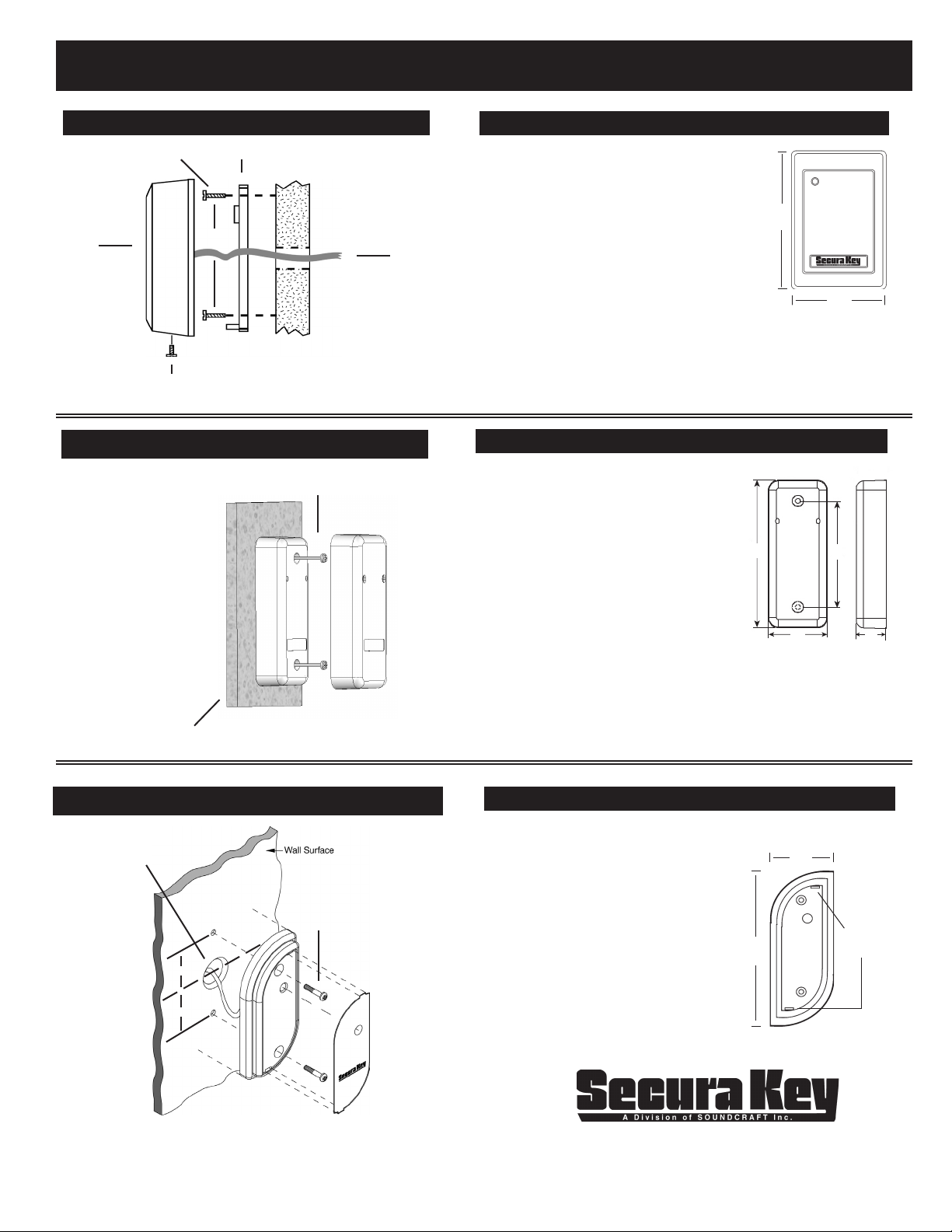
SWITCHPLATE INSTALLATION DIAGRAM
Use appropriate
Fastener
Reader
Housing
¿
Use supplied
screw
Mounting Plate
¿
¿
3.28
¿
¿
¿
¿
3/4” diameter
through hole
for cables.
Mounting
Surface
MULLION INSTALLATION DIAGRAM
Use supplied screws
l
1/2” Diameter hole in
mounting surface for
wiring
Mounting
Surface
l
INSTALLATION STEPS FOR RKDT-SA-S/PPLX:
1. If mounting the unit outdoors, especially on a
rough surface like masonry, we recommend
th at you sea l th e re ad er wit h si li cone
caulking.
2. Drill holes as needed per installation diagram
shown to the left or install a single gang j-box.
3. Run eld wiring to reader location and feed
into j-box or through cable hole.
4. Attach the mounting plate to the mounting
su rfa ce or j-bo x with the ap pro priat e
fasteners.
5. Splice the connector pigtail to eld wiring. Insert
the connector into the back of the reader.
6. Attach the housing to the mounting plate by inserting the two tabs
inside the top of the housing into the two slots at the top of the
mounting plate.
7. Secure by installing supplied screw into the hole at the bottom of the
reader.
¿
4.50
¿
¿
3.20
¿
INSTALLATION STEPS FOR RKDT-SA-M
1. If mounting the unit outdoors, especially
on a rough surface l ike maso nry, we
recommend that you seal the reader with
silicone caulking.
2. Drill a hole for the eld wiring. Remove
decorative cover from reader. Using the
reader as a template, mark the location
of the two mounting holes. Drill two 1/8”
pilot holes for the mounting screws.
3. Run eld wiring to reader location and
feed through cable hole.
4. Splice the connector pigtail to eld wiring.
Insert the connector into the back of the reader.
5. Attach the reader to the surface using the two machine screws
provided. These may be replaced with tamper proof screws
(customer supplied).
6. Slip on the decorative cover (if used) until both tabs snap into
place.
4.38”
1.74”
3.14”
.90”
MULLION INSTALLATION DIAGRAM
3/4” Diameter through
hole for cable and
buzzer.
Use appropriate
#6 Fastener
l
l
3322252 7472
1.0”
1.3”
l
l
l
l
INSTALLATION STEPS FOR RKDT-WM
1. Drill holes as needed per installation diagram shown to
the left.
2. Feed cable through 3/4” hole.
3. Attach reader to any at surface
with two #6 screws.
4. Snap label insert into front of
reader to cover screws.
20301 Nordhoff Street, Chatsworth, CA 91311
PHONE (818) 882-0020 • FAX (818) 882-7052
TOLL-FREE (800) 891-0020
Website: www.securakey.com • E-mail: mail@securakey.com
¿
3.50
¿
1.60
¿
¿
¿
LED
Label Tabs
Inser t Here
¿
Page 2
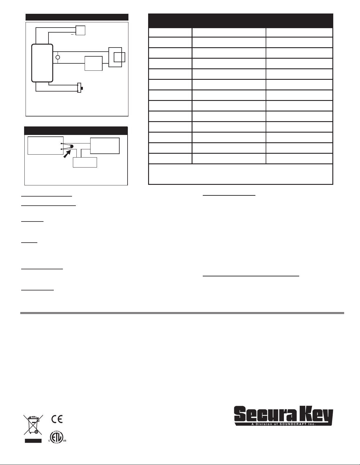
TYPICAL INSTALLATION
Install the enclosed 40-volt MOV (Metal Oxide Varistor) across
RED
BLACK
READER
Note: Use separate power supplies for maglock / strike
For Maglock, see “Configure Relay Output” section in Manual.
* Relay defaults to Normally Open.
+
12
POWER
VDC
SUPPLY
OUTPUT RELAY
WHITE/BLACK
VOM
WHITE/BROWN
BROWN
BLACK
and for access control unit.
LOCK
POWER
SUPPLY
REMOTE OPEN
µ
NORMALLY OPEN
MAGLOCK
STRIKE
SWITCH
*/
RKDT/PPLX WIRING CONNECTIONS
WIRE COLOR REMOTE OPEN STANDALONE LED CONTROL WIEGAND
GREEN DATA-0 DATA-0
WHITE DATA-1 DATA-1
VIOLET RXD N/A
GRAY TXD N/A
ORANGE GREEN LED INPUT (3, 1) GREEN LED INPUT (3, 1)
BROWN REX LATCH + TIMER (2, 1) RED LED INPUT (3, 1)
YELLOW BEEPER INPUT (1) BEEPER INPUT (1)
BLUE HOLD (1) HOLD (1)
Installation of Metal Oxide Varistor
ACCESS
UNIT
RELAY +
RELAY -
INSTALL
MOV HERE
MAGLOCK /
STRIKE
CONTROL
the relay contacts in the access control unit, as shown. The
Access Control Unit must have its own power supply.
LOCK
POWER
+
_
SUPPLY
DC
RED 5-14 VDC + 5-14 VDC +
BLACK GROUND --- GROUND ---
WHITE/BLACK RELAY + NA
WHITE/BROWN RELAY - NA
SPECIFICATIONS:
POWER REQUIREMENTS
5-14 VDC, 150 mA Max.
OUTPUTS
SPST Solid State Relay, 1A max. @60 VAC or DC
Normally open or normally closed (eld programmable) (See Operating Guide).
INPUTS
Default is Remote Open (requires contact closure).
Also programmable as Red LED Control for online systems (see Operating Guide).
Additional inputs for Green LED, Beeper and HOLD are available in Wiegand mode.
WIEGAND OUTPUT
Any Wiegand Format up to 40 bits
Maximum Distance: 500 ft. - 5 or 8 conductor 20 gauge cable
ENVIRONMENT
Access Control Unit, Key Tags and Cards
Ambient Temperature -40° to +70°C (-40° to +158°F)
Humidity 0 to 95% (non-condensing)
(1) Connect to GROUND to activate
(2) Input Programmed for Remote Open
(3) Input Programmed for LED/Beeper Control
PARTS SUPPLIED:
Access Control Unit
MOV
Operating Guide
Installation Instructions
Log Sheet
RKDT-SA-S/RKDT-WM/PPLX RKDT-SA-M
Mounting Plate 2, #6 Mounting Screws
2, # 6 Mounting Screws Cable Assembly
1, 4x40 Screw Decorative Cover
1, Security Screw
1, Cable Assembly
1, Snap-In Labels (RKDT-WM Only)
ACCESSORIES (NOT INCLUDED):
RK-HHP Hand-Held Programmer
RK-PS: 9VDC Plug-in Power Supply. It is designed to power
the RKDT-SA-M/SA-S.
Requires 110 Volts AC power.
SK-SR SecuRelay™ - Smart Relay Module DPDT.
INSTRUCTION TO THE USER
FCC ID: NNHDTR1
This equipment has been tested and found to comply with the limits for a class B digital device, pursuant to part 15 of the FCC Rules. These limits are designed
to provide reasonable protection against harmful interference in a residential installation. This equipment generates, uses and can radiate radio frequency
energy and if not installed and used in accordance with the instructions, may cause harmful interference to radio communications. However, there is no
guarantee that interference will not occur in a particular installation. If this equipment does cause harmful interference to radio or television reception, which
can be determined by turning the equipment off and on, the user is encouraged to try to correct the interference by one or more or the following measures:
Reorient or relocate the receiving antenna.
Increase the separation between the equipment and receiver.
Connect the equipment into an outlet of a circuit different from that to which the receiver is connected.
Consult the dealer or an experienced radio/TV technician for help.
In order to maintain compliance with FCC regulations, unshielded cables must be used with this equipment. Operation with non-approved equipment or
shielded cables is likely to result in interference to radio and TV reception. The user is cautioned that changes and modications made to the equipment
without the approval of manufacturer could void the user’s authority to operate this equipment. “This device complies with Part 15 of the FCC rules. Operation
is subject to the following two conditions: (1) this device may not cause harmful interference, and (2) this device must accept any interference received, including
interference that may cause undesired operation.”
20301 Nordhoff Street, Chatsworth, CA 91311
PHONE (818) 882-0020 • FAX (818) 882-7052
TOLL-FREE (800) 891-0020
RoHS
3059349
3322252 7472
Website: www.securakey.com • E-mail: mail@securakey.com
 Loading...