

Page 1

SOUNDCRAFT
USER GUIDE
Page 2

© Soundcraft Electronics Ltd. 1995
All rights re ser ve d
Parts of th e de si gn of t his pr oduc t are prote c te d by wor ldwide patent s.
Part No. ZM01 03-01
Informat ion in this manual is subject t o change without notice and does not repre sent
a commitment on the part of the vendor. Soundcraft Electronics Ltd. shall not be
liable for any loss o r dam age whatsoe ver ari sing f rom t he use of in forma tion or any
error contained in this manual, or through any mis-operation or fault in hardware
or softwar e cont aine d in the pro duc t.
No part of this manual may be reproduced, stored in a retrieval system, or
transmitted, in any form or by any means, electronic, electrical, mechanical, optical,
chemical, including photocopying and recording, for any purpose without the
express writ ten pe rmissi on of Soundc ra ft Elect ron ics Lt d.
It is recomme nded that all mai ntenance and ser vice on the prod uct should be carried
out by Soundc ra ft Elec t roni cs Lt d. or its a ut hor ise d age nt s. So undc ra ft E lec tro nic s
Ltd. c annot accept any liability whatsoever for any loss or damage cause d by servic e,
maintenance or repair by unauthorised personnel.
Soundcraft Electronics Ltd.
Cranborne House
Cranborne Industrial Estate
Cranborne Road
Potters Bar
Hertfordshire
England
Tel: 01707 665000
Fax: 01707 660482
Page 3

Table of Contents
Introduction 1.1
Introduction 1.2
Typical-Use Environment 1.3
Warranty 1.4
Installation 2.1
Dimensions 2.2
Assembling The Console Stand 2.3
Precautions and Safety Instructions 2.4
Installation 2.6
Connections 2.7
Connecting the DC2020 to a MAC or to a PC 2.9
Installing the MAC or PC Emulation Software 2.10
Patchbay EDAC Pin Identification Chart and
Pinouts 2.11
Block Diagra ms 3.1
Functional Descriptions 4.1
Mono Inputs 4.3
Mono Input 4.4
Group/Stereo Input 4.11
Group/Ster eo Inpu t 4.12
Auxiliary Master 4.15
Auxiliary Master 4.16
Studio Outpu ts & FB Masters 4.19
Studio Outputs & Foldback Masters 4.20
Oscillator & Talkback Panel 4.23
Oscillator and Talkback Panel 4.24
Control Groups 4.27
Control Groups 4.28
Stereo Master 4.31
Stereo Master 4.32
DC2020 i
Page 4

Control-room Phones and Speakers 4.35
Control-room Phones and Speakers 4.36
Patchbay 4.39
Patchbay Fascia 4.40
Patchbay Wiring 4.41
Automa tio n Gui de 4.47
Introdu cti on 4.49
Introduction to the Automation 4.50
Project Management 4.55
Introduct ion 4.56
The Automat ion Pages 4.61
The Automation Pages 4.62
Alphanumeric Keypad 4.64
Channel List 4.65
Channel Solo-In-Place Safe 4.66
Default Mode On Stop 4.67
Default Settings 4.68
Edit Midi Events 4.69
Glideback 4.70
Group Assignments 4.71
Meterbridge Set-up 4.72
Midi Events 4.73
Mix 4.75
Mix Information 4.77
Mix List 4.79
Monitor Solo-I n-Place Safe 4.81
On Line Mix Edit Options 4.82
Presets 4.83
Project 4.89
Project Configura tion 4.91
Project Utilities 4.92
Record Enable 4.93
Record Track Remap 4.94
Remap Console 4.95
Set-up 4.96
ii DC2020
Page 5

Stereo Inputs Safe 4.97
Stop Edit Options 4.98
Studio 4.99
Studio Configuration 4.100
Studio Utilities 4.101
Switch Select On Tape Stop 4.102
Tape Machine Selection 4.103
Timecode Gene rat or 4.104
Title Configura tion 4.105
Title Utilities 4.107
Track List 4.108
User 4.109
User Configuration 4.110
User Utilities 4.111
Automated Mixing 4.113
Starting The Automation 4.114
Automated Mixing 4.115
Cue Points 4.116
Automated Fader and Switch Modes 4.117
Using Control Groups 4.120
Moving the Tape 4.122
Mixing a New Title 4.123
Editing an Existing Mix 4.124
Starting a New Mix 4.125
Drop-in/Drop-out During the Original
Track-laying 4.126
Specifications 5.1
Specifications 5.2
Appendices
Notes For Machine Control
for Software Release 7.00 A.1
DC2020 Error Messages B.1
DC2020 Printer Port C.1
DC2020 Diagnostics Disk D.1
DC2020 iii
Page 6

iv DC2020
Page 7

Introduction
DC2020 Introduction 1.1
Page 8

Introduction
Overview
The DC2020 is an in-line studio mixing console. It is available in three sizes; 24,
32 and 40 input channels. Each of these is available with a patchbay.
The console features the following:
• Mix Automat ion , whic h contr ols:
4 switches and 1 fader per input channel (Aux1 ON, Aux3 ON, Channel CUT,
Monitor CUT and the Monitor Fader);
Automate d switch es (Gl oba l mod e switche s) a nd fade r on the Mast er Section;
Project Man agement functions;
Tape Machin e transpor t functio ns.
• A 4-band semi-pa ram etric EQ which is splittable and switchable betwee n chan-
nel an d mo nitor paths.
• Four Stereo Re tu rns wit h a 2-ba nd E Q.
• Four Stereo Groups.
• Four Automated Cont rol Groups.
• Six Auxiliarie s.
• LED Met er bri dge , with a choi ce of m e ter la ws plus Timecod e di spl ay .
• MIDI IN/OUT/THRU.
• SMPTE IN/OUT.
• Video Sync Input
• Printer Interface.
• Seri al Interfa ce to Remote Tape Machines.
• Serial Int er face to PC or MAC for Touc h- scr ee n Em ula tion .
• A Hard-disk Dri ve .
• Extende d RAM for l onge r mix es.
• One IBM PC-form at 3.5" Fl oppy -di sk Driv e.
• Touch-sen sitive LCD display of Automa tion fun ctio ns.
1.2 DC2020 Introduction
Page 9

Typical-Use Environment
The console is designed to be used with a multi-track tape machine or any
LTC/MIDI Ti mecode genera ting device. Ti mecode is read by the console to provi de
the tim e base f o r the Mi x Automation.
Software
Power Supply Unit
Good Housekeeping
Shutting-Down The Console
The program which runs the automation system within the console is held on the
hard-di sk drive. New re leases may be loaded onto the hard-disk dri ve via the fl oppy
drive .
The DC2020 uses an APS520 Powe r Supply Unit. Not e that this powe r supply has
powerful cooling fans: it is therefore advisable to install it away from the control
room.
We strongly reco mmend tha t you take regular bac kups of your har d disk.
This is done by selecting the appropriate backup option from one of the following
screens: Studio Utilities, User Utilities, Proj e ct Uti liti es or Titl e Util it ies.
It is important that you do not switch the power supply off without first shutting
down the automation system correctly.
This is done by se lecting the Shutdown Console fro m one of the followi ng scree ns:
Studio Uti liti es, Use r Uti liti es, Proj e ct Uti liti es or Title Ut ilit ies.
The Shutdown Console utili ty wri tes t he c onten ts o f RAM to di sk, c loses a ll of the
open disk fi le s and then prompts you to swi tch t he console off.
DC2020 Introduction 1.3
Page 10

Warranty
1 Soundcraft means Soundc raft Electronics Ltd.
End User means the person who first puts the equi pm ent into regu lar ope rat ion .
Dealer means th e perso n other than Soun dcra ft (if any) fr om whom the End
User purchase d the Equipm e nt, provi de d suc h a person is auth ori sed for this pur pose by Soundc ra ft or its ac cre di te d Distri butor.
Equipment me ans the equipme nt supplied with this manual.
2 If within th e pe ri od of twe lve m ont hs from th e dat e of deliv er y of th e Equipment
to the End U ser it shall pr ove de fe ct ive by reason only of fault y m at e ria l s and/or
workmanship to such an extent that the effec tive ness a nd/ or usa bili ty there of is
mate ri al ly aff ec t ed the Eq uip me nt or th e de fe c ti ve co mp one nt should be ret ur n ed
to the Dealer or to Soundc ra ft and subj ect to the followin g co ndi tions th e De ale r
or Soundcra ft will repa ir or replac e the defe ctiv e com pon en ts. Any com pone nt s
replaced wi ll bec om e the property of Soundcraft.
3 Any Equipme nt or compo ne nt returned will be at the risk of the End User whil st in
transit (both to and from the Dealer or Soundcra ft) and postage m ust be prepaid.
4 This warra nt y sha ll only be ava ila bl e if:
a) the Equipm e nt has be e n prop er ly insta l led in acc orda nc e wit h inst ruc t ion s con tained in Soundc ra ft ’s m an ua l; and
b) the End User has notified Soundcra ft or the Deale r within 14 days of the defect appe a ri ng; and
c) no persons other than authori sed represen tati ves of Soundc ra ft or the Dealer
have effe c te d a ny re pl ace m en t of pa rt s mai nte na nc e ad just m en ts or re pa i rs to t he
Equipment; and
d) the End User has used the Equipm ent only for such pur pose s as Soundc ra ft
recommen ds, with only such opera ting supp lies as mee t Soundc raft ’s spe cifi cations and otherwise in all respects in accordance Soundcraft’s recommendations.
5 Defects arising as a result of the following are not covered by this Warranty: faulty
or negligent handling, chemical or electro-chemical or electrical influences, accidental damage, Acts of God, neglect, deficiency in electrical power, air-conditioning or humi di ty c ont rol.
6. The benefit of this Warranty may not be assigned by the End User.
7. End Use rs who are con sum er s shoul d not e the ir right s unde r t his W arra nt y ar e in ad dition t o an d do not affect an y oth er rights to whic h they may be en ti tl ed against
the seller of the Equipment.
1.4 DC2020 Introduction
Page 11

Installation
DC2020 Installation 2.1
Page 12
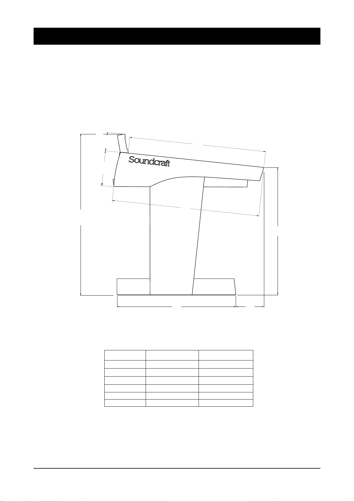
Dimensions
38.87"
987.29mm
mm
4.48"
1130.90
8.37"
212.63mm
903.22mm
35.56"
728.00mm
28.66"
836.75mm
32.94"
171.87mm
6.77"
30.74"
780.81mm
CONSOLE WIDTH WEIGHT
24 ch
24ch + Patchbay
32ch
32ch + Patchbay
40ch
40ch + Patchbay
1368.40mm
1688.00mm
1688.00mm
2007.60mm
2007.60mm
2327.20mm
53.87"
66.46"
66.46"
79.04"
79.04"
91.62"
72kgs
80kgs
80kgs
88kgs
88kgs
96kgs
2.2 DC2020 Installation
158lbs
176lbs
176lbs
194lbs
194lbs
212lbs
Page 13
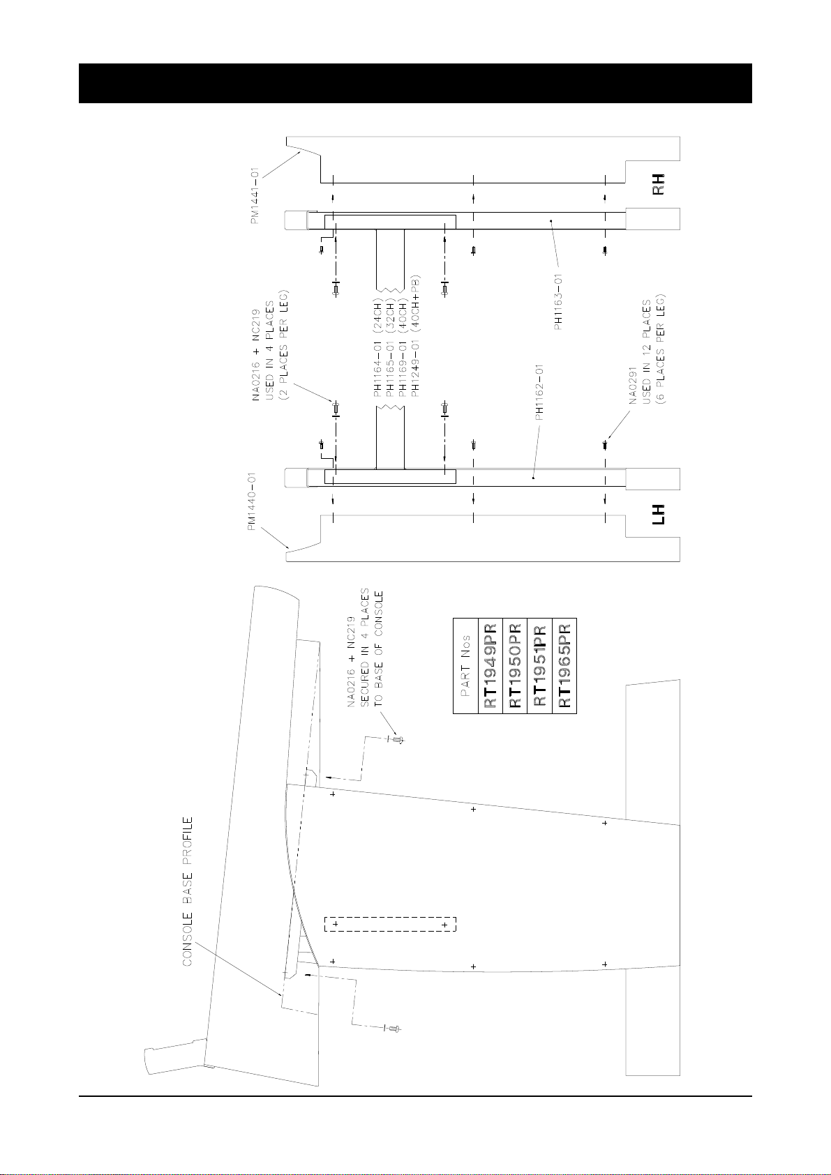
Assembling The Conso le Stand
DC2020 Installation 2.3
Page 14

Precautions and Safety Instructions
General Precautions
Caution!
Handlin g and Tra nsp ort
Power Supplies & cables
Avoid storing or using the mixing console in conditions of excessive heat or cold,
or in positions where it is likely to be subject to vibration, dust or moistu re. Do not
use any liquids to clean the fascia of the unit: a soft dry brush is ideal. Use only
water or e thyl alc ohol to cl ean the t rim and sc ribble strips. Ot her solve nts may cause
dama ge to pa in t or pl a sti c pa rt s.
Avoid using the console close to strong sources of electromagnetic radiation (e.g.
video monitors, highpower electric cabling) : this may cause degradation of the audio
quality due to induced voltages in connecting leads and chassis. For the same
reason, alwa ys sit e the powe r supply awa y from the unit .
In all cases, refer servici ng to qualified per sonnel.
The console is suppli ed in a wooden cra te. If it is ne cessa ry to move it any dista nce
after installation it is recommended that this packing is used to protect it. Be sure
to disco nne ct a ll c ab ling be fo re mo ving. If the con sole i s t o be reg ula rl y mo ved we
recom mend tha t it is inst alle d in a foaml ined fl ightc ase. At al l times av oid ap plying
excessive force to any knobs, switches or co nnectors.
Always make sure that the power supply unit (PSU) has been set to the same voltage
as the mains supply
Signal Levels
Warning!
Always use the power supply and cable supplied with the mixer: the use of
alternative supplies may cause damage and voids the warranty; the extension of
power cabl es m ay re sult in ma lfu nc tion of t he mixin g co nsol e.
Always switch the power supply off before connecting or disconnecting the
mixer powe r cable , rem ovi ng of instal ling module s, and ser vicing. In the ev ent
of an electrical storm, or large mains v oltage fluctuati ons, immediate l y switch
off the PSU and unplug from the mains.
Always ensure that you use the correct PSU for your mixer. The DC2020 uses a
APS500A power supply.
It is important to supply the correct input levels to the console, otherwise signalto
noise ratio or distortion performance may be degraded; and in extreme cases,
dama ge to the inter na l ci rc ui try may resu lt . Likewise, on all bal an ce d i nput s av oid
sources with large commonmode DC, AC or RF voltages, as these will reduce the
availa ble signal range on the inputs. Note that 0dBu = 0.775V RMS.
The microphone inputs are design ed for use with ba l an ced low im pe da nc e (150 or
200 ohms) mic rop hone s.
2.4 DC2020 Installation
Page 15

Caution!
DO NOT use unbalanced microphones or battery powered condenser
microphones without isolating the +48V phantom power: degraded
performa nce or damage to the microphone ma y result.
The sensit ivity of the XLR inputs i s variabl e from -2dBu to -70dBu and + 10dBu to
-20dBu in two range s (for +4dBu at the Mix outputs). The maxi mum inp ut level is
+28dBu.
The Hi-Z inputs have a sensitivity variable between +10dBu and -20dBu. The
maximum input level is +30dBu.
The main outputs of the console (stereo mix, groups, wedge and mix and group
insert sends) are balanced at a nominal level of +4dBu, with a maximum output
level of +26dBu.
The inp ut insert sends a nd dire ct ou tputs a re ground compe nsat ed at a nominal level
of -2dBu, with a maxim um outp ut lev el of +20dB u.
All externa l inputs and m ix and group inse rt returns have a nominal leve l of +4dBu,
and a maximum input leve l of +26dBu .
Input insert returns have a nominal level of -2dBu, and a maximum input level of
+20dBu.
DC2020 Installation 2.5
Page 16

Installation
The DC2020 is designed for reliability and high performance, and is built to the
highest standards. Whilst great care has been taken to ensure that installations are
made as troubl efree as possible, car e taken at this sta ge, followe d by corre ct setting
up will be rewa rd ed by a long l ife and reliable ope ra t ion .
Wiring Considerations
Power Supply (APS520)
Warning!
A For optim um perfor mance it is essent ial for the earthi ng system to be clean and
noisefree, as all signals are referenced to this earth. A central point should be
decided on for the main earth point, and all earths should be ’star-fed’ from this
point. It is recommended that an individual earth wire be run from each electrical
outlet, bac k to the syst em star p oint to pro vide a sa fety e arth refere nce for each piece
of equi pment.
B Install separate mains outlets for the audio equipment, and feed these
indepe nde ntly from any oth er equ ipment.
C Av o id loc a ti ng m a ins d ist rib ution boxes ne a r audi o e qui pm ent, especia ll y ta pe
record er s, whi c h ar e ve ry sensi ti ve to ele c tr om ag ne ti c fi e lds.
D Where possible ensure that all audio cable screens and signal earths are
connect ed to ground on ly at their sou rc e.
Always ensure that you use the correct PSU for your mixer. The DC2020 uses a
APS520 power supply.
Before switching on your DC2020 console, check that the mains voltage selectors
on the power supply unit is set to the correct mains voltage for your area, and that
the fuse is of the corre c t ratin g and typ e. This is cle ar ly m ar ke d on the ca se of the
power suppl y. Do not repl ac e the fuse with any othe r ty pe , as t his c ou ld b ec om e a
safety hazard and will void the warranty.
2.6 DC2020 Installation
Page 17

Connections
Wiring conventions
The DC2020 use s two different types o f audio connec tor: 3-pin XLR and 1⁄4" 3-pole
jacks. The latter are used in seve ral co nfi gura t ion s, as shown below (not e that the
patchbay versions have no 1/4" jack sockets except for the SMPTE In and Out
connections). The DC2020 also uses DIN, D-type and BNC connectors: these are
shown on th e ne xt pa ge .
MICROP HONE INPUT S
1
/4" ‘A ’ Gauge Stereo Jack Plug used as balanced input:
Line Inputs, Stereo Inputs, Tape Inputs, 2-Trk Inputs,
Grou p Inse rts and SMPTE Timecode In
1
/4" ‘A’ Gauge Stereo Jack Plug used as Insert Send/Return Point:
Mono Input Insert , Mix Insert
1
/4" ‘A’ Gauge Stereo Jack Plug used as ground compensat ed output:
Tape Sends, Group Outputs, Aux Outputs, Studio Phones, Studio Speakers ,
FB Outputs, Mix Outputs, Control-room Outputs, Alt Outputs
and SMP TE Timecode Out
1
/4" ‘A’ Gauge Stereo Jack Plug used as stereo output: Headphones
DC2020 Installation 2.7
Page 18
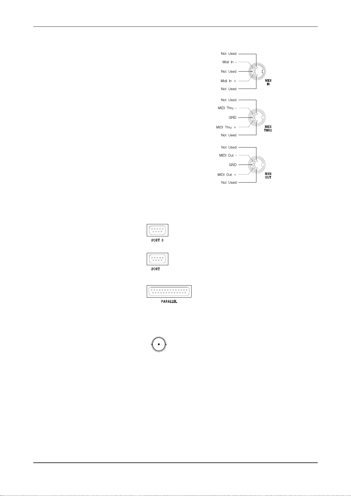
DIN Connectors
The MIDI IN signal is buffered
by an opto-isolator.
MIDI THRU
MIDI OUT
D-Type Connectors
Ports 1, 2 and 4 are not used.
3
5
2
4
1
3
5
2
4
1
3
5
2
4
1
Port 3 conforms to EIA RS-422A . It is used to
connect to Sony 9-pin connectors, see Appendix A
for details.
Female
Port 5 connects to a MAC or a PC for remote emulation
of the Touch Screen. See the next page for details
of the cable required.
5
Male
Female
BNC Connector
Video Sync Input
Centre Pin Standard Composite Video Signal (1v pk-pk 75ohms)
Body Ground
The Parallel Port is an industry-standard
Centronics interface. See Appendix C for
more d etails.
2.8 DC2020 Installation
Page 19

Connecting the DC2020 to a MAC or to a PC
You may connect the DC2020 to either a MAC or a PC to provide touch-screen
emulat ion. In either ca se you will nee d to make or obta in a suita ble connect ing lead.
The conne cti ons re qui re d are shown in the diagr ams be lo w.
DC2020 To MAC Connection
DC2020 To PC Connection
DC2020 Installation 2.9
Page 20

Installing the MAC or PC Emulation Software
Software is provi ded with the DC20 20 which allows the touc h screen of the console
to be used via a comp u ter in te rfa c e . Such sof tware is availab le for eit he r th e PC or
the Macintosh. The software is an emulation of the touch screen but allows use of
a mouse (or other pointing device) and input from the computer keyboard.
Installing the DC2020 Emulation Software
DC for Macintosh
1. From the Fil e Menu selec t new to creat e a new fold er on your hard disk.
2. Clic k on the folder label and change the name of the folder to DC2020.
3. Insert the floppy disk RX3023 into th e di sk dri ve .
4. Doubl e click th e disk icon .
5. Drag the DC2020 icon from the disk window to the DC2020 folder on the
hard dis k.
6. In ord er to run the emulati on softwa re, doubl e click the DC20 20 icon.
On powering up the DC2020 console, an image of the DC2020 touch screen will
appear on the Macin tosh scre e n.
DC for Windows.
1. Run Microsoft Windows.
2. Run File Manager.
3. Insert the floppy disk RX3026 into drive A.
4. Using File Manager copy dcfw.exe from drive A to your hard disk .
5. While in File Manager drag the dcfw.exe filename into a window on your
desktop.
6. In the Progra m Mana ger sel ect File Prope rt ies. ..
i. type DC2020 display in the description box
ii. click OK
7. To run th e emul ati on sof tw are doubl e clic k the DC for Windows icon
8. Once the DC2020 emulation is running, choose Select Port... from the
Settings pull down menu. Selec t the PC port to which your PC-t o-Consol e cable
is connected e.g. port 1.
IMPORTANT:
It is impo rtant t o understa nd th at the Windows / Maci ntosh i nterfa ce is an em ulation
of the DC2020 touch sensitive screen. Therefore, the location of a mouse click on
the computer screen is translated into a press on one or more cells of the touch
sensitive screen.Consequently a touch pad in close proximity to the mouse click
may respon d, even though t he mouse pointer is not strictly wi thin the box. This m ay
run contrary to expectations if one is familiar with Windows or Macintosh
applications.
2.10 DC2020 Installation
Page 21
Patchbay EDAC Pin I dentificati on Chart an d Pinouts
A
D
A
D
A
D
A
KKNN
KKNN
KKNN
KKNN
A
F
A
F
A
F
CW
DB
CW
DB
CW
DB
D
A
D
A
D
A
D
KKNN
KKNN
KKNN
A
F
A
F
A
F
CW
DB
CW
DB
CW
DB
DC2020 Installation 2.11
Page 22

TAPE TRACKS 1-8
A . . . . . . . . . . . . . . . . . TRET+6
B . . . . . . . . . . . . . . . . . TRET-6
C . . . . . . . . . . . . . . . . . GND
D . . . . . . . . . . . . . . . . . TSND+7
E . . . . . . . . . . . . . . . . . TSND-6
F . . . . . . . . . . . . . . . . . GND
H . . . . . . . . . . . . . . . . . GND
J . . . . . . . . . . . . . . . . . GND
K . . . . . . . . . . . . . . . . . TSND-7
L . . . . . . . . . . . . . . . . . TSND+6
M . . . . . . . . . . . . . . . . . GND
N . . . . . . . . . . . . . . . . . TRET-7
P . . . . . . . . . . . . . . . . . TRET+7
h . . . . . . . . . . . . . . . . . . GND
j . . . . . . . . . . . . . . . . . . GND
k . . . . . . . . . . . . . . . . . . TRET+4
l . . . . . . . . . . . . . . . . . . TRET-4
m . . . . . . . . . . . . . . . . . GND
n . . . . . . . . . . . . . . . . . . TSND+1
p . . . . . . . . . . . . . . . . . . TSND-4
r . . . . . . . . . . . . . . . . . . GND
s . . . . . . . . . . . . . . . . . . GND
t . . . . . . . . . . . . . . . . . . TSND-1
u . . . . . . . . . . . . . . . . . . TSND+4
v . . . . . . . . . . . . . . . . . . GND
w . . . . . . . . . . . . . . . . . GND
R . . . . . . . . . . . . . . . . . TRET+5
S . . . . . . . . . . . . . . . . . TRET-5
T . . . . . . . . . . . . . . . . . GND
U . . . . . . . . . . . . . . . . . GND
V . . . . . . . . . . . . . . . . . TSND+8
W . . . . . . . . . . . . . . . . . TSND-5
X . . . . . . . . . . . . . . . . . GND
Y . . . . . . . . . . . . . . . . . GND
Z . . . . . . . . . . . . . . . . . TSND-8
a . . . . . . . . . . . . . . . . . TSND+5
b . . . . . . . . . . . . . . . . . GND
c . . . . . . . . . . . . . . . . . TRET-8
d . . . . . . . . . . . . . . . . . TRET+8
x . . . . . . . . . . . . . . . . . . TRET-1
y . . . . . . . . . . . . . . . . . . TRET+1
z . . . . . . . . . . . . . . . . . . TRET+3
AA . . . . . . . . . . . . . . . . TRET-3
BB . . . . . . . . . . . . . . . . GND
CC . . . . . . . . . . . . . . . . TSND+2
DD . . . . . . . . . . . . . . . . TSND-3
EE . . . . . . . . . . . . . . . . . GND
FF . . . . . . . . . . . . . . . . . GND
HH . . . . . . . . . . . . . . . . GND
JJ . . . . . . . . . . . . . . . . . TSND-2
KK . . . . . . . . . . . . . . . . TSND+3
LL . . . . . . . . . . . . . . . . . GND
e . . . . . . . . . . . . . . . . . GND
f . . . . . . . . . . . . . . . . . GND
MM . . . . . . . . . . . . . . . . TRET-2
NN . . . . . . . . . . . . . . . . TRET+2
2.12 DC2020 Installation
Page 23

TAPE TRACKS 9-16
A . . . . . . . . . . . . . . . . . TRET+14
B . . . . . . . . . . . . . . . . . TRET-14
C . . . . . . . . . . . . . . . . . GND
D . . . . . . . . . . . . . . . . . TSND+15
E . . . . . . . . . . . . . . . . . TSND-14
F . . . . . . . . . . . . . . . . . GND
H . . . . . . . . . . . . . . . . . GND
J . . . . . . . . . . . . . . . . . GND
K . . . . . . . . . . . . . . . . . TSND-15
L . . . . . . . . . . . . . . . . . TSND+14
M . . . . . . . . . . . . . . . . . GND
N . . . . . . . . . . . . . . . . . TRET-15
P . . . . . . . . . . . . . . . . . TRET+15
h . . . . . . . . . . . . . . . . . . GND
j . . . . . . . . . . . . . . . . . . GND
k . . . . . . . . . . . . . . . . . . TRET+12
l . . . . . . . . . . . . . . . . . . TRET-12
m . . . . . . . . . . . . . . . . . GND
n . . . . . . . . . . . . . . . . . . TSND+9
p . . . . . . . . . . . . . . . . . . TSND-12
r . . . . . . . . . . . . . . . . . . GND
s . . . . . . . . . . . . . . . . . . GND
t . . . . . . . . . . . . . . . . . . TSND-9
u . . . . . . . . . . . . . . . . . . TSND+12
v . . . . . . . . . . . . . . . . . . GND
w . . . . . . . . . . . . . . . . . GND
R . . . . . . . . . . . . . . . . . TRET+13
S . . . . . . . . . . . . . . . . . TRET-13
T . . . . . . . . . . . . . . . . . GND
U . . . . . . . . . . . . . . . . . GND
V . . . . . . . . . . . . . . . . . TSND+16
W . . . . . . . . . . . . . . . . . TSND-13
X . . . . . . . . . . . . . . . . . GND
Y . . . . . . . . . . . . . . . . . GND
Z . . . . . . . . . . . . . . . . . TSND-16
a . . . . . . . . . . . . . . . . . TSND+13
b . . . . . . . . . . . . . . . . . GND
c . . . . . . . . . . . . . . . . . TRET-16
d . . . . . . . . . . . . . . . . . TRET+16
x . . . . . . . . . . . . . . . . . . TRET-9
y . . . . . . . . . . . . . . . . . . TRET+9
Z . . . . . . . . . . . . . . . . . TRET+11
AA . . . . . . . . . . . . . . . . TRET-11
BB . . . . . . . . . . . . . . . . GND
CC . . . . . . . . . . . . . . . . TSND+10
DD . . . . . . . . . . . . . . . . TSND-11
EE . . . . . . . . . . . . . . . . . GND
FF . . . . . . . . . . . . . . . . . GND
HH . . . . . . . . . . . . . . . . GND
JJ . . . . . . . . . . . . . . . . . TSND-10
KK . . . . . . . . . . . . . . . . TSND+11
LL . . . . . . . . . . . . . . . . . GND
e . . . . . . . . . . . . . . . . . GND
f . . . . . . . . . . . . . . . . . GND
MM . . . . . . . . . . . . . . . . TRET-10
NN . . . . . . . . . . . . . . . . TRET+10
DC2020 Installation 2.13
Page 24

TAPE TRACKS 17-24
A . . . . . . . . . . . . . . . . . TRET+22
B . . . . . . . . . . . . . . . . . TRET-22
C . . . . . . . . . . . . . . . . . GND
D . . . . . . . . . . . . . . . . . TSND+23
E . . . . . . . . . . . . . . . . . TSND-22
F . . . . . . . . . . . . . . . . . GND
H . . . . . . . . . . . . . . . . . GND
J . . . . . . . . . . . . . . . . . GND
K . . . . . . . . . . . . . . . . . TSND-23
L . . . . . . . . . . . . . . . . . TSND+22
M . . . . . . . . . . . . . . . . . GND
N . . . . . . . . . . . . . . . . . TRET-23
P . . . . . . . . . . . . . . . . . TRET+23
h . . . . . . . . . . . . . . . . . . GND
j . . . . . . . . . . . . . . . . . . GND
k . . . . . . . . . . . . . . . . . . TRET+20
l . . . . . . . . . . . . . . . . . . TRET-20
m . . . . . . . . . . . . . . . . . GND
n . . . . . . . . . . . . . . . . . . TSND+17
p . . . . . . . . . . . . . . . . . . TSND-20
r . . . . . . . . . . . . . . . . . . GND
s . . . . . . . . . . . . . . . . . . GND
t . . . . . . . . . . . . . . . . . . TSND-17
u . . . . . . . . . . . . . . . . . . TSND+20
v . . . . . . . . . . . . . . . . . . GND
w . . . . . . . . . . . . . . . . . GND
R . . . . . . . . . . . . . . . . . TRET+21
S . . . . . . . . . . . . . . . . . TRET-21
T . . . . . . . . . . . . . . . . . GND
U . . . . . . . . . . . . . . . . . GND
V . . . . . . . . . . . . . . . . . TSND+24
W . . . . . . . . . . . . . . . . . TSND-21
X . . . . . . . . . . . . . . . . . GND
Y . . . . . . . . . . . . . . . . . GND
Z . . . . . . . . . . . . . . . . . TSND-24
a . . . . . . . . . . . . . . . . . TSND+21
b . . . . . . . . . . . . . . . . . GND
c . . . . . . . . . . . . . . . . . TRET-24
d . . . . . . . . . . . . . . . . . TRET+24
x . . . . . . . . . . . . . . . . . . TRET-17
y . . . . . . . . . . . . . . . . . . TRET+17
z . . . . . . . . . . . . . . . . . . TRET+19
AA . . . . . . . . . . . . . . . . TRET-19
BB . . . . . . . . . . . . . . . . GND
CC . . . . . . . . . . . . . . . . TSND+18
DD . . . . . . . . . . . . . . . . TSND-19
EE . . . . . . . . . . . . . . . . . GND
FF . . . . . . . . . . . . . . . . . GND
HH . . . . . . . . . . . . . . . . GND
JJ . . . . . . . . . . . . . . . . . TSND-18
KK . . . . . . . . . . . . . . . . TSND+19
LL . . . . . . . . . . . . . . . . . GND
e . . . . . . . . . . . . . . . . . GND
f . . . . . . . . . . . . . . . . . GND
MM . . . . . . . . . . . . . . . . TRET-18
NN . . . . . . . . . . . . . . . . TRET+18
2.14 DC2020 Installation
Page 25

TAPE TRACKS 25-32
A . . . . . . . . . . . . . . . . . TRET+30
B . . . . . . . . . . . . . . . . . TRET-30
C . . . . . . . . . . . . . . . . . GND
D . . . . . . . . . . . . . . . . . TSND+31
E . . . . . . . . . . . . . . . . . TSND-30
F . . . . . . . . . . . . . . . . . GND
H . . . . . . . . . . . . . . . . . GND
J . . . . . . . . . . . . . . . . . GND
K . . . . . . . . . . . . . . . . . TSND-31
L . . . . . . . . . . . . . . . . . TSND+30
M . . . . . . . . . . . . . . . . . GND
N . . . . . . . . . . . . . . . . . TRET-31
P . . . . . . . . . . . . . . . . . TRET+31
h . . . . . . . . . . . . . . . . . . GND
j . . . . . . . . . . . . . . . . . . GND
k . . . . . . . . . . . . . . . . . . TRET+28
l . . . . . . . . . . . . . . . . . . TRET-28
m . . . . . . . . . . . . . . . . . GND
n . . . . . . . . . . . . . . . . . . TSND+25
p . . . . . . . . . . . . . . . . . . TSND-28
r . . . . . . . . . . . . . . . . . . GND
s . . . . . . . . . . . . . . . . . . GND
t . . . . . . . . . . . . . . . . . . TSND-25
u . . . . . . . . . . . . . . . . . . TSND+28
v . . . . . . . . . . . . . . . . . . GND
w . . . . . . . . . . . . . . . . . GND
R . . . . . . . . . . . . . . . . . TRET+29
S . . . . . . . . . . . . . . . . . TRET-29
T . . . . . . . . . . . . . . . . . GND
U . . . . . . . . . . . . . . . . . GND
V . . . . . . . . . . . . . . . . . TSND+32
W . . . . . . . . . . . . . . . . . TSND-29
X . . . . . . . . . . . . . . . . . GND
Y . . . . . . . . . . . . . . . . . GND
Z . . . . . . . . . . . . . . . . . TSND-32
a . . . . . . . . . . . . . . . . . TSND+29
b . . . . . . . . . . . . . . . . . GND
c . . . . . . . . . . . . . . . . . TRET-32
d . . . . . . . . . . . . . . . . . TRET+32
x . . . . . . . . . . . . . . . . . . TRET-25
y . . . . . . . . . . . . . . . . . . TRET+25
z . . . . . . . . . . . . . . . . . . TRET+27
AA . . . . . . . . . . . . . . . . TRET-27
BB . . . . . . . . . . . . . . . . GND
CC . . . . . . . . . . . . . . . . TSND+26
DD . . . . . . . . . . . . . . . . TSND-27
EE . . . . . . . . . . . . . . . . . GND
FF . . . . . . . . . . . . . . . . . GND
HH . . . . . . . . . . . . . . . . GND
JJ . . . . . . . . . . . . . . . . . TSND-26
KK . . . . . . . . . . . . . . . . TSND+27
LL . . . . . . . . . . . . . . . . . GND
e . . . . . . . . . . . . . . . . . GND
f . . . . . . . . . . . . . . . . . GND
MM . . . . . . . . . . . . . . . . TRET-26
NN . . . . . . . . . . . . . . . . TRET+26
DC2020 Installation 2.15
Page 26

TAPE TRACKS 33-40
A . . . . . . . . . . . . . . . . . TRET+38
B . . . . . . . . . . . . . . . . . TRET-38
C . . . . . . . . . . . . . . . . . GND
D . . . . . . . . . . . . . . . . . TSND+39
E . . . . . . . . . . . . . . . . . TSND-38
F . . . . . . . . . . . . . . . . . GND
H . . . . . . . . . . . . . . . . . GND
J . . . . . . . . . . . . . . . . . GND
K . . . . . . . . . . . . . . . . . TSND-39
L . . . . . . . . . . . . . . . . . TSND+38
M . . . . . . . . . . . . . . . . . GND
N . . . . . . . . . . . . . . . . . TRET-39
P . . . . . . . . . . . . . . . . . TRET+39
h . . . . . . . . . . . . . . . . . . GND
j . . . . . . . . . . . . . . . . . . GND
k . . . . . . . . . . . . . . . . . . TRET+36
l . . . . . . . . . . . . . . . . . . TRET-36
m . . . . . . . . . . . . . . . . . GND
n . . . . . . . . . . . . . . . . . . TSND+33
p . . . . . . . . . . . . . . . . . . TSND-36
r . . . . . . . . . . . . . . . . . . GND
s . . . . . . . . . . . . . . . . . . GND
t . . . . . . . . . . . . . . . . . . TSND-33
u . . . . . . . . . . . . . . . . . . TSND+36
v . . . . . . . . . . . . . . . . . . GND
w . . . . . . . . . . . . . . . . . GND
R . . . . . . . . . . . . . . . . . TRET+37
S . . . . . . . . . . . . . . . . . TRET-37
T . . . . . . . . . . . . . . . . . GND
U . . . . . . . . . . . . . . . . . GND
V . . . . . . . . . . . . . . . . . TSND+40
W . . . . . . . . . . . . . . . . . TSND-37
X . . . . . . . . . . . . . . . . . GND
Y . . . . . . . . . . . . . . . . . GND
Z . . . . . . . . . . . . . . . . . TSND-40
a . . . . . . . . . . . . . . . . . TSND+37
b . . . . . . . . . . . . . . . . . GND
c . . . . . . . . . . . . . . . . . TRET-40
d . . . . . . . . . . . . . . . . . TRET+40
x . . . . . . . . . . . . . . . . . . TRET-33
y . . . . . . . . . . . . . . . . . . TRET+33
z . . . . . . . . . . . . . . . . . . TRET+35
AA . . . . . . . . . . . . . . . . TRET-35
BB . . . . . . . . . . . . . . . . GND
CC . . . . . . . . . . . . . . . . TSND+34
DD . . . . . . . . . . . . . . . . TSND-35
EE . . . . . . . . . . . . . . . . . GND
FF . . . . . . . . . . . . . . . . . GND
HH . . . . . . . . . . . . . . . . GND
JJ . . . . . . . . . . . . . . . . . TSND-34
KK . . . . . . . . . . . . . . . . TSND+35
LL . . . . . . . . . . . . . . . . . GND
e . . . . . . . . . . . . . . . . . GND
f . . . . . . . . . . . . . . . . . GND
MM . . . . . . . . . . . . . . . . TRET-34
NN . . . . . . . . . . . . . . . . TRET+34
2.16 DC2020 Installation
Page 27

AUX & FOLDBACK O/P, STEREO I/P, STUDIO PHONES
A . . . . . . . . . . . . . . . . . STL+3
B . . . . . . . . . . . . . . . . . STL-3
C . . . . . . . . . . . . . . . . . GND
D . . . . . . . . . . . . . . . . . STL+1
E . . . . . . . . . . . . . . . . . STR-3
F . . . . . . . . . . . . . . . . . GND
H . . . . . . . . . . . . . . . . . GND
J . . . . . . . . . . . . . . . . . GND
K . . . . . . . . . . . . . . . . . STL-1
L . . . . . . . . . . . . . . . . . STR+3
M . . . . . . . . . . . . . . . . . GND
N . . . . . . . . . . . . . . . . . STR-1
P . . . . . . . . . . . . . . . . . STR+1
h . . . . . . . . . . . . . . . . . . GND
j . . . . . . . . . . . . . . . . . . GND
k . . . . . . . . . . . . . . . . . . AUX+1
l . . . . . . . . . . . . . . . . . . AUX-1
m . . . . . . . . . . . . . . . . . GND
n . . . . . . . . . . . . . . . . . . FB+1
p . . . . . . . . . . . . . . . . . . AUX-2
r . . . . . . . . . . . . . . . . . . GND
s . . . . . . . . . . . . . . . . . . GND
t . . . . . . . . . . . . . . . . . . FB-1
u . . . . . . . . . . . . . . . . . . AUX+2
v . . . . . . . . . . . . . . . . . . GND
w . . . . . . . . . . . . . . . . . GND
R . . . . . . . . . . . . . . . . . STL+4
S . . . . . . . . . . . . . . . . . STL-4
T . . . . . . . . . . . . . . . . . GND
U . . . . . . . . . . . . . . . . . GND
V . . . . . . . . . . . . . . . . . STL+2
W . . . . . . . . . . . . . . . . . STR-4
X . . . . . . . . . . . . . . . . . GND
Y . . . . . . . . . . . . . . . . . GND
Z . . . . . . . . . . . . . . . . . STL-2
a . . . . . . . . . . . . . . . . . STR+4
b . . . . . . . . . . . . . . . . . GND
c . . . . . . . . . . . . . . . . . STR-2
d . . . . . . . . . . . . . . . . . STR+2
x . . . . . . . . . . . . . . . . . . FB-2
y . . . . . . . . . . . . . . . . . . FB+2
z . . . . . . . . . . . . . . . . . . AUX+3
AA . . . . . . . . . . . . . . . . AUX-3
BB . . . . . . . . . . . . . . . . GND
CC . . . . . . . . . . . . . . . . SPHL+
DD . . . . . . . . . . . . . . . . AUX-4
EE . . . . . . . . . . . . . . . . . GND
FF . . . . . . . . . . . . . . . . . GND
HH . . . . . . . . . . . . . . . . GND
JJ . . . . . . . . . . . . . . . . . SPHL-
KK . . . . . . . . . . . . . . . . AUX+4
LL . . . . . . . . . . . . . . . . . GND
e . . . . . . . . . . . . . . . . . GND
f . . . . . . . . . . . . . . . . . GND
MM . . . . . . . . . . . . . . . . SPHR-
NN . . . . . . . . . . . . . . . . SPHR+
DC2020 Installation 2.17
Page 28

CONTROL-ROOM O/P, MIX O/P, 2TRACK I/P, STUDIO SPEAKERS, ALT SPEAKERS
A . . . . . . . . . . . . . . . . . 2TBSL+
B . . . . . . . . . . . . . . . . . 2TBSL-
C . . . . . . . . . . . . . . . . . GND
D . . . . . . . . . . . . . . . . . MIXL+
E . . . . . . . . . . . . . . . . . 2TBSR-
F . . . . . . . . . . . . . . . . . GND
H . . . . . . . . . . . . . . . . . GND
J . . . . . . . . . . . . . . . . . GND
K . . . . . . . . . . . . . . . . . MIXL-
L . . . . . . . . . . . . . . . . . 2TBSR+
M . . . . . . . . . . . . . . . . . GND
N . . . . . . . . . . . . . . . . . MIXR-
P . . . . . . . . . . . . . . . . . MIXR+
h . . . . . . . . . . . . . . . . . . GND
j . . . . . . . . . . . . . . . . . . GND
k . . . . . . . . . . . . . . . . . . CRML+
l . . . . . . . . . . . . . . . . . . CRML-
m . . . . . . . . . . . . . . . . . GND
n . . . . . . . . . . . . . . . . . . SSPL+
p . . . . . . . . . . . . . . . . . . CRMR-
r . . . . . . . . . . . . . . . . . . GND
s . . . . . . . . . . . . . . . . . . GND
t . . . . . . . . . . . . . . . . . . SSPL-
u . . . . . . . . . . . . . . . . . . CRMR+
v . . . . . . . . . . . . . . . . . . GND
w . . . . . . . . . . . . . . . . . GND
R . . . . . . . . . . . . . . . . . 2TAL+
S . . . . . . . . . . . . . . . . . 2TAL-
T . . . . . . . . . . . . . . . . . GND
U . . . . . . . . . . . . . . . . . GND
V . . . . . . . . . . . . . . . . . 2TASL+
W . . . . . . . . . . . . . . . . . 2TAR-
X . . . . . . . . . . . . . . . . . GND
Y . . . . . . . . . . . . . . . . . GND
Z . . . . . . . . . . . . . . . . . 2TASL-
a . . . . . . . . . . . . . . . . . 2TAR+
b . . . . . . . . . . . . . . . . . GND
c . . . . . . . . . . . . . . . . . 2TASR-
d . . . . . . . . . . . . . . . . . 2TASR+
x . . . . . . . . . . . . . . . . . . SSPR-
y . . . . . . . . . . . . . . . . . . SSPR+
z . . . . . . . . . . . . . . . . . . 2TBL+
AA . . . . . . . . . . . . . . . . 2TBL-
BB . . . . . . . . . . . . . . . . GND
CC . . . . . . . . . . . . . . . . ALTL+
DD . . . . . . . . . . . . . . . . 2TBR-
EE . . . . . . . . . . . . . . . . . GND
FF . . . . . . . . . . . . . . . . . GND
HH . . . . . . . . . . . . . . . . GND
JJ . . . . . . . . . . . . . . . . . ALTL-
KK . . . . . . . . . . . . . . . . 2TBR+
LL . . . . . . . . . . . . . . . . . GND
e . . . . . . . . . . . . . . . . . GND
f . . . . . . . . . . . . . . . . . GND
MM . . . . . . . . . . . . . . . . ALTR-
NN . . . . . . . . . . . . . . . . ALTR+
2.18 DC2020 Installation
Page 29

LINE INPUTS 1-24
A . . . . . . . . . . LINE1+
B . . . . . . . . . . LINE1-
C . . . . . . . . . . GND
D . . . . . . . . . . GND
E . . . . . . . . . . LINE13-
F . . . . . . . . . . LINE13+
H . . . . . . . . . . LINE2+
J . . . . . . . . . . LINE2-
K . . . . . . . . . . GND
L . . . . . . . . . . GND
M . . . . . . . . . . GND
N . . . . . . . . . . LINE14-
P . . . . . . . . . . LINE14+
AK . . . . . . . . LINE17-
AL . . . . . . . . . LINE17+
AM . . . . . . . . LINE6+
AN . . . . . . . . LINE6-
AP . . . . . . . . . GND
AR . . . . . . . . . GND
AS . . . . . . . . . GND
AT . . . . . . . . . LINE18-
AU . . . . . . . . LINE18+
AV . . . . . . . . GND
AW . . . . . . . . GND
AX . . . . . . . . GND
AY . . . . . . . . GND
BU . . . . . . . . . GND
BV . . . . . . . . . GND
BW . . . . . . . . . LINE20-
BX . . . . . . . . . LINE20+
BY . . . . . . . . . LINE9+
BZ . . . . . . . . . LINE9-
CA . . . . . . . . . GND
CB . . . . . . . . . GND
CC . . . . . . . . . GND
CD . . . . . . . . . LINE21-
CE . . . . . . . . . LINE21+
CF . . . . . . . . . LINE10+
CH . . . . . . . . . LINE10-
R . . . . . . . . . . LINE3+
S . . . . . . . . . . LINE3-
T . . . . . . . . . . GND
U . . . . . . . . . . GND
V . . . . . . . . . . LINE15-
W . . . . . . . . . . LINE15+
X . . . . . . . . . . LINE4+
Y . . . . . . . . . . LINE4-
Z . . . . . . . . . . GND
AA . . . . . . . . . GND
AB . . . . . . . . . GND
AC . . . . . . . . . LINE16-
AD . . . . . . . . . LINE16+
AZ . . . . . . . . . GND
BA . . . . . . . . . GND
BB . . . . . . . . . GND
BC . . . . . . . . . GND
BD . . . . . . . . . GND
BE . . . . . . . . . GND
BF . . . . . . . . . GND
BH . . . . . . . . . GND
BJ . . . . . . . . . LINE7+
BK . . . . . . . . . LINE7-
BL . . . . . . . . . GND
BM . . . . . . . . GND
BN . . . . . . . . . GND
CJ . . . . . . . . . . GND
CK . . . . . . . . . GND
CL . . . . . . . . . LINE22-
CM . . . . . . . . . LINE22+
CN . . . . . . . . . LINE11+
CP . . . . . . . . . LINE11-
CR . . . . . . . . . GND
CS . . . . . . . . . GND
CT . . . . . . . . . GND
CU . . . . . . . . . LINE23-
CV . . . . . . . . . LINE23+
CW . . . . . . . . . LINE12+
CX . . . . . . . . . LINE12-
AE . . . . . . . . . LINE5+
AF . . . . . . . . . LINE5-
AH . . . . . . . . . GND
AJ . . . . . . . . . GND
BP . . . . . . . . . LINE19-
BR . . . . . . . . . LINE19+
BS . . . . . . . . . LINE8+
BT . . . . . . . . . LINE8-
CY . . . . . . . . . GND
CZ . . . . . . . . . GND
DA . . . . . . . . . LINE24-
DB . . . . . . . . . LINE24+
DC2020 Installation 2.19
Page 30

TIE LINES 1-24
A . . . . . . . . . . T-LINE1+
B . . . . . . . . . . T-LINE1-
C . . . . . . . . . . GND
D . . . . . . . . . . GND
E . . . . . . . . . . T-LINE13-
F . . . . . . . . . . T-LINE13+
H . . . . . . . . . . T-LINE2+
J . . . . . . . . . . T-LINE2-
K . . . . . . . . . . GND
L . . . . . . . . . . GND
M . . . . . . . . . . GND
N . . . . . . . . . . T-LINE14-
P . . . . . . . . . . T-LINE14+
AK . . . . . . . . T-LINE17-
AL . . . . . . . . . T-LINE17+
AM . . . . . . . . T-LINE6+
AN . . . . . . . . T-LINE6-
AP . . . . . . . . . GND
AR . . . . . . . . . GND
AS . . . . . . . . . GND
AT . . . . . . . . . T-LINE18-
AU . . . . . . . . T-LINE18+
AV . . . . . . . . GND
AW . . . . . . . . GND
AX . . . . . . . . GND
AY . . . . . . . . GND
BU . . . . . . . . . GND
BV . . . . . . . . . GND
BW . . . . . . . . . T-LINE20-
BX . . . . . . . . . T-LINE20+
BY . . . . . . . . . T-LINE9+
BZ . . . . . . . . . T-LINE9-
CA . . . . . . . . . GND
CB . . . . . . . . . GND
CC . . . . . . . . . GND
CD . . . . . . . . . T-LINE21-
CE . . . . . . . . . T-LINE21+
CF . . . . . . . . . T-LINE10+
CH . . . . . . . . . T-LINE10-
R . . . . . . . . . . T-LINE3+
S . . . . . . . . . . T-LINE3-
T . . . . . . . . . . GND
U . . . . . . . . . . GND
V . . . . . . . . . . T-LINE15-
W . . . . . . . . . . T-LINE15+
X . . . . . . . . . . T-LINE4+
Y . . . . . . . . . . T-LINE4-
Z . . . . . . . . . . GND
AA . . . . . . . . . GND
AB . . . . . . . . . GND
AC . . . . . . . . . T-LINE16-
AD . . . . . . . . . T-LINE16+
AZ . . . . . . . . . GND
BA . . . . . . . . . GND
BB . . . . . . . . . GND
BC . . . . . . . . . GND
BD . . . . . . . . . GND
BE . . . . . . . . . GND
BF . . . . . . . . . GND
BH . . . . . . . . . GND
BJ . . . . . . . . . T-LINE7+
BK . . . . . . . . . T-LINE7-
BL . . . . . . . . . GND
BM . . . . . . . . GND
BN . . . . . . . . . GND
CJ . . . . . . . . . . GND
CK . . . . . . . . . GND
CL . . . . . . . . . T-LINE22-
CM . . . . . . . . . T-LINE22+
CN . . . . . . . . . T-LINE11+
CP . . . . . . . . . T-LINE11-
CR . . . . . . . . . GND
CS . . . . . . . . . GND
CT . . . . . . . . . GND
CU . . . . . . . . . T-LINE23-
CV . . . . . . . . . T-LINE23+
CW . . . . . . . . . T-LINE12+
CX . . . . . . . . . T-LINE12-
AE . . . . . . . . . T-LINE5+
AF . . . . . . . . . T-LINE5-
AH . . . . . . . . . GND
AJ . . . . . . . . . GND
BP . . . . . . . . . T-LINE19-
BR . . . . . . . . . T-LINE19+
BS . . . . . . . . . T-LINE8+
BT . . . . . . . . . T-LINE8-
CY . . . . . . . . . GND
CZ . . . . . . . . . GND
DA . . . . . . . . . T-LINE24-
DB . . . . . . . . . T-LINE24+
2.20 DC2020 Installation
Page 31

TIE LINES 25-48
A . . . . . . . . . . T-LINE25+
B . . . . . . . . . . T-LINE25-
C . . . . . . . . . . GND
D . . . . . . . . . . GND
E . . . . . . . . . . T-LINE37-
F . . . . . . . . . . T-LINE37+
H . . . . . . . . . . T-LINE26+
J . . . . . . . . . . T-LINE26-
K . . . . . . . . . . GND
L . . . . . . . . . . GND
M . . . . . . . . . . GND
N . . . . . . . . . . T-LINE38-
P . . . . . . . . . . T-LINE38+
AK . . . . . . . . T-LINE41-
AL . . . . . . . . . T-LINE41+
AM . . . . . . . . T-LINE30+
AN . . . . . . . . T-LINE30-
AP . . . . . . . . . GND
AR . . . . . . . . . GND
AS . . . . . . . . . GND
AT . . . . . . . . . T-LINE42-
AU . . . . . . . . T-LINE42+
AV . . . . . . . . GND
AW . . . . . . . . GND
AX . . . . . . . . GND
AY . . . . . . . . GND
BU . . . . . . . . . GND
BV . . . . . . . . . GND
BW . . . . . . . . . T-LINE44-
BX . . . . . . . . . T-LINE44+
BY . . . . . . . . . T-LINE33+
BZ . . . . . . . . . T-LINE33-
CA . . . . . . . . . GND
CB . . . . . . . . . GND
CC . . . . . . . . . GND
CD . . . . . . . . . T-LINE45-
CE . . . . . . . . . T-LINE45+
CF . . . . . . . . . T-LINE34+
CH . . . . . . . . . T-LINE34-
R . . . . . . . . . . T-LINE27+
S . . . . . . . . . . T-LINE27-
T . . . . . . . . . . GND
U . . . . . . . . . . GND
V . . . . . . . . . . T-LINE39-
W . . . . . . . . . . T-LINE39+
X . . . . . . . . . . T-LINE28+
Y . . . . . . . . . . T-LINE28-
Z . . . . . . . . . . G ND
AA . . . . . . . . . GND
AB . . . . . . . . . GND
AC . . . . . . . . . T-LINE40-
AD . . . . . . . . . T-LINE40+
AZ . . . . . . . . . GND
BA . . . . . . . . . GND
BB . . . . . . . . . GND
BC . . . . . . . . . GND
BD . . . . . . . . . GND
BE . . . . . . . . . GND
BF . . . . . . . . . GND
BH . . . . . . . . . GND
BJ . . . . . . . . . T-LINE31+
BK . . . . . . . . . T-LINE31-
BL . . . . . . . . . GND
BM . . . . . . . . GND
BN . . . . . . . . . GND
CJ . . . . . . . . . . GND
CK . . . . . . . . . GND
CL . . . . . . . . . T-LINE 46-
CM . . . . . . . . . T-LINE46+
CN . . . . . . . . . T-LINE35+
CP . . . . . . . . . T-LINE35-
CR . . . . . . . . . GND
CS . . . . . . . . . GND
CT . . . . . . . . . GND
CU . . . . . . . . . T-LINE47-
CV . . . . . . . . . T-LINE47+
CW . . . . . . . . . T-LINE36+
CX . . . . . . . . . T-LINE36-
AE . . . . . . . . . T-LINE29+
AF . . . . . . . . . T-LINE29-
AH . . . . . . . . . GND
AJ . . . . . . . . . GND
BP . . . . . . . . . T-LINE43-
BR . . . . . . . . . T-LINE43+
BS . . . . . . . . . T-LINE32+
BT . . . . . . . . . T-LINE32-
CY . . . . . . . . . GND
CZ . . . . . . . . . GND
DA . . . . . . . . . T-LINE48-
DB . . . . . . . . . T-LINE48+
DC2020 Installation 2.21
Page 32

TIE LINES 49-72
A . . . . . . . . . . T-LINE49+
B . . . . . . . . . . T-LINE49-
C . . . . . . . . . . GND
D . . . . . . . . . . GND
E . . . . . . . . . . T-LINE61-
F . . . . . . . . . . T-LINE61+
H . . . . . . . . . . T-LINE50+
J . . . . . . . . . . T-LINE50-
K . . . . . . . . . . GND
L . . . . . . . . . . GND
M . . . . . . . . . . GND
N . . . . . . . . . . T-LINE62-
P . . . . . . . . . . T-LINE62+
AK . . . . . . . . T-LINE65-
AL . . . . . . . . . T-LINE65+
AM . . . . . . . . T-LINE54+
AN . . . . . . . . T-LINE54-
AP . . . . . . . . . GND
AR . . . . . . . . . GND
AS . . . . . . . . . GND
AT . . . . . . . . . T-LINE66-
AU . . . . . . . . T-LINE66+
AV . . . . . . . . GND
AW . . . . . . . . GND
AX . . . . . . . . GND
AY . . . . . . . . GND
BU . . . . . . . . . GND
BV . . . . . . . . . GND
BW . . . . . . . . . T-LINE68-
BX . . . . . . . . . T-LINE68+
BY . . . . . . . . . T-LINE57+
BZ . . . . . . . . . T-LINE57-
CA . . . . . . . . . GND
CB . . . . . . . . . GND
CC . . . . . . . . . GND
CD . . . . . . . . . T-LINE69-
CE . . . . . . . . . T-LINE69+
CF . . . . . . . . . T-LINE58+
CH . . . . . . . . . T-LINE58-
R . . . . . . . . . . T-LINE51+
S . . . . . . . . . . T-LINE51-
T . . . . . . . . . . GND
U . . . . . . . . . . GND
V . . . . . . . . . . T-LINE63-
W . . . . . . . . . . T-LINE63+
X . . . . . . . . . . T-LINE52+
Y . . . . . . . . . . T-LINE52-
Z . . . . . . . . . . GND
AA . . . . . . . . . GND
AB . . . . . . . . . GND
AC . . . . . . . . . T-LINE64-
AD . . . . . . . . . T-LINE64+
AZ . . . . . . . . . GND
BA . . . . . . . . . GND
BB . . . . . . . . . GND
BC . . . . . . . . . GND
BD . . . . . . . . . GND
BE . . . . . . . . . GND
BF . . . . . . . . . GND
BH . . . . . . . . . GND
BJ . . . . . . . . . T-LINE55+
BK . . . . . . . . . T-LINE55-
BL . . . . . . . . . GND
BM . . . . . . . . GND
BN . . . . . . . . . GND
CJ . . . . . . . . . . GND
CK . . . . . . . . . GND
CL . . . . . . . . . T-LINE70-
CM . . . . . . . . . T-LINE70+
CN . . . . . . . . . T-LINE59+
CP . . . . . . . . . T-LINE59-
CR . . . . . . . . . GND
CS . . . . . . . . . GND
CT . . . . . . . . . GND
CU . . . . . . . . . T-LINE71-
CV . . . . . . . . . T-LINE71+
CW . . . . . . . . . T-LINE60+
CX . . . . . . . . . T-LINE60-
AE . . . . . . . . . T-LINE53+
AF . . . . . . . . . T-LINE53-
AH . . . . . . . . . GND
AJ . . . . . . . . . GND
BP . . . . . . . . . T-LINE67-
BR . . . . . . . . . T-LINE67+
BS . . . . . . . . . T-LINE56+
BT . . . . . . . . . T-LINE56-
CY . . . . . . . . . GND
CZ . . . . . . . . . GND
DA . . . . . . . . . T-LINE72-
DB . . . . . . . . . T-LINE72+
2.22 DC2020 Installation
Page 33

TIE LINES 73-96
A . . . . . . . . . . T-LINE73+
B . . . . . . . . . . T-LINE73-
C . . . . . . . . . . GND
D . . . . . . . . . . GND
E . . . . . . . . . . T-LINE85-
F . . . . . . . . . . T-LINE85+
H . . . . . . . . . . T-LINE74+
J . . . . . . . . . . T-LINE74-
K . . . . . . . . . . GND
L . . . . . . . . . . GND
M . . . . . . . . . . GND
N . . . . . . . . . . T-LINE86-
P . . . . . . . . . . T-LINE86+
AK . . . . . . . . T-LINE89-
AL . . . . . . . . . T-LINE89+
AM . . . . . . . . T-LINE78+
AN . . . . . . . . T-LINE78-
AP . . . . . . . . . GND
AR . . . . . . . . . GND
AS . . . . . . . . . GND
AT . . . . . . . . . T-LINE90-
AU . . . . . . . . T-LINE90+
AV . . . . . . . . GND
AW . . . . . . . . GND
AX . . . . . . . . GND
AY . . . . . . . . GND
BU . . . . . . . . . GND
BV . . . . . . . . . GND
BW . . . . . . . . . T-LINE92-
BX . . . . . . . . . T-LINE92+
BY . . . . . . . . . T-LINE81+
BZ . . . . . . . . . T-LINE81-
CA . . . . . . . . . GND
CB . . . . . . . . . GND
CC . . . . . . . . . GND
CD . . . . . . . . . T-LINE93-
CE . . . . . . . . . T-LINE93+
CF . . . . . . . . . T-LINE82+
CH . . . . . . . . . T-LINE82-
R . . . . . . . . . . T-LINE75+
S . . . . . . . . . . T-LINE75-
T . . . . . . . . . . GND
U . . . . . . . . . . GND
V . . . . . . . . . . T-LINE87-
W . . . . . . . . . . T-LINE87+
X . . . . . . . . . . T-LINE76+
Y . . . . . . . . . . T-LINE76-
Z . . . . . . . . . . GND
AA . . . . . . . . . GND
AB . . . . . . . . . GND
AC . . . . . . . . . T-LINE88-
AD . . . . . . . . . T-LINE88+
AZ . . . . . . . . . GND
BA . . . . . . . . . GND
BB . . . . . . . . . GND
BC . . . . . . . . . GND
BD . . . . . . . . . GND
BE . . . . . . . . . GND
BF . . . . . . . . . GND
BH . . . . . . . . . GND
BJ . . . . . . . . . T-LINE79+
BK . . . . . . . . . T-LINE79-
BL . . . . . . . . . GND
BM . . . . . . . . GND
BN . . . . . . . . . GND
CJ . . . . . . . . . . GND
CK . . . . . . . . . GND
CL . . . . . . . . . T-LINE94-
CM . . . . . . . . . T-LINE94+
CN . . . . . . . . . T-LINE83+
CP . . . . . . . . . T-LINE83-
CR . . . . . . . . . GND
CS . . . . . . . . . GND
CT . . . . . . . . . GND
CU . . . . . . . . . T-LINE95-
CV . . . . . . . . . T-LINE95+
CW . . . . . . . . . T-LINE84+
CX . . . . . . . . . T-LINE84-
AE . . . . . . . . . T-LINE77+
AF . . . . . . . . . T-LINE77-
AH . . . . . . . . . GND
AJ . . . . . . . . . GND
BP . . . . . . . . . T-LINE91-
BR . . . . . . . . . T-LINE91+
BS . . . . . . . . . T-LINE80+
BT . . . . . . . . . T-LINE80-
CY . . . . . . . . . GND
CZ . . . . . . . . . GND
DA . . . . . . . . . T-LINE96-
DB . . . . . . . . . T-LINE96+
DC2020 Installation 2.23
Page 34

TIE LINES 97-120
A . . . . . . . . . . T-LINE97+
B . . . . . . . . . . T-LINE97-
C . . . . . . . . . . GND
D . . . . . . . . . . GND
E . . . . . . . . . . T-LINE109-
F . . . . . . . . . . T-LINE109+
H . . . . . . . . . . T-LINE98+
J . . . . . . . . . . T-LINE98-
K . . . . . . . . . . GND
L . . . . . . . . . . GND
M . . . . . . . . . . GND
N . . . . . . . . . . T-LINE110-
P . . . . . . . . . . T-LINE110+
AK . . . . . . . . T-LINE113-
AL . . . . . . . . . T-LINE113+
AM . . . . . . . . T-LINE102+
AN . . . . . . . . T-LINE102-
AP . . . . . . . . . GND
AR . . . . . . . . . GND
AS . . . . . . . . . GND
AT . . . . . . . . . T-LINE114-
AU . . . . . . . . T-LINE114+
AV . . . . . . . . GND
AW . . . . . . . . GND
AX . . . . . . . . GND
AY . . . . . . . . GND
BU . . . . . . . . . GND
BV . . . . . . . . . GND
BW . . . . . . . . . T-LINE116-
BX . . . . . . . . . T-LINE116+
BY . . . . . . . . . T-LINE105+
BZ . . . . . . . . . T-LINE105-
CA . . . . . . . . . GND
CB . . . . . . . . . GND
CC . . . . . . . . . GND
CD . . . . . . . . . T-LINE117-
CE . . . . . . . . . T-LINE117+
CF . . . . . . . . . T-LINE106+
CH . . . . . . . . . T-LINE106-
R . . . . . . . . . . T-LINE99+
S . . . . . . . . . . T-LINE99-
T . . . . . . . . . . GND
U . . . . . . . . . . GND
V . . . . . . . . . . T-LINE111-
W . . . . . . . . . . T-LINE111+
X . . . . . . . . . . T-LINE100+
Y . . . . . . . . . . T-LINE100-
Z . . . . . . . . . . GND
AA . . . . . . . . . GND
AB . . . . . . . . . GND
AC . . . . . . . . . T-LINE112-
AD . . . . . . . . . T-LINE112+
AZ . . . . . . . . . GND
BA . . . . . . . . . GND
BB . . . . . . . . . GND
BC . . . . . . . . . GND
BD . . . . . . . . . GND
BE . . . . . . . . . GND
BF . . . . . . . . . GND
BH . . . . . . . . . GND
BJ . . . . . . . . . T-LINE103+
BK . . . . . . . . . T-LINE103-
BL . . . . . . . . . GND
BM . . . . . . . . GND
BN . . . . . . . . . GND
CJ . . . . . . . . . . GND
CK . . . . . . . . . GND
CL . . . . . . . . . T-LINE118-
CM . . . . . . . . . T-LINE118+
CN . . . . . . . . . T-LINE107+
CP . . . . . . . . . T-LINE107-
CR . . . . . . . . . GND
CS . . . . . . . . . GND
CT . . . . . . . . . GND
CU . . . . . . . . . T-LINE119-
CV . . . . . . . . . T-LINE119+
CW . . . . . . . . . T-LINE108+
CX . . . . . . . . . T-LINE108-
AE . . . . . . . . . T-LINE101+
AF . . . . . . . . . T-LINE101-
AH . . . . . . . . . GND
AJ . . . . . . . . . GND
BP . . . . . . . . . T-LINE115-
BR . . . . . . . . . T-LINE115+
BS . . . . . . . . . T-LINE104+
BT . . . . . . . . . T-LINE104-
CY . . . . . . . . . GND
CZ . . . . . . . . . GND
DA . . . . . . . . . T-LINE120-
DB . . . . . . . . . T-LINE120+
2.24 DC2020 Installation
Page 35

Block Diagrams
DC2020 Block Diagrams 3.1
Page 36

Mono Input
3.2 DC2020 Block Diagrams
Page 37
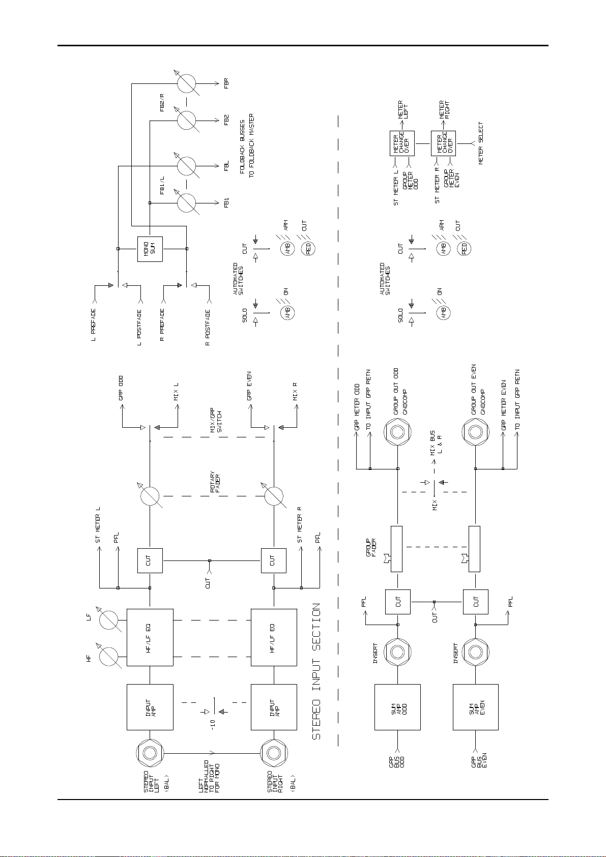
Stereo Input/Groups
DC2020 Block Diagrams 3.3
Page 38

Aux Master
3.4 DC2020 Block Diagrams
Page 39

Studio, Foldback and Oscillator/Talkback
DC2020 Block Diagrams 3.5
Page 40

Mix and Control Room Monitor
3.6 DC2020 Block Diagrams
Page 41

Functional Descriptions
DC2020 Functional Descriptions 4.1
Page 42

4.2 DC2020 Functional Descriptions
Page 43

Mono Inputs
DC2020 Mono Inputs 4.3
Page 44

Mono Input
1
2
3
4
9
12
15
16
19
22
5
6
7
8
10
11
13
14
17
18
20
21
23
Input Control Section
1
If the +48V switch is depressed then +48V phantom power is supplied to the
rear-panel Mic XLR socket
2
When the LINE switch is released the input to the channel is via the Mic XLR
socket; when the LINE switch is depressed the input is via the 1/4"Line soc ket
The input sensitivity is -40dBu to +10dBu for Line input and -60dBu to -10 dBu
for Mic input.
3
The gain of the input amplifier is controlled by the INPUT Gain pot., the gain
range is +10db to +60dB.
4
The ∅ (Phase) button reverses the phase of the input signal.
5
The input amplifier is followed by a 100Hz high-pass filter. This is switched in
or out of the circuit by the 100Hz switch: when the switch is depressed the filter is
in circuit.
Tape Return
The electronically balanced tape return is switchable, via a switch which is
accessible on the underside of the console, between nominal levels of +4dBu and
-10dBV.
6
The Tape Return Trim control has a gain range of +/-10dB.
24
25
26
27
28
27
29
31
30
32
36
33
35
34
7
The Monitor Source switch (MON SRC) selec ts eithe r the Ta pe Re turn or the
Tape Send as the monitor source. When the switch is released the Tape Return is
the monitor source.
8
The Tape Source switch (TAPE SRC) selects either the Channel post-fade
signal direct (DIR) or the Group Return signal as the Tape Send source. When the
switch is released the direct signal is used as th e Tape Send source. When the switch
is depressed the Group Return is the source. The Groups Returns feed the Channels
as follows:
Group 1 - Channels 1,9,17,25,33.
Group 2 - Channels 2,10,18,26,34.
Group 3 - Channels 3,11,19,27,35.
Group 4 - Channels 4,12,20,28,36.
Group 5 - Channels 5,13,21,29,37.
Group 6 - Channels 6,14,22,30,38.
Group 7 - Channels 7,15,23,31,39.
Group 8 - Channels 8,16,24,32,40.
4.4 DC2020 Mono Inputs
Page 45

1
2
Note: Channels 25-40 may not be present on your console .
EQ
The EQ is split into two parts. The first part is the HF/LF EQ, this consists of two
equalisers which may be independently configured as shelving or bell-response
filters.
4
9
12
15
16
19
3
5
6
7
8
10
11
13
14
17
18
20
21
The HF Bell/Shelf switch configures the HF EQ. The bell-response Q factor is
9
1.5 .
The HF Cut/Boost control provides a cut and boost of +/-15dB.
10
The HF Frequency control, which is calibrated from 500Hz to 16kHz, sets the
11
shelving frequency cut-off point (-3dB) or the peak frequency, depending upon
whether shelving or bell response has been selected.
The LF Bell/Shelf switch configures the LF EQ. The bell-response Q factor is
12
1.3 .
The LF Cut/Boost control provides a cut and boost of +/-15dB.
13
The LF Frequency control, which is calibrated from 50Hz to 1.6kHz, sets the
14
shelving frequency cut-off point (-3dB) or the peak frequency, depending upon
whether shelving or bell response has been selected.
The HF/LF EQ can be switched into the Channel signal path or the Monitor
15
signal path via the MON switch: when the switch is depressed the HF/LF EQ is
placed in the Monitor signal path.
22
23
24
25
26
27
28
27
29
31
30
32
36
33
The second part is the HI MID/LO MID EQ. This consists of two bell-response
equalisers. Each of these may be set one of two Q-factors.
The Hi Mid Lo Q/Hi Q switch switches the Q factor between 1.2 and 2.0 .
16
The Hi Mid Cut/Boost control provides a cut and boost of +/-15dB.
17
The Hi Mid Frequency control, which is calibrated from 500Hz to 16kHz, sets
18
the peak frequency.
The Lo Mid Lo Q/Hi Q switch switches the Q factor between 1.2 and 2.0 .
19
The Lo Mid Cut/Boost control provides a cut and boost of +/-15dB.
20
The Lo Mid Frequency control, which is calibrated from 50Hz to 1. 6kHz, sets
21
the peak frequency.
The HI MID/LO MID EQ can be switched into the Channel signal path or the
22
Monitor signal path via the MON switch: when the switch is depressed the HI
MID/LO MID EQ is placed in the Monitor signal path.
35
34
DC2020 Mono Inputs 4.5
The EQ IN switch will, when depressed, switch both EQ sections into their
23
selected paths. When the switch is released neither EQ sec tions are in their respective
paths. This switch does not affect the Insert Point.
Page 46

20
19
22
21
23
24
25
26
27
28
27
29
31
30
Note: the Insert Point (via rearcon panel, or patchbay if fitted) is placed after the
HF/LF EQ and is switched, with this EQ section, between the Channel path and the
Monitor path, via the HF/LF EQ’s EQ TO MON switch.
Auxiliary Controls
The AUX1 Level control is permanently connected to the Monitor path and is
24
post the Monitor Cut and the Monitor Fader.
The Aux1 ON switch is a soft switch, i.e. this switch provides an input to the
25
Automation. The Automation, in turn, controls the ON LED (green), the Arm LED
(amber) and switches the signal from the Aux1 level c ontro l to the Aux1 bus .
The green ON LED glows when the channel’s Aux1 signa l is being fed to the Aux1
bus.
The AUX2 Level control is permanently connected to the Monitor path and is
26
post the Monitor Cut and the Monitor Fader.
The AUX3 and AUX4 level controls are switchable (together) between the
27
Monitor and the Channel paths. Both Aux3 and Aux4 feeds are connected to the
Channel path when the CHAN switch is depressed.
37
42
47
32
36
33
35
34
38
43
39
40
41
44
45
46
48
49
For either path, the Aux3 and Aux4 feeds are taken post the Cut and the Fader of
the relevant path.
The Aux3 ON switch is a soft switch, i.e. this switch provides an input to the
28
Automation. The Automation, in turn, controls the ON LED (green), the Arm LED
(amber) and switches the signal from the Aux3 level c ontro l to the Aux3 bus .
The green ON LED glows when the channel’s Aux3 signa l is being fed to the Aux3
bus.
Foldback
The Foldback 1 Level Control, marked as FB1/L CH/MON, sends two signals
29
to the Foldback Masters & Studio Outputs PCB, as follows:
1 The Channel pre-fade or post-fade signal (depending upon the position of the
POST switch,see below).
2 The Monitor pre-fade or post-fade signal (depending upon the position of the
POST switch,see below).
The Foldback 1 Control may therefore be used for the Channel path signals or the
Monitor Path signals. Its use is controlled by the CH/MON switch which is located
on the Foldback Masters & Studio Outputs panel (see the Foldback Masters &
Studio Outputs section for more details).
The Foldback 2 Level Control, marked as FB2/R MON, sends the Monitor
30
pre-fade or post-fade signal (depending upon the position of the POST switch,see
below) to the Foldback Masters & Studio Outputs PCB.
Note. The FB1 and FB2 signals may be used as the Left and Right channels of a
stereo Foldback signal. This feature is also controlled by the Foldback Masters &
Studio Outputs panel, via a switch labelled STEREO (see the Foldback Masters &
Studio Outputs chapter for more details).
4.6 DC2020 Mono Inputs
Page 47

20
19
22
21
23
24
25
26
27
28
When the POST switch is depressed, both the FB1 and FB2 paths are fed
31
post-fade; when the POST switch is released the signals are pre-fade.
Pan Control
The MON PAN control positions the Monitor signal within the stereo image
32
carried by the MONL and MONR buses. These buses connect with the Mix Le ft &
Right board where they are summed with signals carried by the MIXL and MIXR
buses, and also summed with Talkback sign als (see the Stereo Master chapter for
more details).
The CHAN P AN control positions the Channel post-fade signal within a stereo
33
image. This stereo image may be connected to the MIXL and MIXR buses, and also
to the Group buses (1-8) by the use of the Routing switches (see Routing section
below).
37
42
47
27
29
31
30
32
36
33
35
34
38
43
39
40
41
44
45
46
48
49
Routing
Normally the post-fade, post-pan Channel signal is sent to the routing matrix.
34
This matrix is controlled by the switches marked, 1-2, 3-4, 5-6 and 7-8. When, for
example, the switch marked, 1-2 is depressed, the post-fade, post-pan Channel
signal is fed onto the Group 1 bus and the Group 2 bus. The Group 1 bus carries the
Left image from the Channel Pan control, whilst the Group 2 bus carries the Right
image from the Channel Pan control. Similarly for the remaining 3 matrix switches ,
the odd numbered Groups carry the Left image and the even numbered Groups carry
the Right image.
The Group buses may be used to route the signal from one input channel to the tape
send of a different channel.
The stereo image may also be connected to the MIXL and MIXR buses, this is
35
done by depressing the MIX switch.
When the BOUNCE switch is depressed, the routing matrix is disconnected
36
from the Channel path and is, instead, connected to the Monitor path. This allows
the Group buses to be used for track bouncing.
Channel Path
The non-motorised Channel Fader feeds the CHAN PAN control and also
37
normally feeds the Tape Send. It may also be switched to feed Aux3 & Aux4, and
FB1
A multi-point peak detector illuminates the CHAN PEAK LED when less than
38
6dB of headroom remains at two critical places in the signa l path: the Input preamp
and the pre-fade connection to the Channel Fader.
The Channel SOLO switch is a soft switch, i.e. this switch provides an input
39
to the Automation. The Automation , in turn, passes the Channel signal onto the
PFL bus and also switches the input of the Control-room/Headphones (CRM/PH)
circuit from its selected input to the PFL bus.
The Automation also indicates, by switching on the ass ociated SOLO LED, that the
Solo is active on the Channel.
The Automation gives the Solo switch a toggle action: note that the switch itself
does not physically latch.
DC2020 Mono Inputs 4.7
Page 48

20
19
22
21
23
The Channel CUT switch is a soft switch, i.e. this switch provides an input to
40
the Automation. The Automation , in turn, controls the Cut circuit and also the
Channel CUT and Arm LEDs
The REC LED indicates when the tape machine is in record mode for the trac k
41
which is connected to this channel.
24
25
26
27
28
27
29
31
30
32
36
33
35
34
Monitor Path
The motorised Monitor Fader feeds the MON PAN control, it also feeds the
42
Aux1 and Aux2 Level controls and normally feeds the Aux3 and Aux4 Level
controls. It may also be switched to feed the FB1MON and FB2 buses.
A multi-point peak detector illuminates the MON PEAK LED when les s tha n
43
6dB of headroom remains at two critical places in the signal path: the Monitor
Source switch and the pre-fade connection to the Monitor Fader.
The Monitor SOLO switch is a soft switch, i.e. this switch provides an input to
44
the Automation. The Automation , in turn, passes the Monitor signal onto the PFL
bus and also switches the input of the Control-room/Headphones circuit from its
selected input to the PFL bus.
The Automation also indicates, by switching on the ass ociated SOLO LED, that the
Solo is active on the Monitor.
The Automation gives the Solo switch a toggle action: note that the switch itself
does not physically latch.
The Monitor CUT switch is a soft switch, i.e. this switch provides an input to
45
the Automation. The Automation , in turn, controls the Cut circuit and also the
Monitor CUT and Arm LEDs
37
42
47
38
43
39
40
41
44
45
46
48
49
The SEL switch is a soft switch, i.e. this switch provides an input to the
46
Automation. This switch has three functions.
Firstly, it is used to arm the Aux1, Aux3, Channel Cut and Monitor Cut switches.
To Arm one of these switches, you press and hold the SEL switch and then press
the CUT or Aux ON switch in question, then release both switches.
Secondly, it is used in conjunction with the Group Assignments pag. This allows
you to assign channels to Control Groups, see page 4.71.
Finally, if the RECORD ENABLE or PREVIEW modes are selected (via the c ontrol
panel keyboard) the SEL button may be used to Record Enable the tape track in
question. The REC LED indicates when this has happened.
Automated Fader and Switch Modes
Each Automated Fader and Switches can be in one of four modes, which are as
follows:
Manual.. The Fader or Switch operates normally as if it were not automate d.
Read. Changes to the Fader or Switches which have previously been recorded
against the Timecode are played back, i.e. the changes are rea d from the Automation.
Armed. This mode is the same as Read mode until you make a change, at which
point the change(s) are written into the Mix Data.
4.8 DC2020 Mono Inputs
Page 49

20
19
22
21
23
24
25
26
27
Write. If the Fader is moved or a Switch is pressed this is written into the Mix Data,
creating a new Mix, or writing over any previous Mix data.
The mode of a Fader or Switch is changed by pressing the appropriate mode
47
switch, labelled SW for Switches and FDR for the Fader. Pressing the Mode s witch
causes the mode to be cycled through in the following sequence: Manual, Read,
Armed and Write. Note that Manual Mode is not a vailable whilst the Tape is running
with Mix on.
The WR (Write) and RD (Read) LEDs indicate which mode the Fader and
48
Switches are currently in. There are separate LEDs on each channel for Fader and
Switches. The modes are indicated as follows:
RD WR
37
28
27
29
31
30
32
36
33
35
34
38
43
39
40
41
44
45
Manual: OFF OFF
Read: ON OFF
Armed: ON ON
Write: OFF ON
The Control Group Assigned LEDs (CNTR GRP ASN) indicate which Control
49
Group, if any, each Input Channel is assigned to.
The Solo System
The Solo System works in two ways.
Solo
In Solo mode (the SIP LED on the Master Panel will be off) the Solo switches on
both the Channel and Monitor sections behave as Pre-fa de Listens ,i.e. they feed the
PFL signal to the Headphones./Control Room Output.
Solo In Place
In Solo-In-Place mode (the SIP LED on the Master Panel will be on) the Solo
switches on both the Channel and Monitor sections will mute a ll othe r Channe l or
Monitor sections respectively.
Any of the Channels or Monitors may be Solo-In-Place protected (safed) so that
they are not muted by other solo switches. This is done via the Monitor SIP Safe
and Channel SIP Safe pages.
46
42
48
47
49
DC2020 Mono Inputs 4.9
Meters
The Meter may be used to monitor the Channel (send) or the Monitor (return)
section. The meters are switchable in groups of eight inputs . They are switched via
the Meterbridge Set-up page. The current setting is indicated by the SEND and
RETURN LEDs on the overbridge.
Page 50

Rear Connector Panel
Microphone Input - Female XLR
Pin 1 Screen
Pin 2 Hot (in phase signal)
Pin 3 Cold (out of phase signal
The Patchbay version does not have the following connectors on the Input Rear
Connector Panel: see the Patchbay section of this chapter, and the EDAC
connector pin lists in chapter2, for details.
Line Input - 3-pole Jack
Tip Hot (in pha se signa l)
Ring Cold (out of phase signal)
Sleeve Ground
Insert
Tip Return
Ring Send
Sleeve Ground
Tape Return
Tip Hot (in pha se signa l)
Ring Cold (out of phase signal)
Sleeve Ground
Tape Send
Tip Hot (in pha se signa l)
Ring Cold (out of phase signal)
Sleeve Ground
4.10 DC2020 Mono Inputs
Page 51

Group/Stereo Input
DC2020 Group/Stereo Input 4.11
Page 52
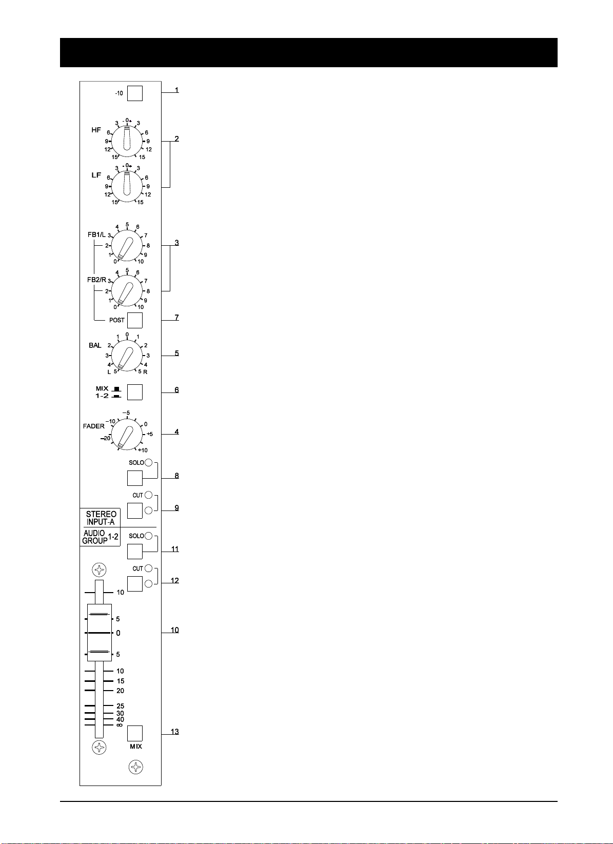
Group/Stereo Input
Stereo Input
1
The -10 switch changes the nominal input level from +4dBu, when the switch
is released, to -10dBV, when the switch is depressed.
EQ
2
The stereo 2-band shelving EQ has a +/-15dB cut and boost at 3kHz, which is
controlled by the HF control, and a +/-15dB cut and boost at 150Hz, which is
controlled by the LF control.
Routing
3
The output of the EQ section is normally fed to the Foldback level controls,
marked FB1/L and FB2/R. The FB1/L control sends the Left stereo signal to the
FBL bus and also a mono (L+R) signal to the FB1S bus. The FB2/R control sends
the Right stereo signal to the FBR bus and also a mono (L+R) to the FB2S bus.
These buses are connected to the Foldback Master & Studio Outputs pan el.
4
The output of the EQ section is also fed to the Rotary FADER. The Fader has
a max. gain of +10dB. It is advisable to turn this fader fully off (anti-clockwise) if
the Stereo Input in question is not being used.
5
The Fader feeds the BALance control, which adjusts the relative levels of the
Left and Right stereo image.
6
The output of the Balance control normally feeds the MIXL and MIXR bus es ,
via the MIX switch; the output of the Balance control is switched over to a pair of
Group buses when the MIX switch is depressed: the Group buses are identified on
the panel legend, under the word, ’MIX’.
7
The Foldback level controls are fed post-fade when the POST switch is
depressed.
8
The SOLO switch is a soft switch, i.e. this switch provides an input to the
Automation. The Automation , in turn, controls the PFL circuit, which switches a
mono (L+R) signal onto the PFL bus. The adjacent LED illuminates when the PFL
circuit is active on any particular Stereo Input panel.
The Automation also activates the PFL circuit in the Control-room Phones/Sp eakers
Panel: this feeds the Signal from the Stereo Input to the Control-room
Phones/Speakers.
9
The CUT switch is a soft switch, i.e. this switch provides an input to the
Automation. The Automation, in turn, controls the Cut circuit, which is post-fade.
GROUP
The 8 Group buses are processed in pairs. There are, therefore, four Group panels.
The pair of Groups which each panel controls is marked on the panel.
The Group buses have two functions. The first is to allow you to route a sign al from
an Input Channel to a different numbered Tape send. The second is to allow track
4.12 DC2020 Group/Stereo Input
Page 53

bouncing.
Only one of the pair of signals is considered here.
The summed Group signal is passed through an unbalanced Ins ert point on the rear
connector panel.
The Insert-point Return signal is fed to the Fader, which provides a gain of
10
+10dB at the top of its travel.
The Insert-point Return signal is also fed to an electro nic PFL switch. The input
11
to this switch is the sum of both of the Group pair signals. The PFL switch is
controlled by the Automation. The Automation reads the state of the SOLO switch
to decide when to activate the electronic PFL switch. When the PFL is active, the
LED adjacent to the SOLO switch is illuminated. The PFL signal is sent to the
Control-room Phones/Speakers.
The post-fade signal is fed to an electronic cut switc h. This switch is controlled
12
by the Automation in response to the soft CUT switch. The adjacent LED illuminated when the CUT is active.
The post-cut signal is fed to its appropriate Group Return bus. The eight Group
Return buses in the console facilitate the connection of any Input Channel to any
Tape Send, and they are also used when track bouncing.
The post-cut signal is also fed, via the MIX switch, to the MIXL bus (odd-num-
13
bered Groups) or the MIXR bus (even-numbered Groups ); these buses are the Stereo
Master Mix buses.
The post-cut signal is also fed to an output socket on the rearcon panel.
Meters
The Metering consists of twin 16-LED bargraph meters. They may be connected to
the pre-fade section of the Stereo Inputs or to the post-fade, post-cut section of the
Groups. The switching is under the control of the Automation: they are switched
via the Meterbridge Set-up page. The current setting is indicated by the STE and
GRP LEDs on the overbridge.
DC2020 Group/Stereo Input 4.13
Page 54

Rear Connector Panel
(Non-Patchbay Only)
Stereo Input
The stereo inputs are electronically balanced. The left input is normalled to the right
input on the rear panel Jack sockets: if only a mono signal is available it is
automatically routed to both Left and Right signal paths. Plugging a Jack plug into
the Right socket disconnects the normalling.
Tip Hot (in pha se signa l)
Ring Cold (out of phase signal)
Sleeve Ground
Groups
Group Inserts
Tip Return
Ring Send
Sleeve Ground
Group Outputs - 3-pole Jack
The Group outputs are ground compensated. This provides a very effective way
of optimising noise immunity, without the complexity of balanced outputs. Ground
compensated outputs cancel the effects of va riation in ground potential betwe en the
mixer and other equipment which would otherwise show up as hum.
If the output is driving an amplifier that has an unbalanced input, connect the -ive
(cold) signal to the ground at the destination, not at the output of the console.
Tip Hot (in pha se signa l)
Ring Cold (ground sense)
Sleeve Ground
4.14 DC2020 Group/Stereo Input
Page 55

Auxiliary Master
DC2020 Auxiliary Master 4.15
Page 56

Auxiliary Master
There are four auxiliary buses. Each Input Module is able to put sig nals on e ach of
the four Aux buses. Aux1 & Aux2 are only fed from the Monitor path, post-fade.
Aux3 & Aux4 may be fed from The Channel path or the Monitor path, both
post-fade.
Auxiliary 1
The signal level from the Aux1 summing amp is controlled by the AUX1 pot.
1
The AFL switch causes the post-pot, post-cut signal to be sent to the Control-
2
room PFL/AFL system.
The CUT switch is a soft switch, i.e. this switch provides an input to the
3
Automation. The Automation , in turn, controls the electronic Cut circ uit, wh ich is
post-pot. The Automation also controls the adjacent CUT and ARM LEDS ( red
and amber respectively).
Auxiliary 2
The signal level from the Aux2 summing amp is controlled by the AUX2 pot.
4
The AFL switch causes the post-pot, post-cut signal to be sent to the Control-
5
room PFL/AFL system.
The CUT switch is a soft switch, i.e. this switch provides an input to the
6
Automation. The Automation , in turn, controls the electronic Cut circ uit, wh ich is
post-pot. The Automation also controls the adjacent CUT and ARM LEDS ( red
and amber respectively).
Auxiliary 3
The signal level from the Aux3 summing amp is controlled by the AUX3 pot.
7
The AFL switch causes the post-pot, post-cut signal to be sent to the Control-
8
room PFL/AFL system.
The CUT switch is a soft switch, i.e. this switch provides an input to the
9
Automation. The Automation , in turn, controls the electronic Cut circ uit, wh ich is
post-pot. The Automation also controls the adjacent CUT and ARM LEDS ( red
and amber respectively).
The AUX3 TO AUX1 switch, connects the Aux3 post-pot, post-cut signal to
10
the Aux1 Master signal path, at a point which is post the Aux1 Cut circuit.
Auxiliary 4
The signal level from the Aux4 summing amp is controlled by the AUX4 pot.
11
The AFL switch causes the post-pot, post-cut signal to be sent to the Control-
12
room PFL/AFL system.
4.16 DC2020 Auxiliary Master
Page 57

The CUT switch is a soft switch, i.e. this switch provides an input to the
13
Automation. The Automation , in turn, controls the electronic Cut circ uit, wh ich is
post-pot. The Automation also controls the adjacent CUT and Arm LEDS ( red and
amber respectively).
The AUX4 TO AUX2 switch, connects the Aux4 post-pot, post-cut signal to
14
the Aux2 Master signal path, at a point which is post the Aux2 Cut circuit.
Rear Connector Panel
(Non-Patchbay Only)
Aux OUT 1 to AUX OUT 4 - 3-pole Jack
The Aux outputs are ground compensated. This provides a very effective way of
optimising noise immunity, without the complexity of balanced outputs. Ground
compensated outputs cancel the effects of va riation in ground potential betwe en the
mixer and other equipment which would otherwise show up as hum.
If the output is driving an amplifier that has an unbalanced input, connect the -ive
(cold) signal to the ground at the destination, not at the output of the console.
The connections are:
Tip Hot (in pha se signa l)
Ring Cold (ground sense)
Sleeve Ground
DC2020 Auxiliary Master 4.17
Page 58

4.18 DC2020 Auxiliary Master
Page 59

Studio Outputs & FB Masters
DC2020 Studio Outputs & FB Masters 4.19
Page 60

Studio Outputs & Foldback Masters
Studio Outputs
The signal level available at the Studio Speakers Output jacks on the rearcon
1
panel is controlled by the C/RM TO STUDIO SPKRS pot. The input to this control
is taken from the source selector switches on the Control-room Speakers/Phones
Panel.
When the Talkback-to-Speakers signal (from the Talkback Panel) is present, the
normal signal is dimmed and the Talkback signal is supe rimposed. The leve l of the
Talkback signal is not affected by the setting of the C/RM TO STUDIO SPKRS
control, it is set by the GAIN control on the TALKBACK Panel.
The signal level available at the Studio Headphones Output jacks on the rearcon
2
panel is controlled by the C/RM TO PHNS pot. The input to this control is taken
from the source selector switches on the Control-room Speakers/Phones Panel.
The FB1 switch adds in the Foldback 1 post-fade signal to the Studio Phones
3
post-pot signal (both Left and Right signals of the Headphone stereo image).
Similarly, the FB2 switch adds in the Foldback 2 signal to the post-pot signal.
4
Both of these switches, FB1 and FB2, may be depressed at the same time. If,
however the STEREO switch on the Foldback panel is depressed then the FB1
signal is only sent to the Left channel, whilst the FB2 signal is only sent to the Right
channel.
These signals are then passed through the STUDIO PHNS level control.
5
When the Talkback-to-Phones signal (from the Talkback Panel) is present, the
normal signal is dimmed and the Talkback signal is supe rimposed. The leve l of the
Talkback signal is not affected by the setting of the STUDIO PHNS control, it is set
by the GAIN control on the TALKBACK Panel.
The AFL switch sends a mono (L+R) signal to the PFL/AFL circuit of the
6
Control-room Monitor. Its associated LED indicates when the s witch is depressed.
Foldback Masters
The Foldback system has 2 channels: FB1 and FB2. These are controlled by the
section described below.
The Foldback Master section receives inputs from two Module types: the Input
Modules and the Stereo Input Modules.
Signals from Input Modules
The FB1 signal is switchable between the Channel and the Monitor path. The
7
switching is done by the CH/MON switch. The level of the FB1 signal from each
Input Module is controlled by the FB1/L CH/MON pot on each Input Module .
The FB2 signal is always connected to the M oni tor p ath, its l evel f rom each Input
Module is controlled by the FB2/R MON pot on each Input Module.
Both of the FB1 and FB2 signals described above are available pre -fade or post-fade
4.20 DC2020 Studio Outputs & FB Masters
Page 61

from each Input Module: they are both switched (together) by the POST switch on
each Input Module.
Signals from Stereo Input Modules
8
When the STEREO switch is released, Mono signals (L+R) from the Stereo
Input channels are connected to both the FB1 and the FB2 channels. The level of
the signal from each of the Stereo Inputs is controlled by the FB1/L and FB2/R leve l
controls on each of the Stereo Inputs.
When the STEREO switch is depressed, the Left signals from the Stereo inputs are
connected to the FB1 channel and the Right signals are connected to the FB2
channel. Again, the level from each of the Stereo inputs is controlled by the FB1/L
and FB2/R level controls.
Note: When the STEREO switch is depressed it is recommended that the CH/MON
switch is also depressed.
Note: The Foldback Master panel mixes the signals from all of the Input Modules
and the Stereo Input Modules. The relative level of each depends upon the setting
of the Level control on each individual module.
9
After mixing the Foldback signals are fed through their respective faders,
FB1/L and FB2/R.
From this point in the description only one of the two Foldback channels will be
described.
10
After the fader there is an electronic cut switch. This is controlled by the
Automation. The Automation also reads the state of the CUT switch, and controls
the state of the adjacent CUT LED and the ARM LED.
The Automation Operates the Cut as follows:
11
The AFL switch connects the post-fade post-cut signal to PFL/AFL bus. The
position of this switch is also read by the Automation: the Automation switches the
Control-room Phones/Speakers to listen to the PFL signal.
DC2020 Studio Outputs & FB Masters 4.21
Page 62

Rear Connector Panel
(Non-Patchbay Only)
The Studio and Foldback outputs are ground compensated. This provides a very
effective way of optimising noise immunity, without the complexity of balanced
outputs. Ground compensated outputs cancel the effects of variation in ground
potential between the mixer and other equipment which would otherwise show up
as hum.
If the output is driving an amplifier that has an unbalanced input, connect the -ive
(cold) signal to the ground at the destination, not at the output of the console.
FB1
Tip Hot (in pha se signa l)
Ring Cold (ground sense)
Sleeve Ground
FB2
Tip Hot (in pha se signa l)
Ring Cold (ground sense)
Sleeve Ground
Studio Phones L
Tip Hot (in pha se signa l)
Ring Cold (ground sense)
Sleeve Ground
Studio Phones R
Tip Hot (in pha se signa l)
Ring Cold (ground sense)
Sleeve Ground
Studio Speakers L
Tip Hot (in pha se signa l)
Ring Cold (ground sense)
Sleeve Ground
Studio Speakers R
Tip Hot (in pha se signa l)
Ring Cold (ground sense)
Sleeve Ground
4.22 DC2020 Studio Outputs & FB Masters
Page 63

Oscillator & Talkback Panel
DC2020 Oscillator & Talkback Panel 4.23
Page 64

Oscillator and Talkback Panel
Power Indicators
There are four LEDs which indicate the pres ence of power on power rails within
1
the machine. They are 48V, 17V, 12V and 5V
Oscillator
The Oscillator is used to set signal levels at the tape machine. This oscillator isn’t
to be confused with the Slate Oscillator which is used for marking the tape.
The sine wave oscillator is switchable between 1kHz and 10kHz.
2
The OSC control adjusts the level of the oscillator signal: it has a ma ximum of
3
10VU.
Pressing the CAL switch fixes the level at 0dBu at the mix output, this level is
4
adjustable via the preset pot which is accessible through the small hole near the OSC
pot.
The TAPE switch routes the oscillator signal to the SLATE bus and also
5
activates the Slate Enable (SLATEN) bus: this causes all the Input Modules to switch
their Tape Sends to the Oscillator signal. The MIX switch adds the Oscillator signal
to the MIXL and MIXR buses. The LED between the TAPE and MIX buttons glows
if either of these switches are pressed.
Talkback
The Talkback system includes the Slate Oscillator: the nominal frequency of the
tape oscillator is 25Hz.
The GAIN pot controls the amplification of the inbuilt mic Talkback Ampli-
6
fier.
The inbuilt microphone.
7
When the TAPE switch is pressed the Slate Oscillator is switched on. Its output
8
is summed with the output of the Talkback Amplifier. The summed output signal
is routed to the SLATE bus and is also summed with the MIXL and MIXR buses;
the routing is done via the TAPE and MIX switches in the Oscillator section, so
pressing either of these will override the talkback to their respective destinations.
The SLATEN bus is also activated: this causes a ll the Input Modules to switch their
Tape Sends to the Slate Oscillator + Talkback signal.
The Control-room phones/speakers signals are attenuate d by a nominal 20dB when
the TAPE switch is pressed.
When the Talkback to STUDIO SPeaKeRS switch is pressed the signals to
9
Studio Speakers are attenuated by 20dB (nominal) and the talkback signal from the
in-built mic is added to the attenuated signal.
The Control-room phones/speakers signals are also attenuated by a nominal 20dB
when the STUDIO SPEAKERS switch is pressed.
4.24 DC2020 Oscillator & Talkback Panel
Page 65

When the Talkback to STUDIO PHONES switch is pressed the signals to the
10
Studio Phones are attenuated by 20dB (nominal) and the talkback signal from the
in-built mic is added to the attenuated signal.
The Control-room phones/speakers signals are also attenuated by a nominal 20dB
when the STUDIO PHONES switch is pressed.
DC2020 Oscillator & Talkback Panel 4.25
Page 66

4.26 DC2020 Oscillator & Talkback Panel
Page 67

Control Groups
DC2020 Control Groups 4.27
Page 68

Control Groups
There are four Control Groups. Each Mono Input strip may be assigned to one of
the Control Groups at a time, or assigned to none of them.
Channel
Pressing the SOLO switch will put all of the Channels of the Mono Inputs which
1
are assigned to this particular Control Group into Solo mode: the solo mode will be
either Solo or Solo-in-place, depending upon the status of the SIP switch on the
Stereo Master panel.
Pressing the UNCUT switch will release any Cut Channels on Mono Inputs
2
which are assigned to the Control Group in question.
Pressing the CUT switch will Cut any Channels on Mono Inputs which are
3
assigned to the Control Group in question.
Note: the Uncut and Cut functions are momentary and do not force the state of the
assigned channels after they have been pressed.
Monitor
Pressing the SOLO switch will put all of the Monitors of the Mono Inputs which
4
are assigned to this particular Control Group into Solo mode: the solo mode will be
either Solo or Solo-in-place, depending upon the status of the SIP switch on the
Stereo Master panel.
Pressing the UNCUT switch will release any cut Monitors on Mono Inputs
5
which are assigned to the Control Group in question.
Pressing the CUT switch will Cut any Monitors on Mono Inputs which are
6
assigned to the Control Group in question.
Note: the Uncut and Cut functions are momentary and do not force the state of the
assigned monitors after they have been pressed.
Fader Disengage
The SEL switch is used to temporarily disengage the Control Group fader:
7
press and hold the SEL button on the appropriate Control Group panel, and move
the fader to a new position, then release the SEL button.
4.28 DC2020 Control Groups
Page 69

Switch and Fader Modes
The mode of the Switches or Faders on all of the assigned Mono Inputs is
8
changed by pressing the appropriate mode switch, labelled SW for Switches and
FDR for the Fader. Pressing the Mode switch causes the mode to be cycled through
in the following sequence: Manual, Read, Armed and Write. Note that Manual Mode
is not available whilst the Tape is running. with Mix on
The WR (Write) and RD (Read) LEDs indicate which mode the a ssigned Faders
9
and Switches are currently in, unless the mode of an assigned chan nel has been
changed independently. There are separate LEDs for Faders and Switches. The
modes are indicated as follows:
RD WR
Manual: OFF OFF
Read: ON OFF
Armed: ON ON
Write: OFF ON
Note: the mode displayed by the Switches LEDs only applies to those switches on
Mono Inputs which have been selected ( the amber LED next to the switch will be
on to indicate that a particular switch has been selected).
Fader
The Fader allows you to add offsets to the fader positions of all of the Mono
10
Input Faders which are assigned to the Control Group in question.
DC2020 Control Groups 4.29
Page 70

4.30 DC2020 Control Groups
Page 71

Stereo Master
DC2020 Stereo Master 4.31
Page 72

Stereo Master
All of the controls on the Stereo Master panel interface directly with the Automation.
The Solo System
The Channel and Monitor paths on each Input Module have SOLO switches.
Normally, if a SOLO switch is pressed, the signal it represents is routed to the
PFL/AFL system and the Control-room output is switched to listen to the Soloed
signal.
1
The Console can also be configured to work in SIP (Solo-In-Place) mode. If
SIP is selected, and a SOLO switch is pushed, the s ignal it represents is left as it is,
whilst all other signals (Monitor, Channel,Stereo Input and Group) are cut; it is
possible, however, to Solo-safe particular signals so that they are not cut when
another signal is Soloed.
Signals can be Solo-safed via the Monitor SIP Safe and Channel SIP Safe pages.
The SIP LED indicates the Status of the Solo System: when the LED is illuminated,
the console is in Solo-In-Place mode. The SIP switch toggles the SIP mode on and
off.
2
The SOLO/AFL LED indicates if any signal is Soloed (either PFL or SIP), or
if any signal is AFL’d.
3
The SOLO/PFL CLR switch will reset the Solo System so that no signals, with
the exception of AFL’d signals, are soloed.
Global Mode Changes
4
At any time the mode of all of the automated functions can be changed by
pressing the Global Mode switches. Switches which are not selected are not affected
by the Global Mode switches
There are four Global Mode switches: WRite, ARMed, ReaD and MANual.
They may be configured to affect faders or selected switches via the Default mode
setup page.
Control of Master Panel Switch Modes
5
The SEL switch allows you to select any of the Automated switches on the
following panels on the master panel:
• The CUT switches on the Stereo Input panels
• The CUT switches on the Audio Group panels
• The CUT switches on the Aux Master panel
• The CUT switches on the Foldback panel.
To select any, or all, of these switches, proceed as follows:
4.32 DC2020 Stereo Master
Page 73

Press and hold the SEL switch on the Stereo Master panel, then press whichever
Cut switches on the panels listed above which you wish to select. The amber LED
associated with each selected CUT switch will illuminate to indicate that the switch
is selected.
To de-select a switch, press and hold SEL on the Master panel and press the CUT
switch which you want to de-select. Its amber LED will go out.
The SW switch controls the mode of those switches, on the master panel, which
6
have been selected by the SEL switch.
Pressing the SW switch causes the mode to be cycled through in the following
sequence: Manual, Read, Armed and Write. Note that Manual Mode is not available
whilst the Tape is running with Mix on.
The WR (Write) and RD (Read) LEDs indicate which mode the selected switches
are currently in. The modes are indicated as follows:
RD WR
Manual: OFF OFF
Read: ON OFF
Armed: ON ON
Write: OFF ON
The FDR switch controls the mode of the Master Fader.
7
Pressing the FDR switch causes the mode to be cycled through in the following
sequence: Manual, Read, Armed and Write. Note that Manual Mode is not available
whilst the Tape is running with Mix on.
The WR (Write) and RD (Read) LEDs indicate which mode the Master Fader is
currently in. The modes are indicated as follows:
RD WR
Manual: OFF OFF
Read: ON OFF
Armed: ON ON
Write: OFF ON
Fader
The automated Master Fader controls the level of the main mix outputs.
8
Meters
The Meters can be switched, via the Meterbridge Set-up Page, to follow the Main
Mix or the Control-room outputs. Its current setting is indicated by the MIX and
C/RM LEDs
DC2020 Stereo Master 4.33
Page 74

Rear Connector Panel
(Non-Patchbay Only)
Mix Out Left - 3-pole Jack
Tip Hot (in pha se signa l)
Ring Cold (out of phase signal)
Sleeve Ground
Mix Out Right - 3-pole Jack
Tip Hot (in pha se signa l)
Ring Cold (out of phase signal)
Sleeve Ground
Mix Insert Left- 3-pole Jack
Tip Return
Ring Send
Sleeve Ground
Mix Insert Right- 3-pole Jack
Tip Return
Ring Send
Sleeve Ground
4.34 DC2020 Stereo Master
Page 75

Control-room Phones and Speakers
DC2020 Control-room Phones and Speakers 4.35
Page 76
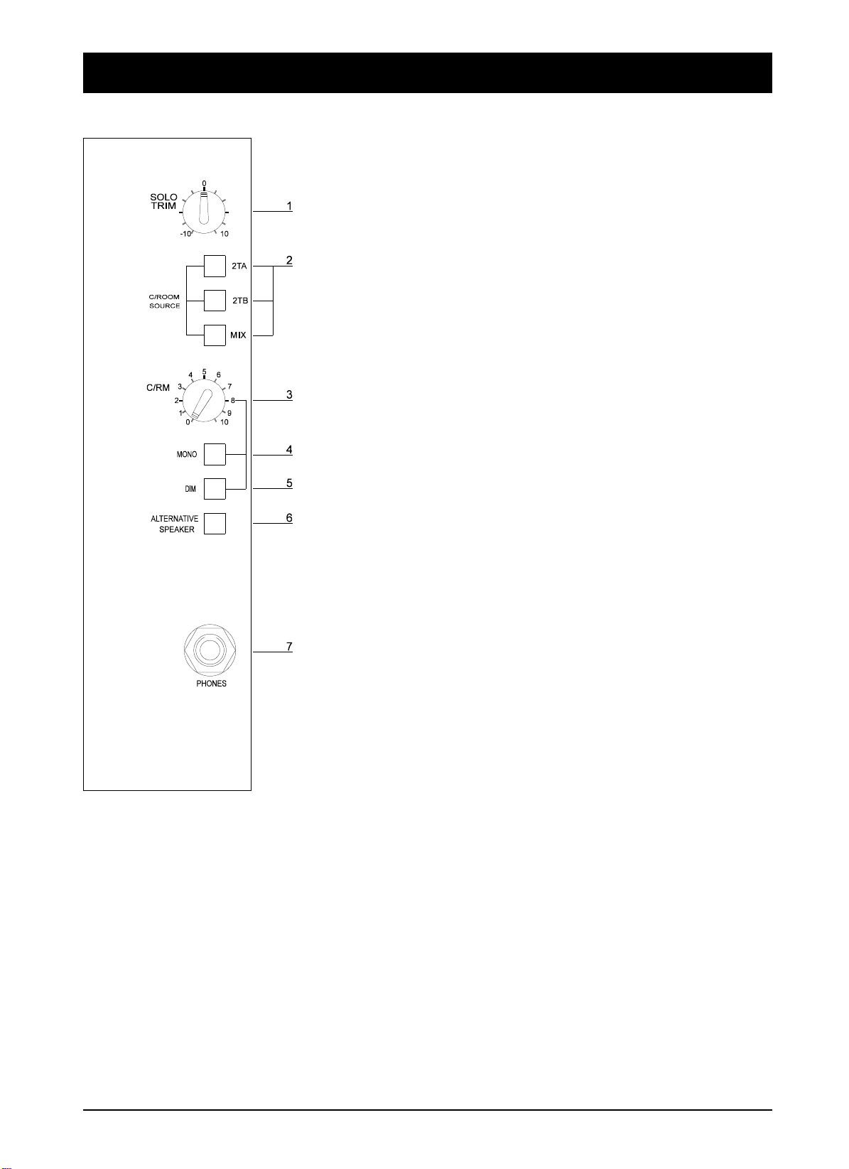
Control-room Phones and Speakers
The stereo Control-room signals are sourced from either one of two 2-track inputs
from Jacks on the rear connector panel, or from the main mix. The sources can be
mixed by pressing more than one source switc h.
In addition the Control-room signals can be sourced from the Solo/PFL/AFL
system. This allows the Control-room to listen to single, selected inpu ts rather than
the Mix.
The SOLO TRIM control sets the signal level for the Solo/PFL/AFL signals.
1
It provides a cut and boost of +/-10dB.
Control-room Source
The Control-room source selection is controlled by the 2TA, 2TB and MIX
2
switches.
The signal level available at the Phones/Speaker outputs is controlled by the
3
C/RM pot.
The two paths of the stereo signal, left & right, may be connected together by
4
pressing the MONO switch.
The output signals are attenuated by 20dB (nominal) when the latching DIM
5
switch is depressed.
The Control-room output can be switched to feed the ALTERNATIVE
6
SPEAKER outputs.
Both speaker outputs are disconnected by plugging a headphone Jack into the
7
PHONES socket.
4.36 DC2020 Control-room Phones and Speakers
Page 77

Input Rear Connector Panel
(Non-Patchbay Only)
2-Track A Left and Right Inputs - 3-pole Jacks
2-Track B Left and Right Inputs - 3-pole Jacks
Output Rear Connector Panel
(Non-Patchbay Only)
The Control-room outputs are ground compensated. This provide s a very effective
way of optimising noise immunity, without the complexity of balanced outputs.
Ground compensated outputs cancel the effects of variation in ground potential
between the mixer and other equipment which would otherwise show up as hum.
If the output is driving an amplifier that has an unbalanced input, connect the -ive
(cold) signal to the ground at the destination, not at the output of the console.
Control-room Left and Right Outputs - 3-pole Jacks
Tip Hot (in pha se signa l)
Ring Cold (out of phase signal)
Sleeve Ground
Tip Hot (in pha se signa l)
Ring Cold (out of phase signal)
Sleeve Ground
Tip Hot (in pha se signa l)
Ring Cold (ground sense)
Sleeve Ground
Alternate Left and Right Outputs - 3-pole Jacks
Tip Hot (in pha se signa l)
Ring Cold (ground sense)
Sleeve Ground
DC2020 Control-room Phones and Speakers 4.37
Page 78

4.38 DC2020 Control-room Phones and Speakers
Page 79

Patchbay
DC2020 Patchbay 4.39
Page 80

Patchbay Fascia
pbface.e ps
4.40 DC2020 Patchbay
Page 81

Patchbay Wiring
The DC2020 Patchbay is an 8-module wide panel which provides patching for up
to 40 inputs, master functions and a maximum of 120 tie lines.
The following simplified diagrams show how the Bantam-type sockets are wired.
The complete list of EDAC plug connections is given in Chapter 2.
The diagram on the right shows the
convention used in drawing the
sockets.
Line Inputs 1-24
Input Channel 1-24
Line Inputs
EDAC
(Makes contact with inserted plug)
n
Line Input n
Normalling
Line-normalling
Patchcard,
located just above
the tie lines
INS SND
n
Bantam-Type Socket
Non-break Contact
(Disconnects when plug is inserted)
LINE IN
n
INS RET
n
Break Contact
To Line
on console
Input n
From Channel
Output n
To Monitor
Input n
From Insert
Send Amp.
To Insert
Return Amp.
CH OUT
n
TP RET
n
TP SND
n
MON IN
n
Tape Send
EDAC N
DC2020 Patchbay 4.41
Page 82

Line Inputs 25-40
Input Channel 25-40
LINE IN
n
n
Note: Line Inputs 25 to 40
appear on their associated
input patchcard only, they
do not have a
normalling patchcard.
To Line
Input n
From Insert
Send Amp.
To Insert
Return Amp.
From Channel
Output n
INS SND
n
CH OUT
TP RET
n
INS RET
n
n
MON IN
TP SND
n
n
To Monitor
Input n
4.42 DC2020 Patchbay
Page 83

Group Inserts
Group Inserts
n
Group Outputs
From Group
Output n
From Group
Send Amp.
To Group
Return Amp.
Group Outputs
GROUP OUTPUT
n
SND
RET
SMPTE Timecode
SMPTE Timecode
SMPTE OUT
on back of
console
From SMPTE
Sender
SMPTE IN
on back of
console
To SMPTE
Reader
DC2020 Patchbay 4.43
SMPTE OUT
on patchbay
SMPTE IN
on patchbay
Page 84

Stereo Inputs
STE IN
on EDAC
Aux Outputs
STEREO INPUTS
Aux Outputs
AUX OUTPUT
n
n
L or R
To Stereo Input
on Console
AUX OUTPUT
ON EDAC
Aux Output
From Console.
Foldback Outputs
Foldback Output
From Console.
Foldback Outputs
FOLDBACK O/Ps
n
F/B OUTPUT
ON EDAC
4.44 DC2020 Patchbay
Page 85

Studio Phones
Studio Phones Output
From Console.
Studio Speakers
Studio Phones Outputs
STUDIO PHONES
L or R
STUDIO PHONES OUTPUT
Studio Speakers Outputs
STUDIO SPEAKERS
L or R
STUDIO SPEAKERS OUTPUT
ON EDAC
ON EDAC
Studio Speakers Output
From Console.
Mix Inserts & 2-Track Sends
Mix Outputs and 2-Track Sends
MIX OUTPUT
L or R
From Mix Output
L or R
2-TRK A
L or R
Mix and 2-Trk
Outputs
on EDAC
2-TRK B
L or R
DC2020 Patchbay 4.45
Page 86

2-Track Returns
2-Track Returns
2-TRK A or B
L or R
2-TRK Inputs
on EDAC
To 2-Trk Input
in Console
Control-room & Alternative Speaker Outputs
Control-Room and Alternative Speaker Outputs
C/ROOM OUTPUT
C/room Output
From Console.
Alternative Speaker
Output From Console.
L or R
ALT OUTPUT
L or R
CRM OUTPUT
ON EDAC
ALT OUTPUT
ON EDAC
Parallel Sockets
Tie Lines
Parallel
Parallel
Tie Lines
Tie Line n
Tie Line Input n
on EDAC N
4.46 DC2020 Patchbay
Page 87

Automation Guide
DC2020 Automation Guide 4.47
Page 88

4.48 DC2020 Automation Guide
Page 89

Introduction
DC2020 Introduction 4.49
Page 90

Introduction to the Automation
Control Panel
The Central Control Panel is the user interface for the Automation System.
The Automation Control Panel appears as follows:
Screen
The Screen is a touch-se nsitive LCD unit. There are 60 touc h-sensitive areas on the
display: 10 columns by 6 rows. The display itself consists of 76800 individual pixe ls,
arranged as 320 columns by 240 rows.
To the right of the Screen there is a small thumbwheel. This adjusts the contra s t of
the screen for optimum viewing characteristics.
Most of the screen pages follow the format shown below. There are a number of
areas on the screen: The Screen Title area, the Subsidia ry Data area, the Cursor Line
(which is touch-sensitive on most pages), the Scroll Bar with its touch -sensitive Up
and Down areas, and the Touch-pads.
4.50 DC2020 Introduction
Page 91

Keyboard
There are 22 buttons, some with illumination, which are for the functions most
commonly used during mixing; there is also a Jog Wheel which is use d for selecting
pages and timecodes. The Jog Wheel ma y also be used to control the Ta pe Machine,
providing that the Tape Machine will support this functio n.
The 22 buttons are in several groups, according to functionality. They are described
below.
Tape Machine Manual Control
Manual control of the tape machine is achieved with the five momentary buttons
which are located on the lower part of the Central Control Panel. These buttons,
which are illuminated, are:
REW, FF, PLAY, STOP and RECORD. The Tape Machine must, of course, be
suitable for remote control.
In addition to the manual command switche s there are further commands for moving
the tape. These are:
LOC0: Pressing LOC0 will cause the tape to re/wind to the position stored in
LOCATE0. LOCATE0 is stored as a time-code value.
LOC1 is similar to LOC0.
AUTOPLAY is selected by pressing the AUTOPLAY button, a LED above the
button glows to indicate selection. It is deselected by pressing the AUTOPLAY
button again. If AUTOPLAY is selected and a locate key (LOCATE 0, LOCATE1,
DROP IN or DROP OUT) is pressed, then the tape will re/wind to the Cue point
and start playing. If AUTOPLAY is not selected then the tape will stop at the Cue
point.
Note: AUTOPLAY only operates when a locate button has been used. If a cue point
is selected via the touch-screen, the tape will mo ve to the selected loca tion and stop.
AUTORETURN is selected in a similar way to AUTOPLAY.
If AUTORETURN is selected and the tape rolls past the LOCATE1 position the
tape will rewind to LOCATE0 (unless Record Enable or Preview is selected). If
AUTOPLAY is selected the tape will start playing again from LOCATE0. If
LOCATE0 is after LOCATE1 then AUTORETURN cannot be selected.
The STORE button is used to enter the tape positions which are stored in LOCATE0
and LOCATE1. The position to be stored is selected from a list of cue points on the
page. Holding down STORE and pressing LOC0 or LOC1 will store the selected
Cue point on the LCD in the appropriate locate point.
Track Record Enable
The DROP IN and DROP OUT buttons are used to set the drop-in and drop-out
points for recording onto the tape machine. They are set up in a similar way to
LOCATE0 and LOCATE1, i.e. any cue point in the cue list may be selected.
The DROP IN and DROP OUT buttons are also ’locate keys’: when they are pressed
the tape machine will re/wind to them, and start playing if AUTOPL AY is selected.
If Record Enable or Preview are selected, and Auto Return is selected, then when
the tape plays through the Drop out point, the tape will rewind to the Drop In point.
It will play if again if Auto Play is selected.
DC2020 Introduction 4.51
Page 92

Note: pre-roll and post-roll times may be set up for the Locate points and the Drop
In and Drop Out points.
RECORD ENABLE is selected by pressing the RECORD ENABLE button: a LED
above the switch glows to indicate selection. It is deselected by pressing the
RECORD ENABLE button again.
The Drop In and Drop Out points become active when RECORD ENABLE is
selected, i.e. the enabled tracks on the tape machine will drop into record when the
tape plays through, or starts from, the Drop In point. Similarly, the tracks will drop
out of record when the tape plays through the Drop Out point.
Note: the Sync. head on the tape machine should be selected when RECORD
ENABLE is selected. This is done automatically on supported tape ma chin es .
PREVIEW is selected by pressing the PREVIEW button, a LED above the switch
glows to indicate selection. It is desele cted by pressing the PREVIEW button again.
The tape machine will not drop into record at the Drop In point whe n PREVIEW is
selected; Instead, the inputs of the channels which would have been recorded are
monitored between the RECORD IN and RECORD OUT points. This allows the
material to be previewed.
The Repro. head on the tape machine should be selected when RECORD PREVIEW
is selected. This is done automatically on supported tape machines.
When RECORD ENABLE is selected, tracks may be individually enabled by
pressing the SEL switch (located next to the fader).
Individual tracks on the tape machine may be record enabled by using the
appropriate switches on the tape machine, or in the case of suppo rted ma chines, by
using the Record Enable page which may be displayed on the Automation Display.
Jog Wheel
The Jog Wheel has a variety of functions, as follows:
Associated with the Jog Wheel is the SEARCH button. Wh en the SEARCH button
is selected it causes the Jog Wheel to become a shuttle control, jogging the tape
backwards and forwards relative to a timecode reading. This is o nly ava ilable with
supported tape machines. When SEARCH is not selected, the Jog Whee l is used for
scrolling the LCD, and for setting numerical values on the LCD.
The Jog Wheel also has an integral switch which is activated by pressing down on
the Jog Wheel. It is used in the alphanumeric and timecode editing screens .
Mix Automation
Automated Mixing is selected by pressing the MIX ON button, a LED beside the
switch glows to indicate selection. It is deselected by pressing the MIX ON button
again.
The ABORT button is used if you decide that you do not want to save a new mix.
The adjacent LED glows when ABORT is active.
The TRANSFER button is used to create a cue in the cue list. The timecode
associated with the cue is the timecode at the instant the TRANSFER button is
pressed.
The SETUP button takes you straight into the Set-up Screen.
4.52 DC2020 Introduction
Page 93

The GLIDEBACK button swi tches GLIDEBACK mode on and off: an ad jacent
LED indicates its status.
Glideback determines how motorised faders react when they are in Armed mode,
and when they change from Write to Read Mode.
The MODE SNAP button may be used at any time to store a snapshot of the modes
of all of the Automated functions. Only one such snapshot may be stored at any
time.
To store a snapshot you press and hold the STORE button and then press the MODE
SNAP button.
To recall the snapshot you press the MODE SNAP button.
The GROUP ASSIGN button takes you to the GROUP ASSIGN page. When the
Group Assign page is active, input channels may be a ssigned to the Control Groups
by using the SEL switches on the channels.
Disk Drives
A 3.5 inch 1.44Mbyte floppy disk drive is mounted underneath the armrest. It is
used as the removable storage medium for the sys tem. The disks use the same format
as an IBM-compatible PC.
A Hard Disk Drive is fitted internally.
DC2020 Introduction 4.53
Page 94

4.54 DC2020 Introduction
Page 95

Project Management
DC2020 Project Management 4.55
Page 96
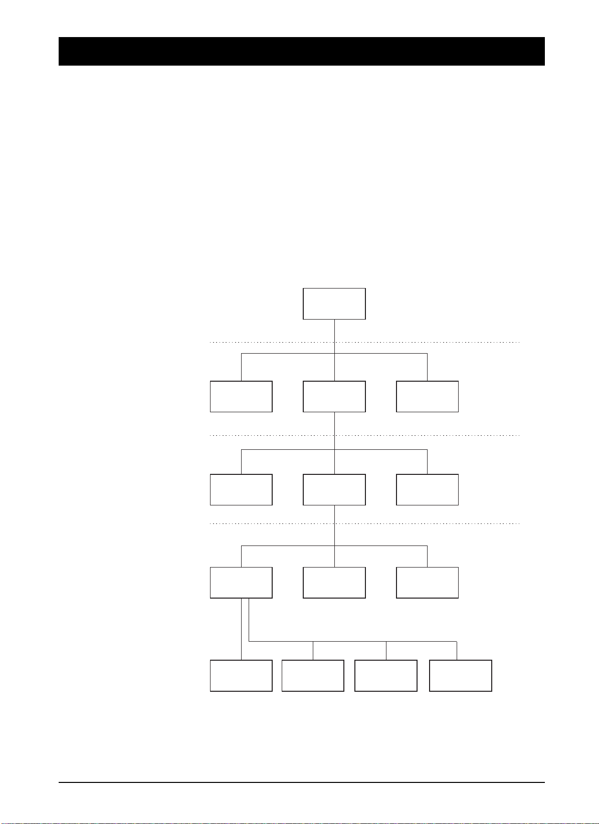
Introduction
The DC2020 features a project management system, designed to provide easy
storage and retrieval of mix data. The system mean s that the console can be u sed by
a large number of different engineers, each working on their own projects, and
enables each engineer to store mixes for his/her various projects in a directory
system, where they can be easily located and recalled in the future. In addition, other
information and text relating to each mix can be stored in the same location, and
can also be recalled later.
The directory system is accessed and displayed via the touch screen, but as each
screen page only shows one level of the system at a time, it is not easy at first to
visualise the structure by looking at the touch scre en. The following diagram shows
the structure of the directory system.
The Directory Structure
Tape Machine,
Studio
Date,
Time
Studio Page
User Page
Project Page
Mix Page
User 1 User 2 User 3
Project 1 Project 2 Project 3
Title 1 Title 2 Title 3
Mix Pass 1Cue List Mix Pass 2 Mix Pass 3
Fader Recall,
Backup Depth,
Password
Memos,
Elapsed Time
Timecode,
Frame Rate,
Pre & Post-roll,
Console Remapping,
Channel & Track Lists,
Mix Lists
+ Setup System
(via SETUP button)
4.56 DC2020 Project Management
Page 97

As shown, the system is a tree structure starting from the root directory, ’Studio’.
Below this are a number of ’Users’, below each User a number of ’Projects’, below
each project a number of ’Titles’, and finally within each Title, a ’Cue List’ and a
number of ’Mix Passes’.
It is possible to create any number of Us ers , Pro jects, T itles a nd Mix Pas ses with in
each level, the only limit is the amount of Hard Disk storage available for mix data.
Note that the mix data itself from each Mix Pass is only actually stored at the bottom
of the directory system, within each Title file. No mix data is stored at any other
level, so even if you create 50 User directories, yo u will not have used up any Hard
Disk Space until you start to save mixes in one of those directories.
On power-up, the console defaults to the bottom level, known as the ’Mix Page’, of
the directory which was last being used. This allows mixing to begin immediately
assuming the same user is still working on the same project. This page displays the
Cue List for the last title worked on, plus some touch-pads to allow acce ss to other
pages and functions and the rest of the directory system.
So to view the directory system having powered up the console, carry out the
following instructions:
Exit the Mix Page by pressing the ’Project’ touch-pad on the touch screen, which
moves you upwards in the directory system by one level. You are now on the Project
Page.
Press the ’User’ touch-pad on the screen, which moves you upwards one more level,
to the User Page.
Press the ’Studio’ touch-pad on the screen to take you up finally to the Studio Page,
which is the top level in the directory system.
The Studio page
This consists of a list of Users, although with a new console from the factory, there
will be only one ’default’ user, ’User 0001’.
You can create as many user directories as necessary by pressing the ’New User’
touch-pad on the screen, and name them by pressing the ’Edit User’ touch-pad. A
newly created User is given the default name ’User 000X’ until it is edited.
Once you have more than one User directory, you can select the one you want by
either turning the jog wheel on the computer surround, or touching the up or down
arrows on the right hand side of the screen. This moves the list up or down through
the cursor line (two horizontal lines in the centre of the screen).
To activate the selected user, either touch the screen in the central area, or press
down on the jog wheel. In either case, you can only select the item which is between
the two lines of the cursor line.
Selecting a User takes you down to the next level down on the Directory system,
which is the User page.
Before exiting the Studio Page, let’s have a look at the peripheral pages available
at this level. Press the ’Studio Config’ touch-pad on the screen. This brings up the
’Studio Config’ page, which allows you to set up or change the following:
"The name of the studio (set to ’Soundcraft’ at the factory)
"The type of tape machine being used (set to Midi Timecode Master a t the factory)
"The local date and time. (set to UK local time at the factory)
DC2020 Project Management 4.57
Page 98

To change any of these, simply touch the relevant part of the screen, which will
bring up either the QWERTY keyboard, list of supported machines, or numerical
keypad respectively.
Other information displayed on this page includes the percentage amount of free
hard disk space available, the software version number being run, and the number
of channels in the console.
Return to the Studio page by pressing ’OK’ on the screen.
You may also visit the Studio Utilities page. A description of these utilities is given
in the Automation Pages section of this manual.
Descending the Directory system
We can now work back down the directory system, looking in more detail at the
other facilities available at each level. Select a User, as described earlier.
The User Page
The User page displays a list of the Projects available for the currently selected User,
and as with the Studio page, with a new console from the factory there will be only
one ’default’ project, ’Project 0001’. You can create a s many Projects as nece ssary,
using the New Project touch-pad on the screen, and name them using the Edit User
touch-pad.
There is a User Configuration page and a User Utilities page which are accessible
via touch-pads.
A Project is selected in the same way as for the User, and selecting a Project takes
you down to the next level down on the Directory system, which is the Project page.
The Project page
The Project page displays a list o f all the Titles av ailable in the curren tly-selected
Project, and with a new console from the factory there will be only one ’default’
Title, ’Title0001’.
You can create as many Titles as necessary, using the New Title touch-pad on the
screen, and name them using the Edit Title touch-pad.
A Title is selected in the same way as for the previous pages, and selecting a Title
takes you down to the next level down on the Directory system, which is the Mix
page.
The Mix Page
We have now returned to the page which is always displayed immediately after
power-up. The console remembers which directory you were working in when the
power is turned off, and returns to the same place on power-up.
The Mix page has a slightly different format to the Studio, User and Proje ct pag es.
It displays the ’Cue List’ for the currently selected Title, as well as touch-pads to
access other automation functions, the most important being the list of ’Mix Passes’
associated with the Title. This is accessed by pressing the Mix List touch-pad on
the screen. (With a new console from the factory, the list will be empty and will say
’No Mixes’)
The Mix List is very useful, as it allows you to keep track of the number of Mixes
you have saved for the current Title, the size of the data file for each mix, the date
and time the mix was saved as well as allowing you to select any p revious mix a nd
4.58 DC2020 Project Management
Page 99

recall it, delete unwanted mixes or ’protect’ valuable mixes to guard against
accidental deletion. You can also name each individual mix if required, although
the system gives each mix a default number as they are created, so naming is not
essential.
The Mix list is exited by selecting the required mix using the jog wheel or
side-arrows on the screen, in the same way as for the other directory pages.
Selecting a mix returns you to the Mix page, with the newly selected mix pass loaded
and ready to play. The name of the mix (if previously entered) and its number are
displayed at the top of the screen. This will also say ’No Mixes’ if the console has
never been used before.
DC2020 Project Management 4.59
Page 100

4.60 DC2020 Project Management
 Loading...