

Page 1

V 2.0
Setup Guide
Setup Guide
Setup GuideSetup Guide
Revised: 04-12-00
Page 2

Digital 328 v2 and Frontier
Digital 328 v2 and Frontier
Digital 328 v2 and FrontierDigital 328 v2 and Frontier
Design Group Dakota Setup Guide
Design Group Dakota Setup Guide
Design Group Dakota Setup GuideDesign Group Dakota Setup Guide
Contents
1111 Connecting The System 2
2222 Digital 328 Setup 4
3333 Dakota Setup 7
4444 Using The Dakota With The 328 14
Dakota Setup Guide
1
Page 3
Connecting The System
/
Connecting The System
Connecting The SystemConnecting The System
1
Audio Connections
Audio Connections
Audio ConnectionsAudio Connections
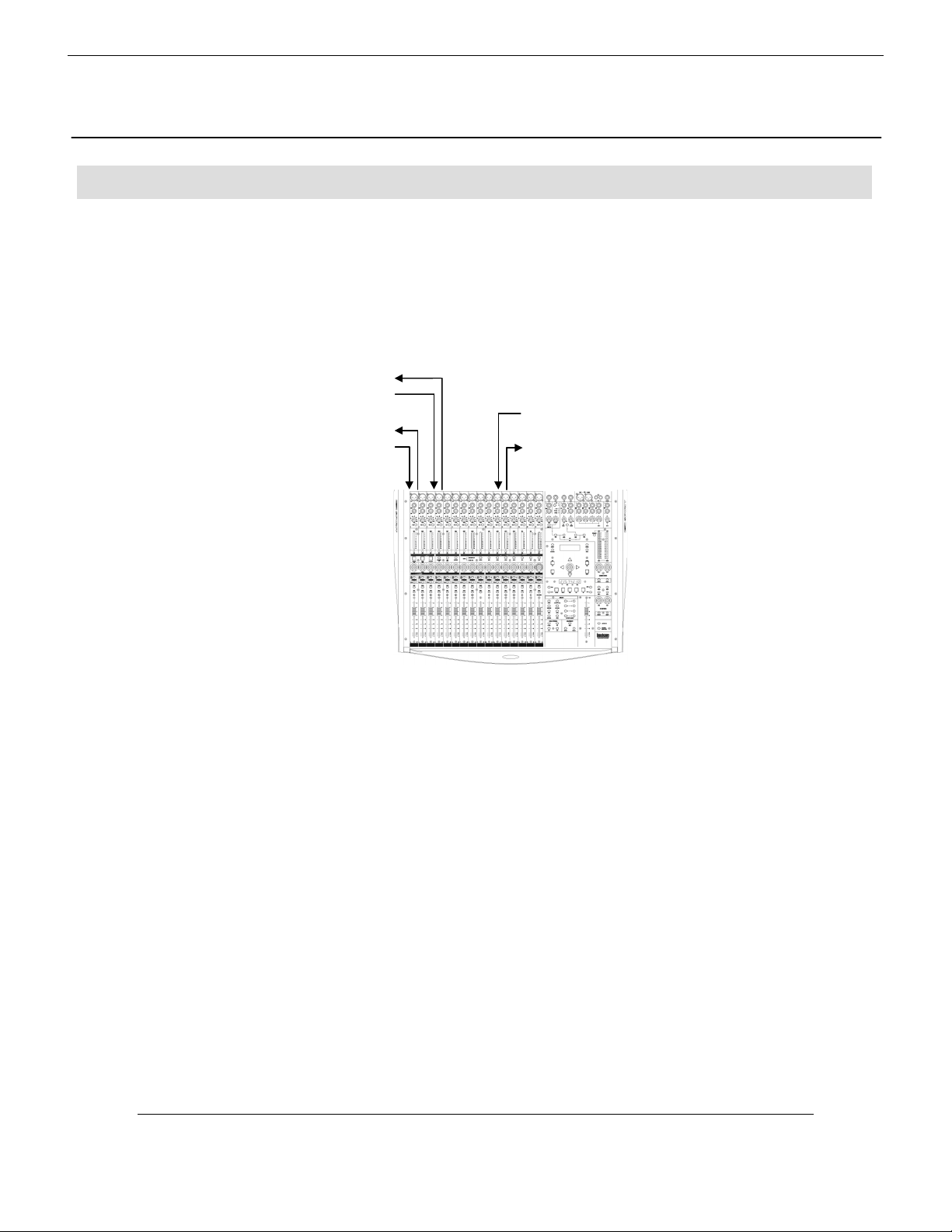
Audio connections should be made as shown in the diagram below. Toslink optical cables must
be connected both from ADAT Out port A of the Dakota card to the ADAT In port A of the 328
and vice versa, and from ADAT Out port B of the Dakota card to the ADAT In port B of the 328
and vice versa. 75Ω Coaxial digital S/PDIF cables must also be connected from the Dakota
S/PDIF output to the 328 S/PDIF input and vice versa.
328 ADAT Out B Î Dakota ADAT In B
Dakota ADAT Out B Î 328 ADAT In B
328 ADAT Out A Î Dakota ADAT In A
Dakota ADAT Out A Î 328 ADAT In A
Dakota S/PDIF Out Î 328 S/PDIF In
328 S
PDIF Out Î Dakota S/PDIF In
2
In this configuration, the ADAT connections allow digital transfer of either direct outputs from the
328’s input channels 1-8 to the Dakota card, or the 328’s 8 Group outputs. The S/PDIF output
from the console can be assigned to either the Mix output or to 1 of 3 stereo auxiliary outputs
(Aux 1/2, Aux 3/4, FX 1/2, Groups 1-8 and Control Room). The 328 S/PDIF Input can be
configured as a digital Stereo Input or as a digital 2 Track Return.
Spirit Digital 328 v2
Page 4
Other Connections
Other Connections
Other ConnectionsOther Connections
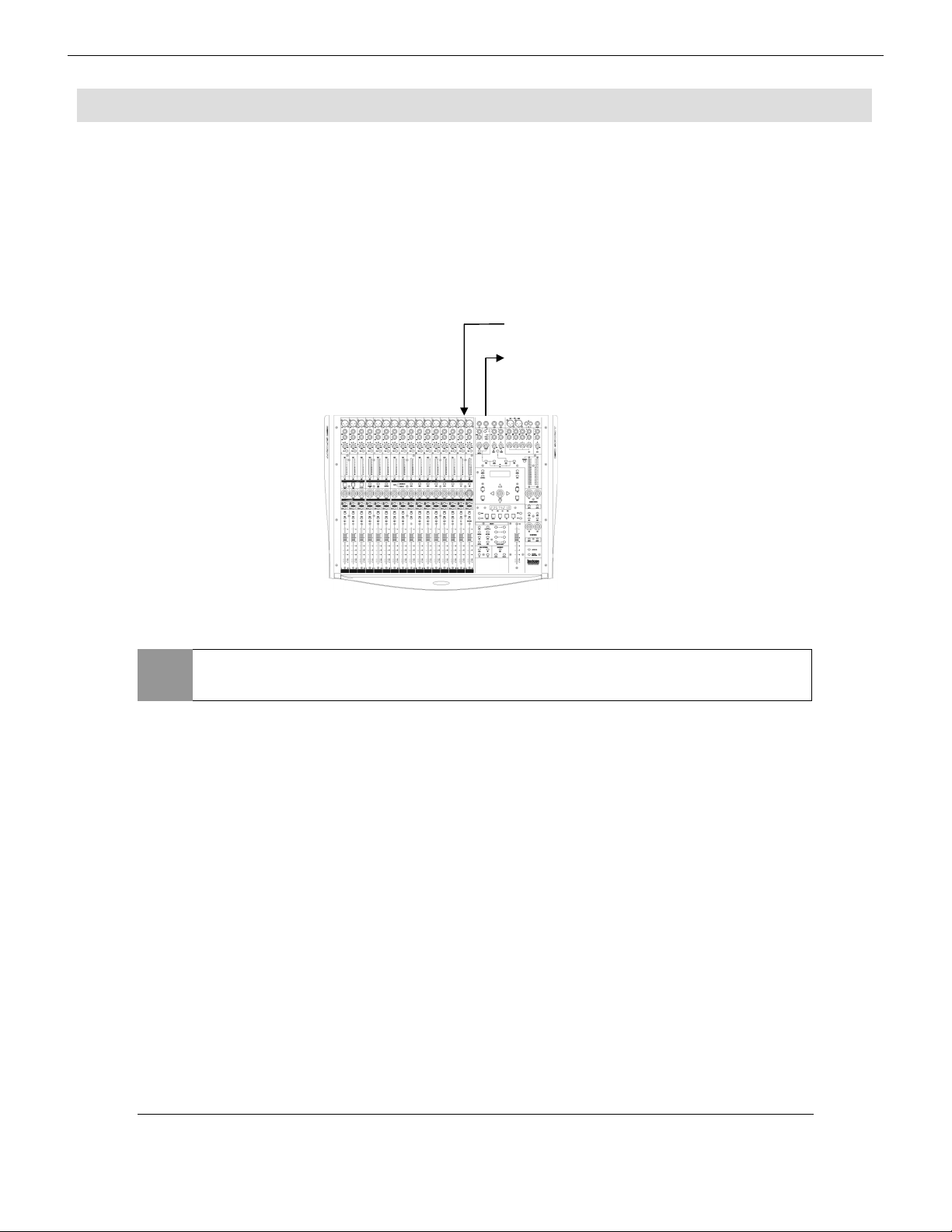
You may also wish to connect the 328 to the Dakota card via MIDI to allow MIDI
automation/System Exclusive dumps from the 328 to be recorded and played back from your PC.
If you wish to connect the 328 to the Dakota card via MIDI, the following connections must be
made:
Dakota MIDI Out 1 Î 328 MIDI In
NOTE
Either Dakota MIDI port 1 or MIDI port 2 can be used. It would be wise
to use the same number Dakota MIDI port for 328 connection.
Dakota Setup Guide
3
Page 5
<T
Ch17->24 >
2
Digital 328 Setup
Digital 328 Setup
Digital 328 SetupDigital 328 Setup
The Dakota card and the 328 (plus any other devices in the studio setup) must have their
internal clocks synchronized to allow correct transmission and reception of digital information
throughout the system. This is achieved by configuring one of the devices as a wordclock master,
and configuring all other devices in the studio setup to slave to this wordclock, hence
synchronizing all clocks in the studio setup.
In this case, the 328 will be set to wordclock master, and the Dakota will be set to slave to the
328, via the Dakota S/PDIF input. Any other devices interfacing digitally with the 328 within the
studio setup will also be configured to slave to the 328’s wordclock.
Wordclock information is automatically embedded into the S/PDIF data
NOTE
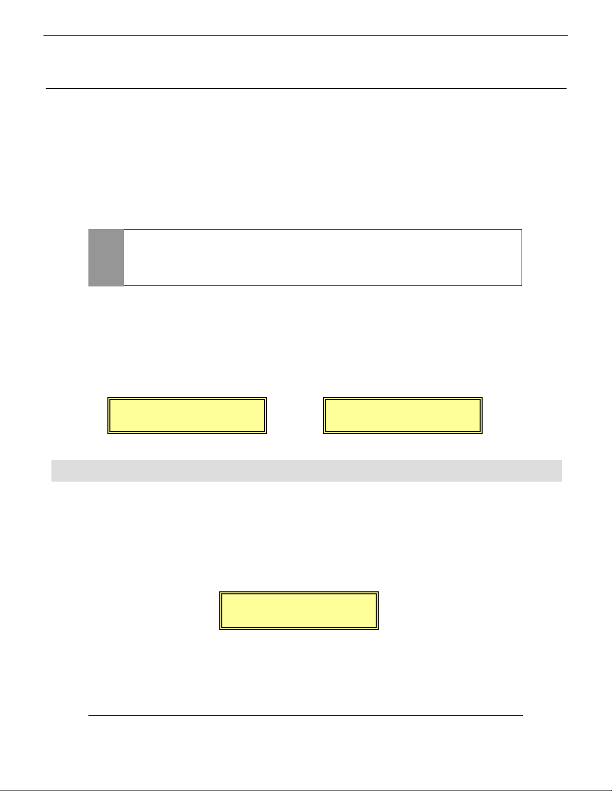
To configure the Digital 328 as the wordclock master, enter the 328’s Main Menu page by
pressing the <MENU> button to the right hand side of the LCD display. Using the rotary
encoder beneath the display, scroll up or down until the ‘Clock Source Sel’ menu is highlighted,
and press <ENTER>. Here, either ‘Internal 44.1kHz’ or ‘Internal 48kHz’ clock must be selected
for the 328 to function as wordclock master. Set this to the samplerate you wish to work at then
press <ENTER> to confirm the samplerate setting.
stream output by the 328, allowing the Dakota to slave to the 328’s
S/PDIF output, providing clock synchronization between the 328 and
the Dakota.
<Wordclock Src.>
Internal:44.1kHz
Tape Ports
Tape Ports
Tape PortsTape Ports
To ensure that the Digital 328 Tape Ports are configured to ‘ADAT’ to work with the Dakota,
enter the 328 Menu pages by pressing the <MENU> button to the right hand side of the LCD
display. Using the rotary encoder beneath the display, scroll up or down until the ‘Tape Port
Select’ menu is highlighted and press <ENTER>.
Now repeatedly press the Up cursor arrow until the ‘<Tape Ch17-24 >’ menu page is displayed.
Using the rotary encoder set the ‘Bank Source’ to ‘ADAT’:
Now press the Down cursor arrow once, to set the wordlength. The Dakota is capable of 24 bit
recording, and so for optimum results, 24 bit wordlength can be selected here. If your sequencer
supports 16 or 20 bit resolution, make this setting here – Check your sequencer manual for more
information.
or
ape
Bank Source:ADAT
<Wordclock Src.>
Internal:48.0kHz
Spirit Digital 328 v2
4
Page 6

Set the desired wordlength on the 328 with the rotary encoder.
< SPDIF
>
R
< SPDIF
>
R
< SPDIF
>
R
< SPDIF
>
R
<T
Ch17->24 >
ape
Wordlength: 24
Press the down cursor to set the port for 328 ADAT port B, as for port A, and again to set the
wordlength for port B. Press <ENTER> to confirm the settings.
<Tape Ch25->32 >
Bank Source:ADAT
S/PDIF Input
S/PDIF Input
S/PDIF InputS/PDIF Input
The 328 S/PDIF input can be routed to any one of the following inputs:
Stereo Input 1, Stereo Input 2, FX Return 1, FX Return 2, 2 Track Tape Return,
providing that the AES/EBU input or oscillator has not already been assigned to that input.
Commonly the Dakota S/PDIF output would be routed to Stereo Input 2, or the 2 Track Tape
Return input.
NOTE
Press <MENU> to enter the menu pages, scroll through the pages until the ‘SPDIF I/P Setup’ is
highlighted and press <ENTER>. Using the rotary encoder, select the destination for the
S/PDIF input, and press <ENTER> to confirm the setting:
Assigning a digital source to an input will override any analogue signal
present on that input.
<Tape Ch25->32 >
Wordlength: 24
NOTE
Input
oute To: STE-1
oute To: FX-1
Input
oute To: 2TRK
If the S/PDIF input is not required, NOWHERE should be selected in the
menu.
oute To:NOWHERE
Input
Input
Dakota Setup Guide
5
Page 7

S/PDIF Output
< SPDIF Output >
< SPDIF Output >
< SPDIF Output >
< SPDIF Output >
S/PDIF Output
S/PDIF OutputS/PDIF Output
On the 328, the stereo S/PDIF output can be sourced from any of the following busses:
Mix L/R, Aux 1/2, Aux 3/4, FX1/2
This will usually be set to ‘Mix’, to allow a stereo mixdown to be recorded directly into the Dakota
on the playback of a composition.
As the Dakota is a full duplex device, it is possible to playback a composition consisting of all 8
ADAT tracks + 1 Stereo S/PDIF track from the Dakota, recording the mixed signal from the 328
back into the Dakota S/PDIF input as a stereo mixdown.
Press <MENU> to enter the menu pages, scroll through the pages until the ‘SPDIF O/P Setup’ is
highlighted and press <ENTER>. Using the rotary encoder, select the source for the S/PDIF
output
Src From: MIX
Src From: FX1/2
Src From: AUX1/2
Src From: GRP1/2
< SPDIF Output >
Src From: CRM
If the S/PDIF output is not required, NOWHERE should be selected in
NOTE
The wordlength of the S/PDIF output must now be set. Press the down cursor to access the
S/PDIF output wordlength setting. Here, the desired wordlength can be set to 16, 20 or 24 bit.
the menu. In this case, wordclock will still be transmitted through the
S/PDIF output of the 328, even though no audio signal is being
transmitted.
NOTE
6
If using the Dakota as an ASIO device, it is important here that the
wordlength set here is the same as the 328 Tape Port wordlength (See
‘Tape Port’ section earlier in this chapter).
Spirit Digital 328 v2
Page 8

Wordclock & S/PDIF Input
Wordclock & S/PDIF Input
Wordclock & S/PDIF InputWordclock & S/PDIF Input
The Dakota must be set up to receive the wordclock transmitted by the 328 (via the 328’s S/PDIF
output).
Open the Dakota Control Panel, accessed by double clicking the Dakota icon on the Windows
Taskbar:
Click on the ‘Clock/Device Status’ tab. The following window should open:
Dakota Setup
Dakota Setup
Dakota SetupDakota Setup
3
Dakota Setup Guide
7
Page 9

Firstly, the Dakota clock source must be set to slave its internal clock to the incoming S/PDIF
wordclock (outputted from the 328). Set ‘Clock Source’ to Dig In: ‘S/PDIF’:
NOTE
Now the samplerate must be set. In the ‘Sample Rate’ section, select the samplerate you wish to
work at. This should match the samplerate of the internal clock on the 328, which was configured
in section 2 of this Setup Guide:
Alternatively, the Dakota will also successfully clock to either ADAT
output of the 328. The Dakota could also be set as wordclock master,
and the 328 can slave to the Dakota via the S/PDIF connection.
However, the recommended configuration is with the 328 as wordclock
master, with the Dakota slaving via S/PDIF, as outlined in this Setup
Guide.
8
Spirit Digital 328 v2
Page 10

NOTE
On the Dakota, the stereo device ‘S 1:2’ (S/PDIF format) can be sourced from any physical input.
In this configuration, it must be set to source from the Dakota coaxial S/PDIF input. With the
‘S 1:2’ input set to ‘Coax’, the Dakota receives the S/PDIF stream from the 328, enabling the
Dakota to slave to the 328 via S/PDIF, and also allows the 328 to send S/PDIF stereo data back
to the Dakota.
To make this setting, select ‘Coax’ from the ‘S 1:2’ pull-down menu.
You can force Windows applications to only playback at the chosen
samplerate by ticking the ‘Lock’ tick box in the ‘Sample Rate’ section.
Dakota Setup Guide
9
Page 11

Now the validity of the S/PDIF input received by the Dakota must be checked. The ‘Digital Input
Status’ section of the ‘Clock/Device Status’ Dakota Control Panel shows the validity of the S/PDIF
input with the following 3 indicators:
S/PDIF input status indicators (From left to
right): Signal Active/Inactive, Digital Audio
Format Valid/Invalid, Dakota Locked/Unlocked
Firstly, click on ‘Clear Errors’ to initialize the indicators.
In this configuration, all indicators should be continuously showing green. If any of the indicators
are red, or display a slash, the S/PDIF being outputted by the 328 is not correctly being
interpreted by the Dakota. If this is the case, check the S/PDIF cable is correctly connected from
the S/PDIF output of the 328 to the S/PDIF input of the Dakota. If the indicators are still showing
errors, check also that all the correct 328 and Dakota settings have been made, as described so
far in this Setup Guide.
A 75ΩΩΩΩ coaxial S/PDIF cable must be used to correctly transfer the
NOTE
If all three indicators are continuously showing green, the Dakota is correctly slaving to the 328’s
wordclock, and the S/PDIF data format is being correctly interpreted by the Dakota.
S/PDIF digital data from the 328 to the Dakota. A standard phono cable
will not guarantee satisfactory data transfer.
10
Spirit Digital 328 v2
Page 12

S/PDIF Output
S/PDIF Output
S/PDIF OutputS/PDIF Output
The stereo output from the Dakota can be set to either AES/EBU or S/PDIF format. In this
configuration, this should be set to S/PDIF, so that the 328 correctly interprets the stereo data
incoming to the 328’s S/PDIF input.
In the Dakota Control Panel, select the ‘System’ tab. In the ‘Output Channel Status’ section,
select ‘Consumer (S/PDIF)’:
Dakota Setup Guide
11
Page 13

ASIO Resolution
ASIO Resolution
ASIO ResolutionASIO Resolution
If you wish to use the Dakota as an ASIO device (e.g. with Cubase VST), the playback/record
wordlength should also be set. The Dakota supports both 16 bit and 24 bit ASIO wordlength
resolution. Set the desired wordlength resolution in the ‘System’ page of the Dakota Control
Panel under the ‘ASIO Resolution’ section:
12
NOTE
If you are using the Dakota as an ASIO device it is important that the
wordlength set here is the same as the 328 S/PDIF output wordlength
and also the same as the 328 Tape Port wordlength. The PC software
supporting the ASIO devices (e.g. Cubase VST) must also be set to work
at this resolution – see the software manual for more information. This
maintains an optimum bit resolution throughout the entire system. See
Section 2 - ‘Digital 328 Setup’ for information on making these settings
on the 328.
Spirit Digital 328 v2
Page 14

MIDI
MIDI
MIDIMIDI
If you wish to use the MIDI interface on the Dakota with the 328, ensure that the MIDI mode is
enabled on the Dakota Control Panel. With the System page still open, in the ‘MIDI Mode’
section, select ‘2x2’:
MIDI information can now be recorded and played back via the Dakota. Connecting the 328 to
the PC via the Dakota MIDI interface has several benefits:
• MIDI automation data from the 328 can be recorded into a sequencer, which can then be
replayed at any time to allow full dynamic automation of the 328.
• MIDI (System Exclusive) data dumps from the 328 to be saved onto the PC, which can be
restored into the 328 at any time. This enables the PC to be used as a MIDI librarian where
all the data stored in the 328 (snapshots, presets etc.) can be backed up to a small system
exclusive file on the PC.
328 software v1.1 and above users only:
•
bank) can be used to remotely automate Windows software, e.g. Propellerhead’s Rebirth
338, Native Instrument’s Reaktor, Bitheadz Retro-AS1, vritual mixing consoles – practically
anything that responds to MIDI controller changes!
The MIDI Controller bank on the 328 (‘hidden’ fader
Dakota Setup Guide
13
Page 15

Using The Dakota With The 328
Using The Dakota With The 328
4
Using The Dakota With The 328Using The Dakota With The 328
Accessing The Dakota ADAT I/O From The 328
Accessing The Dakota ADAT I/O From The 328
Accessing The Dakota ADAT I/O From The 328Accessing The Dakota ADAT I/O From The 328
The Dakota will commonly be used with a software sequencer/hard disk recorder to allow the
simultaneous playback and recording of 8 individual tracks of audio, via the ADAT I/O. Here, the
software application must be configured to access the Dakota ADAT I/O via the relevant
Windows device drivers that came with the Dakota.
When playing back audio tracks from the software application, tracks 1-16 will be accessible from
channels 17-32 respectively in the Tape Fader Bank on the 328.
To record a signal onto a track within the software application, send the required channels to
Tape Sends 1-16. See the 328 manual for full instructions on how to send a channel to tape.
NOTE
Accessing The Dakota S/PDIF I/O From The 328
Accessing The Dakota S/PDIF I/O From The 328
Accessing The Dakota S/PDIF I/O From The 328Accessing The Dakota S/PDIF I/O From The 328
You may wish to utilize the Dakota S/PDIF output to transmit a stereo signal to the 328. Again
the software application must be configured to access the Dakota ‘S 1:2’ S/PDIF output via the
relevant Windows device drivers that came with the Dakota.
The stereo Dakota S/PDIF input will be accessible on the 328 from either
depending on the 328 S/PDIF input setting (see the ‘S/PDIF input’ section in chapter 2 of this
guide).
The 328 can also be configured to transmit a stereo signal back to the Dakota via the Dakota
S/PDIF input. Here the 328 can be set to either transmit any of the following signals to the
Dakota S/PDIF input:
Ensure that the relevant device drivers are fully installed for the
software application to correctly access the Dakota ADAT I/O.
Stereo Input 1, Stereo Input 2, FX Return 1, FX Return 2, 2 Track Tape Return,
Aux 1/2 sends, Aux 3/4 sends, FX 1/2 sends, Groups 1-8 and Control Room
14
The desired setting can be configured via the ‘S/PDIF O/P Setup’ menu on the 328 (see the 328
manual for full instructions).
Again, ensure that the relevant drivers are fully installed for the software application to correctly
access the Dakota S/PDIF I/O.
Spirit Digital 328 v2
Page 16

Spirit by Soundcraft
Harman International Industries Ltd., Cranborne House,
Cranborne Road, Potters Bar, Herts EN6 3JN, England.
Tel: +44 (0)1707 665000 Fax: +44 (0)1707 665461
http://www.spiritbysoundcraft.com
e-mail: spiritsupport@soundcraft.com
Dakota Setup Guide
15
 Loading...