

Page 1
Quick Start Guide
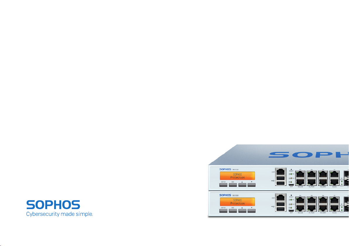
SG 310/330 Rev. 2
Page 2

Before you begin please confirm that you have a
working Internet connection and make sure you
have the account information available that was
provided by your ISP.
1. Before Deploying
Congratulations on your purchase of the Sophos SG appliance to protect your data
networks and computers. This Quick Start Guide describes in short steps how
to assemble the appliance and explains how to open the web-based WebAdmin
configuration tool on the security system from your administration client PC.
WebAdmin allows you to configure every aspect of the security system.
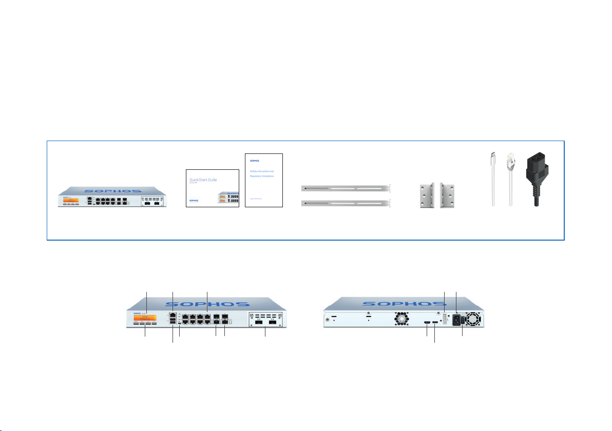
a) What does the box include
SG 310/330
(1U rack mount chassis)
SG 310/330 Rev. 2
Multi-function
LCD display
Navigation
for LCD
1 x COM
(RJ45)
2 x
USB 3.0
Quick Start Guide SG 310/330 Rev. 2
This Quick Start Guide and
Security Notes
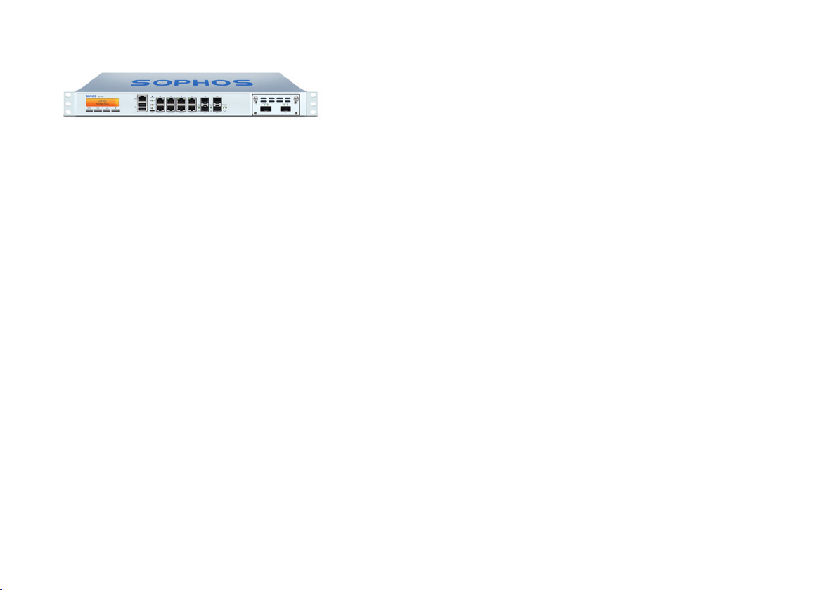
b) Device Images*: Front and Back
8 x GbE copper – fixed. Incl. 2
bypass pairs (ports E0/1 and E2/3)
Micro USB
SFP
ports
2 x
1 further expansion
2 x
SFP+
with optional FleXi
ports
bays (shown here
Port module)
2 rack mount rails
Connector for redundant
external power supply
* The displayed images are of SG 330 device. The SG 310 device may vary slightly.
2 rack
mount brackets
1 x HDMI
1 x
USB 3.0
Power
supply
Power switch
RJ45 Ethernet cable
1 power cable
Micro USB cable
1
Page 3
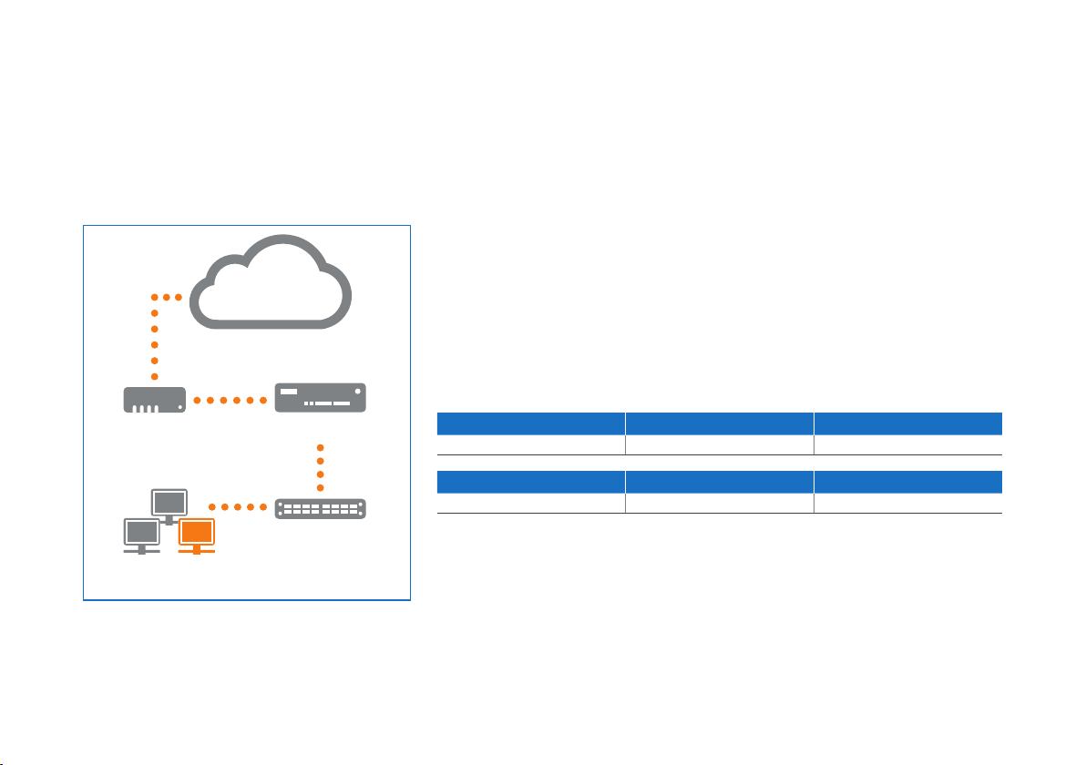
E1/any port
e.g.,
DSL modem
Internal network
admin client PC
Internet
UTM Appliance
Switch
E0/
LAN
License
The security appliances are delivered with a 30-day trial version. During or after
the trial period, you can activate the full license you purchased from your Sophos
partner by creating an account at https://myutm.sophos.com, activating the provided
activation and upgrade keys, and uploading the created license file into your appliance.
2. Mount and connect the device
Connect the ports to the internal and external networks
1. Connect the E0/LAN port via a hub or switch to the internal network. For this
purpose, please use the RJ45 Ethernet cable of the scope of supply. Note that your
administration client PC must also be connected to this network.
2. Connect the E1/WAN port to the external network. The connection to the WAN
depends on the type of Internet access.
The UTM appliances are shipped with the following default settings:
Ethernet Port IP Address Zone
E0/LAN 192.168.0.1/255.255.255.0 LAN
Default Gateway DNS Proxy DHCP Service
None Enabled Disabled
Quick Start Guide SG 310/330 Rev. 2
2
Page 4
Workstation connection properties:
IP address: Any address in the range 192.168.0.2
through 192.168.0.254
Netmask: Enter 255.255.255.0
Standard gateway: Enter the IP address of
the appliance’s internal network card E0/LAN:
192.168.0.1
DNS server: Enable this option and enter the IP
address of the internal network card E0/LAN:
192.168.0.1
Mount the appliance to the rack
Please follow the rack mounting instructions as described in the UTM Operating
Instructions.
*
3. Power Up the Device
Connect the power cable and turn on the device
Connect the device to the power supply using the power cable(s). Turn the device
on. The power switch is on the back of the device and is placed next to the power
connection. Once the device has booted completely, you’ll hear an acoustic signal:
five beeps in a row.
4. Configure the device
Use your browser to make the initial connection to the WebAdmin GUI
You will need to configure a workstation with the necessary LAN properties to access
WebAdmin. You can change these settings later to match your existing network. The
location of the menu for these settings depends on the operating system of your client.
Example: With Windows 7, the menu can be found under Start >> Control Panel >>
Network and Sharing Center
Start the browser and enter the management IP address of the appliance:
https://192.168.0.1:4444
Accept the security notice by clicking OK (Mozilla Firefox) or Yes (MS Internet Explorer).
For configuration you can follow the initial setup wizard described in the WebAdmin
Quick Start Guide** or cancel it and perform a manual setup (see the UTM
Administration Guide*).
Quick Start Guide SG 310/330 Rev. 2
* Available at www.sophos.com/en-us/support/documentation/sophos-utm
** Available via WebAdmin >> Support >> Manual
3
Page 5
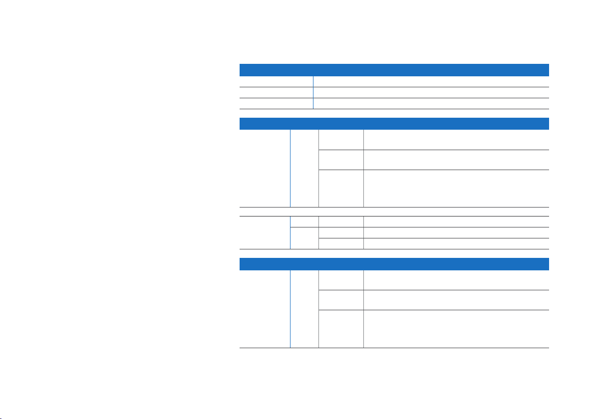
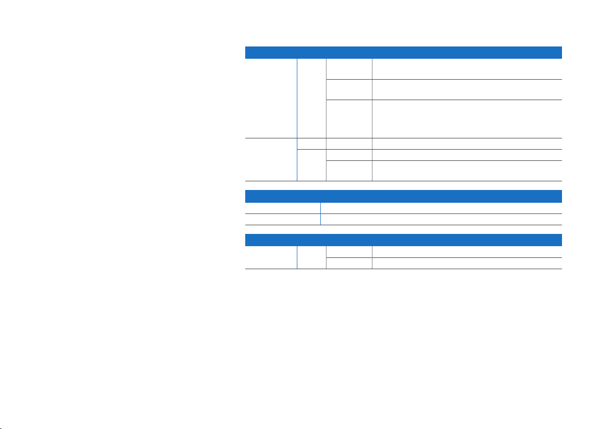
5. Device LED Status
Power (LED Display)
Power Supply Acitve Green
Power Supply Failure Red
SSD Active Blue
LEDs on each RJ45 Ethernet connector
ACT/LNK
(Left LED)
Green Constantly 1. The Ethernet port is receiving power.
Flashing The adapter is sending or receiving network data. The
Off 1. The adapter and switch are not receiving power.
2. Good connection between the Ethernet port and hub.
frequency of the flashes varies with the amount of traffic.
2. No connection between both ends of network.
3. Network drivers have not been loaded
or do not function correctly.
Quick Start Guide SG 310/330 Rev. 2
Speed
(Right LED)
LEDs on each SFP connector
ACT/LNK Green Constantly 1. The SFP connector is receiving power.
Amber On The Ethernet port is operating at 1,000 Mbps.
Green On The Ethernet port is operating at 100 Mbps.
Off The Ethernet port is operating at 10 Mbps.
2. Good linkage between the SFP connector and hub.
Flashing The adapter is sending or receiving network data. The
frequency of the flashes varies with the amount of traffic.
Off 1. The adapter and switch are not receiving power.
2. No connection between both ends of network.
3. Network drivers have not been loaded
or do not function correctly.
4
Page 6
LEDs on each SFP+ connector
ACT/LINK
(Left LED)
ACT/LINK
(Right LED)
LAN Bypass (LED Display)
LAN Bypass Active Green
LAN Bypass Off Off
Back side
Power Supply Green Constantly Power
Green Constantly 1. The SFP+ connector is receiving power.
2. Good linkage between the SFP+ connector and hub.
Flashing The adapter is sending or receiving network data. The
frequency of the flashes varies with the amount of traffic.
Off 1. The adapter and switch are not receiving power.
2. No connection between both ends of network.
3. Network drivers have not been loaded
or do not function correctly.
Blue On The SFP+ connector is operating at 10,000 Mbps.
Amber On The SFP+ connector is operating at 1,000 Mbps.
Off Either the LED is not working or the SFP+ connector
is operating at a speed below 1,000 Mbps.
Off No power
6. Support and Documentation
For more information and technical support, please visit www.sophos.com/en-us/
support or contact your local Sophos reseller.
Quick Start Guide SG 310/330 Rev. 2
5
Page 7
Bevor Sie beginnen, vergewissern Sie sich, dass
Sie mit dem Internet verbunden sind und die
Kontodaten vorliegen, die Sie von Ihrem ISP
erhalten haben.
1. Vorbereitung
Herzlichen Glückwunsch zum Kauf dieser Sophos SG Appliance zum Schutz Ihrer
Datennetzwerke und Computer. Diese Kurzanleitung beschreibt schrittweise die
Montage der Appliance und erläutert, wie Sie über Ihren Administrations-Client-PC das
webbasierte WebAdmin Konfigurationstool auf dem Sicherheitssystem öffnen. Mit
WebAdmin können Sie jeden Aspekt des Sicherheitssystems konfigurieren.
a) Verpackungsinhalt
SG 310/330
(1U Rackmontage-Gehäuse)
SG 310/330 Rev. 2
Multifunktions-
LCD-Anzeige
Navigation
für LCD
Kurzanleitung SG 310/330 Rev. 2
Diese Kurzanleitung und
Sicherheitshinweise
1 x COM
(RJ45)
2 x
USB 3.0
8 GbE Kupfer - fest. Einschl. 2 BypassPaaren (Ports E0/1 und E2/3)
Micro USB
SFPPorts
2 Rackmontage-Schienen
2 Rackmontage-
Halterungen
RJ45 Ethernet-Kabel
1 Netzkabel
b) Abbildungen der Appliance*: Vorder- und Rückseite
Anschluss für redundante
Micro USB-Kabel
externe Stromversorgung
2 x
Erweiterungsschacht
SFP+
(hier mit optionalem
Ports
FleXi Port-Modul
1 weiterer
abgebildet)
1 x HDMI
2 x
* Die Abbildungen beziehen sich auf die SG 330 Appliance. Die Abbildung für die SG 310 Appliance kann geringfügig abweichen.
1 x
USB 3.0
Netzteil
Netzschalter
6
Page 8

Internet
E1/Beliebiger Port
Lizenz
Die Security Appliances werden mit einer 30-tägigen Testversion bereitgestellt.
Während des Testzeitraums oder nach Ablauf können Sie die Volllizenz aktivieren, die
Sie von Ihrem Sophos Partner erworben haben. Legen Sie dazu ein Konto unter https://
myutm.sophos.com an, aktivieren Sie die bereitgestellten Aktivierungs- und Upgrade-
Schlüssel und laden Sie die erstellte Lizenzdatei in Ihre Appliance hoch.
2. Appliance montieren und verbinden
Ports mit den internen und externen Netzwerken verbinden
1. Verbinden Sie den E0-/LAN-Port über einen Hub oder Switch mit dem internen
Netzwerk. Verwenden Sie hierzu das beiliegende RJ45 Ethernet-Kabel. Beachten
Sie, dass Ihr Administrations-PC ebenfalls mit diesem Netzwerk verbunden sein
muss.
2. Verbinden Sie den E1-/WAN-Port mit dem externen Netzwerk. Die Verbindung zum
WAN hängt von der Art des Internetzugangs ab.
z.B.
DSL-Modem
Internes Netzwerk
Administrations-Client-PC
Kurzanleitung SG 310/330 Rev. 2
UTM Appliance
Switch
E0/
LAN
Für die UTM Appliances sind werkseitig folgende
Standardeinstellungen festgelegt:
Ethernet-Port IP-Adresse Vertrauenswürdige Sites
E0/LAN 192.168.0.1/255.255.255.0 LAN
Standard-Gateway DNS-Proxy DHCP-Dienst
-- Aktiviert Deaktiviert
7
Page 9

Verbindungseigenschaften der
Workstation:
IP-Adresse: Beliebige Adresse im Bereich
192.168.0.2 bis 192.168.0.254
Netzmaske: 255.255.255.0
Standard-Gateway: Geben Sie die IP-Adresse der
internen Netzwerkkarte der Appliance ein (E0/
LAN): 192.168.0.1
DNS-Server: Aktivieren Sie diese Option
und geben Sie die IP-Adresse der internen
Netzwerkkarte ein (E0/LAN): 192.168.0.1
Appliance im Rack montieren
Befolgen Sie die Anweisungen für die Rackmontage gemäß der UTM
Bedienungsanleitung.
*
3. Appliance einschalten
Schließen Sie das Netzkabel an und schalten Sie die Appliance ein.
Schließen Sie die Appliance mit dem beiliegenden Netzkabel an eine Netzsteckdose
an. Schalten Sie die Appliance ein. Der Netzschalter befindet sich auf der Rückseite der
Appliance neben dem Netzanschluss. Sobald die Appliance vollständig hochgefahren
ist, hören Sie ein akustisches Signal in Form von fünf aufeinanderfolgenden
Piepstönen.
4. Gerät konfigurieren
Stellen Sie über den Browser die Erstverbindung zur WebAdminBenutzeroberfläche her.
Für den Zugriff auf WebAdmin muss eine Workstation mit den erforderlichen
LAN-Eigenschaften konfiguriert werden. Sie können diese Einstellungen später
entsprechend Ihrem Netzwerk anpassen. Wo sich das Menü für diese Einstellungen
befindet, hängt vom Betriebssystem Ihres Clients ab.
Beispiel: Bei Windows 7 befindet sich das Menü unter Start >> Systemsteuerung >>
Netzwerk- und Freigabecenter.
Öffnen Sie den Browser und geben Sie die Verwaltungs-IP-Adresse der Appliance ein:
https://192.168.0.1:4444
Bestätigen Sie die Sicherheitsmeldung mit OK (Mozilla Firefox) oder Ja (MS Internet
Explorer).
Kurzanleitung SG 310/330 Rev. 2
8
Page 10

Für die Konfiguration können Sie den Anweisungen des Assistenten für die
Ersteinrichtung folgen, wie in der WebAdmin Kurzanleitung** beschrieben, oder
den Assistenten abbrechen und eine manuelle Einrichtung vornehmen (siehe UTM
Administrationshandbuch*).
5. LED-Statusanzeigen der Appliance
Ein/Aus (LED-Anzeige)
Versorgung aktiv Grün
Keine Versorgung Rot
SSD aktiv Blau
LEDs am jeweiligen RJ45 Ethernet-Anschluss
ACT/LNK
(Linke LED)
Grün Leuchtet 1. Der Ethernet-Port wird mit Strom versorgt.
2. Verbindung zwischen EthernetPort und Hub funktioniert.
Blinkt Der Adapter sendet oder empfängt
Netzwerkdaten. Die Blinkfrequenz hängt
von der Menge des Datenverkehrs ab.
Aus 1. Adapter und Switch werden nicht mit Strom versorgt.
2. Keine Verbindung zwischen beiden Netzwerkenden.
3. Netzwerktreiber wurden nicht geladen
oder funktionieren nicht richtig.
Kurzanleitung SG 310/330 Rev. 2
Geschwindigkeit
(Rechte LED)
* Siehe www.sophos.com/de-de/support/documentation/sophos-utm
** Siehe WebAdmin >> Support >> Handbuch
Gelb Ein Der Ethernet-Port arbeitet mit 1.000 Mbps.
Grün Ein Der Ethernet-Port arbeitet mit 100 Mbps.
Aus Der Ethernet-Port arbeitet mit 10 Mbps.
9
Page 11

LEDs am jeweiligen SFP-Anschluss
ACT/LNK Grün Leuchtet 1. Der SFP-Anschluss wird mit Strom versorgt.
Blinkt Der Adapter sendet oder empfängt
Aus 1. Adapter und Switch werden nicht mit Strom versorgt.
LEDs am jeweiligen SFP+ Anschluss
ACT/LINK
(Linke LED)
ACT/LINK
(Rechte LED)
Grün Leuchtet 1. Der SFP+ Anschluss wird mit Strom versorgt.
Blinkt Der Adapter sendet oder empfängt
Aus 1. Adapter und Switch werden nicht mit Strom versorgt.
Blau Ein Der SFP+ Anschluss arbeitet mit 10.000 Mbps.
Gelb Ein Der SFP+ Anschluss arbeitet mit 1.000 Mbps.
Aus Entweder die LED funktioniert nicht
2. Verbindung zwischen SFP-Anschluss
und Hub funktioniert.
Netzwerkdaten. Die Blinkfrequenz hängt
von der Menge des Datenverkehrs ab.
2. Keine Verbindung zwischen beiden Netzwerkenden.
3. Netzwerktreiber wurden nicht geladen
oder funktionieren nicht richtig.
2. Verbindung zwischen SFP+ Anschluss
und Hub funktioniert.
Netzwerkdaten. Die Blinkfrequenz hängt
von der Menge des Datenverkehrs ab.
2. Keine Verbindung zwischen beiden Netzwerkenden.
3. Netzwerktreiber wurden nicht geladen
oder funktionieren nicht richtig.
oder die Geschwindigkeit des SFP+
Anschlusses liegt unter 1.000 Mbps.
Kurzanleitung SG 310/330 Rev. 2
10
Page 12

LAN Bypass (LED-Anzeige)
LAN Bypass aktiv Grün
LAN Bypass aus Aus
Rückseite
Stromversorgung Grün Leuchtet Stromversorgung
Aus Kein Strom
6. Support und Dokumentation
Für weitere Informationen und technischen Support gehen Sie auf die Website
www.sophos.com/de-de/support oder wenden Sie sich an Ihren Sophos
Vertriebspartner vor Ort.
Kurzanleitung SG 310/330 Rev. 2
11
Page 13

开始前,请确认您有有效的Internet连接,并确保
您的ISP所提供的帐户信息可用。
1.部署前
恭喜您购买 Sophos SG 设备来保护您的数据网络和计算机。本“快速入门指南”简要地
分步介绍了设备的组装,并对 如何通过您的管理客户端 PC 打开安全系统中基于 web
的 WebAdmin 配置工具进行了说明。WebAdmin 可用于配置安全 系统的各个方面
a) 包装清单
SG 310/330
(1U机架式)
SG 310/330 Rev. 2
多功能LCD显
多功能LCD显
示屏
示屏
LCD 导航
LCD 导航
快速入门指南 SG 310/330 Rev. 2
X快速入门指南和安全说明
1个串行通讯
1个串行通讯
端口(RJ45)
端口(RJ45)
2个
2个
USB 3.0
USB 3.0
8个GbE copper – 固定。包含
2个 旁通对(E0/1和E2/3端口)
Micro USB
Micro USB
端口
端口
2个
2个
SFP
SFP
b) 设备图*:正面和背面
1个扩展槽(此处显示
2个
1个扩展槽(此处显示
2个
了可选的 FleXi 端
SFP+
了可选的 FleXi 端
SFP+
端口
端口
口模块)
口模块)
2个机架安装支架2个机架安装导轨
RJ45 以太网线缆
1 根电源线
冗余的外接电源连接器 电源
冗余的外接电源连接器 电源
Micro USB 电缆
1个HDMI
* 显示的是 SG 330 设备的图片。SG 310 设备可能略有不同。
1个
1个
USB 3.0
USB 3.0
电源开关1个HDMI
电源开关
12
Page 14

E1/任何端口
内部
软件许可证
此设备包含了30天的试用许可。在试用期期间或之后,您可以登录 https://myutm.
sophos.com 网站创建一个账户,激活提供的激活和升级密钥,并将创建的许可证文件上
传到您的设备中,这样您就可以激活从您的 Sophos 合作伙伴购买的完全许可证。
2.安装并连接设备
将端口连接到内部网络和外部网络
1. 通过集线器或交换机将 E0/LAN 端口连接到内部网络。为此,请使用供应范围内的
RJ45 以太网线缆。请注意,您的管理客户端 PC 也必须连接到这个网络。
2. 将 E1/WAN 端口连接到外部网络。WAN的连接方式取决于Internet访问的类型。
所交付的 Sophos UTM 设备具有以下默认设置:
以太网端口 IP地址 区域
E0/LAN 192.168.0.1/255.255.255.0 LAN
例如,
DSL调制解调器
内部网络 管理客
户端PC
UTM Appliance
快速入门指南 SG 310/330 Rev. 2
开关
E0/LAN
默认网关 DNS代理 DHCP服务
无 启用 已禁用
13
Page 15

工作站连接属性
IP 地址:192.168.0.2 至 192.168.0.254 范围内
的任何地址
子网掩码:输入 255.255.255.0
标准网关:输入设备的内部网卡的 IP 地址 E0/
LAN:192.168.0.1
DNS 服务器:启用此选项,并输入内部网卡的 IP
地址 E0/LAN:192.168.0.1
将设备安装在机架上
请按照“UTM 操作说明”中的机架安装说明进行操作。
*
3.开启设备电源
连接电源线并开启设备
用电源线将设备连接到电源。开启设备。电源开关位于设备后面,在电源接头旁边。设
备完全启动后,您将会听到声音信号:连续五声哔哔响。
4.配置设备
利用您的浏览器创建到 WebAdmin GUI 的初始连接
您需要为工作站配置必要的 LAN 属性以访问 WebAdmin。稍后可更改这些属性以匹配您
现有 的网络。这些设置的菜单位置取决于您的客户端的操作系统。
示例:对于 Windows 7,该菜单在“开始”>>“控制面板”>>“网络和共享中心”下
启动浏览器,并输入设备的管理 IP 地址:https://192.168.0.1:4444
单击“确定”(Mozilla Firefox) 或“是”(MS Internet Explorer) 接受安全声明。
在配置时,您可以遵循“WebAdmin 快速入门指南”** 中所 述的初始设置向导进行操
作, 或将其取消进行手动设置(请 参见“UTM 管理指南”*)
快速入门指南 SG 310/330 Rev. 2
* 请登录 www.sophos.com/zh-cn/support/documentation/sophos-utm
** 访问 WebAdmin >> 支持 >> 手册
14
Page 16

5.设备LED状态
电源(LED显示屏)
电源供电 绿色
电源故障 Red
SSD 开启 蓝色
每个 RJ45 以太网连接器上的 LED 指示灯
活动/链接
(左侧 LED)
绿色 持续 1. 以太网端口正在接收电源。
闪烁 适配器正在发送或接收网络数据。闪
关 1. 适配器和开关未接收电源。
2. 以太网端口和集线器连接良好。
烁的频率跟随流量总量变化。
2. 网络两端没有连接。
3. 网络驱动程序尚未加载或无法正确工作。
快速入门指南 SG 310/330 Rev. 2
速度
(右侧 LED)
每个 SFP 连接器上的 LED 指示灯
活动/链接 绿色 持续 1. SFP 连接器正在接收电源。
琥珀色 开启 以太网端口以 1,000 Mbps 的速率传输数据。
绿色 开启 以太网端口以 100 Mbps 的速率传输数据。
关闭 以太网端口以 10 Mbps 的速率传输数据。
2. SFP 连接器和集线器连接良好。
闪烁 适配器正在发送或接收网络数据。闪
烁的频率跟随流量总量变化。
关 1. 适配器和开关未接收电源。
2. 网络两端没有连接。
3. 网络驱动程序尚未加载或无法正确工作。
15
Page 17

每个 SFP+ 连接器上的 LED 指示灯
活动/链接
(左侧 LED)
活动/链接
(右侧 LED)
LAN 旁路开启 绿色
LAN 旁路关闭 关
后侧
电源供给 绿色 持续 电源
绿色 持续 1. SFP+ 连接器正在接收电源。
2. SFP+ 连接器和集线器连接良好。
闪烁 适配器正在发送或接收网络数据。闪
烁的频率跟随流量总量变化。
关 1. 适配器和开关未接收电源。
2. 网络两端没有连接。
3. 网络驱动程序尚未加载或无法正确工作。
蓝色 开启 SFP+ 连接器以 10,000 Mbps 的速率传输数据。
琥珀色 开启 SFP+ 连接器以 1,000 Mbps 的速率传输数据。
关 LED 不起作用或 SFP+ 连接器以 1,000
Mbps 的速率传输数据。
关闭 无电源
6.支持和文档
有关详细信息和技术支持,请访问www.sophos.com/zh-cn/support或联系您的本地
Sophos分销商。
快速入门指南 SG 310/330 Rev. 2
16
Page 18

作業を始める前に、有効なインターネット接続と ISP から
提供されたアカウント情報があることを確認してください。
1.はじめに
Sophos SG アプライアンスをご購入いただきありがとうございます。本製品は、お客様のデータネット
ワークとコンピュータを保護します。このクイック スタート ガイドでは、アプライアンスの接続方法と、お客
様の管理クライアント PC から、セキュリティシステム上の Web ベースの WebAdmin 設定ツールを
開く方法について説明しています。WebAdmin では、セキュリティシステムに関するあらゆる設定が
可能です
a) 製品に含まれる内容
SG 310/330
(1U ラックマウントシャーシ)
SG 310/330 Rev. 2
マルチファンクション
LCD ディスプレイ
LCD の操作
ボタン
COM
(RJ45) x 1
USB
3.0 x 2
Micro USB
クイック スタート ガイド SG 310/330 Rev. 2
本書クイック スタート ガイドお
よびセキュリティ ノート
b) デバイスの画像*: 前面および背面
GbE Copper x 8 - 固定。バイパスペア
x 2 含む (ポート E0/1 および E2/3)
SFP+
FleXi ポートモジュール
ポート
x 2
拡張ベイ (ここでは
を表示)
SFP
ポート
x 2
ラックマウント用のレール (2個)
* 表示されているイメージは SG 330 デバイスです。SG 310 デバイスのイメージはこれとは若干異なります。
ラックマウント用の
ブラケット (2個)
予備の外部電源へのコネクタ 電源
HDMI x 1
USB
3.0 x 1
電源スイッチ
RJ45 イーサネットケーブル
電源ケーブル
Micro USB ケーブル
17
Page 19

E1/任意のポート
例:
DSL モデム
社内ネットワーク 管
理クライアント PC
インターネット
UTM アプライアンス
スイッチ
E0/
LAN
ライセンス
セキュリティ アプライアンスは 30日間の無償評価版として提供されます。評価期間中または期間後
に、ソフォスパートナーから購入した Sophos UTM のフルライセンスを有効化します。ライセンスファイ
ルはMyUTM(https://myutm.sophos.com)でアカウントを作成して、購入後に提供される
アクティベーション/アップグレードキーを有効にし、作成されたライセンスファイルをお客様のアプライアン
スへアップロードします。
2.デバイスの取り付けおよび接続
ポートを内部および外部ネットワークに接続する
1. ハブまたはスイッチ経由で E0/LAN ポートを内部ネットワークに接続します。この接続には、本製
品に付属の RJ45 イーサネットケーブルを使用してください。また、管理用クライアント PC も、この
ネットワークに接続してください。
2. E1/WAN ポートを外部ネットーワークに接続するWAN への接続はインターネットアクセスの種類
によって異なります。
UTM アプライアンスは以下のデフォルト設定で提供されます。
イーサネットポート IP アドレス ゾーン
E0/LAN 192.168.0.1/255.255.255.0 LAN
デフォルトゲートウェイ DNS プロキシ DHCP サービス
なし 有効 無効
クイック スタート ガイド SG 310/330 Rev. 2
18
Page 20

クライアントコンピュータの接続プロパティ:
IP アドレス: 192.168.0.2 ~ 192.168.0.254 の範
囲内のアドレス
ネットマスク: 255.255.255.0 を入力
標準ゲートウェイ: アプライアンスの内部ネットワークカード
(E0/LAN) の IP アドレスを入力: 192.168.0.1
DNS サーバー: 内部ネットワークカード (E0/MGMT1)
の IP アドレス: 192.168.0.1 を入力
アプライアンスをラックに取り付ける
UTM の取扱説明書 * に記載されているラックへの取り付けに関する指示に従ってください。
3.デバイスの電源を入れる
電源ケーブルを接続してデバイスに電源を入れる
電源ケーブルを使用してデバイスを電源ソケットに接続します。デバイスの電源をオンにします。電源
スイッチはデバイス背面の電源接続口の横にあります。デバイスが完全に起動するとビープ音が連続
して 5回鳴ります。
4.デバイスを設定する
ブラウザを使用して WebAdmin GUI への初期接続を行う
WebAdmin にアクセスするには、クライアントコンピュータで必要な LAN プロパティを設定する必要
があります。既存のネットワークに合わせてこれらの設定を後で変更できます。これらの設定のメニュー
の場所は、クライアントの OS によって異なります。
例:Windows 7 の場合、メニューは「スタート」-「コントロール パネル」-「ネットワークと共有センタ
ー」の下にあります。
ブラウザを起動し、以下のアプライアンスの管理 IP アドレスを入力しま
す。https://192.168.0.1:4444
セキュリティに関する確認があった場合、「OK」 (Mozilla Firefox の場合) または「はい」 (MS
Internet Explorer の場合) をクリックします。
設定に関しては、WebAdmin のクイックスタートガイド (英語)** に説明されている初期セットアップ
ウィザード従うか、ウィザードをキャンセルして手動セットアップを実行できます (「UTM 管理ガイド」* を
参照)。
クイック スタート ガイド SG 310/330 Rev. 2
* www.sophos.com/ja-jp/support /documentation/sophos-utm から取得可能
** 「WebAdmin」-「Support」-「Manual」から取得可能
19
Page 21

5.デバイスの LED のステータス
電源 (LED 表示)
電源アクティブ 緑
電源エラー 赤
SSD アクティブ 青
各 RJ45 イーサネットコネクタの LED
アクティビティ/接続
(左側の LED)
緑 点灯 1. イーサネットが電源供給を受けています。
2. イーサネットポートとハブの間の接続が正常です。
点滅 アダプタがネットワークデータを送信、または受信中です。
トラフィック量によって点滅の頻度は変わってきます。
消灯 1. アダプタおよびスイッチが電源供給を受け取っていません。
2. ネットワークの両端に対して接続がありません。
3. ネットワークドライバが読み込まれていない、
または適切に機能していません。
クイック スタート ガイド SG 310/330 Rev. 2
速度
(右側の LED)
各 SFP コネクタの LED
アクティビティ/接続 緑 点灯 1. SFP コネクタが電源供給を受けています。
黄 点灯 イーサネットポートが 1,000 Mbps で作動しています。
緑 点灯 イーサネットポートが 100 Mbps で作動しています。
消灯 イーサネットポートが 10 Mbps で作動しています。
2. SFP コネクタとハブが正常に接続しています。
点滅 アダプタがネットワークデータを送信、または受信中です。
トラフィック量によって点滅の頻度は変わってきます。
消灯 1. アダプタおよびスイッチが電源供給を受け取っていません。
2. ネットワークの両端に対して接続がありません。
3. ネットワークドライバが読み込まれていない、
または適切に機能していません。
20
Page 22

各 SFP+ コネクタの LED
アクティビティ/接続
(左側の LED)
アクティビティ/接続
(右側の LED)
LAN Bypass (LED 表示)
LAN Bypass アクティブ 緑
LAN Bypass オフ 消灯
背面
電源 緑 点灯 電源オン
緑 点灯 1. SFP+ コネクタが電源供給を受けています。
2. SFP+ コネクタとハブが正常に接続しています。
点滅 アダプタがネットワークデータを送信、または受信中です。
トラフィック量によって点滅の頻度は変わってきます。
消灯 1. アダプタおよびスイッチが電源供給を受け取っていません。
2. ネットワークの両端に対して接続がありません。
3. ネットワークドライバが読み込まれていない、
または適切に機能していません。
青 点灯 SFP+ コネクタが 10,000 Mbps で作動しています。
黄 点灯 SFP+ コネクタが 1,000 Mbps で作動しています。
消灯 LED が機能していない、または SFP+ コネクタが
1,000 Mbps より低い速度で作動しています。
消灯 電源供給なし
6.サポートおよびドキュメント
詳細情報およびテクニカルサポートについては、www.sophos.com/ja-jp/support またはソフォ
ス営業部にお問い合わせください。
クイック スタート ガイド SG 310/330 Rev. 2
21
Page 23

Quick Start Guide SG 310/330 Rev. 2
Sales DACH
(Deutschland, Österreich, Schweiz)
Tel.: +49 (0) 611 585 8-0
Tel.: +49 (0) 721 255 16-0
E-Mail: sales@sophos.de
Japan Sales
Tel.: +81 3 3568 7550
Email: sales@sophos.co.jp
United Kingdom Sales
Tel.: +44 (0)8447 671131
Email: sales@sophos.com
© Copyright 2018. Sophos Ltd. All rights reserved.
Registered in England and Wales No. 2096520,
The Pentagon, Abingdon Science Park, Abingdon, OX14 3YP, UK
Sophos is the registered trademark of Sophos Ltd. All other product and company names
mentioned are trademarks or registered trademarks of their respective owners.
18-04-18 QSG (DD-2983)
China Sales
Tel.: +86-10-6567 5820
Email: sales@sophos.co.jp
North American Sales
Toll Free: 1-866-866-2802
Email: nasales@sophos.com
Shanghai Sales
Tel.: +86-21-32517160
Email: sales@sophos.co.jp
Australia and New Zealand Sales
Tel.: +61 2 9409 9100
Email: sales@sophos.com.au
 Loading...