

Page 1
Operating Instructions
APX 120
Page 2
Operating Instructions
Foreword
We are pleased to welcome you as a new Sophos APX Series customer.
Sophos APX Series access points are high performance wireless products using
the latest 802.11ac Wave 2 technology for a best-in-class user experience. The
APX Series models can be easily managed in Sophos Central, our cloud-based
security management platform. All you need to do is set up a Sophos Central
account and plug in the device anywhere in your network. The access point
will find the cloud-based controller automatically and become operable within
seconds.
These operating instructions will help you setup your Sophos Central account,
install and configure your Sophos APX Series access point and also provide
detailed technical specifications. In addition, please also see the following
documents that contain useful information on safety, regulatory compliance, and
configuration options:
Ì Sophos APX Series Safety Instructions and Regulatory Information
Ì Sophos APX Series Quick Start Guide
The instructions must be read carefully prior to using the device and should
be kept in a safe place. You can download all user manuals and additional
documentation from the Sophos Knowledgebase under
www.sophos.com/en-us/support/knowledgebase.aspx or from
www.sophos.com/get-started-ap.
Security Symbols
The following symbol and its meaning appears in the Quick Start Guide, Safety
Instructions and in these Operating Instructions.
Caution and Important Note. If these notes are not correctly observed:
Ì This is dangerous to life and the environment
Ì The access point may be damaged
Ì The functions of the access point will be no longer guaranteed
Ì Sophos shall not be liable for damages arising from a
failure to comply with the Safety Instructions
Designed Use
The access point must be installed pursuant to the current installation notes.
Otherwise failure-free and safe operation cannot be guaranteed. The EU
declaration of conformity is available upon request from the following address:
Sophos Technology GmbH
Amalienbadstr. 41/Bau 52
76227 Karlsruhe
Germany
1APX 120
Page 3
Operating Instructions
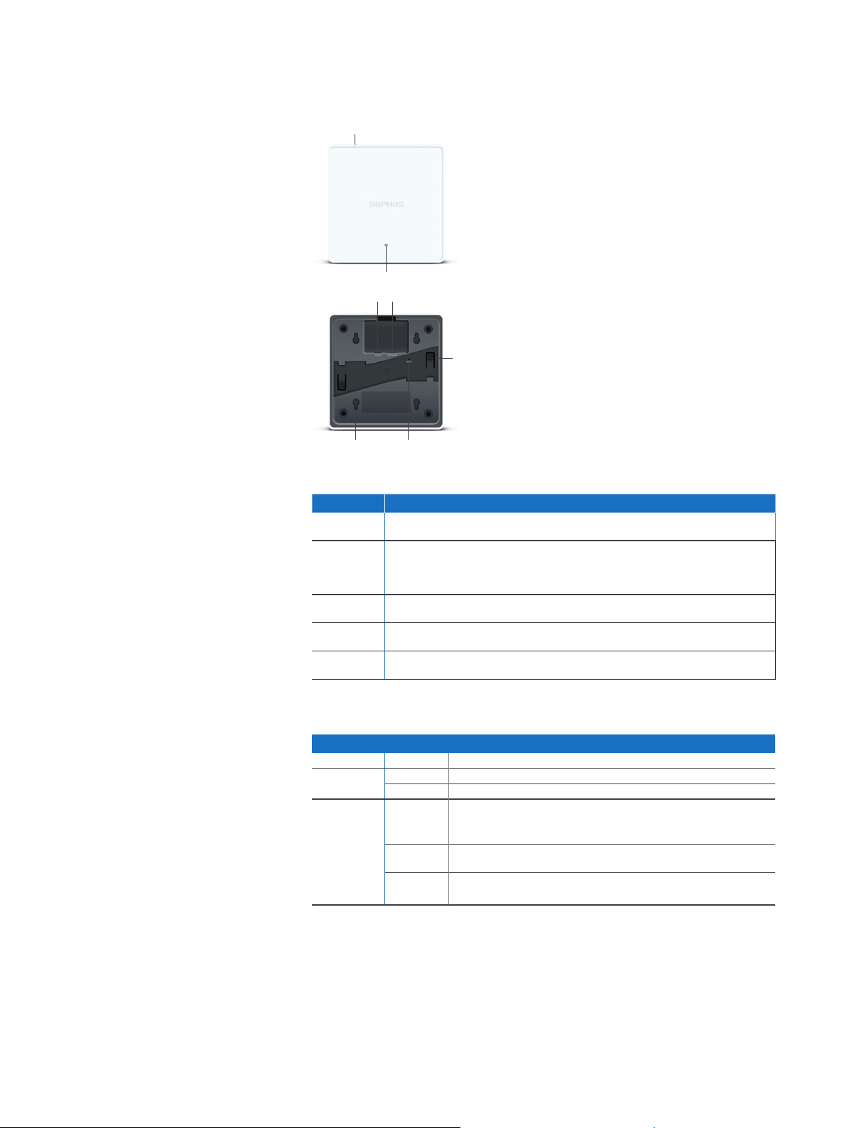
Operating Elements and Connections
APX 120
Kensington Lock
LED
Power connector
LAN (PoE) Port
15/16" T-bar &
flat ceiling bracket
connectors
Wallmount
keyholes
Reset
button
Component Descriptions
Component Description
Status LED The Status LED indicates the operational state of your access point such as boot
Eth0 (PoE) Eth0 is the Ethernet port to connect your access point to your network. This port
Power
Connector
Reset button The reset button allows you to reboot the device and reset its configuration
Kensington
Lock
status, firmware updates and error states. For details, see table “LED Status” below.
can also be connected to a PoE capable source (PoE Injector or PoE switch) to
power your access point. Alternatively, you can power the access point using an
APX 120 Power Supply (available as an accessory from your Sophos partner).
If you are not using PoE as a power source you can connect
an optionally available APX 120 Power supply here.
to the factory default. For details, please see section “Reboot & Reset”
You can physically secure the AP by attaching a lock and cable (such
as a Kensington® notebook lock) to the device lock slot.
LED Status
LED on Front
Off Off AP is off or reboot started
Green Solid Normal operation
Flashing AP is booting & connecting to wireless controller
Red Solid Error, no wireless controller found. AP will reboot (if not yet claimed
by a controller). Check network connection if error persists.
If reset button pressed: AP preparing configuration reset
Flashing
Configuration reset in progress
*
slowly
Flashing
fast
* Your AP should recover from this state after a maximum of 5 minutes.
Firmware update in progress
Note: Do not disconnect from power
*
*
2APX 120
Page 4
Operating Instructions
Connection and Configuration
The initial connection of your access point to your network and the wireless
controller is described in the APX Quick Start Guide which was been shipped with
your device or is available under www.sophos.com/get-started-ap.
For the access point to communicate with Sophos Central servers the following
ports will need to be open on your firewall:
Ì 443 (HTTPS)
Ì 80 (HTTP)
Ì 123 (NTP)
After successful connection you can start your initial configuration.
Setting up your access point in Sophos Central
You will need a Sophos Central account to manage your access points. Please
go to https://central.sophos.com to sign in under your account or create a new
account.
After signing in select Wireless from the popup screen or click on Wireless in the
left navigation to get started.
Follow the Onboarding Wizard to register your access point.
For more information, please see the Sophos Central Admin Help.
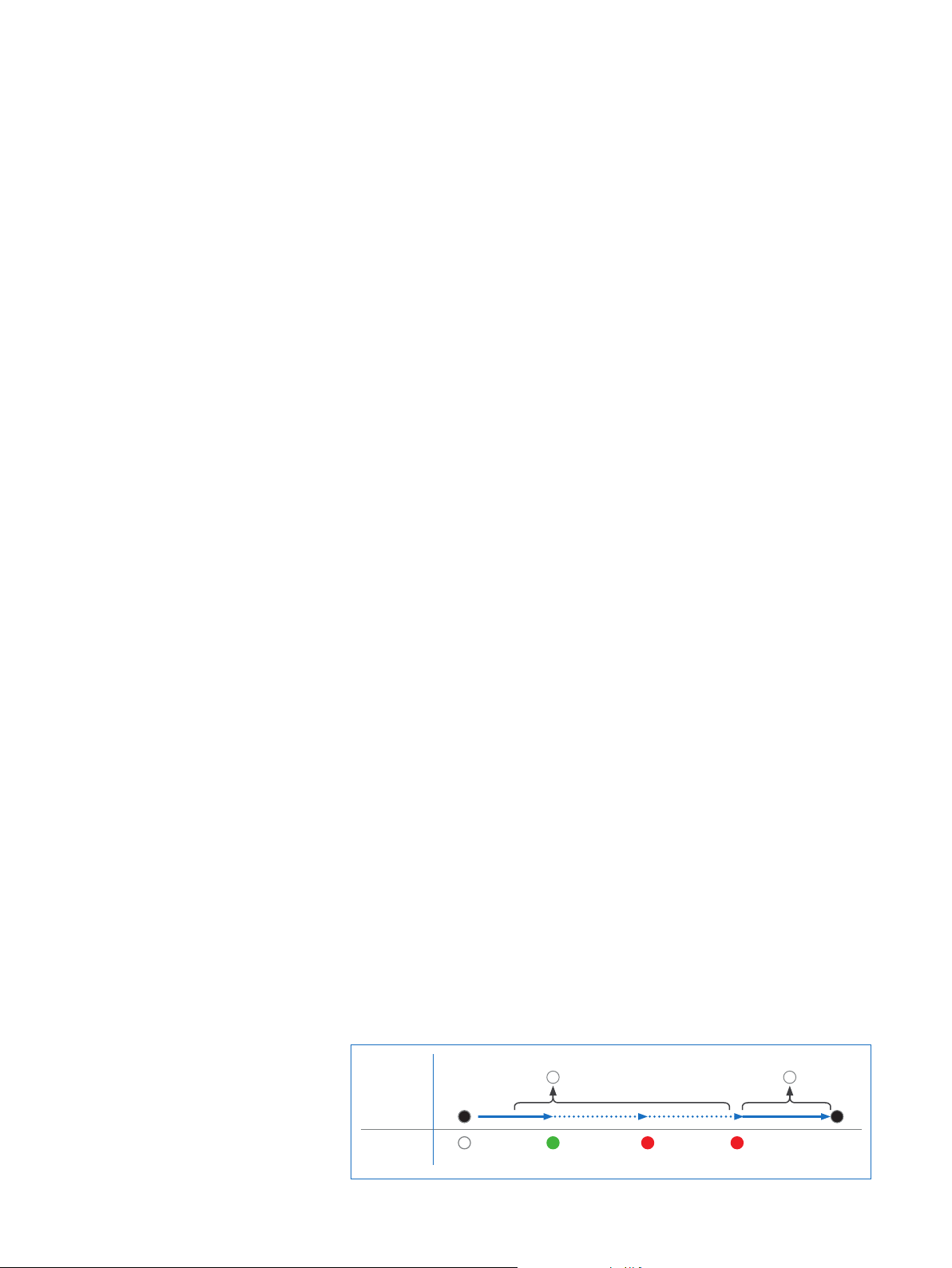
Reboot & Reset
Your access point can be rebooted with the installed configuration or reset to the
factory default configuration depending on how long you press and hold the reset
button.
Reboot with current image and configuration
1. Press reset button
2. Release reset button
3. AP reboots (LED will go off, then will turn to solid green)
Reboot with current image and clear configuration
1. Press and hold reset button
2. AP reboots (LED will go off and then switch to green briefly)
3. LED will turn solid red for 5 sec. You can still cancel
the configuration clearance process by releasing the
reset button before the LED starts blinking
4. LED will blink red (configuration will be cleared)
5. Release reset button
6. AP reboots with factory default settings
Reset
Button
Status LED
Released
Pressed
Off
Reboot Reboot clear config
Solid Solid Blinking
5 Sec
3APX 120
Page 5

Operating Instructions
Technical specifications
APX 120
Environment
Power consumption 11.8 W (max.)
Power over Ethernet
(PoE) requirements
DC Power Supply 12V/1A
Operating temperature 0°-40° C
Storage temperature -40°-80° C
Humidity 10-95% non-condensing
Hazardous substances RoHS-2 and REACH compliant
Physical specification
I/O ports 1x RJ45 10/100/1000 Ethernet w/PoE (802.3af)
Memory 256 MByte DDR3
Mounting Desktop
Dimensions
(Width x Depth x Height)
Weight 256g
Wireless specification
Radios 1x 2.4 GHz single band
Antennas 2x internal dual band antennas
MIMO capabilities 2x2 MIMO at 2.4 GHz, and 2x2 MU-MIMO (802.11ac Wave 2) at 5 GHz
Supported WLAN standards IEEE 802.11 a/b/g/n/ac
SSIDs 8 per radio, 16 in total
Max. throughput 867Mbps (5 G) + 300Mbps (2.4 G)
802.3af
1x Reset button
1x Kensington security slot
256 Mbyte NAND Flash
2 Mbyte SPI NOR Flash
Wall-mount hang
Ceiling (15/16 T-bar, flat ceiling)
144x144x33.5 mm
1x 5 GHz single band
Antenna peak gain: 3.7 dBi at 2.4 GHz / 4.2 dBi at 5 GHz
4APX 120
Page 6

Operating Instructions
Transmit and Receive Power TX Power RX Sensitivity
Mode
2.412-2.472 GHz
(11b)
2.412-2.472 GHz
(11g)
2.412-2.472 GHz
(11n HT20)
5.180-5.825 GHz
(11a)
5.180-5.825 GHz
(11ac VHT20)
5.180-5.825 GHz
(11ac VHT40)
5.180-5.825 GHz
(11ac VHT80)
Bandwidth Maximum
EIRP (dBm)
1 Mbps 22 -98
2 Mbps 22 -95
5.5 Mbps 23 -93
11 Mbps 23 -90
6 Mbps 23 -92
9 Mbps 23 -91
12 Mbps 23 -90
18 Mbps 23 -88
24 Mbps 23 -85
36 Mbps 22 -82
48 Mbps 21 -77
54 Mbps 20 -76
MCS 0 23 -92
MCS 1 22 -90
MCS 2 22 -88
MCS 3 22 -85
MCS 4 22 -82
MCS 5 22 -7 8
MCS 6 22 -76
MCS 7 21 -75
MCS 8 19 -70
6 Mbps 23 -91
9 Mbps 23 -90
12 Mbps 23 -89
18 Mbps 23 -87
24 Mbps 23 -84
36 Mbps 23 -81
48 Mbps 22 -76
54 Mbps 22 -75
MCS0 23 -91
MCS1 23 -88
MCS2 23 -87
MCS3 23 -83
MCS4 23 -81
MCS5 23 -76
MCS6 22 -75
MCS7 22 -7 3
MCS8 22 -69
MCS0 23 -88
MCS1 23 -86
MCS2 23 -84
MCS3 23 -81
MCS4 22 -76
MCS5 22 -74
MCS6 21 -72
MCS7 21 -70
MCS8 20 -66
MCS9 20 -65
MCS0 23 -84
MCS1 23 -83
MCS2 23 -81
MCS3 23 -77
MCS4 21 -75
MCS5 21 -7 1
MCS6 21 -69
MCS7 21 -68
MCS8 19 -64
MCS9 19 -61
(dBm)
5APX 120
Page 7

Operating Instructions
Radiation patterns
2.4 G Band
0
6
355
349
343
338
332
326
321
315
310
304
298
293
287
281
276
270
265
259
253
248
242
236
231
225
219
214
208
203
197
191
11
17
23
10
5
0
-5
-10
-15
-20
-25
-30
-35
-40
186
180
28
34
39
141
146
152
158
163
169
174
-150
-145
45
51
56
62
68
73
79
84
90
96
101
107
113
118
124
129
135
-140
-135
-130
-125
-120
-115
-110
-105
-100
-95
-90
-85
-80
-75
-70
-65
-60
-55
-50
-45
-40
-35
2.45 GHz Horizontal (XY) 2.45 GHz Elevation (YZ)
-175
-170
-165
-160
10
5
0
-5
-10
-15
-20
-25
-30
-35
-40
-30
-25
-20
-15
-10
5 G
0
6
355
349
343
338
332
326
321
315
310
304
298
293
287
281
276
270
265
259
253
248
242
236
231
225
219
214
208
203
197
191
11
17
23
10
5
0
-5
-10
-15
-20
-25
-30
-35
-40
186
180
28
34
39
141
146
152
158
163
169
174
-150
-145
45
51
56
62
68
73
79
84
90
96
101
107
113
118
124
129
135
-140
-135
-130
-125
-120
-115
-110
-105
-100
-95
-90
-85
-80
-75
-70
-65
-60
-55
-50
-45
-40
-35
-175
-170
-165
-160
10
5
0
-5
-10
-15
-20
-25
-30
-35
-40
-30
-25
-20
-15
-10
180
175
170
165
160
155-155
150
145
140
135
130
125
120
115
110
105
100
95
90
85
80
75
70
65
60
55
50
45
40
35
30
25
20
15
10
50-5
180
175
170
165
160
155-155
150
145
140
135
130
125
120
115
110
105
100
95
90
85
80
75
70
65
60
55
50
45
40
35
30
25
20
15
10
50-5
5.55 GHz Horizontal (XY) 5.55 GHz Elevation (YZ)
6APX 120
Page 8

Operating Instructions
Mounting instructions
There are various mounting options available allowing you to hang your access
point on the wall or mount it to various ceiling types. The following sections
provide detailed instructions for the various options which are available today
Your APX 120 supports the following mounting options:
Ì Wall mount hang
Ì Ceiling mount for 15/16” ceiling track, flush ceiling tiles
Ì Flat ceiling mount (by using the supplied mounting bracket)
APX 120 Mounting template
Do not shrink to fit when printing
7.55cm (2.79in)
7APX 120
Page 9

Operating Instructions
Wall mount
You can either hang the unit on the wall by using the wall mount keyholes on the
rear of the unit or by using the supplied mounting bracket.
The following procedure explains how to use the keyholes. The use of the
mounting bracket is described within the section “flat ceiling mount”.
6.7mm ±2.0
Wall
Wall Wall
Mounting instructions
1. Use the wall mount template to mark the screw
mounting positions on the wall.
2. Drill the 2 supplied wall anchors into the wall at the marked positions and
screw the 2 supplied screws into them. Make sure they stand out ~6.7mm.
3. Hang the access point on the wall by aligning the
key holes with the mounted screws.
8APX 120
Page 10

Operating Instructions
Ceiling mount for 15/16” ceiling track, flush ceiling tiles
You can directly attach your APX 120 to a 15/16” ceiling track by using the
integrated connectors on the rear of the unit.
Mounting instructions
1. To install, put the access point underneath the
ceiling rail and turn it into place.
2. To dismount, push down the spring locks and turn
the access point in the other direction.
Flat ceiling mount
For flat ceiling mount please use the supplied mounting bracket. This can also be
used as an alternative method for wall mount hang.
Mounting instructions
1. Use the main bracket as a template to mark the
screw mounting positions on the wall
2. Mount the bracket on the wall or ceiling by using the four
dowel and screws within the scope of supply.
3. Find the marking line on the bracket.
4. Place the access point above the bracket and align the left-hand
side of the access point with the marking on the bracket.
5. Slightly push the access point and gently slide
it to the left until it snaps into place.
6. To unmount, gently slide the access point to the right.
9APX 120
Page 11

Operating Instructions
United Kingdom and Worldwide Sales
Tel: +44 (0)8447 671131
Email: sales@sophos.com
© Copyright 2018. Sophos Ltd. All rights reserved.
Registered in England and Wales No. 2096520, The Pentagon, Abingdon Science Park, Abingdon, OX14 3YP, UK
Sophos is the registered trademark of Sophos Ltd. All other product and company names mentioned are
trademarks or registered trademarks of their respective owners.
18-11-22 OINA (DD)
North American Sales
Toll Free: 1-866-866-2802
Email: nasales@sophos.com
Australia and New Zealand Sales
Tel: +61 2 9409 9100
Email: sales@sophos.com.au
Asia Sales
Tel: +65 62244168
Email: salesasia@sophos.com
 Loading...