

Page 1

Working Instruction, Electrical
Working Instruction, Electrical
Applicable for W960
CONTENTS
1 Read this first!........................................................................................3
2 Lead-free soldering................................................................................4
3 Hot air gun temperature requirements.................................................6
4 Soldering tip temperature requirements..............................................6
5 Bottom heat requirements.....................................................................6
6 BGA equipment reflow profiles.............................................................6
6.1 General..................................................................................................6
6.2 Temperature Measurements................................................................. 6
7 PoP Components Repair instruction....................................................8
8 Shield fence instruction.......................................................................12
9 Replacement of components ..............................................................13
9.1 B2000 Quartz/Crystal 32768Hz..........................................................14
9.2 B2500 Quartz/Crystal 32768MZ.........................................................14
9.3 B2510 Crystal 13 MHz .......................................................................15
9.4 B2680 12.000 MHz Crystal osc..........................................................15
9.5 B6000 Crystal 44 MHz .......................................................................16
9.6 D1100 Marlin...................................................................................... 16
9.7 D2005 Asic Wanda 10X10.................................................................17
9.8 D2500 Suzi PoP................................................................................. 17
9.9 D2501 2 - ind and gate.......................................................................18
9.10 D2663 USB OTG Transceiver............................................................ 18
9.11 D2665 Asic Elin (Knatte 3)................................................................. 19
9.12 D5001 Microphone.............................................................................19
9.13 D6000 Level Shifter............................................................................20
9.14 N2000 Asic Vincenne2.......................................................................20
9.15 N2662 ESD Protection for USB..........................................................21
9.16 N3001 Bluetooth module....................................................................21
9.17 N4021, N4040 Step-down DC/DC......................................................22
9.18 N4030 2,8V 150mA Line regulator.....................................................22
9.19 N4050 LDO 120mA Line regulator.....................................................23
9.20 N4070 LED Driver.............................................................................. 23
9.21 N4071 Single Gate.............................................................................24
9.22 N5010 Asic Tjatte3.............................................................................24
9.23 N5500 Stereo Headphone Ampl........................................................25
9.24 N5505 Audio Amplifier........................................................................25
9.25 N5508 FM-radio w RDS..................................................................... 26
9.26 N6000 W-Lan Module 802.11b..........................................................26
9.27 S2125, S2821, S2822 Side Push Switch........................................... 27
9.28 S2820 Jog Dial...................................................................................27
1206-4806 Rev1 Approved according to 000 21-LXE 107 42/ 1
© Sony Ericsson Mobile Communications AB
Page 2

Working Instruction, Electrical
9.29 V2125, V4001, V5000, V5001 Diode, SSM Series ............................28
9.30 V2181, V2191 Dual Red/Green SMD.................................................28
9.31 V2663 ESD Protector 5,6V.................................................................29
9.32 V4004 Diode, Shottky.........................................................................29
9.33 X1001 External RF Connector...........................................................30
9.34 X10¹⁰, X1011, X1012, X6001 Internal antenna connector................ 30
9.35 X10²¹ Connector...............................................................................31
9.36 X2741 Connector 22pin BtB...............................................................31
9.37 X2743 Camera Socket....................................................................... 32
9.38 X2820 Display Connector...................................................................32
9.39 X2821 Keyboard Connector...............................................................33
9.40 X2825 Spring Connector, 5 Pins........................................................33
9.41 X3001, X6000 Antenna Switch........................................................... 34
9.42 X4000 Battery Connector...................................................................34
10 Revision history ...................................................................................35
1206-4806 Rev1 2(35)
© Sony Ericsson Mobile Communications AB
Page 3

Working Instruction, Electrical
1 Read this first!
CAUTION
Before you start replacing any components, make sure you have read and fully understood
the contents of section 2 and 3!
• Also make sure you have acces
listed on the first page of section 4!
• Use Electrostatic Discharge (ESD) equipment to avoid damaging the PBA.
• Use gloves or finger cots to avoid contaminating the PBA with skin oil.
s to the mechanical Working Instruction and the equipment
1206-4806 Rev1 3(35)
© Sony Ericsson Mobile Communications AB
Page 4
Working Instruction, Electrical
2 Lead-free soldering
KEEP ALL CONTACT SURFACES CLEAN OF DIRT AND HAND
GREASE
!
THIS PRODUCT IS MANUFACTURED WITH LEAD-FREE SOLDER
AND LEAD
-FREE COMPONENTS!
During electrical repair, it is critical to make sure that no
lead is in
troduced.
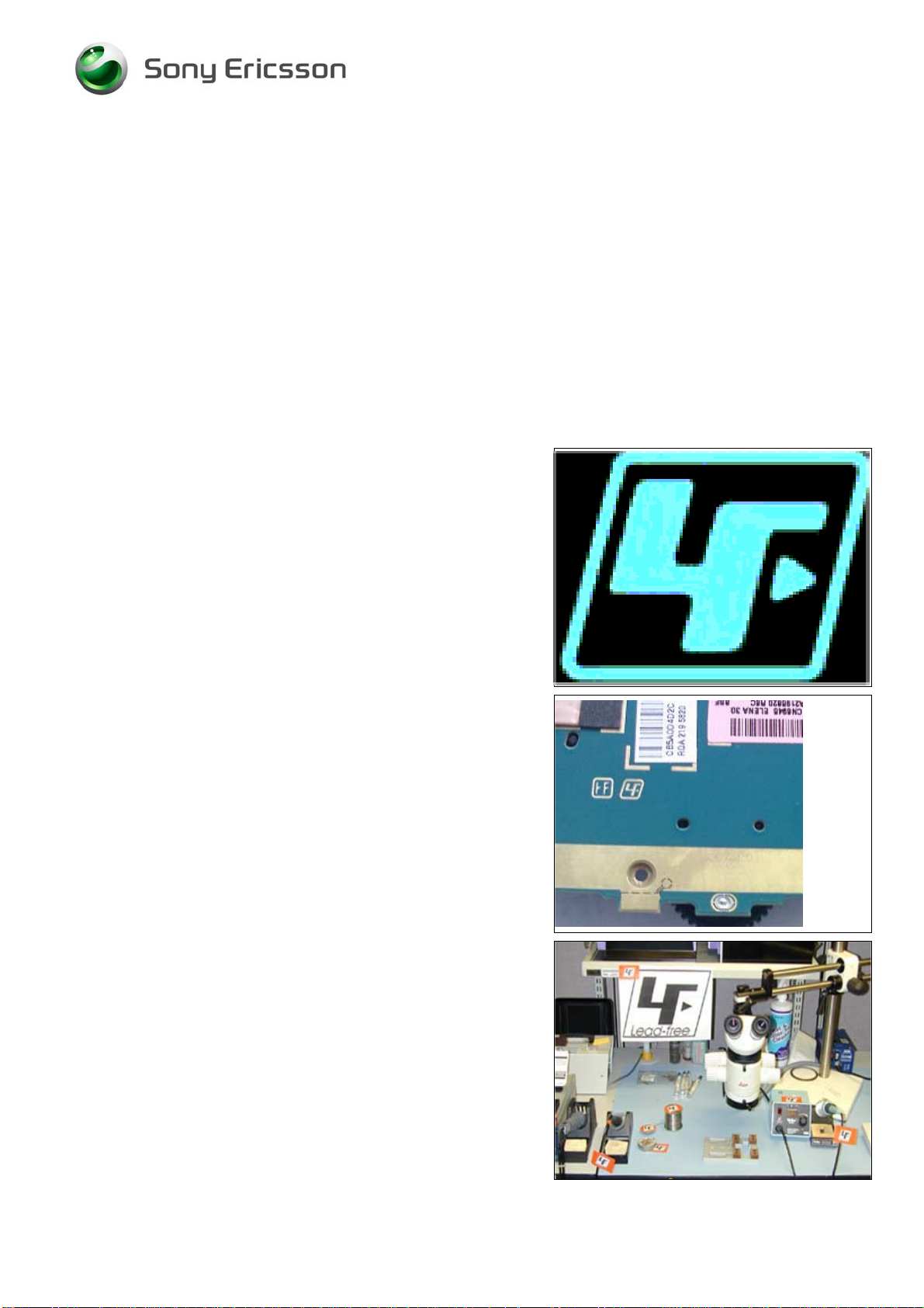
This symbol indicates that the product is lead- free.
All lead-free PBA will be marked with this symbol.
A lead-free work area must be set up completely separated
from work areas that are used to make lead repairs.
The lead-free work area must also be clearly labeled with
the lead free
symbol as shown in the adjacent picture.
The items on this desk must remain lead-free.
They must be adequately labeled to make their lead-free
status clearly and easily recognized.
1206-4806 Rev1 4(35)
© Sony Ericsson Mobile Communications AB
Page 5
Working Instruction, Electrical
Lead-free soldering continued
LFS (lead-free solder paste) characteristics:
• High melting point (typically 220°C)
• Low wettability
• High surface tension
• Difficult to spread
• Recommended tip temperature = 360°C
WHEN SERVICING PBA’S THAT HAVE BEEN MANUFACTURED
LFS (LEAD-FREE SOLDER PASTE), LFS MUST BE USED.
WITH
I
F NOT, THERE IS A HIGH RISK FOR UNRELIABLE SOLDERING
JOINTS
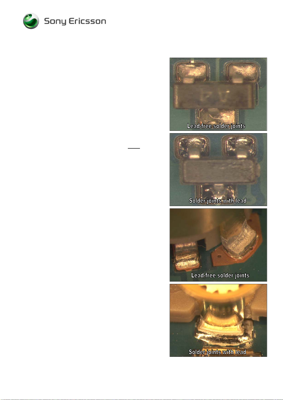
Lead-free solder joints are more difficult to inspect because
they do not have shiny surfaces like leaded solde
Also, lead-free solder does not flow as well as leaded
solder, so
exposed.
.
r joints.
some of the solder pad areas may remain
1206-4806 Rev1 5(35)
© Sony Ericsson Mobile Communications AB
Page 6

Working Instruction, Electrical
3 Hot air gun temperature requirements
The air temperature shall not exceed 360°C. The temperature shall be measured 5 mm from
the nozzle outlet.
If it’s not possible to remove and/ or solder with 360°C a BGA Rework Station or another
repair process shall be considered to ensure high process control.
Too high temperature can cause damage and cracks due to therm
components, e.g. ceramic components like capacitors.
4 Soldering tip temperature requirements
The soldering tip temperature shall be minimum 310°C and maximum 360°C.
Too high temperature can cause damage and cracks due to therm
components, e.g. ceramic components like capacitors.
5 Bottom heat requirements
In the chapter 8 “Replacement of components” there are components which require to us a
bottom heater during repair to pre-heat the board and to level out the ∆T on the PBA. It will
also minimize thermal stress.
The temperature on the PBA surface shall not exceed
growth and thermal stress on PWB.
150°C to minimize inter-metallic
al stress on sensitive
al stress on sensitive
6 BGA equipment reflow profiles
6.1 General
BGA Rework Station shall be able to control time, airflow and temperature to achieve
controlled and stable reflow profile. It shall also have a temperature controlled bottom heater.
The profile shall be according to SEMC profiling specification below.
Profile parameters are illustrated in table 6.1.1.
Reflow profile in this document always refers to the reflow profile which is
with thermocouples and do not refer to the BGA Rework Stations setting which can vary depending on the
machine type and individual machine. Verification of reflow profile shall be done on each set of equipment.
Reference profile is showed in table 6.2
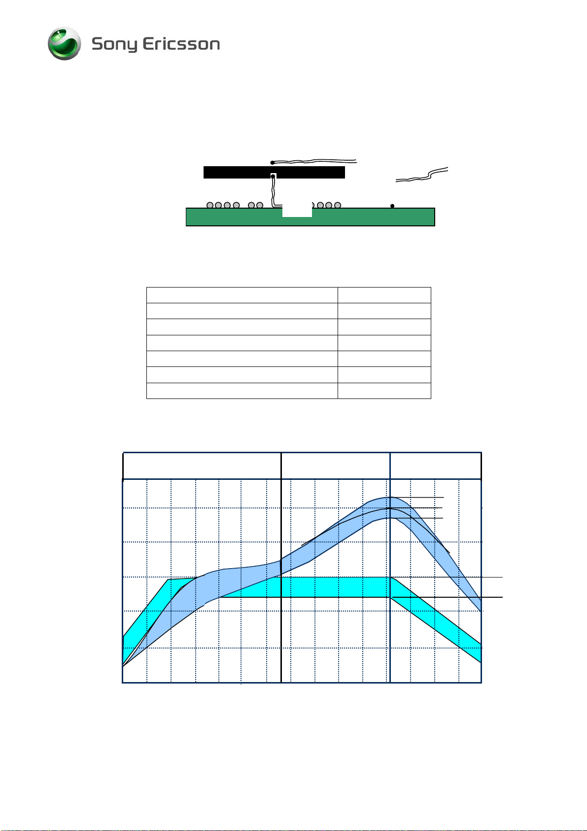
6.2 Temperature Measurements
One thermocouple shall be located in the middle of the component (Thermocouple # 1). It
shall be drilled from bottom side and located at the ball. The hole shall be filled with glue. A
slot could also be milled in the PWB to locate the thermocouple under the component. See
picture 6.1.
The other thermocouple (Thermocouple # 2) should be attached in the center and on the top
of the component body; it shall be attached with thin heat resistant tape or a thin layer of glue.
Too thick layer of glue will isolate too much heat which could give uncertain measurements.
measured on the board/component
1206-4806 Rev1 6(35)
© Sony Ericsson Mobile Communications AB
Page 7
Working Instruction, Electrical
It’s also recommended to place thermocouples on adjacent components to make sure that they
are not over exposed to the heat.
Picture 6.1
# 2
# 3 (Recommended)
# 1
Table 6.1.1
Ramp rate < 3°C/sec
Ramp rate cooling < 6°C/sec
Time above liquidus 40-70 sec
Minimum temperature 235°C
Maximum component temperature 260 °C
Time above 235°C 10-40 sec
Recommended Total time Approx. 3-5min
* The higher temperature in case the board has extremely high ΔT.
Table 6.2
290
250
Reflow zone
260°C
245°C
235°C
200
150
Temperature [ºC]
100
150°C
125°C
50
0
40 80 120 160
Time [Seconds]
200
240 280
1206-4806 Rev1 7(35)
© Sony Ericsson Mobile Communications AB
Page 8
Working Instruction, Electrical
7 PoP Components Repair instruction
1. Scope of the work instruction
2. Description
3. Preparation
4. Process instruction
4.1 Needed equipment and tools
4.2 Process description
5. Work instruction
5.1 Removing
5.2 Soldering removal
5.3 Inspection
5.4 Assembly and re soldering
5.5 Inspection after repair
6. Revision History
1. Scope of the work instruction
This document was created to help and guide the repair operators to replace the PoP
components and to avoid mistakes and misunderstandings during the repair process and to
avoid any damage to the final product.
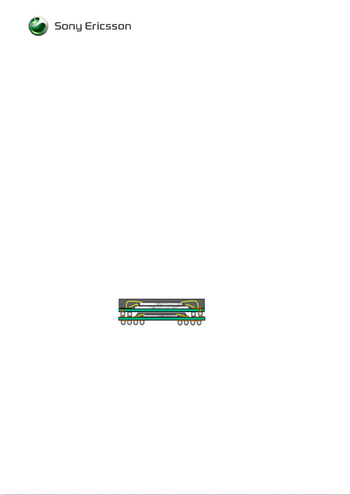
2. Description
PoP component is a new type of BGA component which is made by two components,
CPU on bottom and Memory soldered directly on the top of CPU, see picture below.
PoP component (Package-on-Package).
Fig 1: Cross-sectional view of the PoP stack.
Bottom package: CPU( Suzi/ Anja).
Top package: Memory NAND/SDRAM
Example of PoP components used in P1i is D2500, the PDA processor with memory.
3. Preparation
Before starting the repair action, be sure that:
• You have trained to use BGA rework station
• You have the necessary tools
• You have correct components (type and revision)
• You are ESD protected
1206-4806 Rev1 8(35)
© Sony Ericsson Mobile Communications AB
Page 9
Working Instruction, Electrical
4. Process instruction
4.1 Needed equipment and tools
• BGA rework station
• Adequate Reflow profile for component
• Adequate Nozzle
• Soldering iron
• Hot air station
• Tweezers
• De-soldering wick
• Flux
4.2 Process description
BGA rework station is using to solder and de solder PoP component. Be sure that correct
soldering head (Nozzle) and correct temperature profile is used.
Soldering iron, hot air station, flux and de-soldering wick are used to remove the soldering
rest of the PCB after the old component has been removed.
5. Work instruction
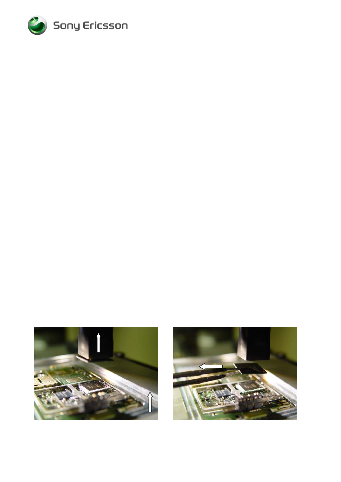
5.1 Removing
This instruction is showing how to remove the PoP component in one heating cycle.
Equipment used A: Finetech CRS 10, Fine placer.
B: OKI, BGA station
Other similar BGA station can be use.
5.1A
Put the board in the fixture, chose the right nozzle and temperature profile.
Align the nozzle to the component and start the de-soldering program.
When the temperature is coming to the melting point activate the vacuum, the memory
will be removed from the CPU (picture A1), lift the nozzle for a few centimeters and
remove the memory from the nozzle using tweezers (picture A2). Put the nozzle down
again, readjust the distance to the CPU, and wait for a couple of seconds and remove the
CPU component too (picture A3). Wait for the cooling down time, and remove the PCB
from the fixture and go to next step.
Picture A1 Picture A2
1206-4806 Rev1 9(35)
© Sony Ericsson Mobile Communications AB
Page 10
Working Instruction, Electrical
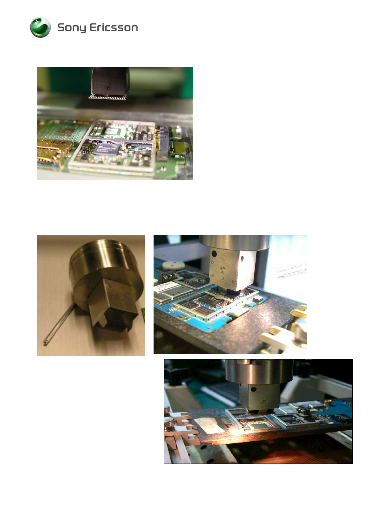
Picture A3
5.1B
Using a special designed nozzle with mechanical grips (picture B1) will be possible to
remove only the top component (memory), ort both components in the same time (picture
B2 and B3)
Picture
B1
Picture
B2
Picture B3
1206-4806 Rev1 10(35)
© Sony Ericsson Mobile Communications AB
Page 11

Working Instruction, Electrical
5.2 Soldering removal
The landing area has to be cleaned from old soldering and flux.
5.3 Inspection
Check under the microscope that are no damage happened to mask, pads or the
surrounding components. Go to next step.
5.4 Assembly and re soldering
Put the board in the stations fixture, chose the adequate nozzle and reflow profile.
Check the component revision and mounting direction. Add flux on the board and on the
CPU top pads.
Pick up the CPU and align it to the board and put it down.
Pick up the memory and align it to the CPU, and put the component on the top of the
other component.
Start the reflow profile.
5.5 Inspection after repair
After soldering check the board to be sure that no other components are damaged or
removed. Inspect component by X-ray and send the board to trouble shoot station for
test.
Each time PCB assemblies have been repaired it shall be marked with an indication on the
PCB .
1206-4806 Rev1 11(35)
© Sony Ericsson Mobile Communications AB
Page 12

Working Instruction, Electrical
8 Shield fence instruction
This instruction shows how to cut and bend the shield can
fence to be able to replace components under the fence.
Use a sharp-edged pliers to cut the fence.
Use Shield fence pliers NTZ 112 537 to bend the fence.
MAKE SURE THAT CUTTING PLIERS IS SHARP-EDGED TO
PREVENT DAMAGING THE SHIELD CAN FENCE
Remove the shield can lid, use a dentist hook.
Remove the pick up area according to the white lines with
a cutting plier. (1)
This pick up area is only used when machine mounting
and there is
Cut the shield can fence according to the white lines with
a cutting plier. (2)
no need to put it back again.
.
Carefully bend the shield fence with a shield fence plier.
Replace the components.
Replace the components.
Bend carefully back the shield fence.
Put back a new
Press on all sides of the lid until you hear a “click” sound.
1206-4806 Rev1 12(35)
shield can lid.
© Sony Ericsson Mobile Communications AB
Page 13

Working Instruction, Electrical
9 Replacement of components
EQUIPMENT
• Dentist hook
• Shield fence pliers NTZ 112 537
• Hot air soldering equipment
• Soldering iron
• BGA repair equipment
• Pair of tweezers
• Soldering cleaning wiper (tin wick)
• Solder paste lead-free (SN 96% AG 3.5% Cu 0.5 %
• Flux, RMA no-clean flux
• Cutting pliers
CAUTION
Keep all contact surfaces clean, no dirt or hand grease!
Protect the phone from ESD damages whenever it has been opened by using:
• ESD-wristb
• ESD-gloves
•
MECHANICAL INSTRUCTIONS
For all the following part replacements, disassemble and assemble the phone as described in
Working Instruction 1206-4797.
and
1206-4806 Rev1 13(35)
© Sony Ericsson Mobile Communications AB
Page 14

Working Instruction, Electrical
9.1 B2000 Quartz/Crystal 32768Hz
MAKE SURE THAT CUTTING PLIERS IS SHARP-EDGED TO
PREVENT DAMAGING THE SHIELD CAN FENCE
.
Remove the shield can lid, use a dentist hook.
Remove the pick up area according to the white lines with
a cutting plier.
This pick up area doesn’t have to be replaced.
Replace the Quartz/Crystal 32768Hz.
Use Hot air repair equipment.
Put back a new
shield can lid.
Press on all sides of the lid until you hear a “click” sound.
9.2 B2500 Quartz/Crystal 32768MZ
Remove the shield can lid.
Use a dentist hook.
Replace the Quartz/Crystal 32768Hz.
Use Hot air repair equipment.
Put back a new
Press on all sides of the lid until you hear a “click” sound.
shield can lid.
1206-4806 Rev1 14(35)
© Sony Ericsson Mobile Communications AB
Page 15

Working Instruction, Electrical
9.3 B2510 Crystal 13 MHz
Remove the shield can lid.
Use a dentist hook.
Replace the Crystal 13MHz.
Use BGA repair equipment.
Put back a new
shield can lid.
Press on all sides of the lid until you hear a “click” sound.
9.4 B2680 12.000 MHz Crystal osc
MAKE SURE THAT CUTTING PLIERS IS SHARP-EDGED TO
PREVENT DAMAGING THE SHIELD CAN FENCE
.
Remove the shield can lid, use a dentist hook.
Remove the pick up area according to the white lines with
a cutting plier.
This pick up area doesn’t have to be replaced.
Replace the 12.000 MHz Crystal osc.
Use Hot air repair equipment.
Put back a new
shield can lid.
Press on all sides of the lid until you hear a “click” sound.
1206-4806 Rev1 15(35)
© Sony Ericsson Mobile Communications AB
Page 16

Working Instruction, Electrical
9.5 B6000 Crystal 44 MHz
Remove the shield can lid.
Use a dentist hook.
Replace the Crystal 44 MHz.
Use Hot air repair equipment.
Put back a new
shield can lid.
Press on all sides of the lid until you hear a “click” sound.
9.6 D1100 Marlin
Replace the Marlin.
Use BGA repair equipment.
1206-4806 Rev1 16(35)
© Sony Ericsson Mobile Communications AB
Page 17

Working Instruction, Electrical
9.7 D2005 Asic Wanda 10X10
MAKE SURE THAT CUTTING PLIERS IS SHARP-EDGED TO
PREVENT DAMAGING THE SHIELD CAN FENCE
.
Remove the shield can lid, use a dentist hook.
Remove the pick up area according to the white lines with
a cutting plier.
This pick up area doesn’t have to be replaced.
Replace the Asic Wanda.
Use BGA repair equipment.
Put back a new
shield can lid.
9.8 D2500 Suzi PoP
Use BGA repair equipment.
See chapter 4. PoP components repair instruction
1206-4806 Rev1 17(35)
© Sony Ericsson Mobile Communications AB
Page 18

Working Instruction, Electrical
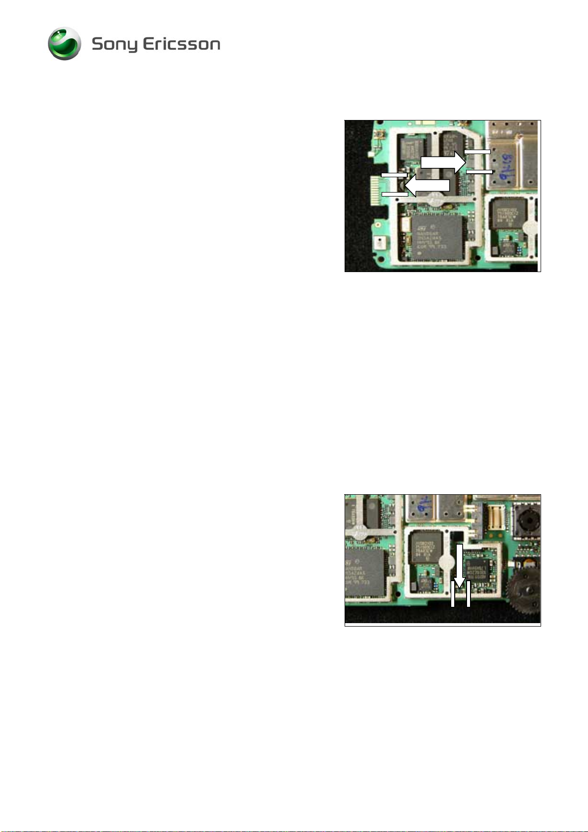
9.9 D2501 2 - ind and gate
MAKE SURE THAT CUTTING PLIERS IS SHARP-EDGED TO
PREVENT DAMAGING THE SHIELD CAN FENCE
.
Remove the shield can lid, use a dentist hook.
Remove the pick up area according to the white lines with
a cutting plier.
This pick up area doesn’t have to be replaced.
Replace the 2 – ind and gate.
Use Hot air repair equipment.
Put back a new
shield can lid.
9.10 D2663 USB OTG Transceiver
MAKE SURE THAT CUTTING PLIERS IS SHARP-EDGED TO
PREVENT DAMAGING THE SHIELD CAN FENCE
.
Remove the shield can lid, use a dentist hook.
Remove the pick up area according to the white lines with
a cutting plier.
This pick up area doesn’t have to be replaced.
Replace the USB OTG Transceiver.
Use BGA repair equipment.
Put back a new
shield can lid.
Press on all sides of the lid until you hear a “click” sound.
1206-4806 Rev1 18(35)
© Sony Ericsson Mobile Communications AB
Page 19

Working Instruction, Electrical
9.11 D2665 Asic Elin (Knatte 3)
Remove the shield can lid.
Use a dentist hook.
Replace the Asic Elin (Knatte 3).
Use Hot air repair equipment.
Put back a new
Press on all sides of the lid until you hear a “click” sound.
shield can lid.
9.12 D5001 Microphone
Replace the Microphone.
Use BGA repair equipment.
1206-4806 Rev1 19(35)
© Sony Ericsson Mobile Communications AB
Page 20

Working Instruction, Electrical
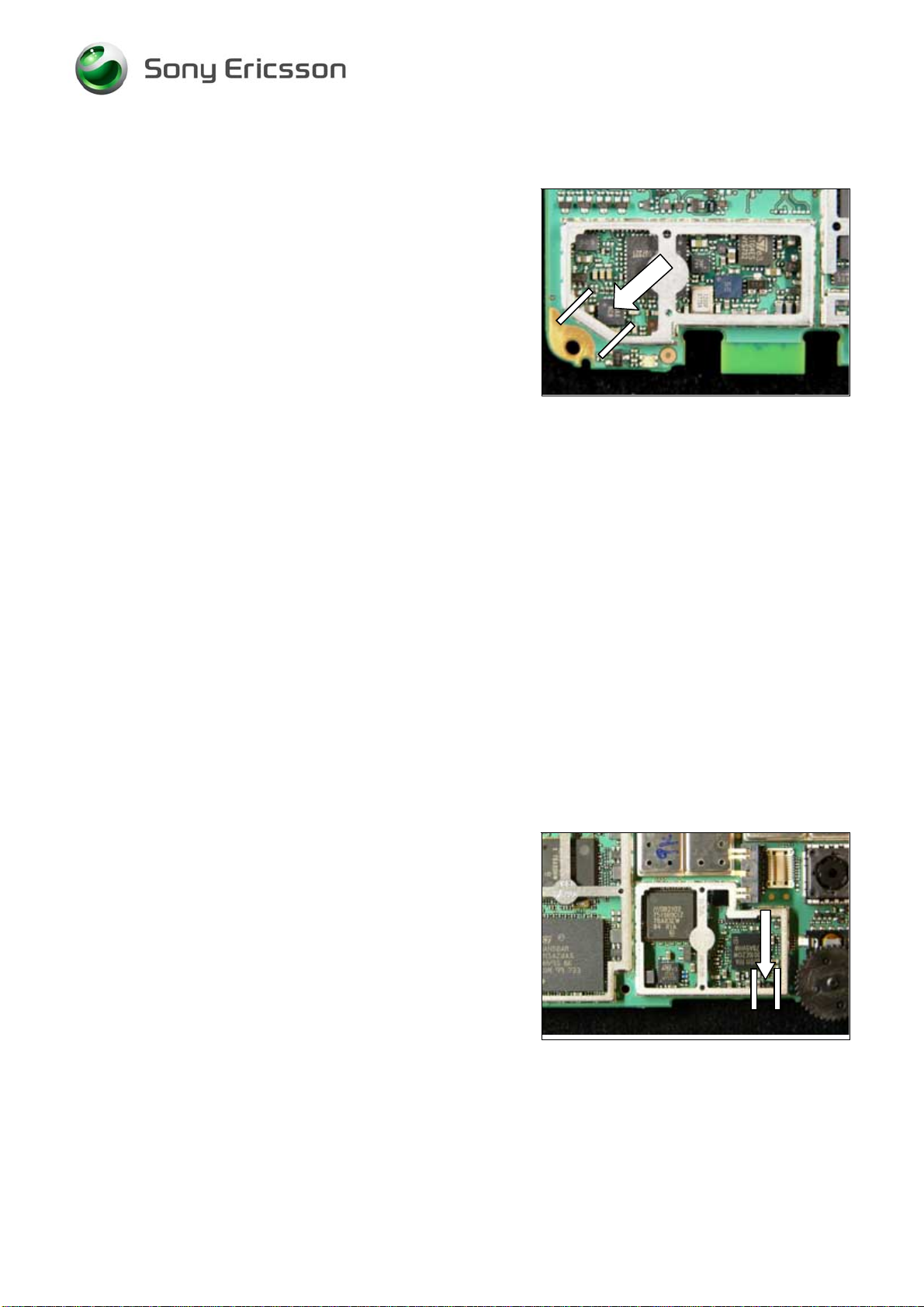
9.13 D6000 Level Shifter
MAKE SURE THAT CUTTING PLIERS IS SHARP-EDGED TO
PREVENT DAMAGING THE SHIELD CAN FENCE
.
Remove the shield can lid, use a dentist hook.
Remove the pick up area according to the white lines with
a cutting plier.
This pick up area doesn’t have to be replaced.
Replace the Level Shifter.
Use Hot air repair equipment.
Put back a new
shield can lid.
9.14 N2000 Asic Vincenne2
Remove the shield can lid.
Use a dentist hook.
Replace the Asic Vincenne2.
Use BGA repair equipment.
Put back a new
Press on all sides of the lid until you hear a “click” sound.
shield can lid.
1206-4806 Rev1 20(35)
© Sony Ericsson Mobile Communications AB
Page 21

Working Instruction, Electrical
9.15 N2662 ESD Protection for USB
MAKE SURE THAT CUTTING PLIERS IS SHARP-EDGED TO
PREVENT DAMAGING THE SHIELD CAN FENCE
Remove the shield can lid, use a dentist hook.
Remove the pick up area according to the white lines with
a cutting plier.
This pick up area doesn’t have to be replaced.
Replace the ESD protection for USB.
Use Hot air repair equipment.
Put back a new
shield can lid.
Press on all sides of the lid until you hear a “click” sound.
.
9.16 N3001 Bluetooth module
Remove the shield can lid.
Use a dentist hook.
Replace the Bluetooth module.
Use BGA repair equipment.
Put back a new
Press on all sides of the lid until you hear a “click” sound.
shield can lid.
1206-4806 Rev1 21(35)
© Sony Ericsson Mobile Communications AB
Page 22
Working Instruction, Electrical
9.17 N4021, N4040 Step-down DC/DC
MAKE SURE THAT CUTTING PLIERS IS SHARP-EDGED TO
PREVENT DAMAGING THE SHIELD CAN FENCE
Remove the shield can lid, use a dentist hook.
Remove the pick up area according to the white lines with
a cutting plier.
This pick up area doesn’t have to be replaced.
Replace the Step-down DC/DC Converter.
Use Hot air repair equipment.
Put back a new
shield can lid.
.
9.18 N4030 2,8V 150mA Line regulator
MAKE SURE THAT CUTTING PLIERS IS SHARP-EDGED TO
PREVENT DAMAGING THE SHIELD CAN FENCE
Remove the shield can lid, use a dentist hook.
Remove the pick up area according to the white lines with
a cutting plier.
This pick up area doesn’t have to be replaced.
Replace the 2,8V 150mA Line Regulator.
Use Hot air repair equipment.
Put back a new
shield can lid.
.
1206-4806 Rev1 22(35)
© Sony Ericsson Mobile Communications AB
Page 23

Working Instruction, Electrical
9.19 N4050 LDO 120mA Line regulator
MAKE SURE THAT CUTTING PLIERS IS SHARP-EDGED TO
PREVENT DAMAGING THE SHIELD CAN FENCE
Remove the shield can lid, use a dentist hook.
Remove the pick up area according to the white lines with
a cutting plier.
This pick up area doesn’t have to be replaced.
Replace the LDO 120mA Line regulator.
Use Hot air repair equipment.
Put back a new
shield can lid.
Press on all sides of the lid until you hear a “click” sound.
.
9.20 N4070 LED Driver
MAKE SURE THAT CUTTING PLIERS IS SHARP-EDGED TO
PREVENT DAMAGING THE SHIELD CAN FENCE
Remove the shield can lid, use a dentist hook.
Remove the pick up area according to the white lines with
a cutting plier.
This pick up area doesn’t have to be replaced.
Replace the LED Driver.
Use Hot air repair equipment.
Put back a new
1206-4806 Rev1 23(35)
shield can lid.
© Sony Ericsson Mobile Communications AB
.
Page 24

Working Instruction, Electrical
9.21 N4071 Single Gate
Replace the Single Gate.
Use Hot air repair equipment.
9.22 N5010 Asic Tjatte3
MAKE SURE THAT CUTTING PLIERS IS SHARP-EDGED TO
PREVENT DAMAGING THE SHIELD CAN FENCE
Remove the shield can lid, use a dentist hook.
Remove the pick up area according to the white lines with
a cutting plier.
This pick up area doesn’t have to be replaced.
Replace the Asic Tjatte3.
Use Hot air repair equipment.
Put back a new
shield can lid.
.
1206-4806 Rev1 24(35)
© Sony Ericsson Mobile Communications AB
Page 25
Working Instruction, Electrical
9.23 N5500 Stereo Headphone Ampl.
MAKE SURE THAT CUTTING PLIERS IS SHARP-EDGED TO
PREVENT DAMAGING THE SHIELD CAN FENCE
Remove the shield can lid, use a dentist hook.
Remove the pick up area according to the white lines with
a cutting plier.
This pick up area doesn’t have to be replaced.
Replace the Stereo Headphone Amplifier.
Use Hot air repair equipment.
Put back a new
shield can lid.
.
9.24 N5505 Audio Amplifier
MAKE SURE THAT CUTTING PLIERS IS SHARP-EDGED TO
PREVENT DAMAGING THE SHIELD CAN FENCE
Remove the shield can lid, use a dentist hook.
Remove the pick up area according to the white lines with
a cutting plier.
This pick up area doesn’t have to be replaced.
Replace the Audio Amplifier.
Use BGA repair equipment.
Put back a new
shield can lid.
.
1206-4806 Rev1 25(35)
© Sony Ericsson Mobile Communications AB
Page 26

Working Instruction, Electrical
9.25 N5508 FM-radio w RDS
MAKE SURE THAT CUTTING PLIERS IS SHARP-EDGED TO
PREVENT DAMAGING THE SHIELD CAN FENCE
Remove the shield can lid, use a dentist hook.
Remove the pick up area according to the white lines with
a cutting plier.
This pick up area doesn’t have to be replaced.
Replace the FM-radio w RDS.
Use Hot air repair equipment.
Put back a new
shield can lid.
.
9.26 N6000 W-Lan Module 802.11b
MAKE SURE THAT CUTTING PLIERS IS SHARP-EDGED TO
PREVENT DAMAGING THE SHIELD CAN FENCE
Remove the shield can lid, use a dentist hook.
Remove the pick up area according to the white lines with
a cutting plier.
This pick up area doesn’t have to be replaced.
Replace the W-LAN Module 802.11b.
Use BGA repair equipment.
Put back a new
shield can lid.
.
1206-4806 Rev1 26(35)
© Sony Ericsson Mobile Communications AB
Page 27

Working Instruction, Electrical
9.27 S2125, S2821, S2822 Side Push Switch
Remove Side key switches.
Use Hot air device.
Install new Side key switches.
Use Soldering Iron
NOTE: Use as little flux as possible to place the new
part. Make sure flux does not get on the component
body.
9.28 S2820 Jog Dial
Replace the Jog dial.
Use soldering iron.
1206-4806 Rev1 27(35)
© Sony Ericsson Mobile Communications AB
Page 28
Working Instruction, Electrical
9.29 V2125, V4001, V5000, V5001 Diode, SSM Series
Replace the V2125 Diode, SSM Series.
Use Hot air repair equipment.
MAKE SURE THAT CUTTING PLIERS IS SHARP-EDGED TO
PREVENT DAMAGING THE SHIELD CAN FENCE
Remove the shield can lid, use a dentist hook.
Remove the pick up area according to the white lines with
a cutting plier.
This pick up area doesn’t have to be replaced.
Replace the V4001 Diode, SSM Series.
Use Hot air repair equipment.
Put back a new
shield can lid.
.
Replace the V5000 and V5001 Diode, SSM Series.
Use Hot air repair equipment.
9.30 V2181, V2191 Dual Red/Green SMD
Remove Dual Red/Green SMD.
Use Hot air device.
Install new Dual Red/Green SMD.
Use Soldering Iron
1206-4806 Rev1 28(35)
© Sony Ericsson Mobile Communications AB
Page 29

Working Instruction, Electrical
9.31 V2663 ESD Protector 5,6V
MAKE SURE THAT CUTTING PLIERS IS SHARP-EDGED TO
PREVENT DAMAGING THE SHIELD CAN FENCE
Remove the shield can lid, use a dentist hook.
Remove the pick up area according to the white lines with
a cutting plier.
This pick up area doesn’t have to be replaced.
Replace the ESD Protector 5,6V.
Use Hot air repair equipment.
Put back a new
shield can lid.
.
9.32 V4004 Diode, Shottky
Remove the shield can lid.
Use a dentist hook.
Replace the Diode, Shottky.
Use Hot air repair equipment.
Put back a new
Press on all sides of the lid until you hear a “click” sound.
shield can lid.
1206-4806 Rev1 29(35)
© Sony Ericsson Mobile Communications AB
Page 30

Working Instruction, Electrical
9.33 X1001 External RF Connector
Remove External RF Connector.
Use Hot air device.
Install new External RF Connector.
Use Soldering Iron
9.34 X10¹⁰, X1011, X1012, X6001 Internal antenna connector
Replace the Internal antenna connector.
Use Hot air repair Equipment.
1206-4806 Rev1 30(35)
© Sony Ericsson Mobile Communications AB
Page 31

Working Instruction, Electrical
9.35 X10²¹ Connector
Replace the Connector.
Use Hot air repair equipment.
9.36 X2741 Connector 22pin BtB
Replace the Connector 22pin BtB.
Use Hot air repair equipment.
1206-4806 Rev1 31(35)
© Sony Ericsson Mobile Communications AB
Page 32

Working Instruction, Electrical
9.37 X2743 Camera Socket
Replace the Camera Socket.
Use Hot air repair equipment.
9.38 X2820 Display Connector
Replace the Display Connector.
Use Hot air repair equipment.
1206-4806 Rev1 32(35)
© Sony Ericsson Mobile Communications AB
Page 33

Working Instruction, Electrical
9.39 X2821 Keyboard Connector
Replace the Keyboard Connector.
Use Hot air repair equipment.
9.40 X2825 Spring Connector, 5 Pins
Replace the Spring Connector, 5 pins.
Use Hot air repair equipment.
1206-4806 Rev1 33(35)
© Sony Ericsson Mobile Communications AB
Page 34

Working Instruction, Electrical
9.41 X3001, X6000 Antenna Switch
Remove Antenna Switch.
Use Hot air device.
Install new Antenna Switch
Use Soldering Iron
9.42 X4000 Battery Connector
Replace the Battery connector.
Use BGA repair equipment.
1206-4806 Rev1 34(35)
© Sony Ericsson Mobile Communications AB
Page 35

Working Instruction, Electrical
10 Revision history
Rev. Date Changes / Comments
1 2007-11-29 Initial release
1206-4806 Rev1 35(35)
© Sony Ericsson Mobile Communications AB
 Loading...