

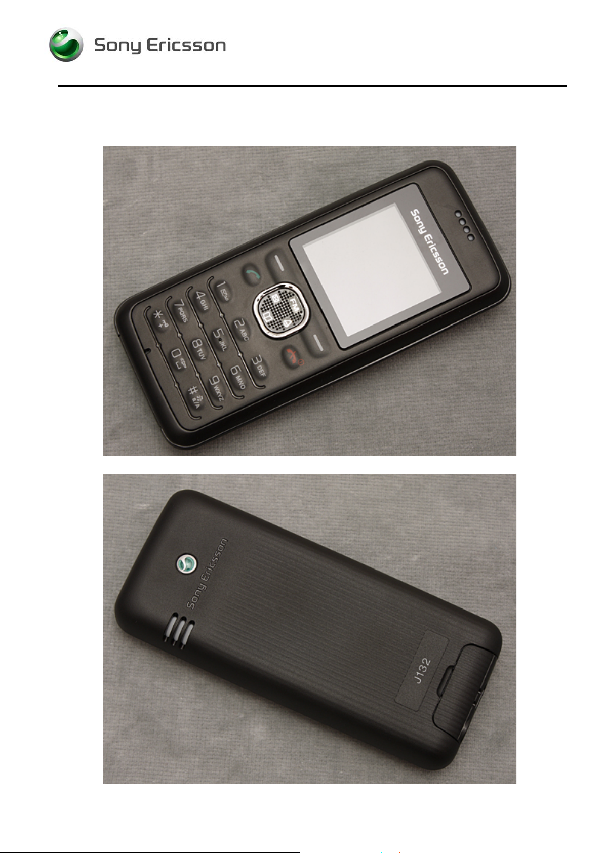
SonyEricsson J132 Service manual

Working Instruction, Mechanical
Working Instruction, Mechanical
Applicable for J132
CONTENTS
1 Introduction ..............................................................................2
1.1 Equipment.................................................................................3
1.2 General cautions......................................................................4
1.3 Adhesives .................................................................................4
2 Disassembly.............................................................................5
2.1 Overview ...................................................................................5
2.1.1 Battery Cover & Battery.................................................................. 6
2.1.2 Front Cover Assembly....................................................................8
2.1.3 PCBA & Back Cover Assembly......................................................9
3 Replacements.........................................................................10
3.1 Battery Cover..........................................................................11
3.2 Front Cover Assembly...........................................................11
3.3 Back Cover Assembly............................................................11
3.4 Dome Foil Assy ......................................................................12
3.5 PCBA Speaker Gasket...........................................................14
3.6 WATERPROOF LABEL ..........................................................15
3.7 Vibrator....................................................................................16
3.8 Speaker ...................................................................................17
3.9 Speaker Cushion....................................................................18
3.10 KRH Label ...............................................................................19
3.11 MICCC......................................................................................20
3.12 Receiver ..................................................................................21
3.13 Receiver Cushion...................................................................22
4 Reassembly ............................................................................23
4.1 Overview .................................................................................23
4.1.1 PCBA & Back Cover Assembly....................................................24
4.1.2 Front Cover Assembly..................................................................25
4.1.3 Battery Cover & Battery................................................................ 26
5 Revision history.....................................................................28
1217-1812 1
Company Internal © Sony Ericsson Mobile Communications AB
1(28)
1 Introduction
J132
Working Instruction, Mechanical
1217-1812 1
Company Internal © Sony Ericsson Mobile Communications AB
2(28)
1.1 Equipment
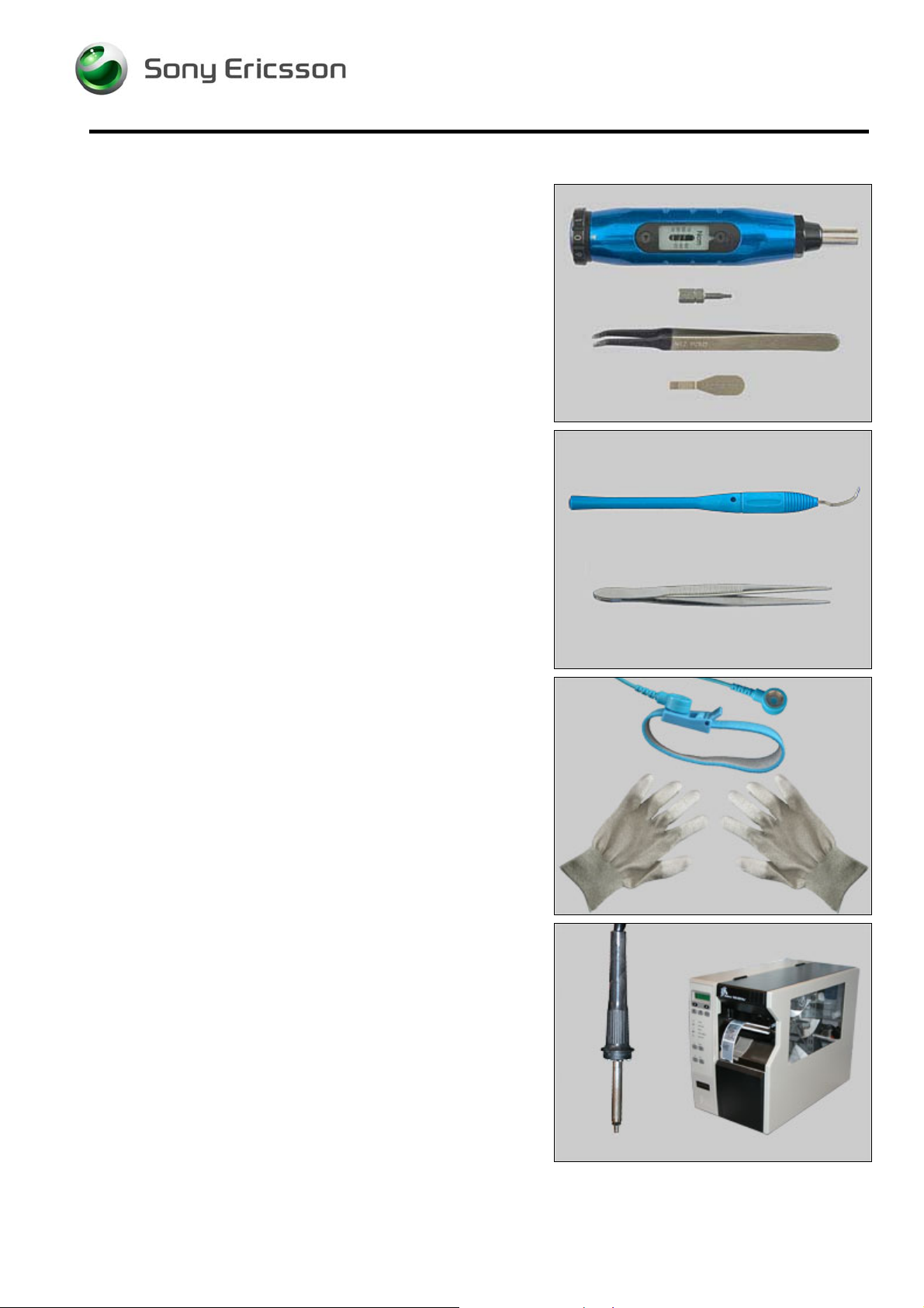
SPECIAL TOOLS
Special tools text:
• NTZ 122 459 Torque screwdriver (or equivalent)
• NTZ 122 288 Torx Bits T6
• NTZ 122 521 Flex film assembly tool
• NTZ 112 302/2 Front opening tool
Working Instruction, Mechanical
STANDARD TOOLS
Standard tools text:
• Dentist hook
• Tweezers
ESD EQUIPMENT
Protect the phone from ESD damages whenever it has
been opened by using:
• ESD-wristband
• ESD-gloves
LABEL EQUIPMENT
The following special equipment is required when replacing
or installing a new label:
• Hot air flow solder station
• Zebra printer connected to computer
1217-1812 1
Company Internal © Sony Ericsson Mobile Communications AB
3(28)

Working Instruction, Mechanical
1.2 General cautions
The following cautions are considered to be generic for all phone models and will not be repeated in
the Disassembly, Replacements and Reassembly sections:
• S
WITCH OFF THE PHONE AND REMOVE ANY MEMORY STICK BEFORE THE START OF THE DISASSEMBLY!
• KEEP ALL CONTACT SURFACES CLEAN!
• BE CAREFUL WHEN USING TOOLS LIKE THE DENTIST HOOK, TWEEZERS, OPENING TOOLS, GUITAR PICK
ETC. TO AVOID SCRATCHES OR DAMAGES TO THE EXTERIOR AND INTERIOR PARTS OF THE PHONE!
E CAREFUL NOT TO DAMAGE ANY CONTACT SPRINGS!
• B
• REMEMBER TO REMOVE THE PROTECTION FOILS ON NEW PARTS SUCH AS THE FRONT COVER AND LCD!
• NEVER TOUCH THE DISPLAY GLASS!
SE AIR BLOW EQUIPMENT TO KEEP THE FRONT WINDOW AND DISPLAY MODULE DUST FREE!
• U
1.3 Adhesives
Use a dentist hook and/or the tweezers to remove old adhesives.
Clean the surface with isopropyl alcohol before attaching new adhesives.
1217-1812 1
Company Internal © Sony Ericsson Mobile Communications AB
4(28)
Working Instruction, Mechanical
2 Disassembly
When you are going to replace a part being listed in Replacements, the instruction of that section
usually begins by directing you to this Disassembly section with a specification of the instructions you
have to carry out in order to disassemble the phone as far as needed before returning to
Replacements for the actual replacement.
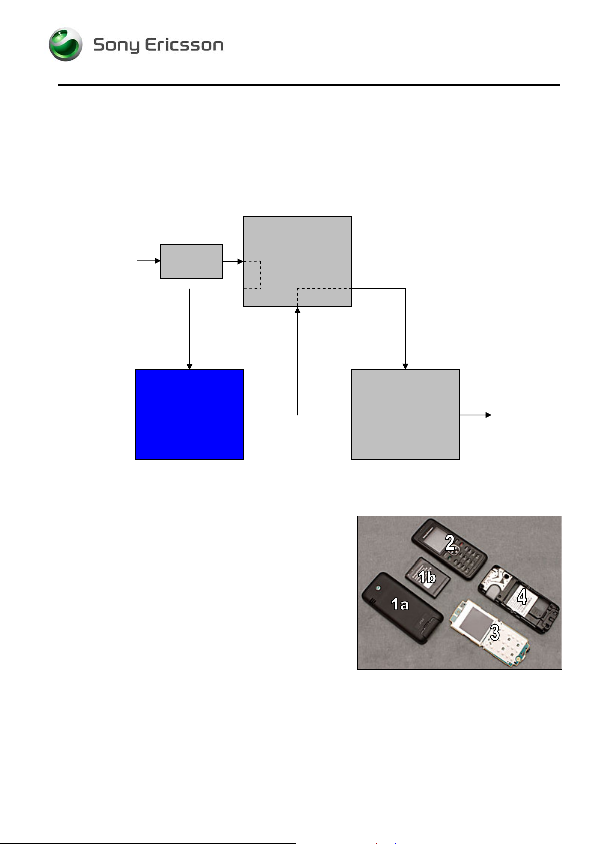
REPLACEMENTS
Start
DISASSEMBLY
2.1 Overview
Contents
page
REASSEMBLY
Done
The disassembly is done in the following sequence:
1. Battery Cover (a) & Battery (b)
2. Front Cover Assembly
3. PCBA
4. Back Cover Assembly
1217-1812 1
Company Internal © Sony Ericsson Mobile Communications AB
5(28)
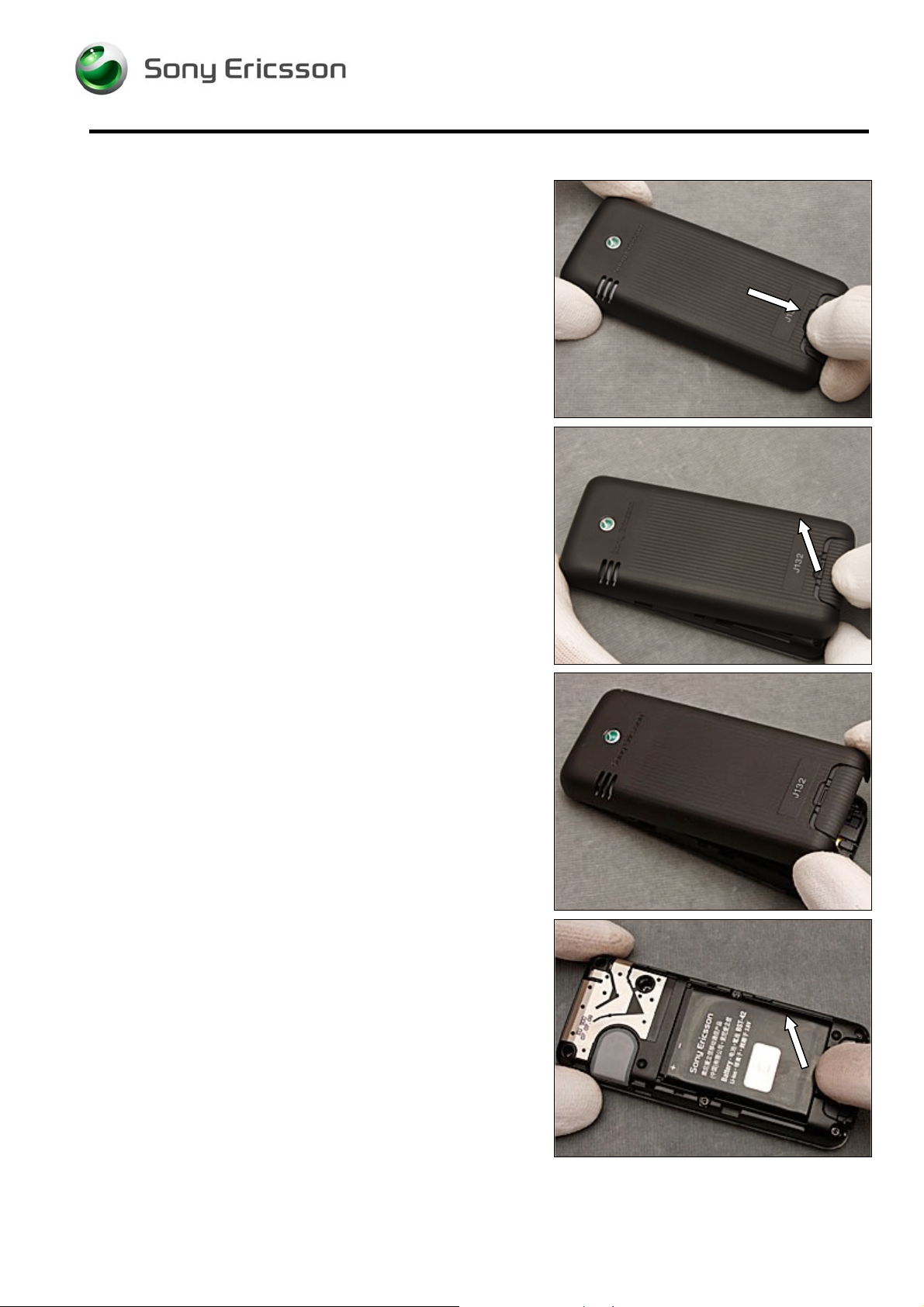
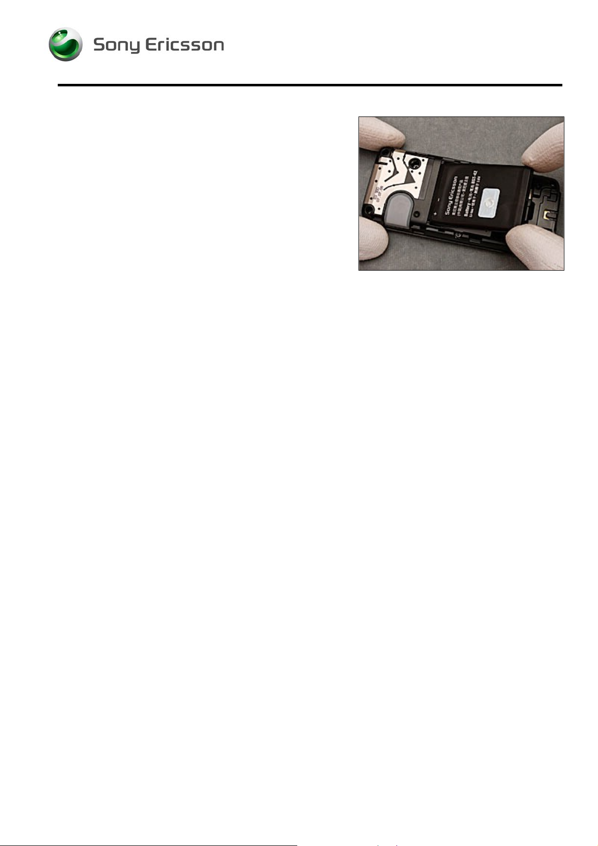
2.1.1 Battery Cover & Battery
Release the lock button as the arrow direction…
Working Instruction, Mechanical
Separate the Battery Cover from the phone as the arrow
direction…
Remove the Battery Cover
Use your fingers to lift up the Battery as the arrow
direction…
1217-1812 1
Company Internal © Sony Ericsson Mobile Communications AB
6(28)
Disassembly Instruction continued
Remove the Battery
Working Instruction, Mechanical
1217-1812 1
Company Internal © Sony Ericsson Mobile Communications AB
7(28)
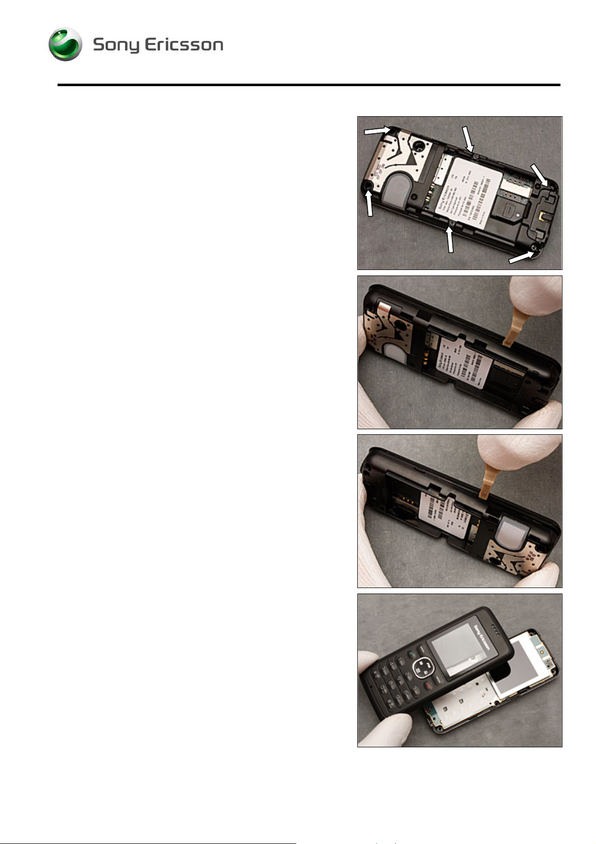
2.1.2 Front Cover Assembly
Use a Torx Bits T6 to remove the six screws
Working Instruction, Mechanical
Use a Front Opening Tool to unsnap the hooks of the Front
Cover Assembly
Continue on the other side to unsnap the hooks of the Front
Cover Assembly
Remove the Front Cover Assembly
1217-1812 1
Company Internal © Sony Ericsson Mobile Communications AB
8(28)
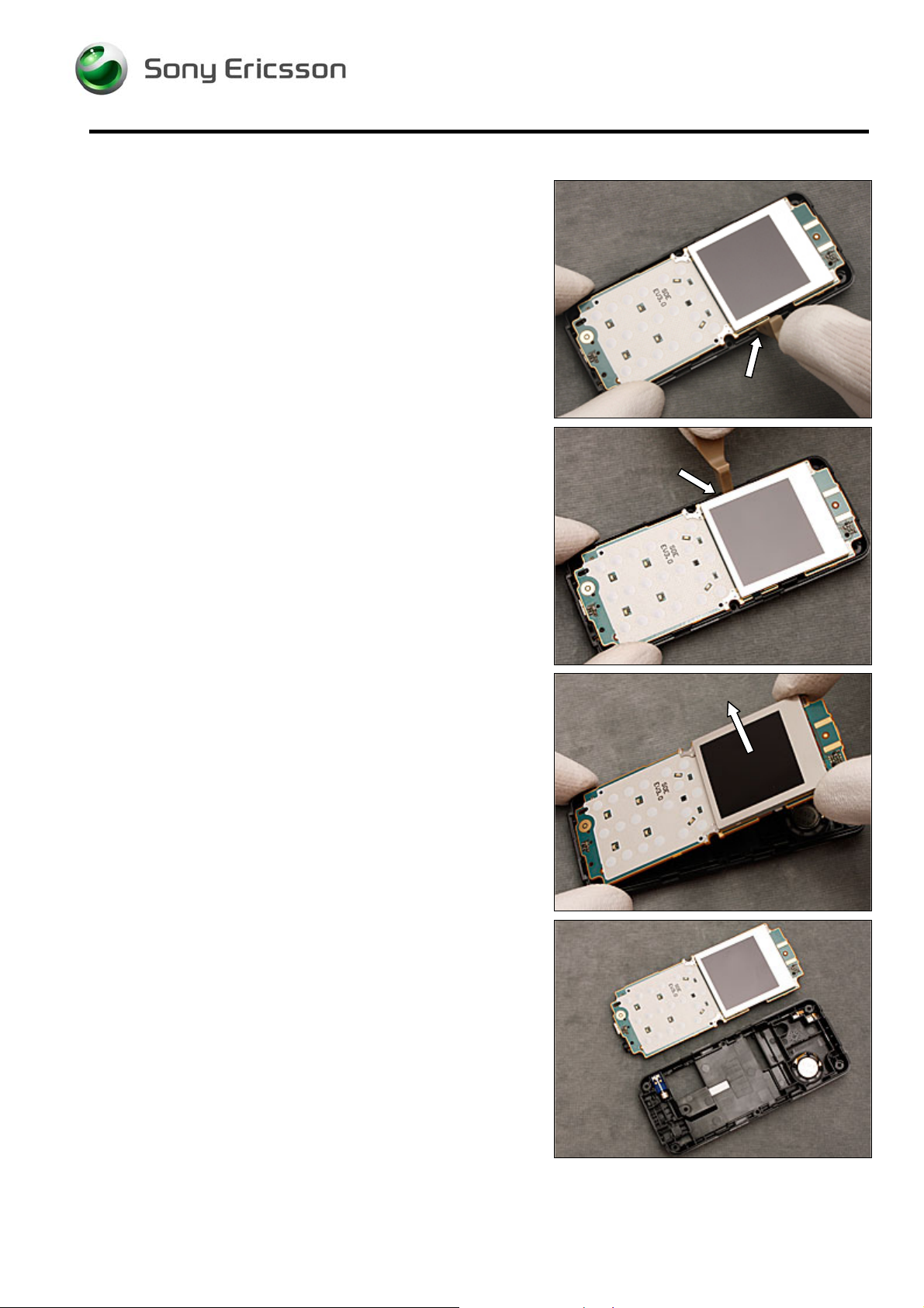
2.1.3 PCBA & Back Cover Assembly
Use a Front Opening Tool to unsnap the PCBA
Working Instruction, Mechanical
Continue on the other side to unsnap the PCBA
Remove the PCBA as the arrow direction…
Separate the PCBA from the Back Cover Assembly
1217-1812 1
Company Internal © Sony Ericsson Mobile Communications AB
9(28)
 Loading...