

Sony XR-C7350X Service manual

XR-C7350X
SERVICE MANUAL
SPECIFICATIONS
US Model
Model Name Using Similar Mechanism XR-C5100
T ape Transport Mechanism T ype MG-25F-136
FM/AM CASSETTE CAR STEREO
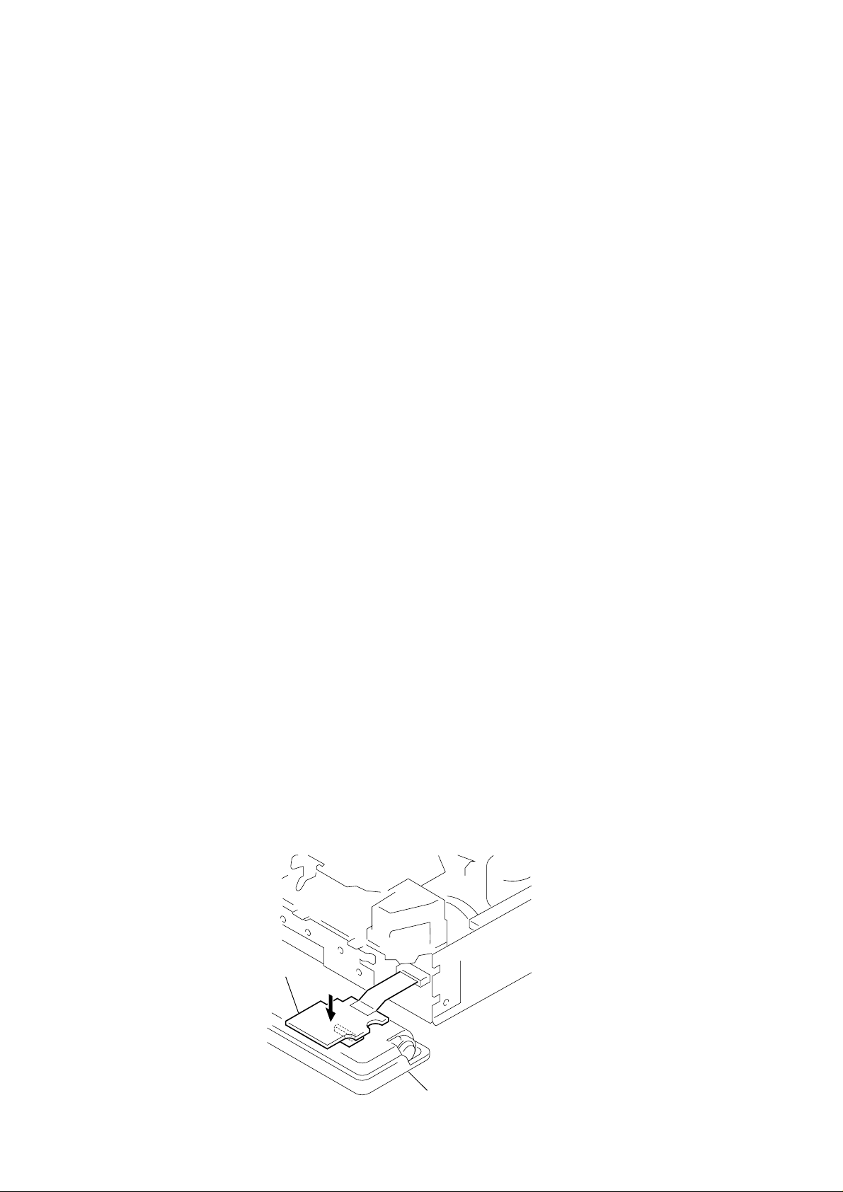
TABLE OF CONTENTS
1. SERVICE NOTE ............................................................. 2
2. GENERAL ........................................................................ 3
3. DISASSEMBLY .............................................................. 8
Flexible Circuit Board Repairing
• Keep the temperature of the soldering iron around 270 ˚C during repairing.
• Do not touch the soldering iron on the same conductor of the
circuit board (within 3 times).
• Be careful not to apply force on the conductor when soldering
or unsoldering.
4. ASSEMBLY OF MECHANISM DECK................ 9
5. MECHANICAL ADJUSTMENTS ............................ 12
6. ELECTRICAL ADJUSTMENTS
6-1. Test Mode........................................................................ 12
• Tape Deck Section ........................................................ 12
• Tuner Section ................................................................ 12
7. DIAGRAMS
7-1. Block Diagrams
• TUNER/TAPE/MAIN Section..................................... 13
• DISPLAY/KEY CONTROL/BUS CONTROL/
POWER SUPPLY Section ........................................... 14
7-2. Schematic Diagram – PRE OUT Board – ...................... 15
7-3. Printed Wiring Board – PRE OUT Board – .................. 15
7-4. Printed Wiring Board – MAIN Board – ......................... 16
7-5. Schematic Diagram – MAIN Board (1/2) – ................... 17
7-6. Schematic Diagram – MAIN Board (2/2) – ................... 18
7-7. Printed Wiring Boards – KEY/SUB Boards – .............. 19
7-8. Schematic Diagrams – KEY/SUB Boards – .................. 20
7-9. IC Block Diagrams ......................................................... 21
7-10. IC Pin Function ............................................................... 22
8. EXPLODED VIEWS................................................ 25
Notes on chip component replacement
• Never reuse a disconnected chip component.
• Notice that the minus side of a tantalum capacitor may be damaged by heat.
9. ELECTRICAL PARTS LIST ............................... 28
SECTION 1
SERVICE NOTE
Please press on the sub board from above when checking it.
This assures that the connector does not lose contact.
SUB board
Front panel assembly
2
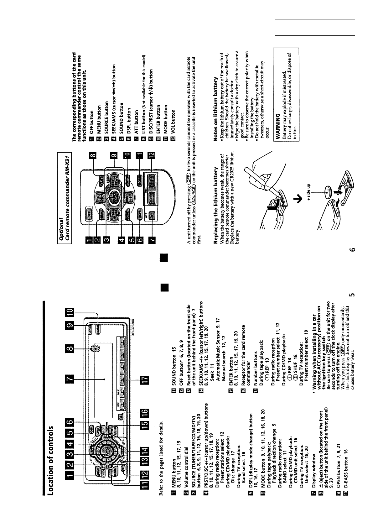
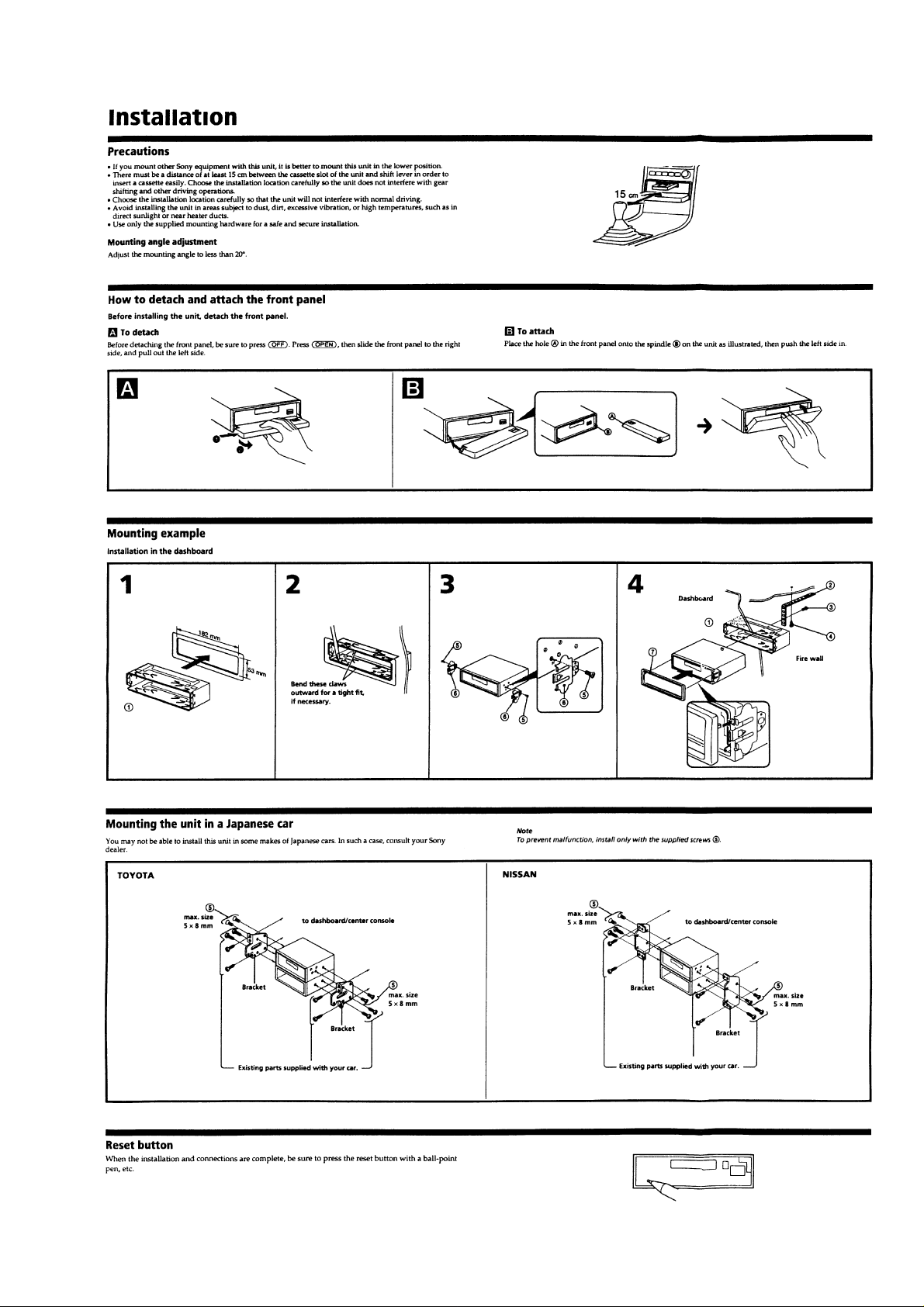
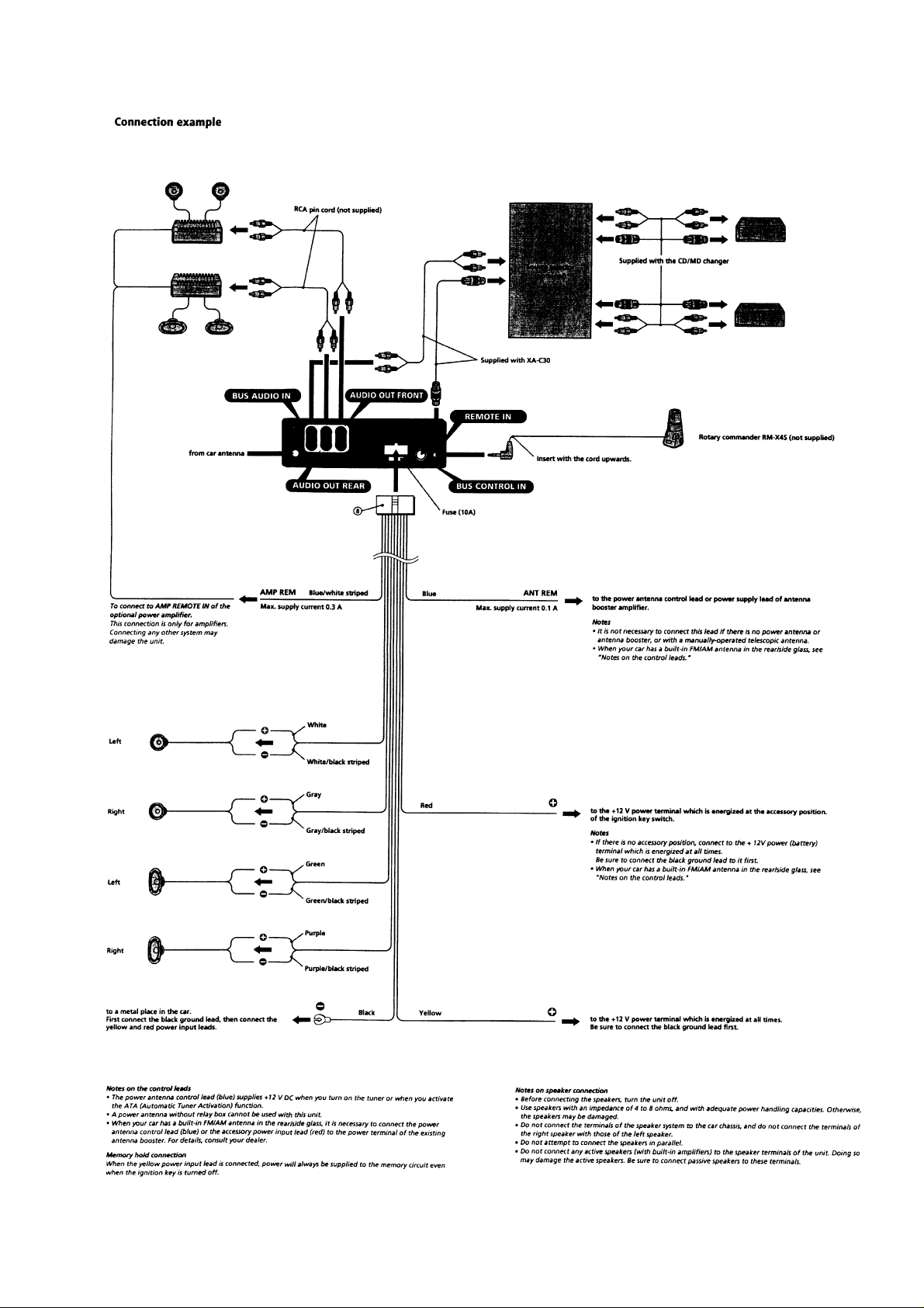
SECTION 2
GENERAL
This section is extracted from
instruction manual.
3

456

7

SECTION 3
DISASSEMBLY
Note: Follow the disassembly procedure in the numerical order given.
SUB PANEL, MECHANISM DECK (MG-25F-136)
0 Mechanism deck
(MG-25F-136)
8 Connector(CN351)
5 Sub panel ass'y
3 Screw
(PTT2.6 × 6)
9 Screw
(PTT2.6 × 6)
7 Flexible flat cable
(CNP301)
2 T wo screws
(PTT2.6 × 6)
MAIN BOARD, HEAT SINK
7 Two ground screws
8 Main board
Sub board
1 T wo screws
(PTT2.6 × 6)
5 Rubber cap(25)
6 Flat cable (WR801)
4 Screw (PTT2.6 × 6)
6 Ground screw
1 Eight screws
(PTT2.6 × 8)
2 T wo screws
(PTT2.6 × 12)
9 Insulated
plate
8
3 Heat sink
4 Ground plate(TU)

SECTION 4
ASSEMBLY OF MECHANISM DECK
Note: Follow the assembly procedure in the numerical order given.
HOUSING
5 Fit projection on C part.
2 Install the hanger onto
two claws of the housing.
4 Fit claw on B part.
7 Holder the hanger by bending the claw.
1 Install the catch to the hanger.
hanger
3 Put the housing
under A part.
ARM (SUCTION)
6 Fit projection on D part.
housing
C part
8 Hold the hanger by
bending the claw.
D part
A part
B part
projection
2 Move the arm (suction) in the arrow
direction and fit on projection.
1 Fit the arm (suction) on the shaft.
9
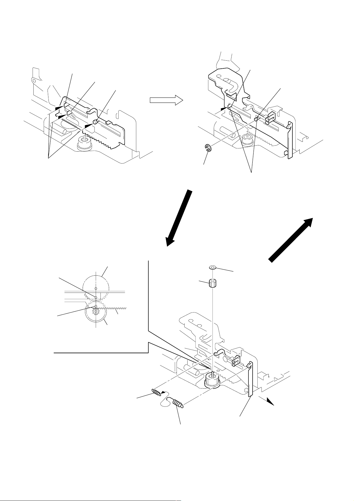
LEVER (LDG-A)/(LDG-B)
shaft A
shaft B
1 Fit the lever (LDG-A) on
shafts A – C and install it.
shaft C
shaft A
shaft B
3 type-E stop ring 2.0
2 Fit the lever (LDG-B) on
shafts A and B and
install it.
GEAR (LDG-FT)
hole
hole
gear (LDG-D)
lever (LDG-A)
gear (LDG-FB)
4 Align hole in the gear (LDG-D)
with hole the lever (LDG-A).
2 tension spring (LD-2)
5 gear (LDG-FT)
1
2 tension spring (LD-1)
6 polyethylene washer
3 Move the lever (LDG-B)
in the arrow direction.
10
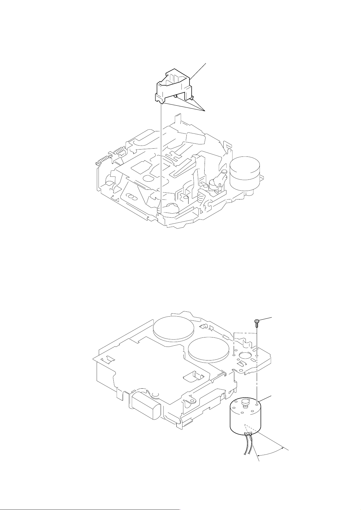
GUIDE (C)
2 guide (C)
1 three claws
MOUNTING POSITION OF CAPSTAN/REEL MOTOR (M901)
two precision screws
(P2
×
2)
capstan/reel motor
(M901)
30˚
11
 Loading...