

Sony XM-404EQX Owner’s Manual

Stereo Power
Amplifier
Operating Instructions
Mode d'emploi
Owner's Record
The model and serialnumbers arelocatedon thebottom of theunit.
Record theserialnumber inthespaceprovided below.
Refertothesenumbers whenever you callupon your Sony dealerregardingthisproduct.
Model No. XM-404EQX SerialNo.
XM-404EQX
Sony Corporation @1999

2
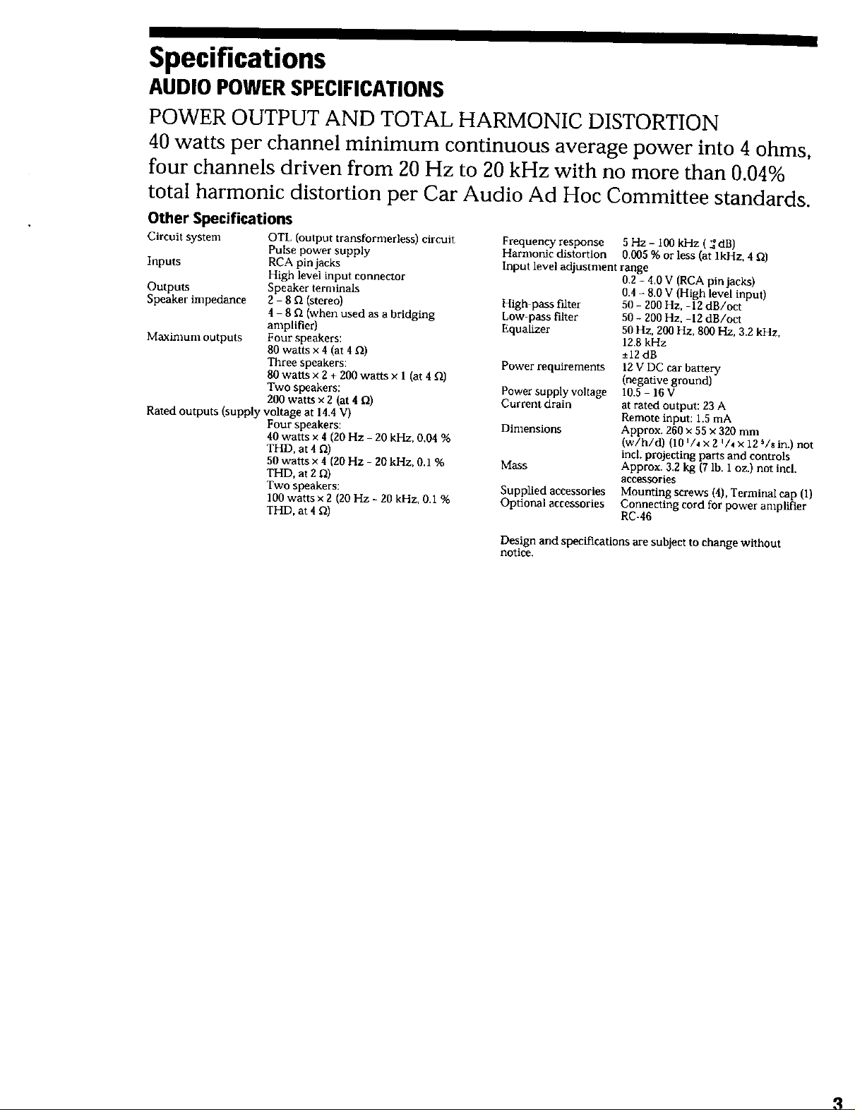
Specifications
AUDIO POWER SPECIFICATIONS
POWER OUTPUT AND TOTAL HARMONIC DISTORTION
40 watts per channel minimum continuous average power into 4 ohms,
four channels driven from 20 Hz to 20 kHz with no more than 0.04%
total harmonic distortion per Car Audio Ad Hoc Committee standards.
Other Specifications
Circuit system OTL (output transformerless) circuit
Pulse power supply
Inputs RCA pin jacks
High level input connector
Outputs Speaker terminals
Speaker impedance 2 - 8 _ (stereo)
4 - 8 _ (when used as a bridging
amplifier)
Maximum outputs Four speakers:
80 watts x 4 (at 4 _)
Three speakers:
80 watts x 2 + 200 watts x I (at 4 _)
Two speakers:
200 watts x 2 (at 4 Q)
Rated Outputs (supply voltage at 14,4 V)
Four speakers:
40 watts x 4 (20 Hz 20 kHz, 0.04 %
THD, at 4 f2)
50 watts x 4 (20 Hz - 20 kHz, 0.1%
THD, at 2 _0
Two speakers:
100 watts x 2 (20 Hz - 20 kHz, 0.1%
THD, at 4 fl)
Frequency response 5 Hz - i00 kHz ( _ dB)
Harmonic distortion 0.005 % or less (at lkHz, 4 fl)
Input level adjustment range
High pass filter 50 - 200 Hz, -12 dB/oct
Low-pass filter 50 - 200 Hz. -12 dB/oct
Equalizer 50 Hz, 200 Hz, 800 Hz, 3.2 kHz,
Power requirements
Power supply voltage
Current drain
Dimensions
Mass Approx. 3.2 kg (7 lb. 1 oz.) not incl.
Supplied accessories Mounting screws (4), Terminal cap (1)
Optional accessories Connecting cord for power ampliPmr
0.2 - 4.0 V (RCA pin jacks)
0.4 - 8.0 V (High level input)
12.8 kHz
-+12dg
lg V DC car battery
(negative ground)
10.5 - 16 V
at rated output: 23 A
Remote input: 1.5 mA
Approx. 260 × 55 x 320 mm
(w/h/d) (10 i/, x Z i/, x 125/8 in.) not
incl. projecting parts and controls
accessories
RC-46
Design and specifications are subject to change without
notice.
R
Features
•Maximum power output of 80 watts per channel (at
4ohms).
• This unit can be used as a bridging amplifier with a
maximum output of 200 watts.
• Direct connections can be made with the speaker
outputs of your car audio if it is not equipped with
the line output (High level input connection).
• Low-pass filter, high-pass filter, and five band
equalizer circuit are built-in.
• The DIRECT switch can be used to bypass the low
Pulse power supply
This unit has a built-in power regulator which converts the
power supplied by the DC 12 V car battery into high speed
pubes using a semtconductor switch. These pulses are
stepped up by the built-in pulse transformer and separated
into both positive and negative power supplies before being
converted into direct current again. This is to regulate
fluctuating voltage from the car battery. This light weight
power supply system provides a highly efflclent power supply
with a low impedance output.
pass filter, high-pass filter, and equalizer circuit for
more enjoyable high quality sound.
• You can visually confirm the output level of both the
left and right sides with the power level indicator.
• Protection circuit and indicator provided.
• Pulse power supply* for stable, regulated output
power.
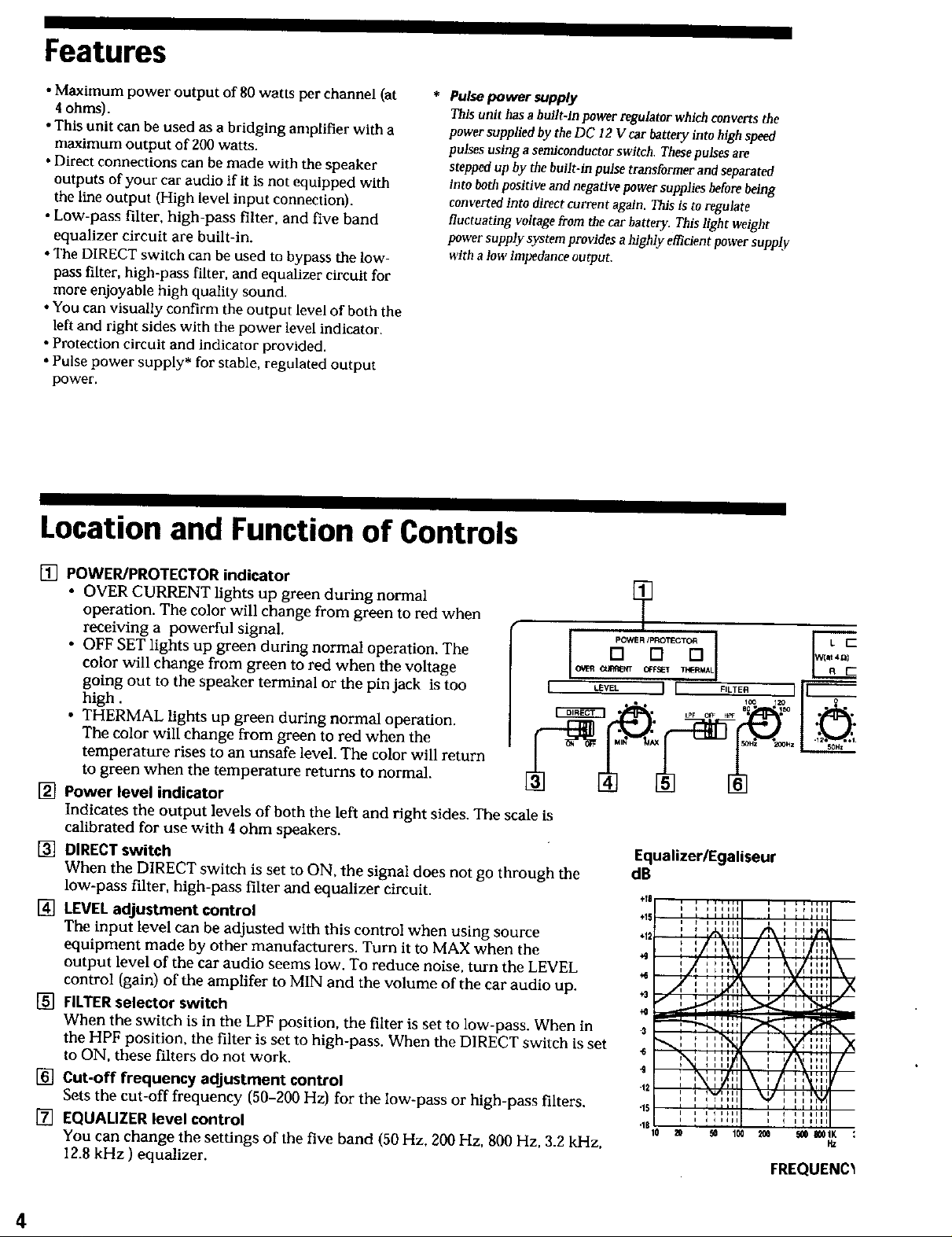
Location and Function of Controls
[] POWER/PROTECTOR indicator
• OVER CURRENT lights up green during normal
operation. The color will change from green to red when
receiving a powerful signal.
• OFF SET lights up green during normal operation. The
color will change from green to red when the voltage
going out to the speaker terminal or the pin jack is too
high.
• THERMAL lights up green during normal operation.
The color will change from green to red when the
temperature rises to an unsafe level. The color will return
to green when the temperature returns to normal.
[] Power level indicator
Indicates the output levels of both the left and right sides. The scale is
calibrated for use with 4 ohm speakers.
[] DIRECT switch
When the DIRECT switch is set to ON, the signal does not go through the
low-pass filter, high-pass filter and equalizer circuit.
[] LEVEL adjustment control
The input level can be adjusted with this control when using source
equipment made by other manufacturers. Turn it to MAX when the
output level of the car audio seems low. To reduce noise, turn the LEVEL
control (gain) of the amplifer to MIN! and the volume of the car audio up.
[] FILTERselector switch
When the switch is in the LPF position, the filter is set to low-pass. When in
the HPF position, the filter is set to high-pass. When the DIRECT switch is set
to ON, these filters do not work.
[] Cut-off frequency adjustment control
Sets the cut-off frequency (50-200 Hz) for the low-pass or high-pass filters.
[] EQUALIZER level control
You can change the settings of the five band (50 Hz, 200 Hz, 800 Hz, 3.2 kHz,
12.8 kHz ) equalizer.
O_R O3RREk'T OPPS_ ThFRMAL
I LEVEL I [ FILTE._.--._R ] [[
EquatizerlEgaliseur
dB
÷18
i , llIHI I , * _lr,,
€15 ' , ,ll,il r Jill
.12 .....
l,,MIII I_
i ','1'"
ill i i ;lii
÷3
.6 N .... ] i _,'_ .... /
-9
"12 I I tt i ill
q5 , i i liHi i i ii
"11
'N:7' \ i/] "
i t i _11 i i
' ': ..... I I ......
i i i i Iii i i 1111
10 20 ' _ 100 _0 _ _IK :
w
FREQUENC_
Itz
4
[] Cut-off frequency adjustment control
Sets the cut-off frequency (50-200 Hz) for the low-pass or high-pass filters.
[] EQUALIZER level control
You can change the setUngs of the five band (50 Hz, 200 Hz. 800 Hz. 3.2 kHz,
12.8 kHz ) equalizer.
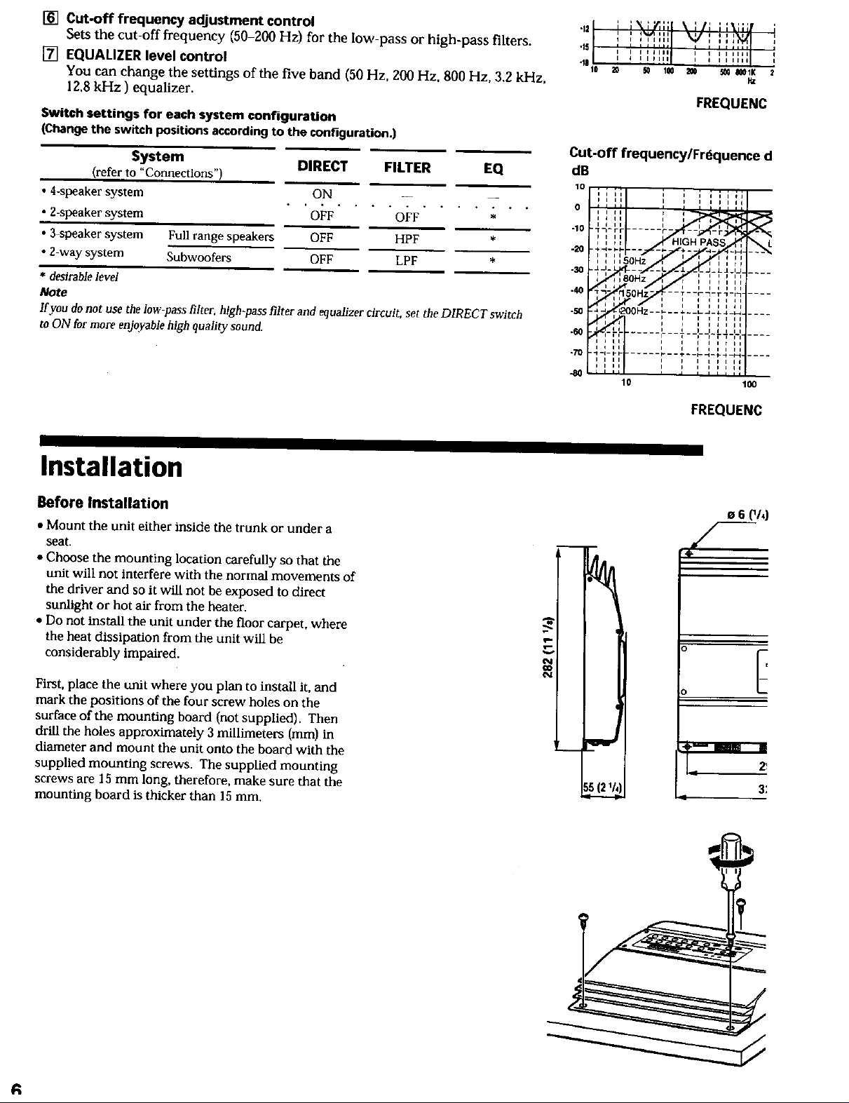
Switch settings for each system configuration
(Change the switch positions according to the cont-_juration.)
System
(referto "Connections")
• 4-speaker system
• Z-speaker system
• 3 speaker system
• 2 way system
* desirable level
Note
If you do not use the low-pass filter, fiigh-pass filter and equalizer circuit, set the DIRECT switch
to ON for more enjoyable high quality sound.
Full range speakers
Subwoofers
w _ m
DIRECT FILTER EQ
ON -- _
• 'O F.... O 'F.... ; " "
OFF HPF
OFF LPF *
._21 ; ;_L;r,;;I \i/i ;:_;;;I '
t ....... I ....
i i ill,i, * , , *lilt I
10 20 _ 100 _0 _0 I_IK 2
FREQUENC
Cut-off frequencylFrdquence d
dB
10
i i i i i i i i i _J
o III ' ' ' '''"i i i i i i J
i I i i
-10 "1-l-r r ...... r-
i I _ I i I
.20 .4-4-_-_- -- ._.H.
i _ ii _- i ( i i
, , ,,50Hz i , , r,
._j .A J- --. -J- LA_tJ .....
_ I 8OH, r _ I r t t I
-40 0 ....
-so -.'_'_._,_o_z --L - - I - _L"- L"-.''.....
4_0 _rF_ ...... i.--T----r_r_÷-i .....
,_ I I I I I I i I I i I
I I I I i _ i II
i_g|_i I _ I I J I I I I I
i k i i I i I i f I
i _ t i i i i i i _
i i } i I } i I
FREQUENC
Installation
Before Installation
• Mount the unit either inside the trunk or under a
seat.
• Choose the mounting location carefully so that the
unit will not interfere with the normal movements of
the driver and so it will not be exposed to direct
sunlight or hot air from the heater.
• Do not install the unit under the floor carpet, where
the heat dissipation from the unit will be
considerably impaired.
First, place the unit where you plan to install it, and
mark the positions of the four screw holes on the
surface of the mounting board (not supplied). Then
drill the holes approximately 3 millimeters (mm) in
diameter and mount the unit onto the board with the
supplied mounting screws. The supplied mounting
screws are 15 mm long, therefore, make sure that the
mounting board is thicker than 15 ram.
e 6 (_/4)
E
3;
R
 Loading...