

Sony X-JS7 Service Manual
CD PLAYER
Laser Semiconductor laser
(λ = 780 nm)
Emission duration:
continuous
D/A converter 1 bit dual
Signal-to-noise ratio 85 dB (1 kHz, 0 dB)
Harmonic distortion 0.05 % (1 kHz, 0 dB)
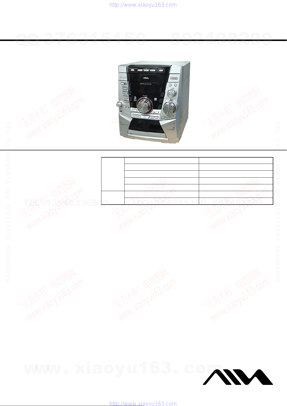
CX-JS7
Q
Q
3
7
6
3
1
5
1
5
0
SERVICE MANUAL
Ver. 1.2 2005.05
TEL 13942296513 QQ 376315150 892498299
CX-JS7 is the tuner, amplifier , cassette dec k and
CD player section in JAX-S7.
Model Name Using Similar Mechanism NEW
CD Mechanism Type CDM74F-K6BD71A
Base Unit Name BU-K6BD71A
Optical Block Name KSM-213DCP
Optical Pick-up Name KSS-213D
Model Name Using Similar Mechanism NEW
Tape Transport Mechanism Type CWM43FF13
Q
Q
3
7
TEL
CD
Section
Tape deck
Section
13942296513
8
6
3
9
1
5
2
1
5
4
0
9
8
9
2
8
US Model
8
9
4
2
9
2
9
9
TEL 13942296513 QQ 376315150 892498299
9
TUNER
FM tuning range 87.5 MHz to 108 MHz
FM usable sensitivity (IHF) 13.2 dBf
FM antenna terminal 75 ohms (unbalanced)
AM tuning range 530 kHz to 1710 kHz (10 kHz step)
531 kHz to 1710 kHz (9 kHz step)
AM usable sensitivity 350 µV/m
AM antenna Loop antenna
AMPLIFIER
Power output 160 W + 160 W (40 Hz - 20 kHz,
THD less than 1 %, 6 ohms)
200 W + 200 W (1 kHz, THD less
than 10 %, 6 ohms)
Total harmonic distortion 0.08 % (100 W, 1 kHz, 6 ohms)
Input VIDEO (MD): 500 mV
Outputs SPEAKERS: 6 ohms or more
PHONES: 32 ohms or more
CASSETTE DECK
Track format 4 tracks, 2 channels stereo
Frequency response 50 Hz – 8 kHz
Recording system AC bias
Heads Deck A: playback x 1
Deck B: recording/playback x 1,
erase x 1
SPECIFICATIONS
GENERAL
Power requirements 120 V AC, 60 Hz
Power consumption 160 W
Power consumption With ECO mode on: 0.25 W
in standby mode With ECO mode off: 25 W
Dimensions (W x H x D) 280 x 328 x 437 mm
Weight 10.2 kg (22 lbs 8 oz)
Specifications and external appearance are subject to change
without notice.
1
(11
/8 x 12 15/16 x 17 7/32 in.)
COMPACT DISC DECK RECEIVER
COPYRIGHT
Check copyright laws relevant to recordings from discs, tuner
or tape for the country where the unit is to be used.
Licensed by BBE Sound, Inc. under USP4638258, 5510752
and 5736897.
w
w
w
9-877-265-03 Sony Corporation
2005E05-1 Personal Audio Group
© 2005.05 Published by Sony Engineering Corporation
.
xia
o
y
u
1
6
3
.
c
o
m
CX-JS7
r
Notes on chip component replacement
•Never reuse a disconnected chip component.
Q
Q
• Notice that the minus side of a tantalum capacitor may be damaged by heat.
Flexible Circuit Board Repairing
•Keep the temperature of the soldering iron around 270 ˚C during repairing.
• Do not touch the soldering iron on the same conductor of the
circuit board (within 3 times).
• Be careful not to apply force on the conductor when soldering
or unsoldering.
SAFETY CHECK-OUT
After correcting the original service problem, perform the following safety check before releasing the set to the customer:
Check the antenna terminals, metal trim, “metallized” knobs, screws,
TEL 13942296513 QQ 376315150 892498299
and all other exposed metal parts for AC leakage.
Check leakage as described below.
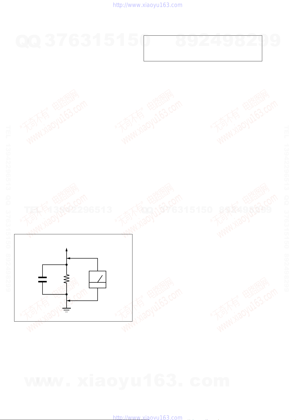
LEAKAGE TEST
The AC leakage from any exposed metal part to earth ground and
from all exposed metal parts to any exposed metal part having a
return to chassis, must not exceed 0.5 mA (500 microamperes.).
Leakage current can be measured by any one of three methods.
1. A commercial leakage tester, such as the Simpson 229 or RCA
WT-540A. Follow the manufacturers’ instructions to use these
instruments.
2. A battery-operated AC milliammeter. The Data Precision 245
digital multimeter is suitable for this job.
3. Measuring the voltage drop across a resistor by means of a V OM
or battery-operated A C voltmeter . The “limit” indication is 0.75
V, so analog meters must have an accurate low-voltage scale.
TEL
The Simpson 250 and Sanwa SH-63Trd are examples of a passive VOM that is suitable. Nearly all battery operated digital
multimeters that have a 2 V AC range are suitable. (See Fig. A)
7
3
13942296513
6
3
1
5
1
5
CAUTION
0
Use of controls or adjustments or performance of procedures
other than those specified herein may result in hazardous radiation exposure.
7
3
Q
Q
8
6
3
9
1
5
2
1
5
4
0
9
8
9
8
2
4
2
9
8
9
2
9
9
TEL 13942296513 QQ 376315150 892498299
9
To Exposed Metal
Parts on Set
AC
o
voltmete
(0.75 V)
y
1.5 k
Earth Ground
.
xia
Ω
0.15 µF
Fig. A. Using an AC voltmeter to check AC leakage.
SAFETY-RELATED COMPONENT WARNING!!
COMPONENTS IDENTIFIED BY MARK 0 OR DOTTED
LINE WITH MARK 0 ON THE SCHEMATIC DIAGRAMS
AND IN THE PARTS LIST ARE CRITICAL TO SAFE
OPERATION. REPLACE THESE COMPONENTS WITH
w
w
SONY PARTS WHOSE PART NUMBERS APPEAR AS
SHOWN IN THIS MANUAL OR IN SUPPLEMENTS PUBLISHED BY SONY.
w
u
1
6
3
.
c
o
m
2

TABLE OF CONTENTS
7
Q
Q
TEL 13942296513 QQ 376315150 892498299
3
1. SERVICING NOTES ................................................ 4
2. GENERAL
Location of Controls ....................................................... 7
3. DISASSEMBLY
3-1. Disassembly Flow ........................................................... 9
3-2. Case (SIDE-L/R) ............................................................. 10
3-3. Case (Top) ....................................................................... 10
3-4. Tray Panel........................................................................ 11
3-5. CD Mechanism Deck (CDM74F-K6BD71A) ................ 11
3-6. Fr ont Panel Section ......................................................... 12
3-7. Mechanical Deck............................................................. 12
3-8. Rear Cabinet Section ...................................................... 13
3-9. Main Board ...................................................................... 13
3-10. Power Board .................................................................... 14
3-11. Transformer Board .......................................................... 14
3-12 Table Assy ....................................................................... 15
3-13. Motor (TB) Board ........................................................... 15
3-14. Motor (LD) Board ........................................................... 16
3-15. Base Unit (BU-K6BD71A)............................................. 16
3-16. Motor Gear Assy (Sled) (M701), BD Board .................. 17
3-17. Optical Pick-up (KSS-213D) .......................................... 17
6
3
1
5
1
5
0
7. EXPLODED VIEWS
7-1. Case Section .................................................................... 53
7-2. F ront Panel Section-1 ...................................................... 54
7-3. F ront Panel Section-2 ...................................................... 55
7-4. F ront Panel Section-3 ...................................................... 56
7-5. F ront Panel Section-4 ...................................................... 57
7-6. Chassis Section-1 ............................................................ 58
7-7. Chassis Section-2 ............................................................ 59
7-8. CD Mechanism Deck Section-1
7-9. CD Mechanism Deck Section-2
7-10. CD Mechanism Deck Section-3
7-11. Base Unit Section (BU-K6BD71A) ............................... 63
8. ELECTRICAL PARTS LIST ............................... 64
CX-JS7
4
2
9
8
(CDM74F-K6BD71A) .................................................... 60
(CDM74F-K6BD71A) .................................................... 61
(CDM74F-K6BD71A) .................................................... 62
9
8
2
9
9
TEL 13942296513 QQ 376315150 892498299
4. TEST MODE.............................................................. 18
5. ELECTRICAL ADJUSTMENTS
CD Section ...................................................................... 21
6. DIAGRAMS
TEL
13942296513
6-1. Block Diagram – CD Section – ..................................... 22
6-2. Block Diagr am – TUNER/TAPE/PANEL Section –..... 23
6-3. Block Diagram – AMP/POWER SUPPLY Section – ... 24
6-4. Note for Printed Wiring Boards and
Schematic Diagrams ....................................................... 25
6-5. Printed Wiring Board – BD Board – ............................. 26
6-6. Schematic Diagram – BD Board – ................................ 27
6-7. Printed Wiring Boards – CHANGER Section – ............ 28
6-8. Schematic Diagram – CHANGER Section – ................ 29
6-9. Schematic Diagram – MAIN Board (1/4) – .................. 30
6-10. Schematic Diagram – MAIN Board (2/4) – .................. 31
6-11. Schematic Diagram – MAIN Board (3/4) – .................. 32
6-12. Schematic Diagram – MAIN Board (4/4) – .................. 33
6-13. Printed Wiring Board – MAIN Board – ........................ 34
6-14. Printed Wiring Board – Power Board – ......................... 35
6-15. Schematic Diagram – Power Board (1/2) –................... 36
6-16. Schematic Diagram – Power Board (2/2) –................... 37
6-17. Printed Wiring Boards
– CD BUTTON/HEADPHONE Boards –...................... 38
6-18. Schematic Diagram
– CD BUTTON/HEADPHONE Boards –...................... 39
6-19. Printed Wiring Board – PANEL Board – ...................... 40
6-20. Schematic Diagram – PANEL Board – ......................... 41
6-21. Printed Wiring Board – TRANSFORMER Board – ..... 42
6-22. Schematic Diagram – TRANSFORMER Board – ........ 43
6-23. IC Pin Function Description ........................................... 47
Q
Q
3
7
6
3
1
5
1
5
0
8
9
2
4
9
8
2
9
9
w
w
w
.
xia
o
y
u
1
6
3
.
c
o
m
3
CX-JS7
SECTION 1
SERVICING NOTES
NOTES ON HANDLING THE OPTICAL PICK-UP
BLOCK OR BASE UNIT
Q
Q
The laser diode in the optical pick-up block may suffer electrostatic break-down because of the potential difference generated
by the charged electrostatic load, etc. on clothing and the human
body.
During repair, pay attention to electrostatic break-down and also
use the procedure in the printed matter which is included in the
repair parts.
The flexible board is easily damaged and should be handled with
care.
NOTES ON LASER DIODE EMISSION CHECK
The laser beam on this model is concentrated so as to be focused
on the disc reflective surface by the objective lens in the optical
TEL 13942296513 QQ 376315150 892498299
pick-up block. Therefore, when checking the laser diode emission, observe from more than 30 cm away from the objectiv e lens.
LASER DIODE AND FOCUS SEARCH OPERATION
CHECK
Carry out the “S curve check” in “CD section adjustment” and
check that the S curve waveforms is output three times.
3
7
6
3
1
5
1
5
0
8
9
2
4
9
8
2
9
9
TEL 13942296513 QQ 376315150 892498299
UNLEADED SOLDER
Boards requiring use of unleaded solder are printed with the leadfree mark (LF) indicating the solder contains no lead.
(Caution: Some printed circuit boards may not come printed with
the lead free mark due to their particular size)
TEL
: LEAD FREE MARK
Unleaded solder has the following characteristics.
• Unleaded solder melts at a temperature about 40 ˚C higher than
ordinary solder.
Ordinary soldering irons can be used but the iron tip has to be
applied to the solder joint for a slightly longer time.
Soldering irons using a temperature regulator should be set to
about 350 ˚C.
Caution: The printed pattern (copper foil) may peel away if the
• Strong viscosity
Unleaded solder is more viscou-s (sticky, less prone to flow)
than ordinary solder so use caution not to let solder bridges occur such as on IC pins, etc.
• Usable with ordinary solder
It is best to use only unleaded solder but unleaded solder may
also be added to ordinary solder.
RELEASING THE DISC TRAY LOCK
The disc tray lock function for the antitheft of an demonstration
disc in the store is equipped.
13942296513
heated tip is applied for too long, so be careful!
Q
Q
3
7
6
3
1
5
1
5
0
8
9
2
4
9
8
2
9
9
Releasing Procedure :
While pressing the
message “UNLOCKED” is displayed and the tray is unlocked.
Note: When “LOCKED” is displayed, the tray lock is not released by
turning power on/off with the [POWER] key.
w
w
4
x key, press the Z key for 5 seconds. The
w
.
xia
o
y
u
1
6
3
.
c
o
m
Q
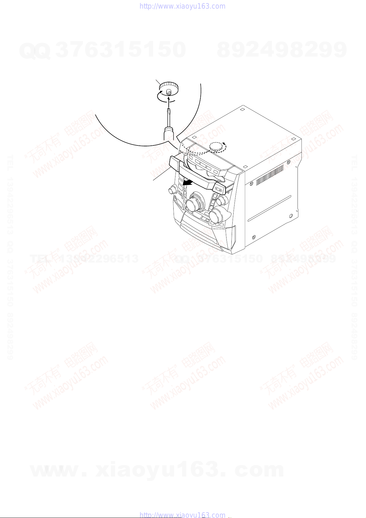
HOW TO OPEN THE DISC TRAY WHEN POWER SWITCH TURNS OFF.
Q
3
7
6
1
2
1
5
3
Remove the case (side-L).
Turn the loading gear
in the direction of arrow A.
1
A
5
0
8
9
2
4
9
8
2
CX-JS7
9
9
TEL 13942296513 QQ 376315150 892498299
3
Pull-out the disc tray.
TEL
13942296513
Q
Q
3
7
6
3
1
5
1
5
0
8
9
2
4
9
8
2
9
TEL 13942296513 QQ 376315150 892498299
9
w
w
w
.
xia
o
y
u
1
6
3
.
c
o
m
5
CX-JS7
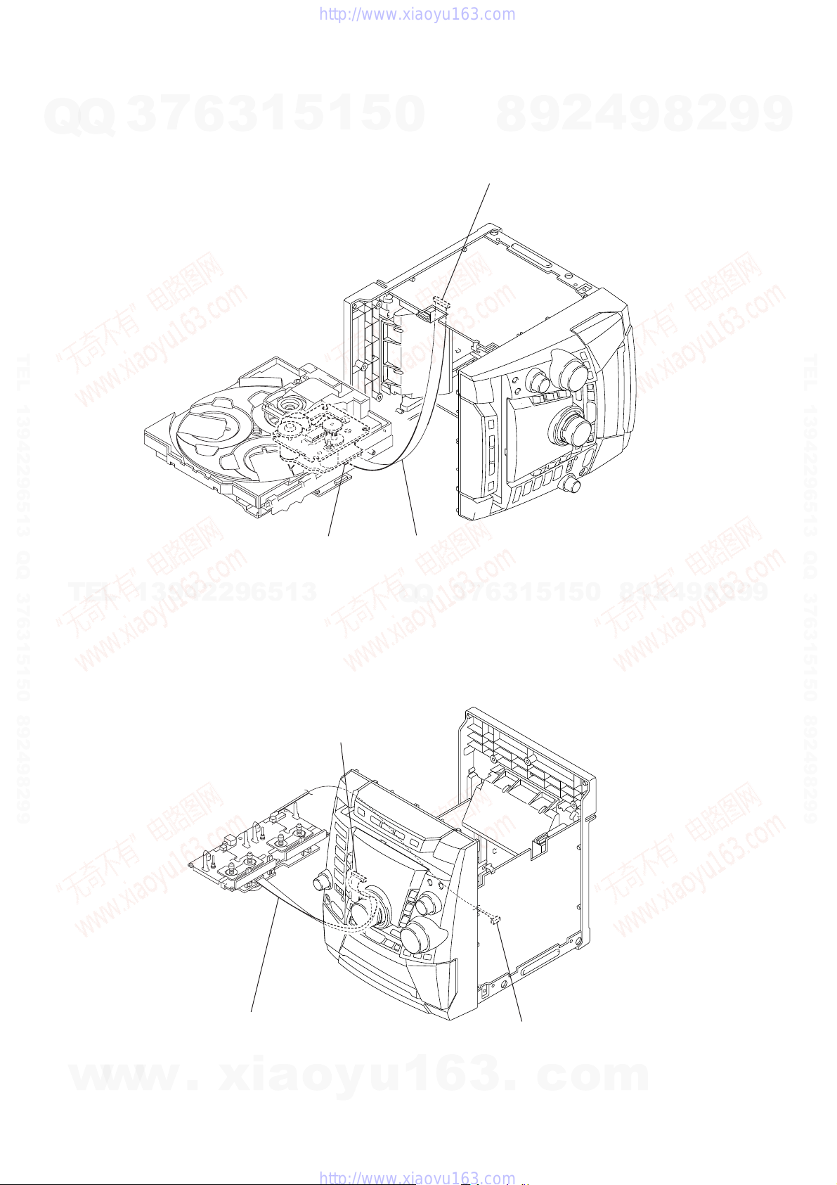
SERVICE POSITION
– CD mechanism deck –
Q
Q
3
7
6
3
1
5
1
5
0
2
9
8
main board (CN312)
4
9
8
2
9
9
TEL 13942296513 QQ 376315150 892498299
TEL
– Tape mechanism deck –
13942296513
BD board (CN710)
panel board (CN601)
Connect wire (flat type) (19 core) to
main board (CN312) and BD board (CN710).
7
3
Q
Q
6
3
1
5
1
5
0
8
9
2
4
9
8
2
9
TEL 13942296513 QQ 376315150 892498299
9
6
w
w
w
Connect wire (flat type) (13 core) to
panel board (CN601) and mechanical deck.
.
xia
o
y
u
1
6
main board (CN203)
3
.
c
o
m
# BASS
Adjusts low frequency sound.
SURROUND
Switches surround on and off.
i-Bass
Produces rich and clear low frequency sound.
$ DISPLAY
Displays the time and the remaining time for CD.
When the unit is off, press DISPLAY to switch between
DEMO, Clock and ECO display modes.
ALBUM k/i
Selects a previous album or a succeeding album with
MP3-CDs.
% r TUNING DOWN, tTUNING UP
(f , g)
CD: searches a track in fast forward or fast reverse
playback when held down.
Tape: fast forwards or rewinds the tape.
Tuner: manually tunes down or up within the band.
aPAUSE
CD and Tapes: pauses playback.
c
CD and Tapes: starts playback.
sSTOP
CD and Tapes: stops playback.
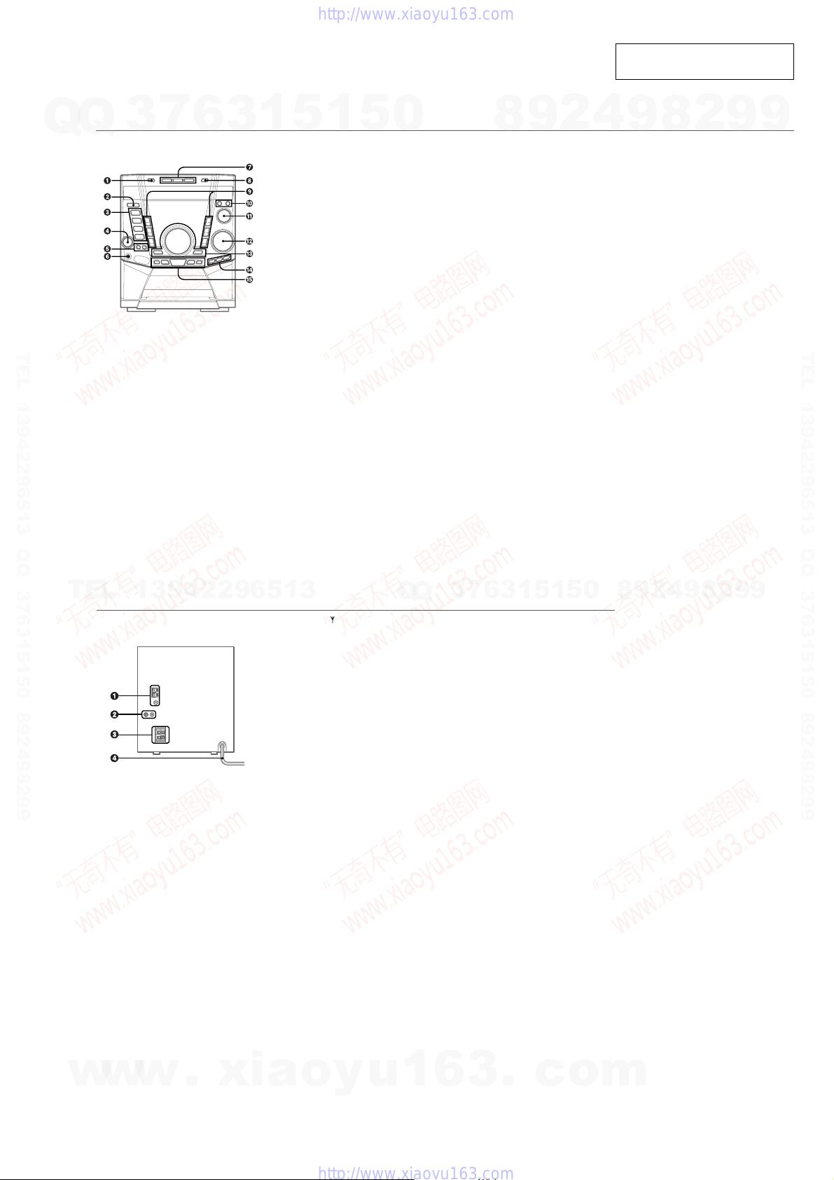
SECTION 2
GENERAL
• LOCATION OF CONTROLS
7
Q
Q
TEL 13942296513 QQ 376315150 892498299
3
Main unit: front
Refer to the pages indicated in parentheses for details.
6
3
1
5
1
1 DISC CHANGE/DISC SKIP
Rotates the CD trays.
2 POWER 6STANDBY/ON
Switches the unit on and off (standby).
The red indicator flashes when receiving a signal from
the remote.
3 TAPE A/B
Selects Tape function, and deck A or B.
TUNER BAND
Selects Tuner function and the radio band.
VIDEO (MD)
Selects the function of external equipment connected to
VIDEO (MD) jacks.
CD
Selects CD function.
4 TREBLE/MIDDLE
Enhances high or middle frequency sound.
5 CD SYNC
Starts Automatic CD dubbing.
REC PAUSE/START
Starts recording.
6 PHONES jack
Plug in here an optional headphones set with a mini
stereo plug (ø3.5 mm). Speaker output is canceled.
5
0
7 DISC DIRECT PLAY 1-3
Selects a disc.
8 zOPEN/CLOSE
Opens or closes the disc compartment.
9 HEAVY, VOCAL, SALSA, TECHNO,
HIP HOP, MANUAL
Activates a graphic equalization curve.
0 MODE
Selects various modes (Play mode, etc.) when used in
combination with ENTER and MULTI JOG.
ENTER
Fixes the modes and the time (Play mode, etc.) when
used in combination with MODE and MULTI JOG.
! MULTI JOG
CD: skips to a previous or a succeeding track.
Tuner: selects a preset station.
Clock and Timer: sets the time.
Selects the mode and the time when used in combination
with MODE and ENTER.
@ VOLUME
Adjusts the volume.
8
9
2
This section is extracted from
instruction manual.
4
9
8
2
CX-JS7
9
9
TEL 13942296513 QQ 376315150 892498299
TEL
w
13942296513
Main unit: rear
Refer to the pages indicated in parentheses for details.
w
w
.
xia
Q
1 AM LOOP, FM 75 Ω terminals
Plug in the supplied AM and FM antennas here.
2 VIDEO (MD) jacks
Accepts analog sound signals from external equipment.
Connect using an optional connecting cable with RCA
phono plugs (red plug to R jack, white plug to L jack).
Refer also to the operating instructions of your equipment.
To switch function to external input, press VIDEO (MD).
Tip:
To change the displayed name for this function, turn the
unit on, then hold down VIDEO (MD) and press POWER
on the unit. Repeat the procedure to select “VIDEO” or
“MD”.
3 SPEAKER terminals
Connect the speaker cord of the supplied front speakers
here.
4 AC power cord
o
y
u
Q
1
3
6
6
7
3
3
.
1
1
5
c
0
5
o
9
8
m
2
4
9
8
2
9
9
7
CX-JS7
7
Q
Q
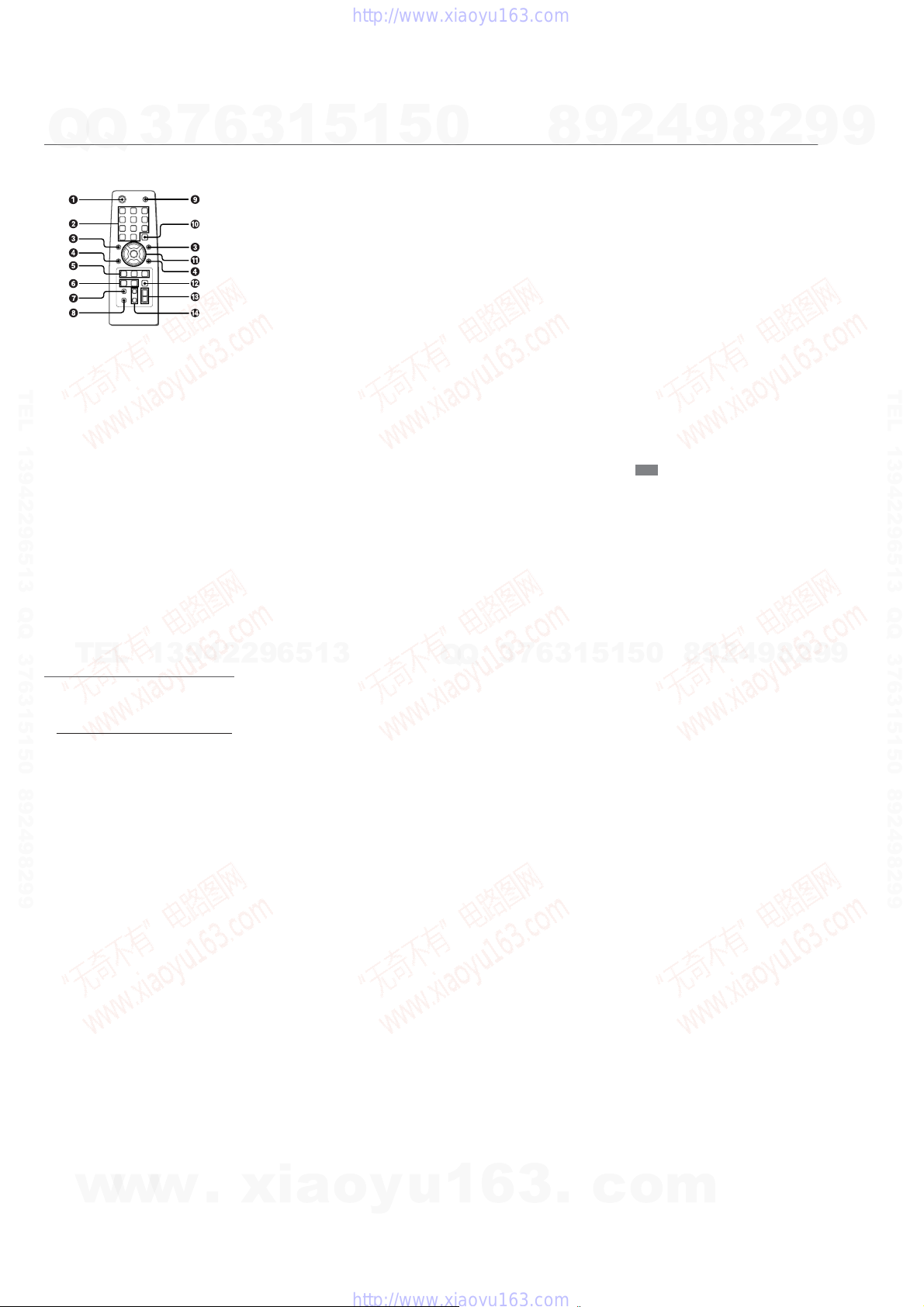
Remote control
Refer to the pages indicated in parentheses for details.
TEL 13942296513 QQ 376315150 892498299
3
6
1
5
3
Buttons with the same or similar names with the main unit
basically have the same function.
1 POWER
2 1-0/10, +10
Selects a CD track of the specified number.
The numbered buttons take on these functions below when pressed
together with SHIFT held down
EDIT
Enters Automatic CD dubbing mode when pressed in
stop mode.
BAND
Selects Tuner function and the radio band.
TAPE A/B
Selects Tape function, and deck A or B.
SPECTRUM
Changes the spectrum analyzer display.
TUNER MODE
Switches between stereo or monaural FM reception.
GEQ
Enters Graphic Equalizer setting mode.
TUNER MEMORY
Tuner: stores the received station in to preset.
SURROUND
Switches surround on and off.
1
:
5
0
3 r, t
4 ALBUM M/N
5 PLAY MODE
6 CLOCK/TIMER/SET
7 DISPLAY
8 SHIFT
CD: selects a track.
Tuner: selects a preset station.
BASS, MID and TREBLE: adjusts the level.
Clock and Timer: sets the time.
Selects a previous album or a succeeding album.
CD: selects a playback mode.
Tape: selects a playback mode
REPEAT
Enters CD repeat playback mode.
ENTER
Enters timer setting mode.
CLOCK/TIMER/SELECT
Selects timer playback, timer recording or timer off.
Displays the time and the remaining time for CD.
When the unit is off, press DISPLAY to switch between
DEMO, Clock and ECO display modes.
Hold down when pressing a numbered button to change
its function to that printed above the number.
e.g.)
“Press SHIFT+BAND on the remote” indicates “Hold
down SHIFT and press ‘2’ (BAND)”. Doing so makes you
be able to select Tuner function and the radio band.
8
9
4
2
9 FUNCTION
0 DISC SKIP
! c/d
@ SLEEP
# VOLUME (+, -)
$ SOUND
Note
The buttons not explained above (KARAOKE) do not
operate for this unit.
9
Switches the active function among CD, TAPE, TUNER
and VIDEO (MD).
Select a disc.
CD and Tape: starts playback.
s
CD and Tape: stops playback.
f, g
CD: searches a track in fast forward or fast reverse
playback when held down.
Tape: fast forwards or rewinds the tape.
Tuner: manually tunes down or up within the band.
a
CD and Tape: pauses playback.
Switches the sleep-timer on/off and selects the duration.
Adjusts the volume.
Selects BASS, MID or TREBLE setting mode
CLEAR
Clears a track of the CD programed playback.
8
2
9
9
TEL 13942296513 QQ 376315150 892498299
TEL
Setting the clock
Use the remote.
1
Press CLOCK/TIMER/SET .
Go to step 3 when the time appears and the ‘hour’ flashes.
2
Press r or t repeatedly until “ CLOCK ”
appears in the display and then press ENTER.
3
Press r or t repeatedly to set the hour
and then press ENTER.
4
Press r or t repeatedly to set
and then press ENTER.
The time display stops flashing and the clock starts from
00 seconds.
•MULTI JOG is also available in place of r or t.
To di splay the time
Press DISPLAY . The time will be displayed for 6 seconds.
Tip:
“AM 12:00” indicates midnight and “ PM
If “- -:- -” appears when the unit is turned off
There has been a power interruption. Re-set the clock.
13942296513
minute
the
12:00
” noon.
Q
Q
3
7
6
3
1
5
1
5
0
8
9
2
4
9
8
2
9
9
8
w
w
w
.
xia
o
y
u
1
6
3
.
c
o
m
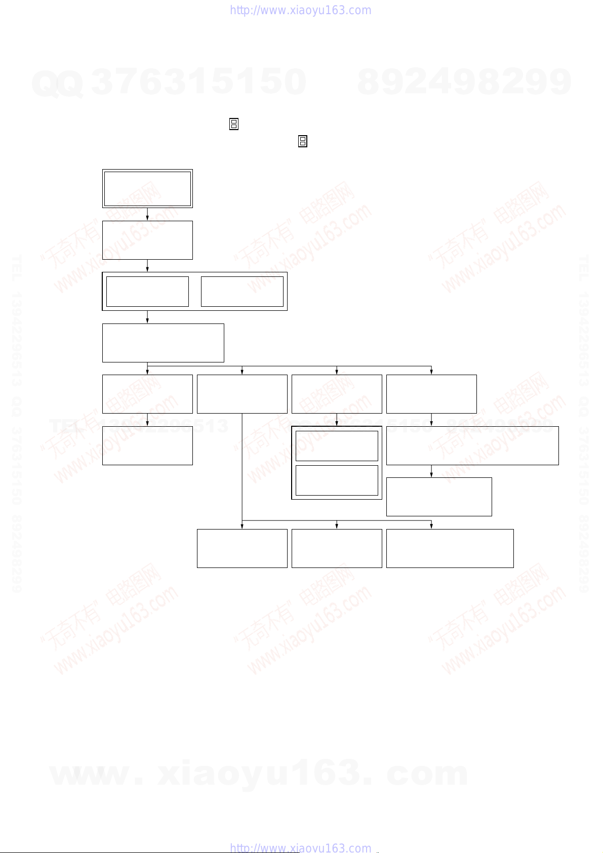
SECTION 3
DISASSEMBLY
• This set can be disassembled in the order shown below.
7
Q
Q
TEL 13942296513 QQ 376315150 892498299
3
3-1. DISASSEMBLY FLOW
Note 1: The process described in can be performed in any order.
Note 2: Without completing the process described in , the next process can not be performed.
6
Set
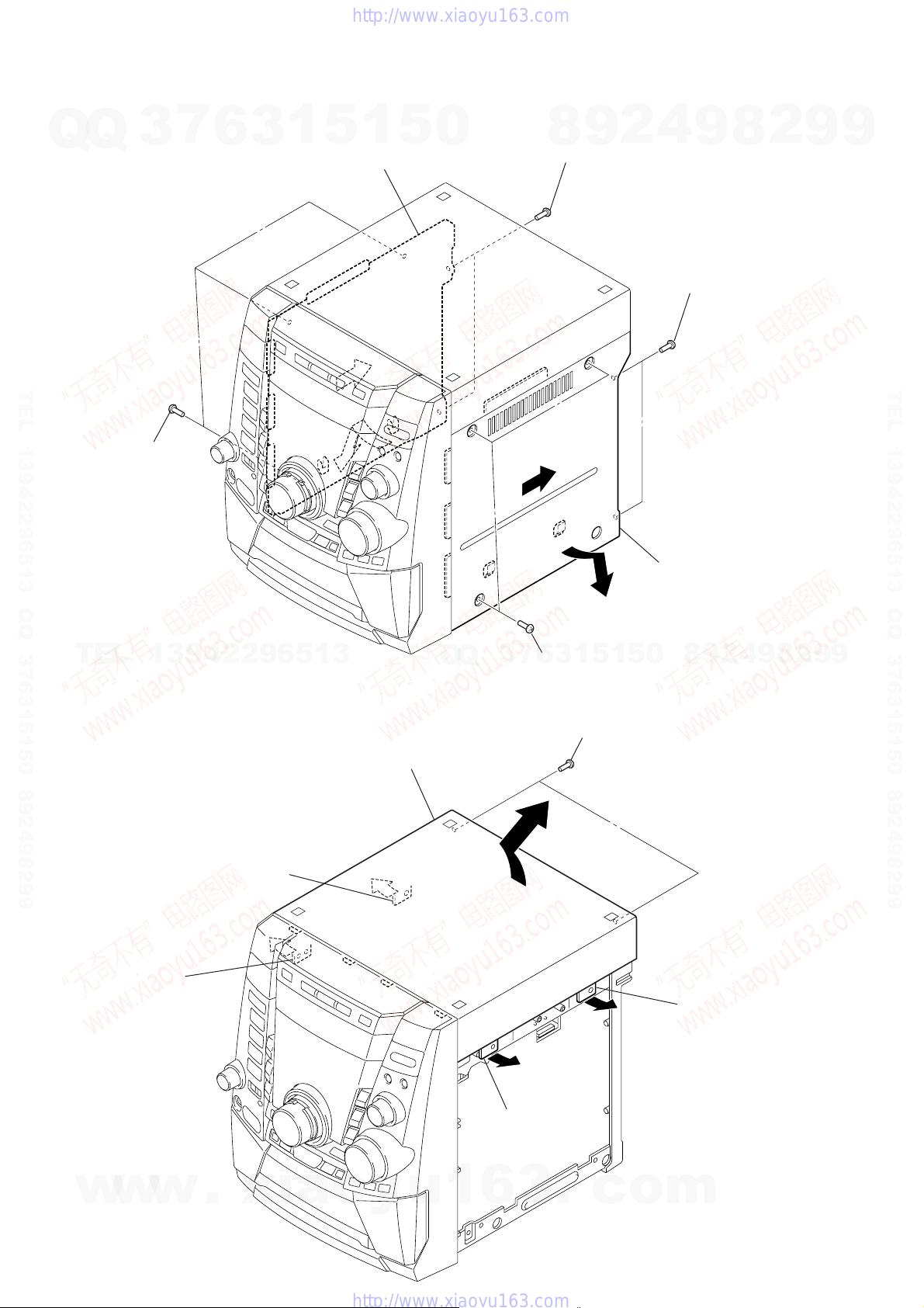
3-2. CASE
(SIDE-L/R)
(Page 10)
3
1
5
1
5
0
8
9
2
4
9
8
2
CX-JS7
9
9
TEL 13942296513 QQ 376315150 892498299
TEL
3-3. CASE (TOP)
(Page 10)
3-5. CD MECHANISM DECK
(CDM74F-K6BD71A)
(Page 11)
3-6. FRONT PANEL
SECTION
(Page 12)
13942296513
3-7. MECHANICAL
DECK
(Page 12)
3-4. TRAY PANEL
3-8. REAR CABINET
3-9. MAIN BOARD
(Page 11)
SECTION
(Page 13)
(Page 13)
3-12. TABLE ASSY
(Page 15)
7
3
Q
Q
3-13. MOTOR (TB)
BOARD
(Page 15)
3-14. MOTOR (LD)
BOARD
(Page 16)
3-10. POWER
BOARD
(Page 14)
6
3
3-15. BASE UNIT
(BU-K6BD71A)
(Page 16)
8
9
4
2
9
8
0
5
1
5
1
3-16. MOTOR GEAR ASSY (SLED) (M701),
BD BOARD
(Page 17)
3-17. OPTICAL PICK-UP
(KSS-213D)
(Page 17)
3-11. TRANSFORMER BOARD
(Page 14)
2
9
9
w
w
w
.
xia
o
y
u
1
6
3
.
c
o
m
9
CX-JS7
Note: Follow the disassembly procedure in the numerical order given.
7
Q
Q
3-2. CASE (SIDE-L/R)
3
6
3
1
5
0
case (side-L)
8
1
5
0
8
6
two screws
(BVTP3 × 10)
9
2
4
9
1
two screws
(BVTP3 × 10)
8
2
9
9
TEL 13942296513 QQ 376315150 892498299
7
three screws
(case3 TP2)
TEL
3-3. CASE (TOP)
13942296513
9
7
case (top)
Q
Q
3
7
3
3
6
2
three screws
(case3 TP2)
6
1
5
1
4
0
5
1
two screws
(BVTP3
×
5
case (side-R)
8
10)
9
2
4
9
8
2
9
TEL 13942296513 QQ 376315150 892498299
9
10
w
w
4
claw
w
5
.
xia
claw
3
o
y
u
1
6
3
claw
.
c
o
claw
2
m
Q
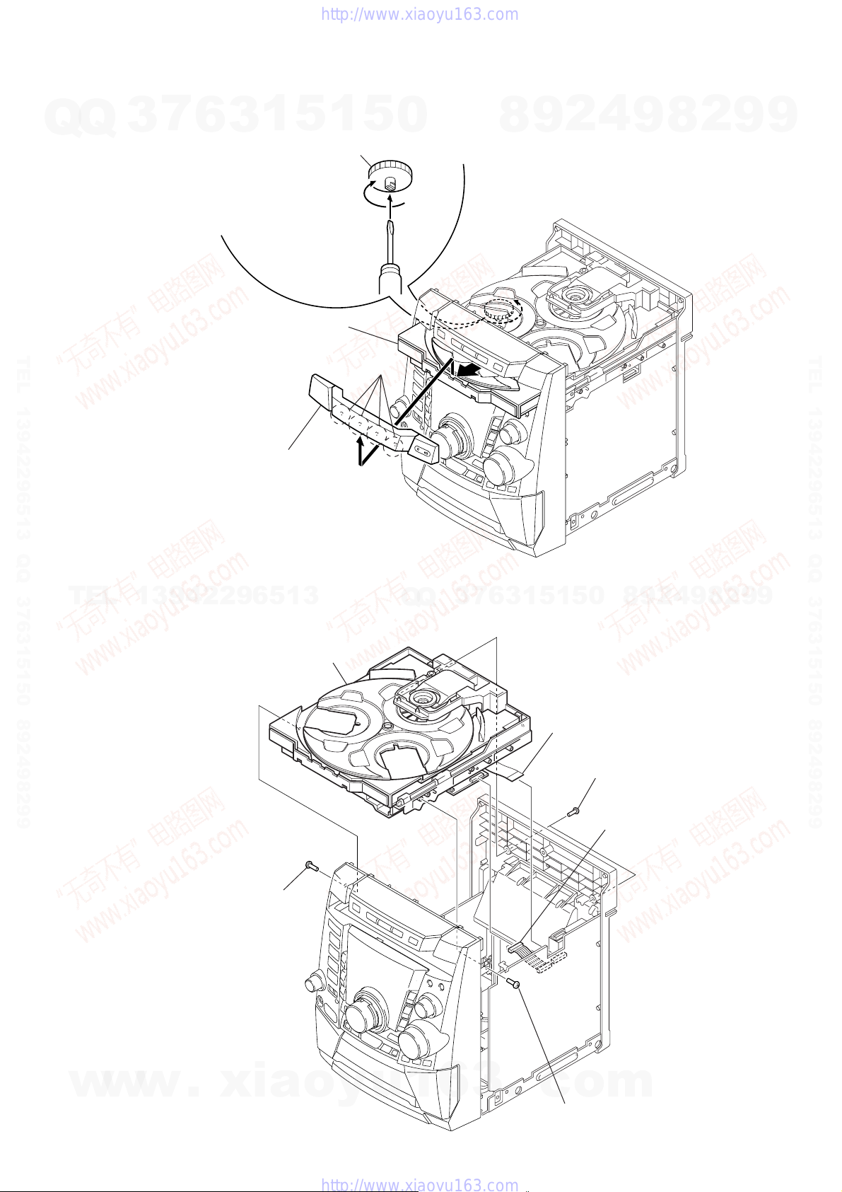
3-4. TRAY PANEL
7
Q
3
6
1
1
3
Turn the loading gear
in the direction of arrow A.
2
Pull-out the disc table.
5
1
5
0
A
8
9
2
4
9
8
2
CX-JS7
9
9
TEL 13942296513 QQ 376315150 892498299
3
four claws
tray panel
4
TEL
13942296513
3-5. CD MECHANISM DECK (CDM74F-K6BD71A)
6
CD mechanism deck
(CDM74F-K6BD71A)
Q
Q
3
7
6
3
1
0
5
1
5
1
wire (flat type) (19 core)
(CN312)
8
9
2
4
9
8
2
9
TEL 13942296513 QQ 376315150 892498299
9
w
w
w
4
screw (BVTP3 × 10)
.
xia
o
y
u
1
6
3
.
c
o
3
screw (BVTP3 × 10)
5
two screws
(BVTP3
2
connector (CN701)
m
×
10)
11
CX-JS7
)
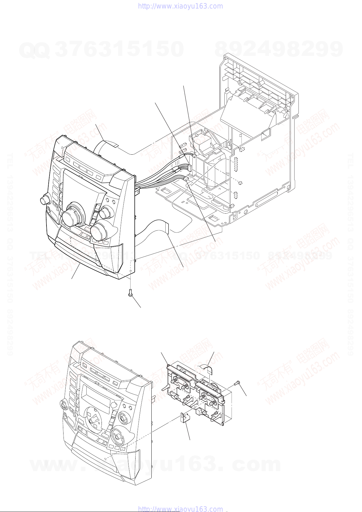
3-6. FRONT PANEL SECTION
7
Q
Q
3
6
3
5
wire (flat type) (9 core)
(CN311)
1
5
3
connector (CN202)
1
5
0
4
connector (CN203)
8
9
2
4
9
8
2
9
9
TEL 13942296513 QQ 376315150 892498299
TEL
7
13942296513
front panel section
6
three screws
(BVTP3
×
10)
7
3
Q
Q
1
wire (flat type) (31 core)
(CN304)
2
connector (CN310)
5
1
3
6
1
5
0
8
9
2
4
9
8
2
9
TEL 13942296513 QQ 376315150 892498299
9
3-7. MECHANICAL DECK
w
w
w
12
.
xia
3
mechanical deck
4
ground mechanical plate
o
y
u
1
6
1
wire (flat type) (13core)
3
.
c
2
six screws
(BVTP3
o
×
10
m
)
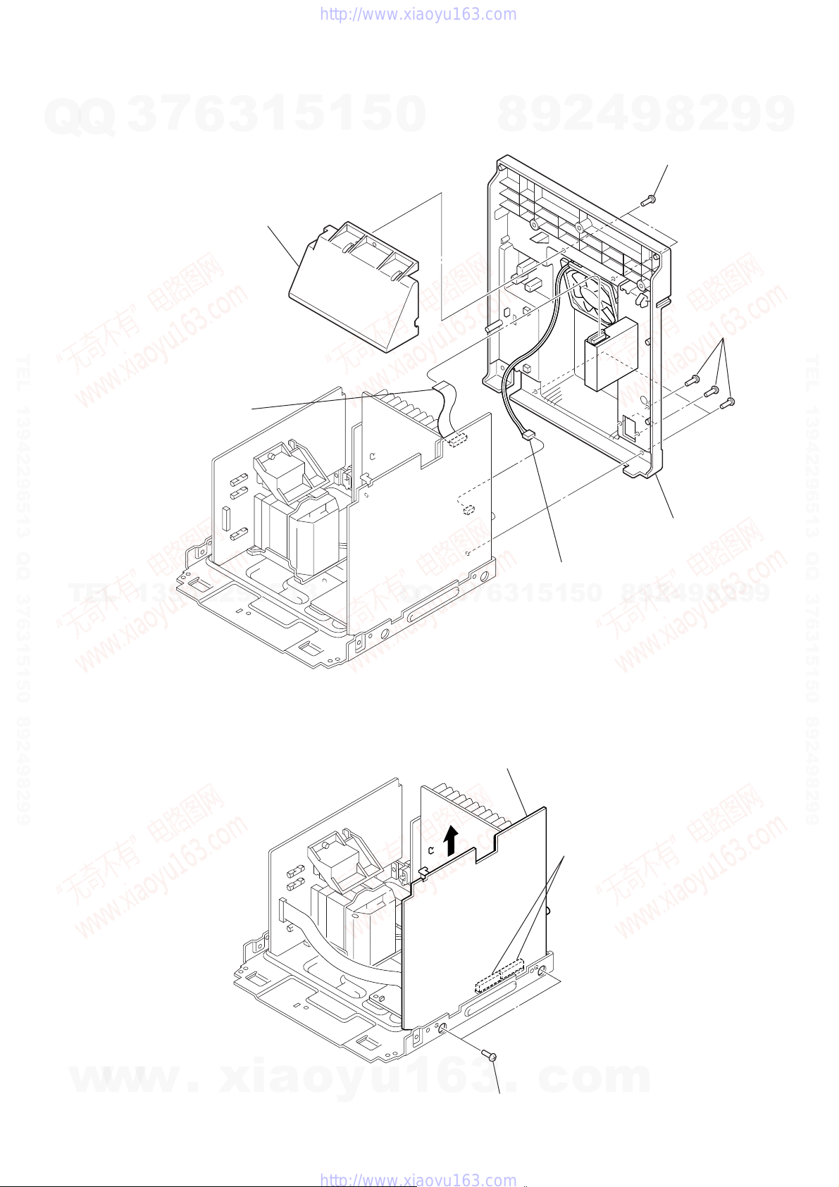
3-8. REAR CABINET SECTION
7
Q
Q
TEL 13942296513 QQ 376315150 892498299
3
1
wire (flat type) (11core)
6
4
cover (duct)
3
1
5
1
5
0
8
9
2
4
9
3
2
8
two screws
(BVTP3 × 10)
5
five screws
(BVTP3 × 10)
CX-JS7
9
9
TEL 13942296513 QQ 376315150 892498299
TEL
13942296513
3-9. MAIN BOARD
Q
Q
7
3
3
main board
6
3
2
connector (CN303)
5
1
5
1
2
two connectors
(CN502, CN503
0
6
rear cabinet section
4
2
9
8
9
8
2
9
9
w
w
w
.
xia
o
y
u
1
6
3
.
1
two screws
(BVTP3
c
×
10)
o
m
13
CX-JS7
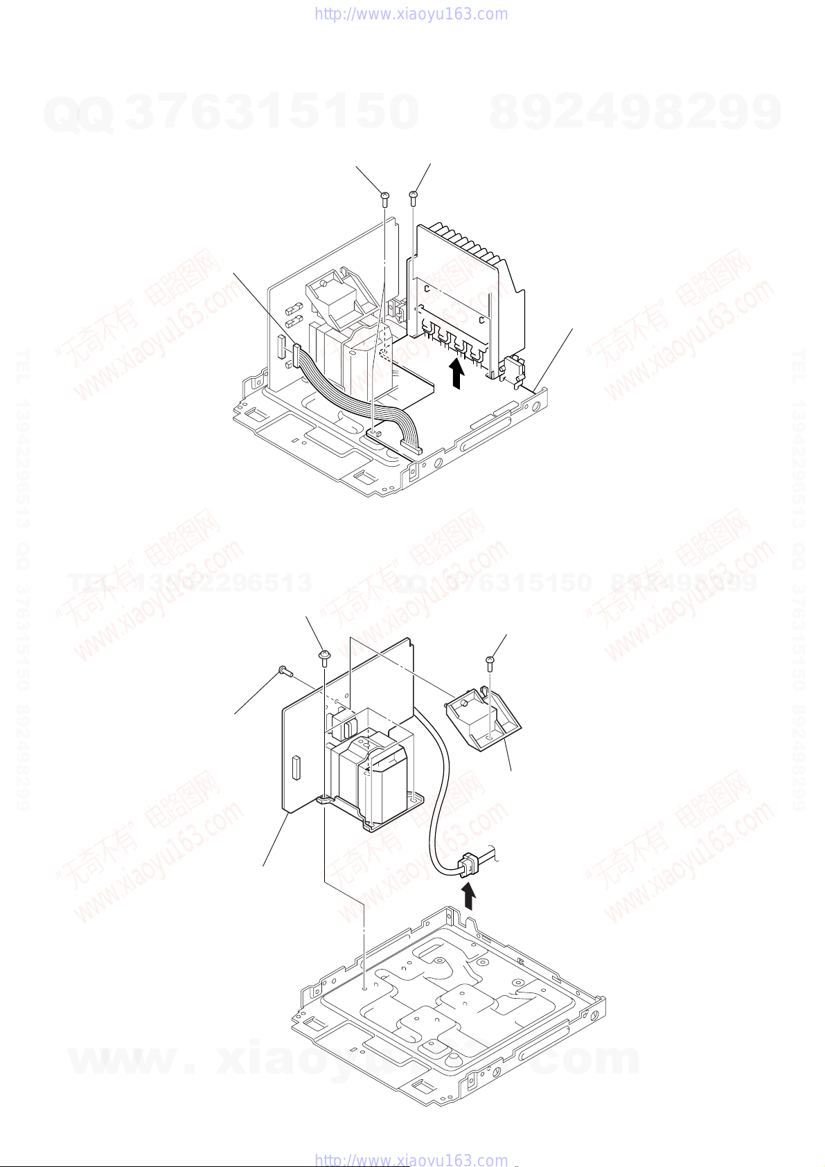
3-10. POWER BOARD
7
Q
Q
3
1
connector (CN902)
6
3
1
5
3
two screws
(BVIT3B+3-8R)
1
5
0
2
two screws
(BVIT3B+3-8R)
8
9
2
4
power board
4
9
8
2
9
9
TEL 13942296513 QQ 376315150 892498299
3-11. TRANSFORMER BOARD
TEL
13942296513
1
screw
(BVTP3
5
four screws
(ITC+4-10R)
×
10)
Q
Q
3
7
6
3
2
5
1
screw
(BVTT3
1
×
5
8)
0
8
9
2
4
9
8
2
9
TEL 13942296513 QQ 376315150 892498299
9
14
w
w
w
6
transformer board
.
xia
o
y
u
1
6
3
4
.
3
trans holder
c
o
m
)
d
Q
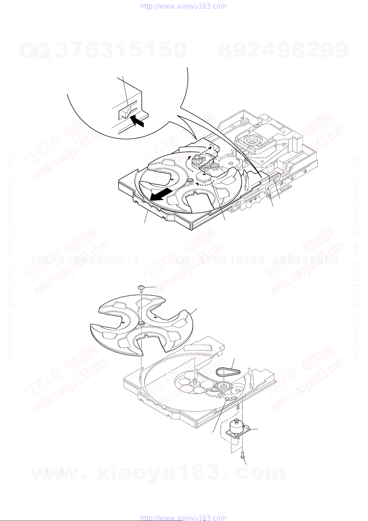
3-12. TABLE ASSY
7
Q
3
6
3
1
5
5
1
5
0
two claws
8
9
2
4
9
8
2
CX-JS7
Ver. 1.2
9
9
TEL 13942296513 QQ 376315150 892498299
A
2
Pull-out the table assy.
6
table assy
TEL
13942296513
3-13. MOTOR (TB) BOARD
Q
1
screw
(PTPWH M2.6)
Q
2
3
7
tray
1
Turn the loading gear
in the direction of arrow
1
5
1
3
6
5
0
4
hook
3
wire (flat type) (5 core
(CN702)
A
.
9
4
2
9
8
8
2
9
TEL 13942296513 QQ 376315150 892498299
9
w
w
w
.
xia
4
connector
(CN731)
o
y
u
1
6
3
3
belt (table)
6
motor (TB) boar
5
.
c
two screws
(BTTP M2.6)
o
m
15
CX-JS7
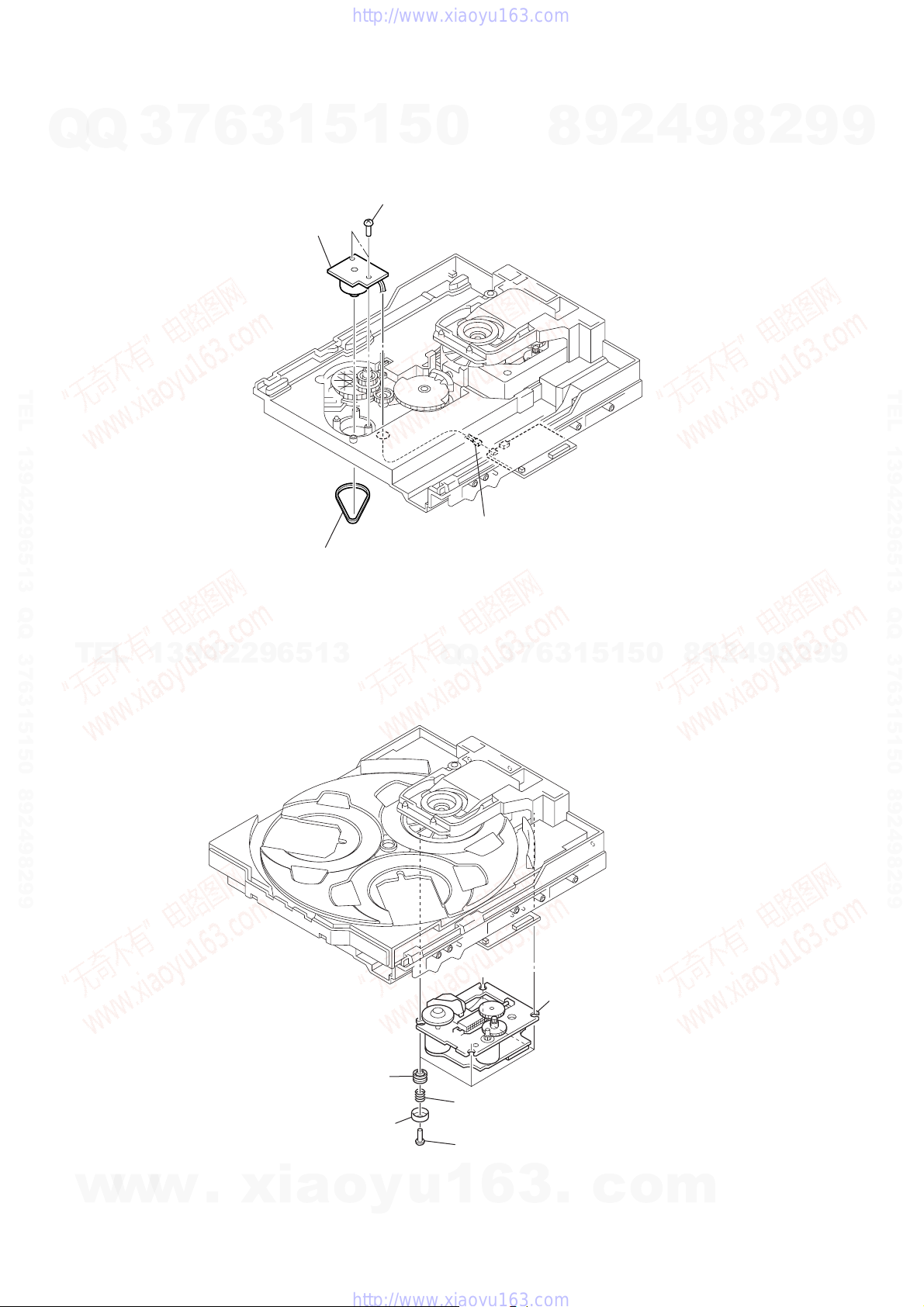
3-14. MOTOR (LD) BOARD
7
Q
Q
3
6
4
1
3
motor (LD) board
5
1
5
3
two screws
(BTTP M2.6)
0
8
9
2
4
9
8
2
9
9
TEL 13942296513 QQ 376315150 892498299
2
connector
Q
(CN704)
7
3
1
TEL
3-15. BASE UNIT (BU-K6BD71A)
13942296513
belt (loading)
Q
6
3
1
5
1
5
0
8
9
2
4
9
8
2
9
TEL 13942296513 QQ 376315150 892498299
9
16
w
w
w
.
xia
4
four insulators
2
four stoppers (BU)
o
5
3
four coil springs
(insulator)
1
four screws
(BTTP M2.6)
y
u
1
6
3
.
base unit
(BU-K6BD71A)
c
o
m
)
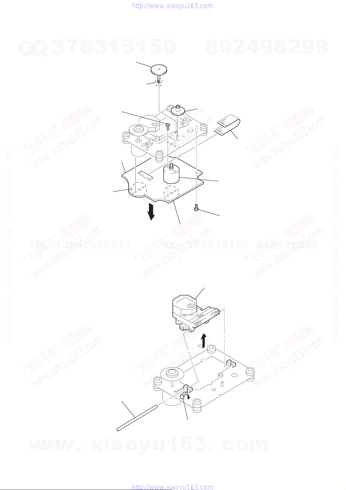
3-16. MOTOR GEAR ASSY (SLED) (M701), BD BOARD
7
Q
Q
TEL 13942296513 QQ 376315150 892498299
3
6
2
1
3
two screws
×
3)
(P2
qa
BD board
7
5
gear (A)
6
1
claw
5
0
8
8
gear (B)
9
4
2
5
9
wire (flat type) (16 core
(CN708)
8
2
CX-JS7
9
9
TEL 13942296513 QQ 376315150 892498299
1
Remove two
solders.
TEL
13942296513
3-17. OPTICAL PICK-UP (KSS-213D)
4
Q
9
Remove two solders.
7
3
Q
0
motor gear assy (SLED)
(M701)
3
screw (P2.6 × 6)
0
5
1
5
1
3
6
3
Remove the optical pick-up
(KSS-213D) in the direction
of arrow
B
B
.
8
9
2
4
9
8
2
9
9
w
w
w
.
xia
2
sled shaft
A
1
Slide the lever
in the direction of arrow
o
y
u
1
6
3
.
c
A
.
o
m
17
CX-JS7
SECTION 4
TEST MODE
[COLD RESET]
• The cold reset clears all data including preset data stored in the
Q
Q
RAM to initial conditions. Execute this mode when returning
the set to the customer.
Procedure:
1. Press the [POWER] key to turn the power ON.
2. Press three keys of x , [ENTER] and [POWER] simultaneously.
3. The message “RESET” is displayed on the fluorescent indicator
tube momentarily, then becomes standby states.
[TUNER STEP CHANGE-OVER]
• A step of AM channels can be changed over between 9 kHz and
10 kHz.
Procedure:
1. Press the [POWER] key to turn the power ON.
2. Press the [TUNER BAND] key to select “AM”.
TEL 13942296513 QQ 376315150 892498299
3. Press the [POWER] key to turn the power OFF.
4. Press two keys of [ENTER] and [POWER] simultaneously.
5. The message “9K STEP” or “10K STEP” is displayed on the
fluorescent indicator tube, and thus the channel step is changed
over.
[CD SHIP MODE]
• This mode moves the optical pick-up to the position durable to
vibration. Use this mode when returning the set to the customer
after repair.
Procedure:
1. Press the [POWER] key to turn the power ON.
2. Press the [CD] key to select “CD”.
3. Press two keys of [CD] and [POWER] simultaneously.
4. The message “LOCK” is displayed on the fluorescent indicator
tube, and the CD ship mode is set.
TEL
[CHANGE-OVER FUNCTION OF MD/VIDEO]
• This mode is used to enable function of external input to change
over between MD and VIDEO.
Procedure:
1. Set to standby state.
2. Press two keys of [MD VIDEO ]
3. The message “MD” or “VIDEO”is displayed on the fluorescent
indicator tube, and the function of external input is changed
over.
3
7
6
3
1
13942296513
)(
and [POWER] simultaneously.
5
1
5
[CD TRAY LOCK MODE]
• This mode is used to unable to take sample disc out of tray in
0
the shop.
Procedure:
1. Press the [POWER] key to turn the power ON.
2. Press the [CD] key to select “CD”.
3. While pressing the x key, press the Z key for 5 seconds.
4. The message “LOCKED” is displayed on the fluorescent
indicator tube and the tray is locked. (Even if pressing
the Z key, the message “LOCKED” is displayed on the
fluorescent indicator tube and the tray is locked)
5. To release from this mode, while pressing the x key, press
the Z key for 5 seconds.
6. The message “UNLOCKED” is displayed on the fluorescent
indicator tube and the tray is unlocked.
[AMP TEST MODE]
• This mode is used to set the parameter of AMP IC and EQ band
level and i-bass IC.
Procedure:
1. Press the [POWER] key to turn the power ON.
2. Press three keys of x , [HIP HOP] and [HEAVY] simultaneously.
3. When the AMP test mode is activated, the message “AMP
TEST” is displayed on the fluorescent indicator tube
momentarily.
4. Press two keys of [HEAVY] and [DISC DIRECT PLAY 2]
simultaneously, mode is changed over to parameter setting of
AMP IC and EQ band level and i-bass IC.
5. In the AMP IC setting mode, press the [ENTER] key, surround
ON/OFF is changed over.
6. In the EQ band level setting mode, press the [MANUAL] key,
EQ band is changed over to LOW, MID or HIGH.
7
7. In the i-bass IC setting mode, turn the
Q
8. To r elease from this mode, press two keys of [HEAVY] and
3
Q
i-bass level, press the [i-BASS] key, i-bass f0 level is change
over between 1 to 3.
[TECHNO] simultaneously.
8
6
3
9
1
5
2
1
5
4
9
2
9
8
0
[BASS] knob, up/down
8
4
2
9
8
9
2
9
9
TEL 13942296513 QQ 376315150 892498299
9
18
w
w
w
.
xia
o
y
u
1
6
3
.
c
o
m
CX-JS7
[AGING MODE]
Q
TEL 13942296513 QQ 376315150 892498299
• This mode can be used for operation check of CD section and
Q
tape deck section.
CD section and tape deck section work in parallel.
If an error occurred:
The aging operation stops only an error occurred sections and
display then status.
If no error occurs:
The aging operation continues repeatedly.
Procedure:
1. Press the [POWER] key to turn the power ON.
2. Press the [CD] key to select “CD”.
3. Set disc on the tray and set tape into the deck.
4. Set the “ALL DISCS” mode and “REV OFF” mode.
5. Press three keys of x , [HEAVY] and [DISC CHANGE/DISC SKIP]
simultaneously.
6. The message “AGING” is displayed on the fluorescent indicator
tube momentarily, then aging operations of CD and tape are
started at the same time.
7. To release from this mode, operate the “COLD RESET”.
1. Display at the Aging Mode
Display operating state of CD section and tape deck section
alternately.
If an error occurred, stop display which that section.
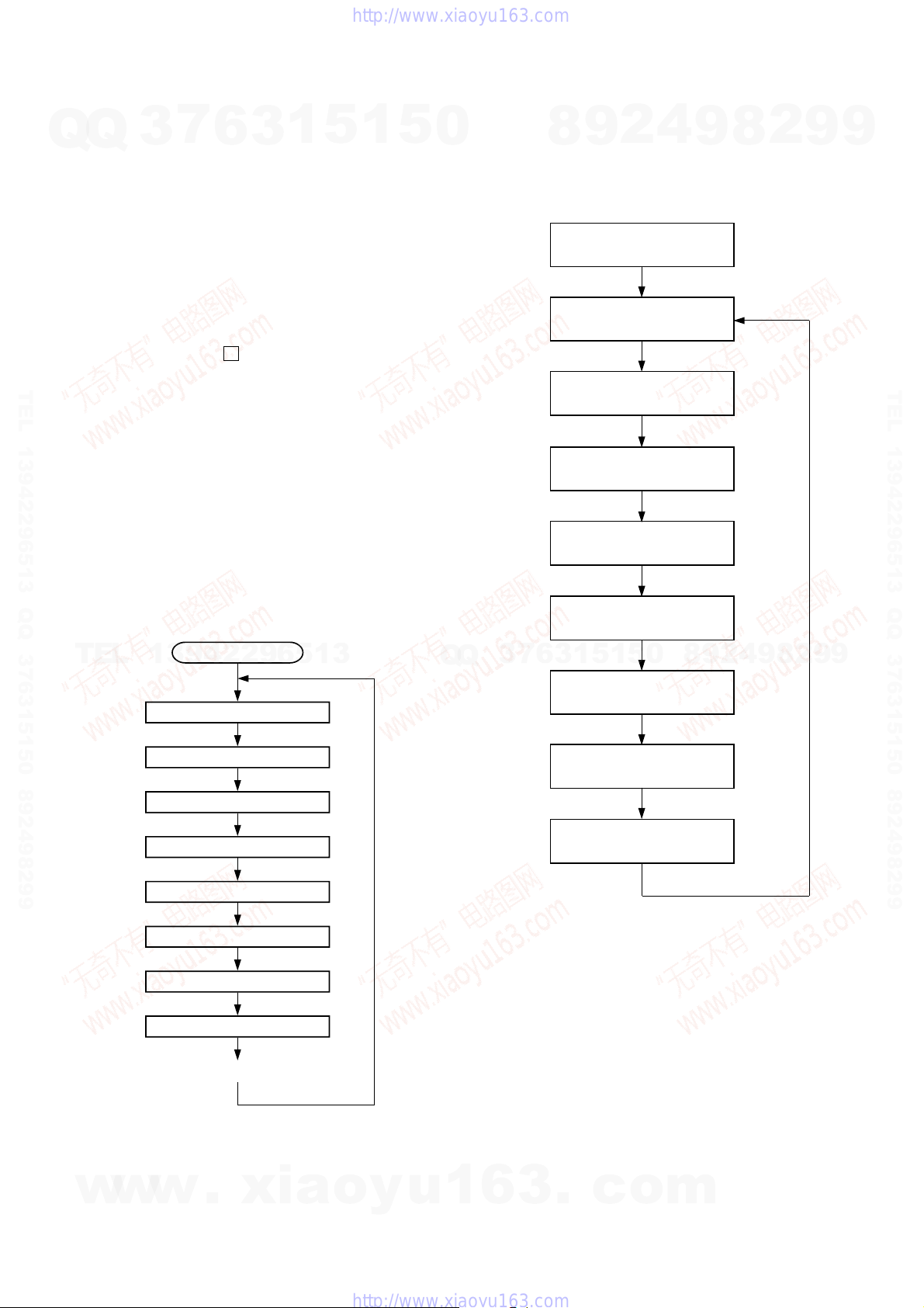
2. CD Section
The sequence during the aging mode is following as below.
Display at the aging mode is the same as the normal operation.
Aging mode sequence (CD section) :
3
7
6
3
1
5
1
5
0
3. Tape Deck Section
The sequence during the aging mode is following as below.
If an error occurred, stop display that step.
Aging mode sequence (tape deck section) :
2
9
8
Rewind the tape A and B
“AAG-1 or 2”
FWD play the tape A
“AAG-3”
Fast forward the tape A
“AAG-4”
REV play the tape A
“AAG-5”
Rewind the tape A
“AAG-6”
FWD play the tape B
“BAG-3”
4
9
Shut off
2 minutes
Shut off or 20 seconds
2 minutes
Shut off
8
2
9
9
TEL 13942296513 QQ 376315150 892498299
TEL
Start (from disc 1)
13942296513
Disc chucking
TOC read
Play first track for 2 seconds
Play last track for 2 seconds
EX-change open/close
Open the disc tray
Disc skip
Close the tray
Change the next disc.
Q
Q
2 minutes
0
5
1
5
1
3
6
7
3
Fast forward the tape B
“BAG-4”
Shut off or 20 seconds
REV play the tape B
“BAG-5”
2 minutes
Rewind the tape B
“BAG-6”
Shut off
Note: “*AG-*” is display of each step.
8
9
2
4
9
8
2
9
9
w
w
w
.
xia
o
y
u
1
6
3
.
c
o
m
19

CX-JS7
[GC TEST MODE]
• This mode is used to check the fluorescent indicator tube, LED
Q
Q
and key.
Procedure:
1. Press the [POWER] key to turn the power ON.
2. Press three keys of x , [HEAVY] and [DISC DIRECT PLAY 2]
simultaneously.
3. Fluorescent indicator tube and LEDs are all turned ON.
4. Press two keys of [HEAVY] and [DISC DIRECT PLAY 2]
simultaneously, mode is changed over.
5. In the key check mode, press each key, the defined key number
of every each key list is displayed on the fluorescent indicator
tube.
6. In the key count check mode, “K-CNT 0” is displayed on the
fluorescent indicator tube. Each time a key is pressed, “K” value
TEL 13942296513 QQ 376315150 892498299
increases. However, once a key is pressed, it is no longer taken
into account.
7. In the headphone input check mode, connect the headphone,
the message “H_P ON” is displayed on the fluorescent indicator
tube, and disconnect the headphone, the message “H_P OFF”
is displayed on the fluorescent indicator tube.
8. In the volume check mode, turn the [VOLUME] knob, the
display on the fluorescent indicator tube is changed over to
“VOL UP”, “VOL FLAT” or “VOL DOWN”
[MC TEST MODE]
• This mode is used to check operations of Amplifier.
Procedure:
1. Press the [POWER] key to turn the power ON.
2. Press three keys of x , [HEAVY] and [DISC DIRECT PLAY 3]
simultaneously.
3. When the MC test mode is activated, the message “MC MODE”
is displayed on the fluorescent indicator tube momentarily, then
TEL
VACS level is displayed on the fluorescent indicator tube.
4. Press the
indicator tube is changed over to “EQ MAX”, press the
[MANUAL] key, the display on the fluorescent indicator tube
is changed over to “EQ MID”, press the [HIP HOP] key, the
display on the fluorescent indicator tube is changed over to
“EQ MIN”,
5. Turn the [VOLUME] knob, the displa y on the fluorescent
indicator tube is changed over to “VOL MAX”, “VOL MID” or
“VOL MIN”
6. When the [REC PAUSE/START] key is pressed with a tape
set in the deck-B, the function is switched “MD” or “VIDEO”
and recording starts. When the m or M key is pressed
during recording, the tape is rewound back to the beginning of
recording, the function is switched to “T APE B”, then playback
starts.
7. When the [CD SYNC] key is pr essed with the test tape (AMS100, AMS-110A) in the deck, number of space between tunes
is counted, then if AMS-110A is set, “OK” is displayed on the
fluorescent indicator tube and if AMS-100 is set, “NG” is
displayed on the fluorescent indicator tube.
8. To release from this mode , press the [POWER] key.
[TECHNO] key, the display on the fluorescent
3
7
6
3
1
13942296513
5
1
5
[MODEL, DESTINATION AND VERSION DISPLAY]
• This mode is used to check the model, destination and software
0
version.
Procedure:
1. Set to the standby state.
2. Press three keys of x , [TECHNO] and [HEAVY] simultaneously.
3. When the model, destination and version display mode is
activated, the model an destination is displayed on the
fluorescent indicator tube.
4. Press two keys of [HEAVY] and [DISC DIRECT PLAY 2]
simultaneously, mode is changed over to model and destination
display mode and version display mode.
5. In the version display mode, press the [DISC DIRECT PLAY 3]
key, display is changed over to version display and year, month
and day of the software creation display.
6. To release from this mode, press the two keys of [TECHNO]
and [HEAVY] simultaneously.
[CD SERVICE MODE]
• This mode can run the CD sled motor freely. Use this mode, for
instance, when cleaning the optical pick-up.
Procedure:
1. Press the [POWER] key to turn the power ON.
2. Press the [CD] key to select “CD”.
3. Press three keys of x , [HEAVY] and Z simultaneously.
4. When the CD service mode is activated, the message “TRVS
ON” is displayed on the fluorescent indicator tube.
5. Press the M key, optical pick-up move to outside track and
the message “SLED OUT” is displayed on the fluorescent
indicator tube.
6. Press the m key, optical pick-up move to inside track and
the message “SLED IN” is displayed on the fluorescent
indicator tube..
7
3
Q
Q
7. Press the
[5 REPEAT LIMIT CANCEL]
• Number of repeat for CD playback is 5 times when the repeat
mode is “REPEAT”. This mode is used to enables CD to repeat
playback for limitless times.
Procedure:
1. Press the [POWER] key to turn the power ON.
2. Press the [CD] key to select “CD”.
3. Press three keys of x , [HEAVY] and Y simultaneously.
[TECHNO] key, traverse ON/OFF is changed over.
8
6
3
9
1
5
2
1
5
4
0
9
8
9
8
2
4
2
9
8
9
2
9
9
TEL 13942296513 QQ 376315150 892498299
9
20
w
w
w
.
xia
o
y
u
1
6
3
.
c
o
m
p
p
SECTION 5
ELECTRICAL ADJUSTMENTS
CX-JS7
CD SECTION
Q
Note:
1. CD Block is basically designed to operate without adjustment. Therefore,
2. Use YEDS-18 (3-702-101-01) unless otherwise indicated.
3. Use an oscilloscope with more than 10MΩ impedance.
4. Clean the object lens by an applicator with neutral detergent when the
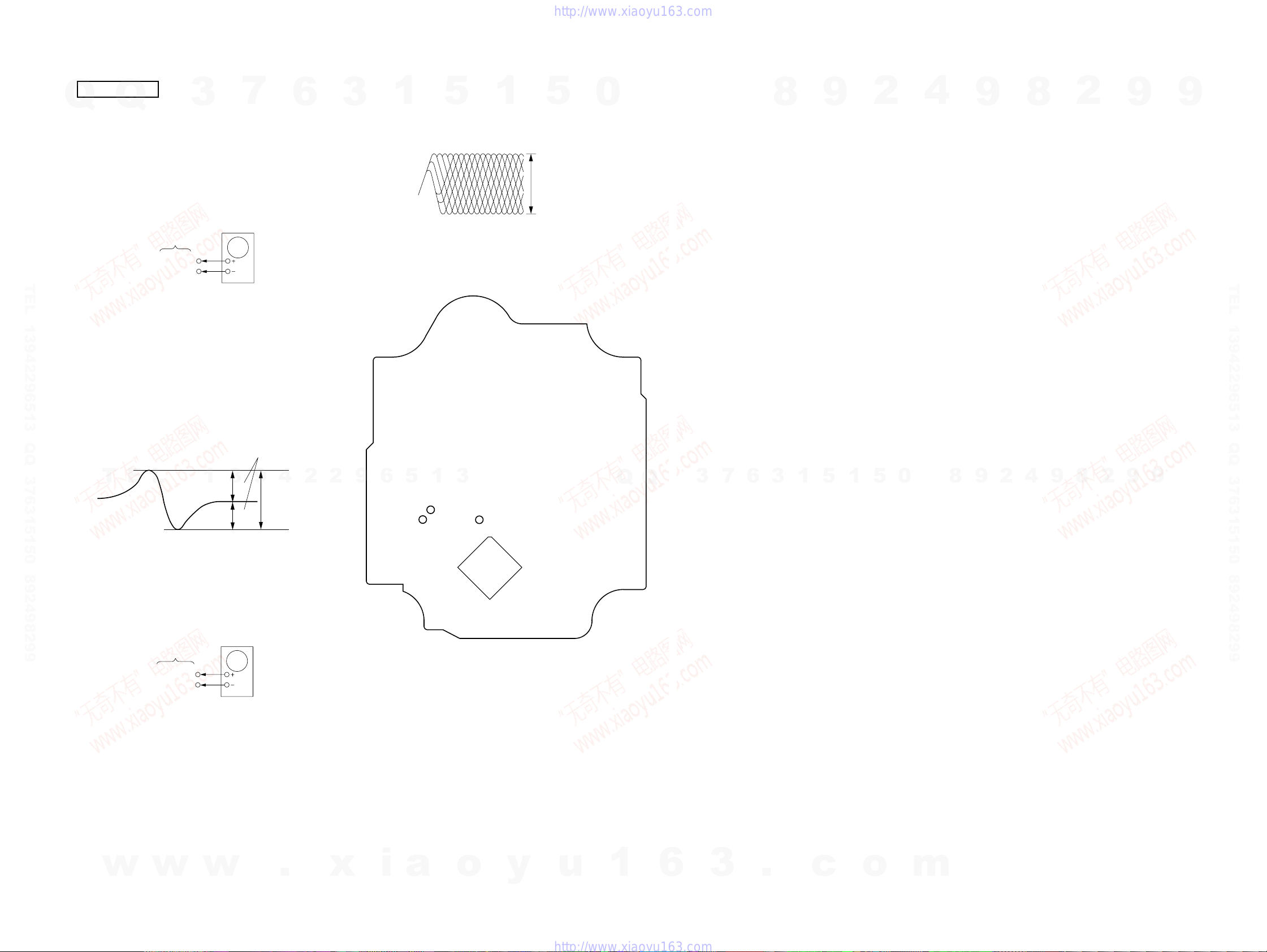
S-CURVE CHECK
TEL 13942296513 QQ 376315150 892498299
Procedure :
1. Connect an oscilloscope to TP (FE) and TP (VC).
2. Turn the power on.
3. Load a disc (YEDS-18) and actuate the focus search. (In
4. Confirm that the oscilloscope waveform (S-curve) is
Q
check each item in order given.
signal level is low than specified value with the following checks.
consequence of open and close the disc tray, actuate the focus
search)
symmetrical between A and B. And confirm peak to peak level
within 3 ± 0.5 Vp-p.
3
BD board
TP(FE)
TP(VC)
7
Oscilloscope
6
Note: Clear RF signal waveform means that the shape “ ◊ ” can be clearly
3
1
Connecting Location: BD board
– BD Board (Conductor side) –
distinguished at the center of the waveform.
5
RF signal waveform
1
5
VOLT/DIV : 200mV
TIME/DIV : 500ns
level : 1.3
±
0.3Vp-
0
8
9
2
4
9
8
2
9
9
TEL 13942296513 QQ 376315150 892498299
S-curve waveform
symmetry
T
E
L
Note: •Try to measure several times to make sure than the ratio
of A : B or B : A is more than 10 : 7.
•Take sweep time as long as possible and light up the
brightness to obtain best waveform.
RF LEVEL CHECK
BD board
TP(RF)
TP(VC)
Procedure :
1. Connect an oscilloscope to TP (RF) and TP (VC).
2. Turn the power on.
3. Load a disc (YEDS-18) and playback.
4. Confirm that oscilloscope waveform is clear and check if RF
signal level is correct or not.
1
3
oscilloscope
9
4
2
±
0.5Vp-
2
A
within 3
B
9
6
TP (FE)
5
TP (VC)
1
3
TP (RF)
IC721
Q
Q
3
7
6
3
1
5
1
5
0
8
9
2
4
9
8
2
9
9
w
w
w
.
x
i
a
o
y
u
1
6
2121
3
.
c
o
m
CX-JS7
SECTION 6
DIAGRAMS
6-1. BLOCK DIAGRAM – CD Section –
Q
Q
DETECTOR
A
B
3
A
D
C
D
C
I-V AMP
B
7
6
3
FIN2
8
FIN1
7
1
RF AMP
TEL 13942296513 QQ 376315150 892498299
E
F
LASER DIODE
PD
E
F
LD
LD
PD
AUTOMATIC
POWER CONTROL
Q701
TIN1
9
TIN2
10
LDD
80
LDS
79
APC
TBAL
EQ,
AGC
5
RF
PH, BH
A/D
CONVERTER
SERVO
PROCESSOR
D/A
CONVERTER
1
4
5
RF AMP, FOCUS/TRACKING ERROR AMP,
DIGITAL SIGNAL PROCESSOR, DIGIRAL SERVO PROCESSOR,
EFMIN
3
ERROR
CORRECT
0
DIGITAL FILTER, D/A CONVERTER
IC721
D/A
CONVERTER
EXTERNAL
AUDIO IN
SERIAL OUT
CLOCK
GENERATOR
FSX/16MIN
LCHO
RCHO
ASDFIN
ASDACK
ASLRCK
DATA
DATACK
LRSY
EFLG
C2F
16MOUT
XIN
XOUT
42
45
57
56
55
60
59
58
53
52
50
26MP3RES
54
49
48
16.9344MHz
X701
R-CH
8
9
2 ADDATA
3 ADBCK
4 ADLRCK
79 DATAIN
80 DATACK
1 LRSY
5 C2FIN
9 CKOUT
78 RESB
7 CKIN
73 CMDOUT
74 CMDIN
75 CL
2
MP3 DECODER
IC801
CE
76 66
MDATA0
– MDATA15
MADRS0
– MADRS8
FSYNC
4
23-30, 33-4060-53, 50
9
• R-ch is omitted due to same as L-ch.
• SIGNAL PATH
: CD PLAY
IC802
MEMORY
2-5, 7-10,
I/01 – I/016
31-34, 36-39
A0 – A8
16-19, 22-26
27 OE45OEB
13 WE42WEB
14 RAS41RASB
29 LCAS43CASLB
28 UCAS44CASUB
8
2
MUTING
Q311
R-CH
MUTING CONTROL
SWITCH
Q312
9
CD-L
A
9
(Page 24)
TEL 13942296513 QQ 376315150 892498299
OPTICAL PICK-UP
BLOCK
T
E
(KSM-213DCP)
2-AXIS
DEVICE
(FOCUS)
L
(TRACKING)
1
3
9
4
S701
(LIMIT)
FOCUS/TRACKING COIL DRIVE,
SPINDLE/SLED MOTOR DRIVE
VO3(+)
18
17 VO3(–)
11 VO2(+)
12 VO2(–)
IC722
2
FOIN
2
70 LIMIT SW
20TIN
10
9
6
5
TDO
FDO23SLDO22SPDO25CONT4
20
21
1
3
Q
COMMAND
INTERFACE
Q
*WRQ
72CD MUTE
9
9
2
8
9
4
2
9
3
DO
64
DI
63
CL
62
CE
61
65
67DRF
66*RES
99 I-LC78646/LC78684 DI
98 O-LC78646/LC78684 DO
100 O-LC78646/LC78684 CLK
5O-LC78646 CE
85 I-WRQ
86 I-CD DRF
4O-LC78646 RESET
SYSTEM CONTROLLER
M751
(LOADING)
IC901 (1/2)
M
106
O-LC78684 CE
I-LC78684 SYNC
0
5
1
5
1
3
6
7
8
94O-POWER RELAY
29I-HOLD
11RESET
27I-POWER DOWN
96I-CD NUMBER SENS
I-BU IP DOWN/
CD OPEN CLOSE
LOADING MOTOR DRIVE
4 OUT1
2 OUT2
22
IC701
1O-SYS-MUTE
7FIN
9RIN
S-MUTE
O-POWER
HOLD
RESET
POWER DOWN
LEVEL SHIFT
Q731
+
LM-F
LM-R
OPEN
CLOSE
ROTARY
ENCODER
S711
O-POWER, HOLD
POWER DOWN
TABLE ADDRESS
SENSOR
IC731
DISC TRAY
ADDRESS DETECT
S751
OPEN/CLOSE
DETECT
LM-F, LM-R,
TM-F, TM-R
S-MUTE,
RESET,
B
C
D
(Page 24)
(Page 24)
(Page 23)
w
w
(SPINDLE)
M701
(SLED)
M702
M
M
w
26 VO4(+)
27 VO4(–)
2 VO1(+)
1 VO1(–)
.
25SLIN
3SPIN
x
7LDS
i
a
o
y
u
1
6
2222
3
.
c
M741
(TABLE)
M
o
TABLE MOTOR DRIVE
IC712
4 OUT1
2 OUT2
m
TM-F
7FIN
TM-R
9RIN

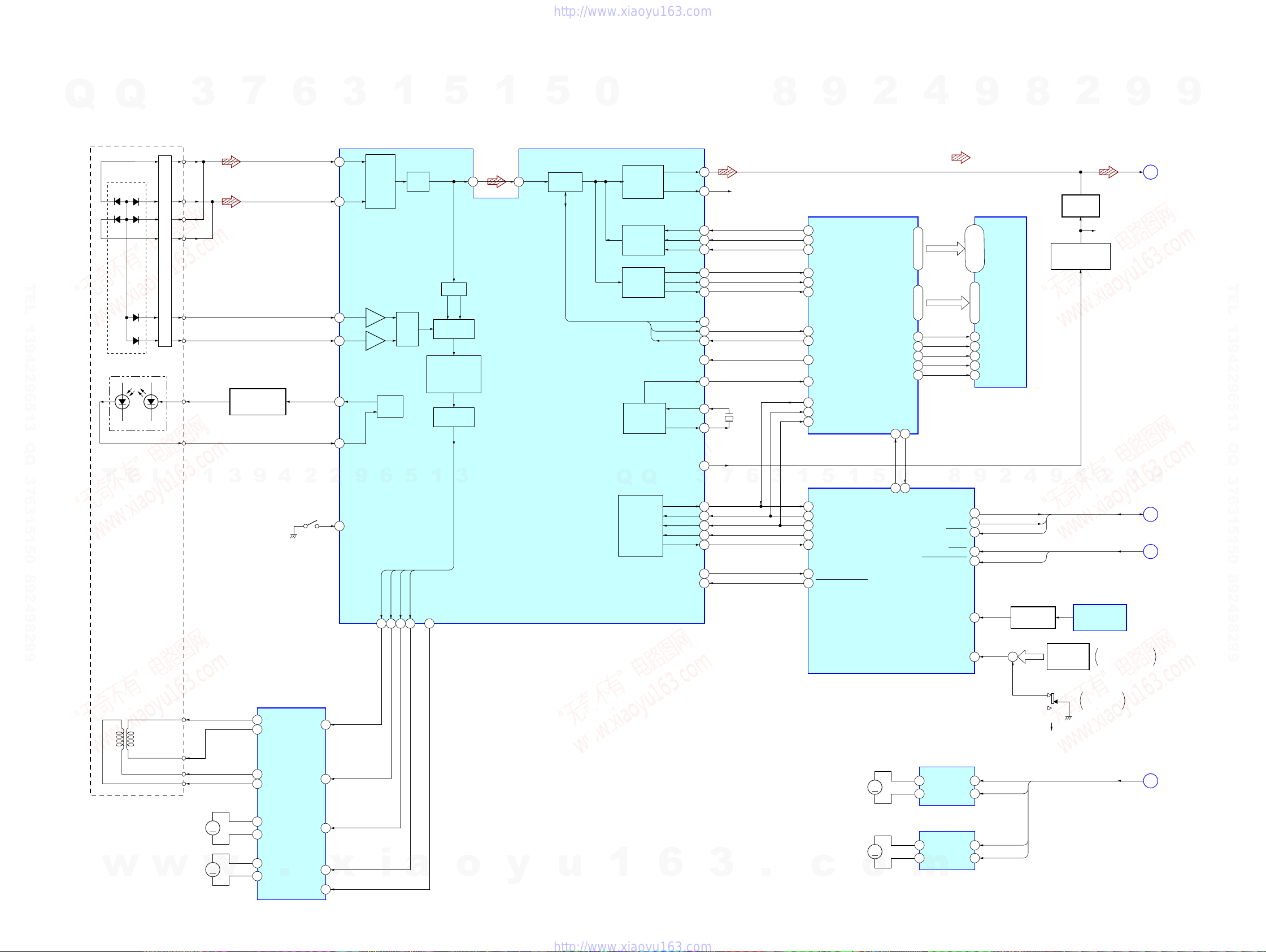
6-2. BLOCK DIAGRAM – TUNER/TAPE/PANEL Section –
CX-JS7
Q
TEL 13942296513 QQ 376315150 892498299
(Page 24)
(Page 24)
Q
L-CH
HP1
(PB)
(DECK-A)
HRPE1
(REC/PB/ERASE)
(DECK-B)
FM 75Ω
(COAXIAL)
AM LOOP
• R-ch is omitted due to same as L-ch.
• SIGNAL PATH
R-CH R-CH
L-CH
R-CH R-CH
ERASE
ANTENNA
T
E
L
SA
E
HP
F
: TUNER (FM/AM)
: TAPE PLAY (DECK-A)
: TAPE PLAY (DECK-B)
w
: REC
w
3
R-CH
TUNER UNIT
FM ANT
AM ANT
1
w
7
MUTING
Q219, 221
L-CH
R-CH R-CH
DI
DO
CLK
CE
3
9
TUNED
ST
TU-MUTE
SPEANA AMP
Q201, 202
(FRONT PANEL KEY)
+3.3V (SUB)
4
VOLUME
BASS
MULTI JOG
TREBLE
MIDDLE
S301 – 309,
S311 – 331
.
6
REC ON/OFF
SWITCH
Q222, 225
2
REMOTE CONTROL
3
2
BAND-PASS
FILTER
Q204 – 206
RECEIVER
IC802
ROTARY
ENCODER
S801
ROTARY
ENCODER
S802
ROTARY
ENCODER
S803
ROTARY
ENCODER
S804
KEY ACTIVE
SWITCH
Q504, 505
x
BIAS OSC
9
1
L201
BIAS OSC
Q223
DI
CLK
91 O-LC72121/M61529/BU2099 DO
87 I-LC72121 DI
92 O-LC72121/BU2099 CLK
9 O-LC72121 CE
6
88 I-TUNER TUNE
97 I-TUNER STEREO
18 I-SPEANA L
19 I-SPEANA M
20 I-SPEANA H
76 I-HP MUTE
28 I-RMC
84 I-VOL A
83 I-VOL B
80 I-BASS A
79 I-BASS B
82 I-JOG A
81 I-JOG B
78 I-TRE A
77 I-TRE B
26 – 24
i
+4V
REC BIAS
SWITCH
SYSTEM CONTROLLER
5
1
I-KEY1 –
I-KEY3
a
5
Q228
IC901 (2/2)
+9V
O-BU2099 LCK
O-M61529 CLK
3
O-KEYSCAN
S7/I-A-PHOTO
S8/I-A-HALF
S6/I-A-MODE
S9/I-B-MODE
I-REC (FWD)
S10/I-REC (REW)
o
DECK A/B SELECT SWITCH, REC/PB EQ AMP
1
32
34
21
CF1
CF2
I-B-PHOTO
I-B-HALF
S1 – S5,
S11 – S23
G1 – G11
XT1
y
AIN (L)
BIN (L)
RECOUT (L)
8
7
1312XT2
15
16
93O-POWER LED
95
48
52
49
53
47
54
50
55
41 – 45, 56 – 6830 – 40
5
S7/U5
S8/U6
S6/U4
S9/U10
S10/U11
EQ
X901
32.768kHz
X902
8.64MHz
U8
U9
U7
u
IC201
0
EQOUT (L)
REC-IN (L)
MUTE-ON/OFF
REC MUTE-ON/OFF
Q
LED901
POWER 1 STANDBY/ON
B+
D603 – 610
S6 – S10
FLUORESCENT
INDICATOR TUBE
1
28 27
24
13
A/B
14
15
Q
B+ SWITCH
Q921
FL902
6
8
9
10
7 BIAS
6 REC
11 TUNER MUTE
DI
MCLK
3
+3.3V
DISC DIRECT PLAY
3
MUTE
TAI (L)
MULTI CONTROLLER
IC309
A/B
PB MUTE
REC MUTE
FRONT SPON/OFF
LM-L (CD)
LM-R (CD)
TM-L (CD)
TM-R (CD)
LCK
CLK
S-OUT
6
7
LED201
LED202
TUNER BAND
LED203
MD (VIDEO)
LED204
TAPE A/B
LED301
LED302
LED303
LED213
i-BASS
.
8
16
13
12
15
14
18SO
3
CD
1
2
3
PB-OUT (L)
3DATA
4CLOCK
5LCK
SO
1
9
26
LM-F
LM-R
TM-F
TM-R
LCK
CLK
S-OUT
3 DATA
4 CLOCK
5 LCK
18 SO
1
5
6CD
7 TUNER
8 AUX
9 TAPE
LED DRIVER
3 DATA
4 CLOCK
5 LCK
18 SO
6 CD1
7 CD2
8 CD3
9 I-BASS
LED DRIVER,
TAPE MECHANISM CONTROLLER
c
o
2
5
IC201
MOTOR
IC202
0
A-SOL
B-SOL
4
TAPE-L
15MANUAL
14HIP POP
13TECHNO
12SALSA
11VOCAL
10HEAVY
10
11
12
m
9
REC-L
LED211
MANUAL
LED210
HIP POP
9
8
LED208
TECHNO
LED207
SALSA
LED206
VOCAL
LED205
HEAVY
CAPSTAN/REEL
MOTOR DRIVE
Q601
PLUNGER DRIVE
(DECK-A)
Q602
PLUNGER DRIVE
(DECK-B)
Q603
8
TAPE-L, REC-L
LM-F, LM-R, TM-F, TM-R
DI, SO, CLK, MCLK, LCK,
4
2
TAPE MECHANISM
CAPM+
(CAPSTAN/REEL)
A-SOL
B-SOL
U5
U8
U6
U9
U4
U10
U7
U11
A-PHOTO
B-PHOTO
A-HALF
B-HALF
A-MODE
B-MODE
REC (FWD)
REC (REW)
SP-F
TUNER-L
9
DECK BLOCK
MM
(DECK-A)
(DECK-B)
2
G
H
D
J
K
8
(Page 24)
(Page 24)
(Page 22)
(Page 24)
(Page 24)
2
9
9
9
TEL 13942296513 QQ 376315150 892498299
9
2323
CX-JS7
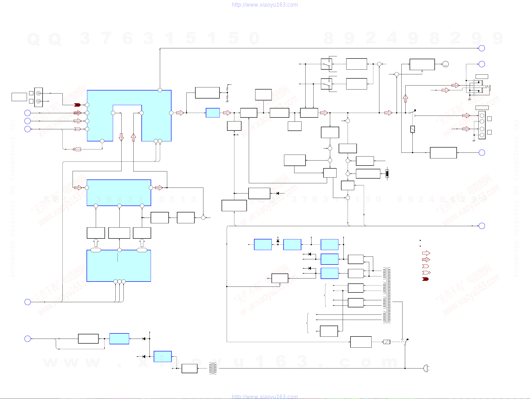
6-3. BLOCK DIAGRAM – AMP/POWER SUPPLY Section –
MD-L
CD-L
TUNER-L
TAPE-L
INA
3
VREF
14
FREQUENCY
CONTROL
Q314 – 316
12 – 10
CTRL1 –
CTRL3
BASS BOOST
CONTROLLER
IC310
7
INPUT SELECTSWITCH, TONE CONTROL,
ELECTRICAL VOLUME, BASS BOOST AMP
TOUT
RECB-2
35
BASS BOOST ENHANCER
9
6
IC301
29
IC303
4
BBE
7
BASS BOOST
ON/OFF SWITCH
Q323
9
I-BASS
DATA4CLOCK
3
5
LCK
CLK
SO
LCK
2
28
OUTA
2
13
BASS BOOST
CONTROL
Q317 – 320
16 – 13
BB CTRL1 –
BB CTRL4
3
VOLIN2
6
9
GIN
Q
MD (VIDEO)
(Page 22)
TEL 13942296513 QQ 376315150 892498299
(Page 23)
(Page 23)
(Page 23)
L
IN
R
CD-L
A
TUNER-L
J
TAPE-L, REC-L TAPE-L
G
DI, SO, CLK,
MCLK, LCK
K
JK302
Q
T
R-CH
E
REC-L
L
3
37
40
39
38
1
1
19
SAOUT
OUT2
DATA22CLOCK
21
MCLK
DI
6
BASS BOOST
CONTROL
Q492
1
25
5
5
1
FEED BACK
SWITCH
Q491
CENTER VOLATAGE
GENERATOR
3
+
1
Q324
BUFFER
IC304
R-CH
5
VM+10V
MUTING
Q525
MUTING CONTROL
SWITCH
Q527
S-MUTE
O-POWER
+1.8V (MP3)
PRE DRIVE
Q517, 519
R-CH
0
CURRENT
MIRROR
Q521, 523
POWER OFF
MUTING DRIVER
Q529, 530
Q
+1.8V
REGULATOR
IC803
VCC
CASCADE
Q511, 513, 515
D513
Q
+3.3V
(MAIN)
B+ SWITCH
Q301, 302
R-CH
R-CH
BIAS
Q507, 509
OVER CURRENT
DETECT
Q13
VM+10V
3
+4V
REGULATOR
IC306
P+7V
DECK+9V, M+9V
VM+9V
VM+10V
SWITCHING
SWITCHING
Q17, 19, 22
–VP
+VP
FINAL DRIVE
Q501, 503
6
7
D313 – 315
D102
POWER AMP
BLOCK
Q18
TO
R-CH
REGULATOR
REGULATOR
REGULATOR
8
OVER LOAD
DETECT
Q505
+
+
HOLD
Q12
3
+9V
IC305
+9V
IC308
+10V
IC313
+VH
–VH
+VL
–VL
R-CH
1
+VH
+VL
–VH
–VL
DC DETECT
RELAY B++9V
9
OUTPUT LEVEL
DETECT
Q20, 21
OUTPUT LEVEL
DETECT
Q23, 24
+
Q5, 6
+
+
HOLD
Q7 – 9
+
5
HOLD
HOLD
RECT
D301 – 304
RECT
D319 – 322
RECT
RECT
2
DC DETECT
Q329
THERMAL DETECT
Q10, 11
5
1
O-POWER
O-POWER
D1
D2
4
+
R-CH
RELAY B+
0
MAIN POWER
TRANSFORMER
PT901
VM
VM
VH
VH
VL
VL
R-CH
TH501,
502
+
8
9
ON/OFF SWITCH
Q327, 328, 372, 373
9
8
FAN MOTOR
R-CH
RY501
4
2
R-ch is omitted due to same as L-ch.
SIGNAL PATH
M
R-CH
SPEAKER ON/OFF
RELAY DRIVE
Q304
9
: TUNER (FM/AM)
: CD PLAY
: TAPE PLAY
: REC
: MD (VIDEO) IN
2
M731
(FAN)
8
S-MUTE, O-POWER, HOLD
2
9
SP-F
9
SA
HP
E
F
J221
PHONES
JK502
SPEAKER
+
–
+
–
H
9
B
9
(Page 23)
(Page 23)
L
R
(Page 23)
(Page 22)
TEL 13942296513 QQ 376315150 892498299
(Page 22)
RESET,
POWER DOWN
C
w
RESET
POWER DOWN
w
RESET SWITCH
Q901
w
RESET SIGNAL
GENERATOR
IC502
+3.3V (SUB)
.
D504
x
+4V
+4V
REGULATOR
IC501
i
EVER+10V
a
o
RECT
D902 – 905
SUB POWER
TRANSFORMER
PT902
y
TO
FLUORESCENT
INDICATOR TUBE
u
1
6
2424
3
VF1
VF2
–VFL
REGULATOR
Q533 – 536
.
–30V
c
POWER ON/OFF
RELAY DRIVE
Q330, 331
o
RY902
m
(AC IN)
 Loading...