


5-025-709-33(1)
XAV-AX8150(EUR)
https://rd1.sony.net/help/ev/xav-ax81/h_zz/
AV RECEIVER
To cancel the demonstration (Demo) display, see page 6.
Pour annuler la démonstration (Démo), reportez-vous à la
page 6.
Zum Deaktivieren der Demo-Anzeige (Demo) schlagen Sie
bitte auf Seite 6 nach.
Para cancelar la pantalla de demostración (Demostración),
consulte la página 6.
Om de demonstratie (Demo) te annuleren, zie pagina 7.
Se sidan 6 för att avbryta demonstrationsvisningen (Demo).
Operating Instructions
Mode d’emploi
Bedienungsanleitung
Manual de instrucciones
Gebruiksaanwijzing
Bruksanvisning
GB
FR
DE
ES
NL
SE
XAV-AX8150

Warning
For safety, be sure to install this unit in the
da
rd of the car as the rear side of the unit
shboa
becomes hot during use.
For details, see “Connection/Installation”
(page 10).
Made in Thailand
The nameplate indicating operating voltage, etc., is
locat
ed on the bottom of the chassis.
The validity of the CE marking is restricted to only
those countries where it is legally enforced, mainly
in the countries EEA (European Economic Area) and
Switzerland. The validity of the UKCA marking is
restricted to only those countries where it is legally
enforced, mainly in the UK.
WARNING
To prevent fire or shock hazard, do not
expose the unit to rain or moisture.
To avoid electrical shock, do not open the
cabinet. Refer servicing to qualified personnel
only.
Notice for customers: the following
nforma
tion is only applicable to equipment
i
sold in countries applying EU directives and/
or UK applying relevant statutory
requirements
This product has been manufactured by or on
behalf of Sony Corporation.
EU Importer: Sony Europe B.V.
Inquiries to the EU Importer or related to product
complia
nce in Europe should be sent to the
manufacturer’s authorized representative, Sony
Belgium, bijkantoor van Sony Europe B.V., Da
Vincilaan 7-D1, 1930 Zaventem, Belgium.
Hereby, Sony Corporation declares that this
e
EU.
The full text of the EU declaration of conformity is
availab
https://compliance.sony.eu
Hereby, Sony Corporation declares that this
equipmen
statutory requirements.
The full text of the declaration of conformity is
availab
https://compliance.sony.co.uk
t is in compliance with Directive 2014/53/
quipmen
le at the following internet address:
t is in compliance with the UK relevant
le at the following internet address:
Disposal of waste batteries and
electrical and electronic
equipme
nt (applicable in the
European Union and other
countries with separate collection
systems)
This symbol on the product, the battery or on the
packaging indicates that the product and the
battery shall not be treated as household waste.
On certain batteries this symbol might be used in
combi
nation with a chemical symbol. The chemical
symbol for lead (Pb) is added if the battery contains
more than 0.004% lead.
By ensuring that these products and batteries are
dispos
ed of correctly, you will help to prevent
potentially negative consequences for the
environment and human health which could be
caused by inappropriate waste handling. The
recycling of the materials will help to conserve
natural resources.
In case of products that for safety, performance or
da
connection with an incorporated battery, this
battery should be replaced by qualified service staff
only.
To ensure that the battery and the electrical and
electr
over these products at end-of-life to the
appropriate collection point for the recycling of
electrical and electronic equipment.
For all other batteries, please view the section on
how to re
Hand the battery over to the appropriate collection
point for the recycling of waste batteries.
For more detailed information about recycling of
th
Civic Office, your household waste disposal service
or the shop where you purchased the product or
battery.
rity reasons require a permanent
ta integ
onic equipment will be treated properly, hand
move the battery from the product safely.
uct or battery, please contact your local
is prod
Warning if your car’s ignition has no ACC
position
Do not install this unit in a car that has no ACC
position. The display of the unit does not turn off
even after turning the ignition off, and this
causes battery drain.
Disclaimer regarding services offered by third
parties
Services offered by third parties may be changed,
suspended, or terminated without prior notice.
Sony does not bear any responsibility in these sorts
of situations.
2GB

Important notice
Caution
IN NO EVENT SHALL SONY BE LIABLE FOR ANY
INCIDENTAL, INDIRECT OR CONSEQUENTIAL
DAMAGES OR OTHER DAMAGES INCLUDING,
WITHOUT LIMITATION, LOSS OF PROFITS, LOSS OF
REVENUE, LOSS OF DATA, LOSS OF USE OF THE
PRODUCT OR ANY ASSOCIATED EQUIPMENT,
DOWNTIME, AND PURCHASER’S TIME RELATED TO
OR ARISING OUT OF THE USE OF THIS PRODUCT, ITS
HARDWARE AND/OR ITS SOFTWARE.
Dear customer, this product includes a radio
transmi
tter.
According to UNECE Regulation no. 10, a vehicle
manuf
acturers may impose specific conditions for
installation of radio transmitters into vehicles.
Please check your vehicle operation manual or
contac
t the manufacturer of your vehicle or your
vehicle dealer, before you install this product into
your vehicle.
Emergency calls
This BLUETOOTH car handsfree and the electronic
device connected to the handsfree operate using
radio signals, cellular, and landline networks as well
as user-programmed function, which cannot
guarantee connection under all conditions.
Therefore do not rely solely upon any electronic
device
for essential communications (such as
medical emergencies).
On BLUETOOTH communication
•Microwaves emitting from a BLUETOOTH device
may affect the operation of electronic medical
devices. Turn off this unit and other BLUETOOTH
devices in the following locations, as it may cause
an accident.
– where inflammable gas is present, in a hospital,
train, a
irplane, or petrol station
– near automatic doors or a fire alarm
•This unit supports security capabilities that
comply w
a secure connection when the BLUETOOTH
wireless technology is used, but security may not
be enough depending on the setting. Be careful
when communicating using BLUETOOTH wireless
technology.
• We do not take any responsibility for the leakage
o
communication.
If you have any questions or problems concerning
your unit that a
consult your nearest Sony dealer.
ith the BLUETOOTH standard to provide
rmation during BLUETOOTH
f info
re not covered in this manual,
3GB

vM
HOME ATTVOL VOICEOPTION
Guide to Parts and Controls
Main Unit
The VOL (volume) + button has a tactile dot.
Display/touch screen
HOME
Disp
lays the HOME screen (page 5).
STANDBY
Press and hold to turn the unit to standby mode
(USB c
harging is still available). To resume, press
any button.
VOL (volume) +/–
ATT (atten uate)
Atten
uates the sound.
To cancel, press again, or press VOL +.
MONITOR OFF
Press and hold to turn off the monitor.
To turn back on, touch any part of the display.
Re
ceptor for the remote commander
4GB
OPTION
lays the OPTION screen (page 5).
Disp
/ (previ
Functions differently depending on the selected
source:
– [
Radio]/[DAB+]: select a preset station.
– [USB]/
file.
Press and hold to:
– [Radio]: tune into a station automatically
(SEEK+/S
– [DAB+]: select a station (when [Seek By] is set
to [A-Z])/search for a station (when [Seek By]
is set to [Station Gp]).
– [USB]/[Bluetooth]: fast-reverse/fast-forward.
VO
ICE
vates the voice command function for Apple
Acti
CarPla
y and Android Auto™.
HDMI terminal (input)
ous/next)
[Bluetooth]: move to the previous/next
EEK–).

Screen Displays
Playback screen:
HOME screen:
OPTION screen:
Status indication
Lights up when the sound is attenuated.
Lights up when AF (Alternative
Frequencies) is available.
Lights up when the current traffic
informat
ion (TA: Traffic Announcement)
is available.
Lights up when a DAB announcement is
availab
le.
Indicates the signal strength status of
the DAB r
adio.
Lights up when the Bluetooth® signal is
on. Flash
es when the connection is in
progress.
Lights up when the audio device is
playab
le by enabling the A2DP
(Advanced Audio Distribution Profile).
Lights up when handsfree calling is
av
le by enabling the HFP (Handsfree
ailab
Profile).
Indicates the signal strength status of
the conn
ected mobile phone.
Indicates the remaining battery status of
the conn
ected mobile phone.
(source option)
Opens the source option menu. The available
items
differ depending on the source.
Application specific area
Displ
ays playback controls/indications or show
the unit’
s status. Displayed items differ
depending on the source.
Clock
Displa
ys the time which are set on the Date/
Time se
tting.
(return to the playback screen)
Switches from the HOME screen to the playback
screen.
5GB

Sources and Settings select keys
Changes the source or make various settings.
Flick to select the setting icon and other icons.
Touch the source icon you want to select.
Android
Auto
DAB+ Bluetooth Phone
USB WebLi nk HDMI
Rear
Camera
Sound select keys
Chan
ges the sound.
(EXTRA BASS)
Changes the EXTRA BASS setting.
(EQ10/Subwoofer)
Changes the EQ10/Subwoofer setting.
(monitor off)
Turns off the monitor. When the monitor is
tur
ff, touch any part of the display to turn it
ned o
back on.
Apple
CarPlay
Settings
Radio
Basic Operations
Pairing with a BLUETOOTH Device
When connecting a BLUETOOTH device for the first
time, mutual registration (called “pairing”) is
required. Pairing enables this unit and other devices
to recognize each other.
1 Press HOME, then touch [Settings]
[Bluetooth] [Bluetooth Connection] [ON]
[Pairing].
flashes while the unit is in pairing standby
mode.
2 Perform pairing on the BLUETOOTH device
so it detects this unit.
3 Select your model name shown on the
display of the BLUETOOTH device*.
When pairing is made, stays lit.
* If passkey input is required on the BLUETOOTH device,
input [0000].
Connecting Rear View Camera
By connecting the optional rear view camera to the
CAMERA IN terminal, you can display the picture
from the rear view camera. For details, see
“Connection/Installation” (page 10).
To display the picture from the rear view
camera
Press HOME, then touch [Rear Camera].
6GB
Canceling the Demonstration
Mode
1 Press HOME, then touch [Settings].
2 Touch [General], then touch [Demo] to set to
[OFF].
3 To exit the setup menu, touch (back)
twice.
Updating the Firmware
To update the firmware, visit the support site, then
follow the online instructions.
URL: https://www.sony.eu/support
Note
During the update, do not remove the USB device.

Additional Information
Precautions
•Power antenna (aerial) extends automatically.
•When you transfer ownership or dispose of your
car with
the unit installed, initialize all the settings
to the factory settings by performing the factory
reset.
• Do not splash liquid onto the unit.
Notes on safety
•Comply with your local traffic rules, laws, and
regulations.
•While driving
– Do not watch or operate the unit, as it may lead
to distra
ction and cause an accident. Park your
car in a safe place to watch or operate the unit.
– Do not use the setup feature or any other
function
which could divert your attention from
the road.
– When backing up your car, be sure to look back
and wa
tch the surroundings carefully for your
safety even if the rear view camera is connected.
Do not depend on the rear view camera
exclusively.
•While operating
– Do not insert your hands, fingers, or foreign
o
s into the unit as it may cause injury or
bject
damage to the unit.
– Keep small articles out of the reach of children.
– Be sure to fasten seatbelts to avoid injury in the
event of s
Preventing an accident
Pictures appear only after you park the car and
set the parking brake.
If the car starts moving during video playback,
the follo
cannot watch the video.
[Video blocked for your safety.]
Do not operate the unit or watch the monitor
w
hile d
udden movement of the car.
wing caution is displayed and you
riving.
Notes on LCD panel
• Do not get the LCD panel wet
or expose it to liquids. This
may cause a malfunction.
• Do not press down hard on
the LCD
panel as doing so
can distort the picture or
cause a malfunction (i.e., the
picture may become unclear
or the LCD panel may be
damaged).
• Do not touch the panel with objects other than
w
your finger as it may damage or break the
ith
LCD panel .
• Clean the LCD panel with a dry soft cloth. Do not
use solvents such as benzine, thinner,
commercially available cleaners, or antistatic spray.
• Do not use the unit outside the temperature range
0 ºC to 40 ºC (32 ºF to 104 ºF).
• If your car was parked in a cold or hot place, the
pictur
e may not be clear. However, the monitor is
not damaged and the picture will become clear
after the temperature in your car becomes normal.
• Some stationary blue, red, or green dots may
ap
on the monitor. These are called “bright
pear
spots” and can happen with any LCD. The LCD
panel is precision-manufactured with more than
99.99% of its segments functional. However, it is
possible that a small percentage (typically 0.01%)
of the segments may not light up properly. This
will not, however, interfere with your viewing.
Notes on the touch screen
• This unit uses a resistive touch screen. Touch the
screen directly with your fingertip.
• Multi-touch operation is not supported on this
unit.
• Do
not touch the screen with sharp objects such
as a needl
stylus is not supported on this unit.
• Do not let any objects contact the touch screen. If
the scr
fingertip, the unit may not respond correctly.
• Since glass material is used for the screen, do not
subjec
chipping occurs on the screen, do not touch the
damaged part as it may cause injury.
• Keep other electrical devices away from the touch
screen.
malfunction.
e, pen, or fingernail. Operation with a
een is touched by an object other than your
t the unit to strong shock. If cracking or
They may cause the touch screen to
7GB

About iPhone
•Compatible iPhone models:
iPhone SE (2nd generation), iPhone 11 Pro Max,
iPhon
e 11 Pro, iPhone 11, iPhone XS Max,
iPhone XS, iPhone XR, iPhone X, iPhone 8 Plus,
iPh
one 8, iPhone 7 Plus, iPhone 7, iPhone SE,
iPhone 6s Plus, iPhone 6s, iPhone 6 Plus,
iPhone 6, iPhone 5s
•Use of the Made for Apple badge means that an
accessory h
specifically to the Apple product(s) identified in
the badge, and has been certified by the
developer to meet Apple performance standards.
Apple is not responsible for the operation of this
device or its compliance with safety and
regulatory standards.
Please note that the use of this accessory with an
A
pple p
as been designed to connect
roduct may affect wireless performance.
Notice on license
This product contains software that Sony uses
u
a licensing agreement with the owner of its
nder
copyright. We are obligated to announce the
contents of the agreement to customers under
requirement by the owner of copyright for the
software.
For details on software licenses, select [Settings]
[G
eneral] [
If you have any questions or problems concerning
your unit that are not covered in this Operating
Instructions, consult your nearest Sony dealer.
Open Source Licenses].
Specifications
Monitor section
Display type: Wide LCD color monitor
Dimensions: 22.7 cm/ 8.95 in
System: TFT active matrix
Number of pixels:
1,152,000 pixels (800 × 3 (RGB) × 480)
Color system:
PAL/NTSC automatic select for CAMERA IN
te
l
rmina
Radio section
DAB/DAB+
Tuning range: 174.928 MHz – 239.200 MHz
Antenna (aerial) terminal:
External antenna (aerial) connector
FM
Tuning range: 87.5 MHz – 108.0 MHz
Usable sensitivity: 7 dBf
Signal-to-noise ratio: 70 dB (mono)
Separation at 1 kHz: 45 dB
AM
Tuning range: 531 kHz – 1,602 kHz
Sensitivity: 32 µV
USB player section
Interface:
USB port: USB (Hi-speed)
Maximum current: 1.5 A
HDMI section*
Input format: 480p, 576p, 720p
* HDMI output is not available.
Wireless communication
Communication System:
BLUETOOTH Standard version 3.0
Output:
BLUETOOTH Standard Power Class 2
(Max. Conducted +1 dBm)
Maximum communication range*
Line of sight approx. 10 m (33 ft)
Frequency band:
2.4 GHz band (2.4000 GHz – 2.4835 GHz)
Modulation method: FHSS
1
:
8GB

Compatible BLUETOOTH Profiles*2:
A2DP (Advanced Audio Distribution Profile) 1.3
AVRCP (Audio Video Remote Control Profile) 1.3
HFP (Handsfree Profile) 1.6
PBAP (Phone Book Access Profile) 1.1
Corresponding codec: SBC, AAC
*1 The actual range will vary depending on factors such as
obstacles between devices, magnetic fields around a
microwave oven, static electricity, reception sensitivity,
antenna (aerial) performance, operating system,
software application, etc.
*2 BLUETOOTH standard profiles indicate the purpose of
BLUETOOTH communication between devices.
Power amplifier section
Outputs: Speaker outputs
Speaker impedance: 4 – 8
Maximum power output: 55 W × 4 (at 4 )
General
Power requirements: 12 V DC car battery
(negative ground (earth))
Rated current consumption: 10 A
Dimensions (maximum):
Approx. 229 mm × 136 mm × 253 mm
1
(9
/8 in × 5 3/8 in × 10 in) (w/h/d)
Mounting dimensions:
Approx. 182 mm × 53 mm × 160 mm
1
(7
/4 in × 2 1/8 in × 6 3/8 in) (w/h/d)
Mass: Approx. 2.4 kg (5 lb 5 oz)
Package contents:
Main unit (1)
Parts for installation and connections (1 set)
Ask the dealer for detailed information.
De
nd specifications are subject to change
sign a
without notice.
Copyrights
The Bluetooth® word mark and logos are registered
trademark
use of such marks by Sony Corporation is under
license. Other trademarks and trade names are
those of their respective owners.
Windows Media is either a registered trademark or
t
rademark of
States and/or other countries.
This product is protected by certain intellectual
property rights of Microsoft Corporation. Use or
distribution of such technology outside of this
product is prohibited without a license from
Microsoft or an authorized Microsoft subsidiary.
Apple and iPhone are trademarks of Apple Inc.,
registered in the U.S. and other countries.
Apple CarPlay is a trademark of Apple Inc.
Android Auto is a trademark of Google LLC.
W
Technologies, Inc. in the U.S. and a trademark in the
other countries.
The terms HDMI, HDMI High-Definition Multimedia
Interface, and the HDMI Logo are trademarks or
registered trademarks of HDMI Licensing
Administrator, Inc.
All other trademarks are trademarks of their
respective owners.
s owned by Bluetooth SIG, Inc. and any
Microsoft Corporation in the United
ebLi
nk is a registered trademark of Abalta
9GB

Connection/Installation
ɸ
ɹ
Front surface of the unit
(reference surface)
Center cluster panel of
your car
Screw hole positions
(for securing the display and the unit)
22 mm (7/8 in) 51 mm to 71 mm (2 1/8 in to 2 7/8 in)
Hidden area even when the display is
slid up or down
Position of the unit (reference position)
60 mm (2 3/8 in) 76 mm (3 in) 60 mm (2 3/8 in)
Cautions
•Do not install this unit in a car that has no ACC
position. The display of the unit does not turn off
even after turning the ignition off, and this causes
battery drain.
• Run all ground (earth) leads to a common
gr
ound (ear
•Do not get the leads trapped under a screw or
caught in m
•Before making connections, turn the car ignition
off to a
• Connect the power supply leads to the
speakers before connecting it to the auxiliary
power connector.
•Be sure to insulate any loose unconnected leads
with elect
•Choose the installation location carefully so that
the unit w
operations.
•Avoid installing the unit in areas subject to dust,
dirt, ex
as in direct sunlight or near heater ducts.
•Use only the supplied mounting hardware for a
safe and
•Be sure to use the supplied USB extension cables.
•This unit may not be installed properly depending
on the ca
space, see “Ensuring the mounting location of the
unit” (page 10).
• To avoid injury, be careful not to drop the display
dur
•When installing, be careful not to cut off your
fingers
mounting base.
•Do not pinch your fingers when attaching the
display t
•Do not install the unit in a position where the unit
inter
positions where the shift lever hits the unit, or the
hazard button cannot be pressed).
•When using the unit for a long period of time,
there m
the display may come loose. Periodically tighten
these screws.
•Do not make any changes or modifications to the
unit other than thos
Note on the power supply lead (yellow)
When connecting this unit in combination with other stereo
components, the amperage rating of the car circuit to which
the unit is connected must be higher than the sum of each
component’s fuse amperage rating.
Note on installing in cars with a start-stop system
The unit may restart when starting the engine from startstop. In this case, turn off the start-stop system of your car.
th) point.
oving parts (e.g., seat railing).
void short circuits.
unit and
rical tape for safety.
ill not interfere with normal driving
cessive vibration, or high temperature, such
secure installation.
r type. For details on the mounting
allation.
ing inst
with the metal parts of the brackets and
o the unit.
feres with driving operations (such as in
ay be a possibility that the screws securing
e described in this manual.
Note on installing in cars with electric parking brake
system
For cars with electric parking brakes, some related functions
(such as video blocking function) may not work properly.
Mounting angle adjustment
Adjust the mounting angle to less than 30°.
Ensuring the mounting location of the
unit
Before installing the unit, consult the installer for
details on the installation of the unit and the
display.
•Make sure that the distance from the front surface
(reference s
surface of your car's center cluster is within 22 mm
7
(
/8 in). If exceeded, the unit cannot be installed
properly.
•For your safety, adjust the mounting location of
t
he unit s
operations such as button (switch) or shift lever
operations.
ɺ
ɻ
ɼ
urface) of the mounted unit to the
o that it does not interfere with driving
ɻ
10GB

Parts List for Installation
Power supply leads (1) Mounting screw
Microphone (1) Flat-mount base (1)
Double-sided tape (1) USB extension cable (long) (1)
(5 × max. 9 mm
(7/32 × max. 3/8 in)) (4)
Fixing screw
(for the joint part)
3
/16 × 1/4 in)) (4)
(4 × 6 mm (
• This parts list does not include all the package
contents.
• The mounting sleeve is at
tached to the unit
before shipping. Before mounting the unit, use
the release keys to remove the mounting
sleeve from the unit. For details, see “
Removing the trim ring and the mounting sleeve”
(page 15).
• Keep the release keys fo
re use as they are
r futu
also necessary if you remove the unit from your
car.
USB extension cable (short)
(1)
Mounting sleeve (1) Release keys (2)
Trim ring (1) Rear panel cover (left/right)
Joint cover (1) Fixing screw
Adhesive tape (1)
(2)
(for the joint cover)
1
/8 × 11/32 in)) (1)
(3 × 8 mm (
11GB

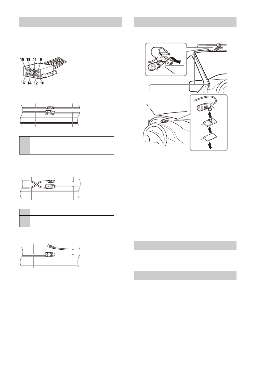
Connection
FUSE 10A
*
3
*
3
*
3
Subwoofer*
1
Power amplifier*
1
from a wired remote control (not
supplied)
*4
*6*
7
from a car antenna (aeri al)*
5
Rear view
camera*
1
*
3
Light green
Purple/white striped
For details, see “Making
connections” (page 13).
See “Power connection diagram” (page 14) for
details.
*
2
from DAB antenna (aerial)
(not supplied)*
9
Smartphone, USB device
(for audio/video
playback)*
1
*
8
• To prevent short circuits, insulate leads with a cover or tape.
• Note that the unit may be damaged if it is connected incorrectly or by short circuits.
12GB

*1 Not supplied
*8
Parking brake switch lead
Hand brake type Foot brake type
*2 Speaker impedance: 4 to 8 × 4
*3 RCA pin cord (not supplied)
*4 Depending on the type of car, use an adaptor for a wired
remote control (not supplied).
For details on using the wired remote control, see “Using
the wired remote control” (page 14).
*5 Depending on the type of car, use an adaptor (not
supplied) if the antenna (aerial) connector does not fit.
*6 Whether in use or not, route the microphone input cord
so it does not interfere with driving operations. Secure
the cord with a clamp, etc., if it is installed around your
feet.
*7 For details on installing the microphone, see “Installing
the microphone” (page 14).
*9 Set [Antenna Power] to [ON] (default) or [OFF] depending
pe of DAB antenna (aerial) (not supplied).
on the ty
Max. supply current 0.1 A
Making connections
If you have a power antenna (aerial) without a relay
box, connecting this unit with the power supply
leads may damage the antenna (aerial).
To the car’s speaker connector
To the car’s power connector
continuous power
12
supply
power antenna (aerial) /
13
power amplifier control
(REM OUT)
switched illumination
14
power supply
15 switched power supply Red
16 ground (earth) Black
Yel lo w
Blue/white striped
Orange/white
striped
To the parking brake switch lead
The m
ounting position of the parking brake
switch lead depends on your car.
Be sure to connect the parking brake lead (light
green) of the power supply leads to the
parking brake switch lead.
1
Rear speaker
(right)
2
3
Front speaker
(right)
4 Gray/black striped
5
Front speaker
(left)
6
7
Rear speaker
(left)
8
Purple
Purple/black
striped
Gray
White
White/black
striped
Green
Green/black
striped
T
o the +12 V power terminal of the car’s rear
d (only when connecting the rear
lamp lea
view camera)
Memory hold connection
When the yellow power supply lead is connected,
power will always be supplied to the memory
circuit even when the ignition switch is turned off.
Speaker connection
• Before connecting the speakers, turn the unit off.
• Use speakers with an impedance of 4 to 8 ,
and with
adequate power handling capacities to
avoid damage.
13GB
Power connection diagram
Auxiliary power connector
Red Red
Yellow Yellow
Red Red
Yellow Yellow
Red
Red
Yel l o w
Yellow
Clip (not supplied)
Check your car’s auxiliary power connector, and
match the connections of leads correctly
depending on the car.
Common connection
continuous power
12
supply
15 switched power supply Red
When the positions of the red and yellow
leads are inve
12 switched power supply Yellow
continuous power
15
supply
rted
When the car without ACC position
Yel lo w
Red
Installing the microphone
To capture your voice during handsfree calling, you
need to
install the microphone .
Cautions
•It is extremely dangerous if the cord becomes
wound around the steering column or gearstick.
Be sure to keep it and other parts from interfering
with your driving operations.
•If airbags or any other shock-absorbing
equipment
you purchased this unit or the car dealer before
installation.
Notes
• When mounting on the dashboard, remove the visor clip
carefully from the microphone , then attach the flatmount base to the microphone .
• Before attaching the double-sided tape , clean the
surface of the dashboard with a dry cloth.
are in your car, contact the store where
After matching the connections and switching
power supply leads correctly, connect the unit to
the car’s power supply. If you have any questions
and problems connecting your unit that are not
covered in this manual, consult the car dealer.
14GB
Using the wired remote control
1 To enable the wired remote control, set
[Steering Control] in [General] to [Preset].
Using the rear view camera
Installation of the re ar view camera (not suppl ied) is
required before use.
The picture from a rear view camera connected to
the C
AMERA IN terminal is displayed when:
– the back lamp of your car lights up (or the shift
lever
is set to the R (reverse) position).
– you press HOME, then touch [Rear Camera].

Installation
Face the hook
inwards.
Smartphone, USB device
(not supplied)
ɞ
ɟ
ɞ
ɟ
*
Cable cover
Release the lock of the
cable cover when
removing it.
*
*
To install the unit and the display securely, be sure
to follow the steps to in order.
Removing the trim ring and the mounting sleeve
(page 15)
B
efore mounting the unit (page 15)
Mounting the uni
Attaching
Setting up the
Makin
g sure the mounting positions of the
y (page 18)
displa
Organizing the USB cable (page 18)
Attac
hing the display to the unit (page 18)
For your safety
After mounting the display to the unit, make sure
that the display does not interfere with normal
driving operations such as blocking the driver's
view or getting the cables tangled.
Removing the trim ring and the
mounting sleeve
Before installing the unit, remove the trim ring
and the mou
1 Pinch both edges of the trim ring , then
pull it out.
t in the dashboard (page 16)
the joint cover (page 16)
display (page 16)
nting sleeve from the unit.
Before mounting the unit
Before mounting the unit in the dashboard, arrange
the USB extension cables.
USB cable connection diagram
1 Remove the cable cover, store the USB
extension cable (short) to the groove of
the unit, then attach the cable cover.
Position the USB cable so that its connector
(male) comes to the front side of the unit.
* USB connector (male)
2 Route the USB extension cable (long)
inside the dashboard, then connect the USB
cable (short) from the unit.
Position the USB cable so that its connector
(male) comes out from the center console panel.
2 Insert both release keys until they click,
and pull down the mounting sleeve , then
pull up the unit to separate.
* USB connector (male)
15GB

Mounting the unit in the dashboard
to dashboard/center console
Bracket
Bracket
Existing parts supplied
with your car
Depth
(within 20 mm
(
13
/16 in), in 3 steps)
Height
(within 60 mm
(2 3/8 in), in 7 steps)
Angle
(-10° to +10°, in 3
steps)
Pre-installed screws
ɹ
ɸ
ɹ
321
Using the mounting brackets supplied
with your car
You may not be able to install this unit in some
makes of Japanese cars. In such a case, consult your
Sony dealer.
Example
Note
To prevent malfunction, install only with the mounting
screws .
Setting up the display
The mounting positions of the display can be
adjusted.
Adjusting the depth of the display
position
Loosen the 3 pre-installed screws for depth
1
adjustment (on top and both sides).
Attaching the joint cover
1 Attach the joint cover to the mounting
base of the unit, then slide it into the unit
temporarily.
16GB
Slightly loosen the screws until you can slide the
connector bracket. Do not remove the screws
from the bracket. Doing so may damage the
parts.
2 Slide the connector bracket to decide the
appropriate depth position.
Adjustable depth: within 20 mm (13/16 in) (), in
3 steps, in 10 mm (
Bracket positions 1 to 3 for the display:
1: Slide-out position
2: Intermediate position
3: Slide-in position
13
/32 in) pitch ().

3 At the desired position, tighten the 3 screws
Pre-installed screws
ɹ
ɸ
ɹ
ɹ
ɹ
Pre-installed screws
0° (1 – A) -10° (3 – B) +10° (2 – B)
firmly to secure the connector bracket.
Tighten the screws firmly.
When you tighten a screw, be careful not to
apply too muc
the screw (the torque value should be from
1.2 N•m to 1.5 N•m).
h torque as doing so may damage
Adjusting the height of the display
position
Remove the 4 pre-installed screws for
1
height adjustment (on both sides).
2 Slide the connector bracket up or down to
decide the appropriate height position.
Adjustable height: within 60 mm (2 3/8 in) (),
in 7 steps, in 10 mm (
13
/32 in) pitch ().
Adjusting the display angle (tilt)
Remove the 2 pre-installed screws for angle
1
adjustment (on both sides).
2 Adjust the display angle to decide the
appropriate angle.
Adjustable angle: -10° to +10°, in 3 steps
Screw holes to use:
3 At the desired position, tighten the 4 screws
firmly to secure the connector bracket.
Tighten the screws firmly.
When you tighten a screw, be careful not to
apply too muc
the screw (the torque value should be from
1.2 N•m to 1.5 N•m).
h torque as doing so may damage
3 At the desired angle, tighten the 2 screws
through the screw holes (upper or lower)
that match the display angle.
Tighten the screws firmly.
When you tighten a screw, be careful not to
apply too
the screw (the torque value should be from
1.2 N•m to 1.5 N•m).
much torque as doing so may damage
17GB

Making sure the mounting positions
of the display
Be careful not to pinch your fingers or scratch the
center cluster panel of your car when attaching the
display to the unit.
1 Attach the display to the unit temporarily.
2 Confirm that the display does not block the
driver’s view or interfere with normal
driving operations.
If further adjustment of the mounting position
(depth, height, angle) is necessary, remove the
display from the unit, then adjust it again
accordingly.
Organizing the USB cable
1 Connect the USB extension cable (short)
to the USB port of the display, then route
the cable along the groove.
Attaching the display to the unit
Be careful not to pinch your fingers or scratch the
center cl
uster panel of your car when attaching the
display to the unit.
1 Attach the display to the unit.
Make sure that the connector brackets of the
display is fully inserted to the unit.
2 Tighten 4 screws (on top) to secure the
connector bracket to the unit.
Tighten the screws firmly.
When you tighten a screw, be careful not to
apply too muc
the screw (the torque value should be from
1.2 N•m to 1.5 N•m).
h torque as doing so may damage
3 Slide the joint cover out to protect the
mounting base of the display, then tighten
the fixing screw to secure the cover.
To prevent the extension cable from coming off,
be sure to route the USB cable along the groove
through the catches inside.
18GB
Tighten the screw firmly.
When you tighten a screw, be careful not to
apply too muc
the screw (the torque value should be from
1.2 N•m to 1.5 N•m).
h torque as doing so may damage

4 Attach the rear panel covers (L, R) along
Release the US B cable
from the slit of panel.
Fuse (10 A)
the guides for protection.
Fuse replacement
When replacing the fuse, be sure to
use one matching the amperage
rating stated on the original fuse.
If the fuse blows, check the power
conne
ction and replace the fuse.
If the fuse blows again after
replacement
internal malfunction. In such a case, consult your
nearest Sony dealer.
, there may be an
19GB
Avertissement
Pour votre sécurité, veuillez installer cet appareil
dans le tab
compte du fait que l’arrière de l’appareil chauffe
en cours d’utilisation.
Pour de plus amples détails, reportez-vous à la
sectio
Fabriqué en Thaïlande
La plaque signalétique reprenant la tension
d’alimentation, etc. se trouve sur le dessous du
châssis.
La validité du libellé CE se limite uniquement aux
pays où la loi l’impose, principalement les pays de
l’EEE (Espace économique européen) et la Suisse.
AVERTISSEMENT
Pour éviter les risques d’incendie et de choc,
n’exposez pas l’appareil à la pluie ou à
l’humidité.
Pour éviter les chocs électriques, n’ouvrez pas
le boîtier. Confiez les réparations à du
personnel qualifié uniquement.
Avis à l’attention des clients : les informations
uivante
s
appareils vendus dans des pays qui
appliquent les directives de l’Union
Européenne
Ce produit a été fabriqué par ou pour le compte de
Sony Corporation.
Importateur dans l’UE : Sony Europe B.V.
Les questions basées sur la législation européenne
pour l’im
produits doivent être adressées au mandataire :
Sony Belgium, bijkantoor van Sony Europe B.V., Da
Vincilaan 7-D1, 1930 Zaventem, Belgique.
Le soussigné, Sony Corporation, déclare que cet
é
quipement est c
UE.
Le texte complet de la déclaration UE de conformité
est dispo
https://compliance.sony.eu
leau de bord de la voiture en tenant
n « Raccordement/Installation » (page 10).
s s’appliquent uniquement aux
portateur ou relatives à la conformité des
onforme à la Directive 2014/53/
nible à l’adresse internet suivante :
Elimination des piles et
accumulateurs et des
équipe
ments électriques et
électroniques usagés (applicable
dans les pays de l’Union
Européenne et dans les autres
pays disposant de systèmes de
collecte sélective)
Ce symbole apposé sur le produit, la pile ou
l’accumulateur, ou sur l’emballage, indique que le
produit et les piles et accumulateurs fournis avec ce
produit ne doivent pas être traités comme de
simples déchets ménagers. Sur certains types de
piles, ce symbole apparaît parfois combiné avec un
symbole chimique. Le symbole pour le plomb (Pb)
est rajouté lorsque ces piles contiennent plus de
0,004 % de plomb. En vous assurant que les
produits, piles et accumulateurs sont mis au rebut
de façon appropriée, vous participez activement à
la prévention des conséquences négatives que leur
mauvais traitement pourrait provoquer sur
l’environnement et sur la santé humaine. Le
recyclage des matériaux contribue par ailleurs à la
préservation des ressources naturelles. Pour les
produits qui, pour des raisons de sécurité, de
performance ou d’intégrité des données,
nécessitent une connexion permanente à une pile
ou à un accumulateur intégré(e), il conviendra de
vous rapprocher d’un Service Technique qualifié
pour effectuer son remplacement. En rapportant
votre appareil électrique, les piles et accumulateurs
en fin de vie à un point de collecte approprié vous
vous assurez que le produit, la pile ou
l’accumulateur intégré sera traité correctement.
Pour tous les autres cas de figure et afin d’enlever
les piles ou accumulateurs en toute sécurité de
votre appareil, reportez-vous au manuel
d’utilisation. Rapportez les piles et accumulateurs,
et les équipements électriques et électroniques
usagés au point de collecte approprié pour le
recyclage. Pour toute information complémentaire
au sujet du recyclage de ce produit ou des piles et
accumulateurs, vous pouvez contacter votre
municipalité, votre déchetterie locale ou le point de
vente où vous avez acheté ce produit.
Avertissement si l’allumage de votre
véhicule ne possède pas de position ACC
N’installez pas cet appareil dans un véhicule qui
ne possède pas de position ACC. L’affichage de
l’appareil ne s’éteint pas même si le contact est
coupé, ce qui décharge la batterie.
2FR
Avis d’exclusion de responsabilité relatif aux
services proposés par des tiers
Les services proposés par des tiers peuvent être
modifiés, suspendus ou clôturés sans avis
préalable. Sony n’assume aucune responsabilité
dans ce genre de situation.

Remarque importante
Attention
SONY NE PEUT ÊTRE, EN AUCUN CAS, TENU POUR
RESPONSABLE D’UN QUELCONQUE DOMMAGE
ACCIDENTEL, INDIRECT OU ACCESSOIRE, OU DE
TOUT AUTRE DOMMAGE, Y COMPRIS, MAIS SANS
S’Y LIMITER, LA PERTE DE BÉNÉFICES, DE REVENUS,
DE DONNÉES, DE JOUISSANCE DU PRODUIT OU DE
TOUT ÉQUIPEMENT ASSOCIÉ, SON INDISPONIBILITÉ,
ET LE TEMPS PERDU PAR L’ACHETEUR, LIÉ À OU
RÉSULTANT DE L’UTILISATION DE CE PRODUIT, DE
SES COMPOSANTS MATÉRIELS ET/OU LOGICIELS.
Cher client, ce produit contient un émetteur radio.
Conformément au règlement UNECE n° 10, un
fabrica
nt automobile peut imposer certaines
conditions particulières pour l’installation
d’émetteurs radio dans ses véhicules.
Veuillez vérifier le manuel d’utilisation de votre
véhicu
le ou contactez le constructeur de votre
véhicule ou votre concessionnaire, avant d’installer
ce produit dans votre véhicule.
Appels d’urgence
Le système BLUETOOTH mains libres embarqué et
le dispositif électronique qui y est connecté
fonctionnent grâce aux signaux radio, aux réseaux
cellulaires et aux lignes terrestres, tout comme la
fonction de programmation par l’utilisateur. La
connexion n’est donc pas garantie en toutes
circonstances.
Par conséquent, ne vous reposez pas uniquement
s
n dispositif électronique pour vos
ur u
communications importantes (tels que les appels
médicaux d’urgence).
Communication par BLUETOOTH
Les micro-ondes émises par un dispositif
BLUETOOTH peuvent perturber le fonctionnement
des dispositifs médicaux électroniques. Dans les
circonstances qui suivent, mettez cet appareil,
ainsi que les autres dispositifs BLUETOOTH
présents, hors tension, car ils peuvent provoquer
un accident.
En présence d’un gaz inflammable, dans un
hôpital, un t
service
À proximité de portes automatiques ou d’un
syst
Cet appareil prend en charge les fonctionnalités
conf
ormes à la norme BLUETOOTH afin de fournir
une connexion sécurisée lorsque la technologie
sans fil BLUETOOTH est utilisée. Mais, en fonction
de l’environnement, la sécurité peut ne pas être
suffisante. Soyez donc prudent lorsque vous
communiquez en utilisant la technologie sans fil
BLUETOOTH.
Nous n’assumons aucune responsabilité en cas
de fuite d’informations au cours d’une
communication BLUETOOTH.
rain, un avion ou une station-
ème de détection d’incendie
Si vous avez des questions concernant cet appareil
ou si vous rencontrez des problèmes qui ne sont
pas abordés dans ce mode d’emploi, contactez
votre revendeur Sony le plus proche.
3FR

Emplacement des commandes
HOME ATTVOL VOICEOPTION
Appareil principal
La touche VOL (volume) + possède un point tactile.
Affichage/écran tactile
HOME
Affic
he l’écran HOME (page 5).
STANDBY
Maintenez enfoncé pour basculer l’appareil en
mode ve
ille (la charge USB reste disponible).
Pour reprendre, appuyez sur n’importe quelle
touche.
VOL (volume) +/–
ATT (attén ue r)
Att
Pour annuler, appuyez à nouveau ou appuyez
sur VOL +.
Maintenez enfoncé pour éteindre le moniteur.
Pour le rallumer, touchez n’importe quelle partie
de
Récepteur de la télécommande
son.
énue le
MONITOR OFF
ichage.
l’aff
4FR
OPTION
Affi
che l’écran OPTION (page 5).
/ (préc
Les fonctions varient selon la source
sélectio
– [Radio]/[DAB+] : permet de sélectionner une
station
– [USB]/[Bluetooth] : permet de passer au
fichier suivant/précédent.
Maintenez enfoncé pour :
– [Radio] : sélectionner une station
automa
– [DAB+] : sélectionner une station (lorsque
[Seek Par] est réglé sur [A-Z])/rechercher une
station (lorsque [Seek Par] est réglé sur
[Station Gp]).
– [USB]/[Bluetooth] : avancer/reculer
rapidement.
VO
ICE
Active
Apple CarP
Borne HDMI (entrée)
édent/suivant)
nnée :
mémorisée.
tiquement (SEEK+/SEEK–).
la fonction de commande vocale pour
lay et Android Auto™.

Affichages à l’écran
Écran de lecture :
Écran HOME :
Écran OPTION :
Indications d’état
S’allume quand le son est atténué.
S’allume quand AF (fréquences
alternatives) est disponible.
S’allume quand les informations de trafic
actuel (TA
disponibles.
S’allume quand une annonce DAB est
dispon
Indique l’état d’intensité du signal de la
radio DA
S’allume quand le signal Bluetooth® est
activé.
en cours d’établissement.
S’allume lorsque le périphérique audio
est lis
(Advanced Audio Distribution Profile,
profil de distribution audio avancée).
S’allume lorsqu’il est possible d’appeler
en mains
(Handsfree Profile, profil mains libres).
Indique l’état d’intensité du signal du
t
élépho
Indique l’état de charge restant de la
batter
(option de source)
Ouvre le menu d’option de source. Les éléments
dispon
ibles varient selon la source.
Zone spécifique à l’application
Affic
he des commandes de lecture/indications
ou bien l’é
varient selon la source.
Horloge
Affic
he l’heure selon le réglage défini sous Date/
Heure.
(
retour à l’écran de lecture)
Bascule entre l’écran HOME et l’écran de lecture.
: annonces routières) sont
ible.
B.
Clignote quand la connexion est
ible en activant le profil A2DP
libres en activant le profil HFP
ne mobile connecté.
ie du téléphone mobile connecté.
tat de l’appareil. Les éléments affichés
5FR

Touches de sélection des sources et réglages
Permettent de changer de source ou d’effectuer
divers ré
glages.
Cliquez pour sélectionner l’icône de réglage et
d’aut
res icônes.
Touchez l’icône de la source que vous souhaitez
sélecti
onner.
Android
Auto
DAB+ Bluetooth Tél ép ho ne
USB WebLi nk HDMI
Cam. recul Réglages
Touches de sélection du son
(EXTRA BASS)
(EQ10/Caiss. bas.)
(Monitor off)
ttent de changer le son.
Perme
Permet de modifier le réglage EXTRA BASS.
Permet de modifier le réglage EQ10/Caiss. bas.
Éteint le moniteur. Lorsque le moniteur est
ét
uchez une partie quelconque de
eint, to
l’affichage pour le rallumer.
Apple
CarPlay
Radio
Opérations de base
Pairage avec un périphérique
BLUETOOTH
Lorsque vous connectez l’appareil à un
périphérique BLUETOOTH pour la première fois, il
est nécessaire qu’ils se reconnaissent
mutuellement (c’est ce que l’on appelle le
« jumelage »). Le jumelage permet à l’appareil et à
d’
s périphériques de se reconnaître
autre
mutuellement.
1 Appuyez sur HOME, puis touchez [Réglages]
[Bluetooth] [Connexion Bluetooth]
[ACTIVÉ] [Pairage].
clignote lorsque l’appareil est en mode de
veille de jumelage.
2 Procédez au jumelage sur le périphérique
BLUETOOTH afin qu’il détecte cet appareil.
3 Sélectionnez le nom de votre modèle sur
l’affichage du périphérique BLUETOOTH*.
Une fois le jumelage effectué, reste allumé.
* Si la saisie d’une clé d’authentification est requise sur
le périphérique BLUETOOTH, saisissez [0000].
6FR
Raccordement d’une caméra de
recul
En raccordant la caméra de recul en option à la
borne CAMERA IN, vous pouvez afficher l’image de
la caméra de recul. Pour plus d’informations,
reportez-vous à la section « Raccordement/
Installation » (page 10).
Pour afficher l’image de la caméra de recul
Appuy ez sur HOME, puis touchez [Cam . recul].
Désactivation du mode de
démonstration
1 Appuyez sur HOME, puis touchez
[Réglages].
2 Touchez [Général], puis [Démo] pour le
régler sur [DÉSACTIVÉ].
3 Pour quitter le menu de configuration,
touchez deux fois (retour).

Mise à jour du firmware
Pour mettre à jour le firmware, consultez le site
d’assistance, puis suivez les instructions en ligne.
URL: https://www.sony.eu/support
Remarque
Ne retirez pas la clé USB pendant la mise à jour.
Informations complémentaires
Précautions
• L’antenne électrique se déploie
automatiquement.
• Lorsque vous revendez le véhicule contenant
l’appa
reil ou que vous le mettez au rebut,
exécutez une réinitialisation d’usine pour rétablir
tous les réglages d’origine.
• Ne renversez pas de liquide sur l’appareil.
Remarques sur la sécurité
• Respectez le code de la route, les lois et les
règlements locaux.
•Pendant la conduite
– Ne regardez pas ou n’utilisez pas l’appareil, car
cela pour
accident. Stationnez votre véhicule dans un
endroit sûr pour regarder ou utiliser l’appareil.
– N’utilisez pas la fonction de configuration ou
toute autr
votre attention de la route.
– Lorsque vous reculez le véhicule, regardez vers
l’arri
pour assurer votre sécurité, même si la caméra
de recul est raccordée. Ne vous fiez pas
exclusivement à la caméra de recul.
• Pendant l’utilisation
– N’insérez pas les mains, les doigts ou des corps
é
blesser ou endommager l’appareil.
– Maintenez les petits objets hors de portée des
enfants.
–
Veillez à attacher les ceintures de sécurité pour
éviter l
brusque du véhicule.
Prévention d’accident
Les images n’apparaissent qu’une fois que le
véhicule est stationné et que le frein de
stationnement est serré.
Si le véhicule commence à bouger pendant la
lecture vid
vous ne pouvez pas regarder la vidéo.
[Vidéo bloquée pour votre sécurité.]
rait vous distraire et provoquer un
e fonction susceptible de détourner
ère et surveillez attentivement les alentours
rs dans l’appareil, car vous pourriez vous
trange
es blessures en cas de mouvement
éo, le message suivant s’affiche et
N’utilisez pas l’appareil et ne regardez pas le
m
ur pendant la conduite.
onite
7FR

Remarques sur l’écran à cristaux liquides
• Évitez de mouiller l’écran à
cristaux liquides et ne
l’exposez pas à des liquides.
Cela pourrait provoquer un
dysfonctionnement.
•N’exercez pas de pression
excessi
ve sur l’écran à
cristaux liquides, car cela
pourrait déformer l’image ou
provoquer un dysfonctionnement (l’image
pourrait ne plus être nette ou l’écran à cristaux
liquides pourrait être endommagé).
• Ne touchez pas l’écran à cristaux liquides avec des
ob
autres que votre doigt sous peine de
jets
l’endommager ou de le briser.
• Nettoyez l’écran à cristaux liquides avec un chiffon
doux et sec. N’utilisez pas de solvants tels que de
l’essence, du diluant, des nettoyants disponibles
dans le commerce ou un produit antistatique.
•N’utilisez pas l’appareil en dehors de la plage de
températures comprises entre 0 ºC et 40 ºC.
•Si votre véhicule était stationné dans un endroit
froid ou
chaud, l’image peut ne pas être nette. Le
moniteur n’est toutefois pas endommagé et
l’image redevient nette dès que la température à
l’intérieur du véhicule est à nouveau normale.
•Certains points bleus, rouges ou verts fixes
peuvent appara
« points lumineux » et cela peut se produire sur
tout écr
liquides est un composant de précision dont plus
de 99,99 % des segments sont fonctionnels. Il est
toutefois
(généralement 0,01 %) de segments ne s’illumine
pas co
votre lecture.
ître sur le moniteur. Ces sont des
an à cristaux liquides. L’écran à cristaux
possible qu’un petit pourcentage
rrectement. Cela n’entrave toutefois pas
Remarques sur l’écran tactile
•L’appareil utilise un écran tactile résistif. Touchez
l’écran directement avec le bout du doigt.
• Cet appareil ne prend pas en charge la commande
multi-po
•Ne touchez pas l’écran avec des objets pointus
•Ne laissez aucun objet entrer en contact avec
• Comme l’écran est en verre, ne soumettez pas
• Maintenez les autres appareils électriques à l’écart
ints.
tels qu’une a
L’utilisation d’un stylet n’est pas prise en charge
par cet appareil.
l’écra
correctement en cas de contact entre l’écran et un
objet autre que le bout de votre doigt.
l’appa
une fissure ou un éclat, ne touchez pas la partie
endommagée, sous peine de vous blesser.
de l’
dysfonctionnement de l’écran tactile.
iguille, un stylo ou un ongle.
n tactile. L’appareil risque de ne pas réagir
reil à des chocs violents. Si l’écran présente
ctile. Ils pourraient provoquer un
écran ta
À propos de l’iPhone
•Modèles d’iPhone compatibles :
ne SE (2e génération), iPhone 11 Pro Max,
iPho
iPhone 11 Pro,
iPhone XS, iPhone XR, iPhone X, iPhone 8 Plus
iPhone 8, iPhone 7 Plus, iPhone 7, iPhone SE,
iPhone 6s Plus, iPhone 6s, iPhone 6 Plus,
iPhone 6, iPhone 5s
•L’utilisation du badge Made for Apple signifie
qu’un acce
spécifiquement au produit ou aux produits Apple
identifiés dans le badge, et a été certifié par le
constructeur pour satisfaire les normes de
performance d’Apple. Apple n’est pas responsable
du fonctionnement de cet appareil ni de sa
conformité avec les consignes et normes de
sécurité.
Veuillez noter que l’utilisation de cet accessoire
a
vec un produit Apple peut avoir un effet adverse
sur les performances sans fil.
iPhone 11, iPhone XS Max,
,
ssoire a été conçu pour être raccordé
Remarque sur la licence
Ce produit contient un logiciel utilisé par Sony sous
de licence conclu avec le propriétaire des
contrat
droits de copyright. Nous sommes obligés
d’annoncer le contenu du contrat aux clients selon
les exigences du propriétaire des droits de
copyright du logiciel.
Pour plus d’informations sur les licences logicielles,
v
églages] [Général] [Licences open
oir [R
source].
Si vous avez des questions concernant cet appareil
ou si vou
s rencontrez des problèmes qui ne sont
pas abordés dans ce mode d’emploi, contactez
votre revendeur Sony le plus proche.
8FR

Spécifications
Moniteur
Type d’affichage : grand moniteur couleur à
cristaux liquides
Dimensions : 22,7 cm/ 8,95 po
Système : matrice active TFT
Nombre de pixels :
1 152 000 pixels (800 × 3 (RVB) × 480)
Système couleur :
sélection automatique PAL/NTSC pour la borne
CA
Radio
DAB/DAB+
Plage de syntonisation :
174,928 MHz – 239,200 MHz
Borne d’antenne :
Connecteur d’antenne externe
FM
Plage de syntonisation : 87,5 MHz – 108,0 MHz
Sensibilité utile : 7 dBf
Rapport signal/bruit : 70 dB (mono)
Séparation à 1 kHz : 45 dB
AM
Plage de syntonisation : 531 kHz – 1 602 kHz
Sensibilité : 32 µV
Lecteur USB
Interface :
Port USB : USB (haute vitesse)
Courant maximal : 1,5 A
HDMI*
Format d’entrée : 480p, 576p, 720p
* Sortie HDMI non disponible.
Communication sans fil
Système de communication :
Norme BLUETOOTH version 3.0
Puissance :
Norme BLUETOOTH Classe de puissance 2
(+1 dBm par conduction max.)
Portée de communication maximale*
Ligne de vision d’environ 10 m
Bande de fréquences :
Bande de 2,4 GHz (2,4000 GHz - 2,4835 GHz)
Méthode de modulation : FHSS
MERA I
N
1
:
Profils BLUETOOTH compatibles*
A2DP (Advanced Audio Distribution Profile, profil
de distr
ibution audio avancée) 1.3
AVRCP (Audio Video Remote Control Profile, profil
de comm
HFP (Handsfree Profile, profil mains libres) 1.6
PBAP (Phone Book Access Profile, profil d’accès au
répert
Codecs correspondants : SBC, AAC
*1 La portée réelle varie en fonction de nombreux facteurs
tels que la présence d’obstacles entre les appareils, les
champs magnétiques autour des fours à micro-ondes,
l’électricité statique, la sensibilité de la réception, les
performances de l’antenne, le système d’exploitation, les
applications logicielles, etc.
*2 Les profils BLUETOOTH standard indiquent la finalité de
la communication BLUETOOTH entre des périphériques.
ande audio/vidéo à distance) 1.3
oire) 1.1
2
:
Amplificateur de puissance
Sorties : sorties haut-parleurs
Impédance des haut-parleurs : 4 – 8
Puissance de sortie maximale : 55 W × 4 (sous 4 )
Généralités
Alimentation requise : batterie de véhicule 12 V CC
(masse négative)
Consommation nominale : 10 A
Dimensions (maximum) :
Environ 229 mm × 136 mm × 253 mm
(l/h/p)
Dimensions de montage :
Environ 182 mm × 53 mm × 160 mm
(l/h/p)
Poids : environ 2,4 kg
Contenu de l’emballage :
Appareil principal (1)
Composants destinés à l’installation et au
r
accor
dement (1 jeu)
Adressez-vous au concessionnaire pour tout
rensei
gnement complémentaire.
La conception et les spécifications sont sujettes à
modification sans préavis.
9FR

Copyrights
La marque et les logos Bluetooth® sont des
marques déposées appartenant à Bluetooth SIG,
Inc. et toute utilisation de ces marques par Sony
Corporation est sous licence. Les autres marques
commerciales et noms commerciaux appartiennent
à leurs propriétaires respectifs.
Windows Media est une marque ou une marque
d
e de Microsoft Corporation aux Etats-Unis
éposé
et/ou dans d’autres pays.
Ce produit est protégé par des droits de propriété
i
ectuelle de Microsoft Corporation. Toute
ntell
utilisation ou diffusion de la technologie décrite
sortant du cadre de l’utilisation de ce produit est
interdite sans licence accordée par Microsoft ou
une filiale autorisée de Microsoft.
Apple et iPhone sont des marques commerciales
d’Appl
e Inc., déposées aux États-Unis et dans
d’autres pays.
Apple CarPlay est une marque commerciale
d’Appl
e Inc.
Android Auto est une marque de Google LLC.
WebLink est une marque déposée d’Abalta
Technolo
gies, Inc. aux États-Unis et une marque
commerciale dans les autres pays.
Les termes HDMI et High-Definition Multimedia
Interf
ace ainsi que le logo HDMI sont des marques
commerciales ou des marques déposées de HDMI
Licensing Administrator, Inc. aux États-Unis et dans
d’autres pays.
Toutes les autres marques commerciales
ap
iennent à leurs propriétaires respectifs.
part
Raccordement/Installation
Attention
• N’installez pas cet appareil dans un véhicule qui
ne possède pas de position ACC. L’affichage de
l’appareil ne s’éteint pas même si le contact est
coupé, ce qui décharge la batterie.
•Acheminez tous les fils de masse jusqu’à un
p
de masse commun.
oint
• Veillez à ce qu’aucun fil ne soit coincé sous une vis
ou happé pa
une glissière de siège).
•Avant d’effectuer les raccordements, coupez le
contac
• Raccordez le câble d’alimentation à l’appar
aux haut-parleurs avant de le brancher sur le
connecteur d’alimentation auxiliaire.
•Pour des raisons de sécurité, veillez à isoler avec
du ruban isola
raccordés.
•Choisissez soigneusement l’emplacement
d’instal
conduite normale.
• Évitez d’installer l’appareil dans des endroits
soumis
excessives ou à des températures élevées,
notamment les rayons directs du soleil ou la
proximité des conduites de chauffage.
•Utilisez exclusivement le matériel de fixation
fourni af
•Veillez à utiliser les câbles d’extension USB fournis.
• Selon le type de véhicule, il se peut que l’appareil
ne puis
de détails sur l’espace de montage, reportez-vous
à la section « Vérification de l’emplacement de
montage de l’appareil » (page 11).
•Pour éviter les blessures, veillez à ne pas laisser
tomber
•Lors de l’installation, veillez à ne pas vous couper
les doigts
supports et de la base de montage.
•Ne vous pincez pas les doigts lorsque vous fixez
l’écra
• N’installez pas l’appareil dans une position qui
entrave les
dans une position où le levier de vitesses heurte
l’appareil ou une position qui empêche d’enfoncer
le bouton des feux de détresse).
•Après une longue période d’utilisation, les vis qui
maintiennent l
périodiquement ces vis.
•N’apportez pas de changements ou de
modifica
dans ce manuel.
r des pièces mobiles (par exemple,
t du véhicule pour éviter les courts-circuits.
eil et
nt les extrémités libres des fils non
lation afin que l’appareil n’entrave pas la
à la poussière, à la saleté, à des vibrations
in de garantir une installation sûre.
se pas être installé correctement. Pour plus
l’écran pendant l’installation.
avec les pièces métalliques des
n à l’appareil.
opérations de conduite (notamment
’écran peuvent se desserrer. Serrez
tions à l’appareil autres que ceux décrits
10FR

Remarque sur le câble d’alimentation (jaune)
ɸ
ɹ
Surface avant de l’appa reil
(surface de référence)
Panneau du combiné
central du véh icule
Positions des trous de vis
(pour fixer l’écran et l’appareil)
22 mm 51 mm à 71 mm
ɻ
ɼ
ɺ
ɻ
Zone masquée lorsque l’écran est
incliné vers le haut ou le bas
Position de l’appareil (position de référence)
60 mm 76 mm 60 mm
Lorsque vous raccordez cet appareil conjointement avec
d’autres équipements stéréo, l’intensité nominale du circuit
du véhicule auquel l’appareil est raccordé doit être
supérieure à la somme des intensités nominales des
fusibles de chaque composant.
Remarque sur l’installation dans des véhicules
équipés d’un système Start-Stop
L’appareil peut redémarrer lorsque le moteur est démarré à
partir du système Start-Stop. Si tel est le cas, désactivez le
système Start-Stop de votre véhicule.
Remarque sur l’installation dans des véhicules
équipés d’un système de frein de stationnement
électrique
Dans les véhicules équipés de frein de stationnement
électrique, certaines fonctions (notamment le blocage de la
vidéo) peuvent ne pas fonctionner correctement.
Réglage de l’angle de fixation
Réglez l’angle de fixation afin qu’il soit inférieur à
30°.
Vérification de l’emplacement de
montage de l’appareil
Avant d’installer l’appareil, consultez
l’installateur pour obtenir des détails sur
l’installation de l’appareil et de l’écran.
•Assurez-vous que la distance entre la surface
avant (s
urface de référence) de l’appareil monté et
la surface du combiné central du véhicule est
égale ou inférieure à 22 mm. Sinon, l’appareil ne
pourra pas être installé correctement.
• Pour votre sécurité, ajustez la position de
montage de
l’appareil de façon à ne pas entraver
les opérations de conduite telles que les
opérations du levier de vitesses ou de bouton
(interrupteur).
11FR

Liste des pièces pour installation
Câble d’alimentation (1) Vis de montage
(5 × max. 9 mm) (4)
Vis d e fixation
(pour la partie joint)
(4 × 6 mm) (4)
Microphone (1) Ba se de montage à plat (1)
Adhésif double face (1) Câble d’extension USB (long)
Câble d’extension USB (court)
(1)
Encadrement de montage (1) Clés de déblocage (2)
Garniture (1) Caches de panneau arrière
(1)
Bande adhésive (1)
(gauche, droit) (2)
•Cette liste des pièces ne comprend pas tout le
contenu de l’emballage.
• L’encadrement de montage est fixé
à l’appareil
avant son expédition. Avant de monter l’appareil,
utilisez les clés de déblocage pour retirer
l’encadrement de montage de l’appareil. Pour
plus d’informations, reportez-vous à la section
« Retrait de la garniture et de l’encadrement de
mont
age » (page 16).
•Conservez les clés de déblocage , car vous
en
aurez besoin à l’avenir si vous décidez de retirer
l’appareil de votre véhicule.
Couvre-joint (1) Vis de fixation
(pour le couvre-joint)
(3 × 8 mm) (1)
12FR

Raccordement
FUSE 10A
*
3
*
3
*
3
Caisson de graves*
1
Amplificateur de puissance*
1
d’une télécommande filaire (non
fournie)
*4
*6*
7
de l’antenne du véhicule*
5
Caméra de
recul*
1
*
3
Vert c lair
Rayé violet/blanc
Pour plus d’informations,
reportez-vous à la section
« Raccordements » (page 14).
Pour plus de détails, reportez-vous à la section
« Schéma de raccordement électrique » (page 15).
*
2
de l’antenne DAB (non fournie)*
9
Smartphone,
périphérique USB (pour
lecture audio/vidéo)*
1
*
8
• Pour éviter les courts-circuits, isolez les fils à l’aide d’un cache ou de ruban isolant.
• Notez que l’appareil peut être endommagé s’il n’est pas raccordé correctement ou en cas de courtscircuits entre les fils.
13FR

*1 Non fourni
*8
Câble du contacteur de frein de s tationnement
Type frein à main Type frein à pédale
*2 Impédance des haut-parleurs : 4 à 8 × 4
*3 Cordon à broches RCA (non fourni)
*4 Selon le type de véhicule, utilisez un adaptateur pour la
télécommande filaire (non fournie).
Pour plus de détails sur l’utilisation de la télécommande
câblée, rep
télécommande filaire » (page 15).
*5 Selon le type de véhicule, utilisez un adaptateur (non
fourni) si vous ne parvenez pas à brancher le connecteur
d’antenne.
*6 Qu’il soit utilisé ou non, acheminez le cordon de l’entrée
micro de
Fixez le cordon avec un attache-câble ou autre s’il est
installé près de vos pieds.
*7 Pour plus de détails sur l’installation du micro, reportez-
vous à la section « Installation du micro » (page 15).
*9 Réglez [Puissance de l’antenne] sur [ACTIVÉ] (par défaut)
ou [DÉSACTIVÉ] selon le type d’antenne DAB (non
fournie).
Courant d’alimentation max. 0,1 A
ortez-vous à la section « Utilisation de la
façon à ce qu’il n’interfère pas avec la conduite.
Raccordements
Si vous disposez d’une antenne électrique
dépourvue de relais, vous risquez de
l’endommager si vous raccordez cet appareil à
l’aide du câble d’alimentation .
Vers le connecteur des haut-parleurs du
véhicul
e
Vers le connecteur d’alimentation du véhicule
alimentation
12
permanente
antenne électrique/
13
amplificateur de
puissance (REM OUT)
alimentation de
14
l’éclairage commutée
15 alimentation commutée Rouge
16 masse Noir
Jaune
Rayé bleu/blanc
Rayé orange/
blanc
Vers le câble du contacteur de frein de
s
onnement
tati
La position de montage du câble du contacteur
de frein de stationnement dépend de votre
véhicule.
Veillez à raccorder le câble du frein de
stationnement (vert clair) du câble
d’alimentation au câble du contacteur de
frein de stationnement.
1
Haut-parleur
arrière (droit)
2 Rayé violet/noir
3
Haut-parleur
avant (droit)
4 Rayé gris/noir
5
Haut-parleur
avant (gauche)
6 Rayé blanc/noir
7
Haut-parleur
arrière (gauche)
8 Rayé vert/noir
14FR
Violet
Gris
Blanc
Vert
Vers la borne d’alimentation +12 V du câble
des feu
x arrière du véhicule (uniquement en
cas de raccordement de la caméra de recul)
Raccordement de protection de la
mémoire
Lorsque le câble d’alimentation jaune est raccordé,
le circuit mémoire est toujours alimenté, même
lorsque le contact est coupé.
Raccordement des haut-parleurs
•Avant de raccorder les haut-parleurs, mettez
l’appareil hors tension.
•Utilisez des haut-parleurs dont l’impédance est
compri
se entre 4 et 8 et dont la puissance
admissible est appropriée pour éviter qu’ils soient
endommagés.

Schéma de raccordement électrique
Connecteur d’alimentation auxiliaire
Rouge Rouge
Jaune Jaune
Rouge Rouge
Jaune Jaune
Rouge
Rouge
Jaune
Jaune
Clip (non fourni)
Vérifiez le connecteur d’alimentation auxiliaire de
votre véhicule et faites correspondre correctement
les raccordements en fonction du véhicule.
Raccordement ordinaire
alimentation
12
permanente
15 alimentation commutée Rouge
Quand les positions des câbles rouge et
jaune son
12 alimentation commutée Jaune
15
t inversées
alimentation
permanente
Quand le véhicule est dépourvu de position
AC
C
Jaune
Rouge
Installation du micro
Pour capter votre voix lors d’un appel en mains
li
vous devez installer le microphone .
bres,
Attention
• Il est extrêmement dangereux d’avoir le cordon
enroulé autour de la colonne de direction ou du
levier de vitesses. Empêchez le cordon et d’autres
composants d’interférer avec votre conduite.
• Si des airbags ou d’autres équipements anti-chocs
se trouvent
magasin où vous avez acheté l’appareil ou le
concessionnaire avant installation.
Remarques
• En cas de montage sur le tableau de bord, retirez
délicatement l’attache du microphone , puis fixez la
base de montage à plat sur le microphone .
• Avant de placer l’adhésif double face , nettoyez la
surface du tableau de bord avec un chiffon sec.
dans votre véhicule, contactez le
Utilisation de la télécommande filaire
1 Pour activer la télécommande filaire, réglez
[Contrôle direction] sous [Général] sur
[Présélectionnée].
Après avoir fait correspondre correctement les
raccordements et les câbles d’alimentation
commutée, raccordez l’appareil à l’alimentation du
véhicule. Si vous avez des questions et si vous
rencontrez des problèmes pour le raccordement de
cet appareil qui ne sont pas abordés dans ce mode
d’emploi, contactez votre concessionnaire
automobile.
Utilisation de la caméra de recul
L’installation de la caméra de recul (non fournie) est
requise avant toute utilisation.
L’image d’une caméra de recul raccordée à la borne
CAMERA IN
– les feux de recul de votre véhicule s’allument (ou
lorsqu
(marche arrière)).
– vous appuyez sur HOME, puis touchez [Cam.
recul].
s’affiche lorsque :
e le levier de vitesse est placé en position R
15FR

Installation
Dirigez le crochet
vers l’intérieur.
Smartphone, périphérique
USB (non fourni)
ɞ
ɟ
ɞ
ɟ
*
Cache-câble
Libérez le verrou du
cache-câble lorsque
vous le retirez.
*
*
Pour installer l’appareil et l’écran en toute sécurité,
veillez à suivre les étapes à dans l’ordre.
Retrait de la garniture et de l’encadrement de
montage (p
Avant de monter l’appareil (page 16)
Monta
(page 17
Fixation du couvre-joint (page 17)
Réglag
Conf
l’écr
Acheminement du câble USB (page 19)
Fixa
Pour votre sécurité
Après avoir fixé l’écran à l’appareil, assurez-vous
que l’écran n’entrave pas les opérations de
conduite normales, notamment en obstruant la vue
du conducteur ou en provoquant un
enchevêtrement des câbles.
Retrait de la garniture et de
l’encadrement de montage
Avant d’installer l’appareil, retirez sa garniture et
son enca
1 Pincez les deux bords de la garniture ,
puis retirez-la.
age 16)
ge de l’appareil dans le tableau de bord
)
e de l’écran (page 17)
irmation des positions de montage de
an (page 19)
tion de l’écran à l’appareil (page 19)
drement de montage .
Avant de monter l’appareil
Avant de monter l’appareil dans le tableau de bord,
disposez les câbles d’extension USB.
Schéma de raccordement des câbles USB
1 Retirez le cache-câble, installez le câble
d’extension USB (court) dans la rainure
de l’appareil, puis fixez le cache-câble.
Positionnez le câble USB de façon à ce que son
connecteur (mâle) vienne vers l’avant de
l’appareil.
* Connecteur USB (mâle)
2 Acheminez le câble d’extension USB (long)
à l’intérieur du tableau de bord, puis
raccordez le câble d’extension USB (court)
à partir de l’appareil.
Positionnez le câble USB de façon à ce que son
connecteur (mâle) sorte du panneau de console
centrale.
2 Insérez les deux clés de déblocage
jusqu’à ce qu’elles émettent un déclic,
poussez l’encadrement de montage vers
le bas, puis dégagez l’appareil en le tirant
vers le haut.
16FR
* Connecteur USB (mâle)

Montage de l’appareil dans le
vers tableau de bord/console centrale
Support
Support
Pièces existantes
fournies avec votre
véhicule
Profondeur
(jusqu’à 20 mm, en
3 étapes)
Hauteur
(jusqu’à 60 mm, en
7 étapes)
Inclinaison
(-10° à +10°, en
3 étapes)
Vis pré-installées
ɹ
ɸ
ɹ
321
tableau de bord
Utilisation des supports de montage
fournis avec votre véhicule
Vous risquez de ne pas pouvoir installer cet appareil
dans certains véhicules japonais. Dans ce cas,
consultez votre revendeur Sony.
Exemple
Remarque
Pour éviter tout dysfonctionnement, installez l’appareil
uniquement avec les vis de montage .
Fixation du couvre-joint
1 Fixez le couvre-joint sur la base de
montage de l’appareil, puis glissez-le
temporairement dans l’appareil.
Réglage de l’écran
Vous pouvez ajuster les positions de montage de
l’écran.
Réglage de la profondeur de la position
de l’écran
Desserrez les 3 vis pré-installées pour régler
1
la profondeur (sur le haut et les deux côtés).
Desse rrez légèrem ent les vi s jusqu’à ce que vous
puissiez faire glisser le support du connecteur.
Ne retirez pas les vis du support. Sinon, vous
risquez d’endommager les pièces.
2 Faites glisser le support du connecteur pour
déterminer la position de profondeur
adéquate.
Profondeur ajustable : jusqu’à 20 mm (), en
3 étapes, par pas de 10 mm ().
Positions du support 1 à 3 pour l’écran :
1 : position extérieure
2 : position intermédiaire
3 : position intérieure
17FR

3 À la position désirée, serrez fermement les 3
Vis pré-installées
ɹ
ɸ
ɹ
ɹ
ɹ
Vis pré-installées
0° (1 – A) -10° (3 – B) +10° (2 – B)
vis pour fixer le support du connecteur.
Serrez les vis fermement.
Quand vous serrez une vis, veillez à ne pas
appliquer
d’endommager la vis (la valeur de couple doit
être comprise entre 1,2 N•m et 1,5 N•m).
un couple excessif, sous peine
Réglage de la hauteur de la position de
l’écran
Retirez les 4 vis pré-installées pour régler la
1
hauteur (sur les deux côtés).
2 Faites glisser le support du connecteur vers
le haut ou le bas pour déterminer la
position de hauteur adéquate.
Hauteur ajustable : jusqu’à 60 mm (), en 7
étapes, par pas de 10 mm ().
Serrez les vis fermement.
Quand vous serrez une vis, veillez à ne pas
appliqu
er un couple excessif, sous peine
d’endommager la vis (la valeur de couple doit
être comprise entre 1,2 N•m et 1,5 N•m).
Réglage de l’inclinaison de l’écran
(angle)
Retirez les 2 vis pré-installées pour régler
1
l’inclinaison (sur les deux côtés).
2 Ajustez l’inclinaison de l’écran pour décider
de la position appropriée.
Inclinaison ajustable : -10° à +10°, en 3 étapes
Trous de vis à utiliser :
3 À la position désirée, serrez fermement les
4 vis pour fixer le support du connecteur.
18FR

3 À l’inclinaison souhaitée, serrez les 2 vis
dans les trous de vis (supérieurs ou
inférieurs) qui correspondent à l’inclinaison
de l’écran.
Serrez les vis fermement.
Quand vous serrez une vis, veillez à ne pas
r un couple excessif, sous peine
applique
d’endommager la vis (la valeur de couple doit
être comprise entre 1,2 N•m et 1,5 N•m).
Pour éviter que le câble d’extension se détache,
veillez à acheminer le câble USB le long de la
rainure dans les encoches intérieures.
Fixation de l’écran à l’appareil
Veillez à ne pas vous pincer les doigts ou à griffer le
pa
nneau du co
lorsque vous fixez l’écran à l’appareil.
mbiné central de votre véhicule
1 Fixez l’écran à l’appareil.
Confirmation des positions de
montage de l’écran
Veillez à ne pas vous pincer les doigts ou à griffer le
au du combiné central de votre véhicule
panne
lorsque vous fixez l’écran à l’appareil.
1 Fixez temporairement l’écran à l’appareil.
2 Confirmez que l’écran n’entrave pas la vue
du conducteur ou les opérations de
conduite normale.
Si la position de montage (profondeur, hauteur,
inclinaison) doit être réajustée, enlevez l’écran
de l’appareil et ajustez-le à nouveau comme
requis.
Acheminement du câble USB
1 Raccordez le câble d’extension USB (court)
au port USB de l’écran, puis acheminez le
câble le long de la rainure.
Assurez-vous que les supports du connecteur de
l’écran sont insérés à fond dans l’appareil.
2 Serrez 4 vis (en haut) pour fixer le
support du connecteur à l’unité.
Serrez les vis fermement.
Quand vous serrez une vis, veillez à ne pas
appliq
uer un couple excessif, sous peine
d’endommager la vis (la valeur de couple doit
être comprise entre 1,2 N•m et 1,5 N•m).
3 Glissez le couvre-joint vers l’extérieur
pour protéger la base de montage de
l’écran, puis serrez la vis de fixation pour
fixer le couvre-joint.
Serrez la vis fermement.
Quand vous serrez une vis, veillez à ne pas
uer un couple excessif, sous peine
appliq
d’endommager la vis (la valeur de couple doit
être comprise entre 1,2 N•m et 1,5 N•m).
19FR

4 Fixez les caches de panneau arrière (G, D)
Libérez le câble USB de
l’encoche du panneau.
Fusible (10 A )
le long des guides à des fins de protection.
Remplacement du fusible
Lorsque vous remplacez le fusible,
veillez à utiliser un fusible dont
l’intensité n ominale correspond à la
valeur indiquée sur le fusible
usagé.
Si le fusible saute, vérifiez le
branc
hement de l’alimentation et
remplacez-le.
Si le nouveau fusible saute également, il est
possib
le que l’appareil soit défectueux. Dans ce cas,
consultez votre revendeur Sony le plus proche.
20FR


Warnung
Für mögliche spätere Service-Anfragen, notieren
Sie sich bitte vor der Installation Ihres Gerätes hier
die Seriennummer:
S/N: ___________________________
Hinweis: Die 7-stellige Seriennummer finden Sie
oben a
uf der Verpackung des Gerätes oder unten
auf dem Gerät selber.
Installieren Sie das Gerät aus Sicherheitsgründen
u
gt im Armaturenbrett des Fahrzeugs,
nbedin
denn die Rückseite des Geräts erwärmt sich bei
Betrieb.
Erläuterungen dazu finden Sie unter „Anschluss/
Installation“ (Seite 10).
Hergestellt in Thailand
Das Ty
penschild mit Betriebsspannung usw.
befindet sich an der Geräteunterseite.
Die Gültigkeit des CE-Zeichens beschränkt sich auf
Länder, in denen es gesetzlich vorgeschrieben ist,
hauptsächlich in Ländern des Europäischen
Wirtschaftsraums (EWR) und der Schweiz.
WARNUNG
Um Feuer oder Stromschläge zu vermeiden,
setzen Sie das Gerät weder Regen noch
Feuchtigkeit aus.
Um einen Stromschlag zu vermeiden, öffnen
Sie das Gehäuse nicht. Überlassen Sie die
Wartung nur qualifiziertem Personal.
Hinweis für Kunden: Die folgenden
mationen gelten nur für Geräte, die in
nfor
I
Ländern verkauft werden, in denen EURichtlinien gelten
Dieses Produkt wurde von oder für die Sony
Corporation hergestellt.
EU Importeur: Sony Europe B.V.
Anfragen an den Importeur oder zur
Produk
tkonformität auf Grundlage der
Gesetzgebung in Europa senden Sie bitte an den
Bevollmächtigten Sony Belgium, bijkantoor van
Sony Europe B.V., Da Vincilaan 7-D1, 1930
Zaventem, Belgien.
Hiermit erklärt Sony Corporation, dass diese
F
nlage der Richtlinie 2014/53/EU entspricht.
unka
Der vollständige Text der EU-Konformitätserklärung
ist unter
der folgenden Internetadresse verfügbar:
https://compliance.sony.eu
Entsorgung von gebrauchten
Batterien und Akkus und
gebraucht
en elektrischen und
elektronischen Geräten
(anzuwenden in den Ländern der
Europäischen Union und anderen
Ländern mit einem separaten
Sammelsystem für diese Produkte)
Das Symbol auf dem Produkt, der Batterie/dem
Akku oder der Verpackung weist darauf hin, dass
das Produkt oder die Batterie/der Akku nicht als
normaler Haushaltsabfall zu behandeln sind. Ein
zusätzliches chemisches Symbol Pb (Blei) unter der
durchgestrichenen Mülltonne bedeutet, dass die
Batterie/der Akku einen Anteil von mehr als
0,004 % Blei enthält. Durch Ihren Beitrag zum
korrekte
n Entsorgen des Produktes und der
Batterie/des Akkus schützen Sie die Umwelt und
die Gesundheit Ihrer Mitmenschen. Umwelt und
Gesundheit werden durch falsches Entsorgen
gefährdet. Materialrecycling hilft, den Verbrauch
von Rohstoffen zu verringern. Bei Produkten, die
auf Grund ihrer Sicherheit, der Funktionalität oder
als Sicherung vor Datenverlust eine ständige
Verbindung zur eingebauten Batterie/zum
eingebauten Akku benötigen, sollte die Batterie/
der Akku nur durch qualifiziertes Servicepersonal
ausgetauscht werden. Um sicherzustellen, dass das
Produkt und die Batterie/der Akku korrekt entsorgt
werden, geben Sie das Produkt zwecks Entsorgung
an einer geeigneten Annahmestelle für das
Recycling von elektrischen und elektronischen
Geräten ab. Für alle anderen Batterien/Akkus
entnehmen Sie die Batterie/den Akku bitte
entsprechend dem Kapitel über die sichere
Entfernung der Batterie/des Akkus. Geben Sie die
Batterie/den Akku an einer geeigneten
Annahmestelle für das Recycling von Batterien/
Akkus ab. Weitere Informationen über das
Recycling dieses Produkts oder der Batterie/des
Akkus erhalten Sie von Ihrer Gemeinde, den
kommunalen Entsorgungsbetrieben oder dem
Geschäft, in dem Sie das Produkt gekauft haben.
Hinweis für Lithiumbatterien: Bitte geben Sie nur
entladene Batterien an den Sammelstellen ab.
Wegen Kurzschlussgefahr überkleben Sie bitte die
Pole der Batterie mit Klebestreifen. Sie erkennen
Lithiumbatterien an den Abkürzungen Li oder CR.
Warnung bei einem Fahrzeug mit
Zündschloss ohne Zubehörposition ACC
Installieren Sie dieses Gerät nicht in einem
Fahrzeug, das keine ACC-Position hat. Das
Display des Geräts schaltet sich auch nach dem
Ausschalten der Zündung nicht aus, was zu einer
Entladung der Batterie führt.
2DE

Haftungsausschluss für von Dritten
angebotene Dienste
Von Dritten angebotene Dienste können ohne
vorherige Ankündigung geändert, ausgesetzt oder
eingestellt werden. Sony übernimmt in diesen
Fällen keine Haftung.
Wichtiger Hinweis
Vorsicht
UNTER KEINEN UMSTÄNDEN ÜBERNIMMT SONY DIE
HAFTUNG FÜR INDIREKTE, NEBEN-, FOLGE- ODER
SONSTIGE SCHÄDEN. DIESER
HAFTUNGSAUSSCHLUSS GILT OHNE JEDE
EINSCHRÄNKUNG FÜR ENTGANGENEN GEWINN,
ENTGANGENES EINKOMMEN, DATENVERLUST,
NUTZUNGSAUSFALL DES PRODUKTS ODER
ZUGEHÖRIGER GERÄTE, AUSFALLZEITEN UND
ZEITAUFWAND DES KÄUFERS, DIE AUF DIE
VERWENDUNG DIESES PRODUKTS, DER HARDWARE
UND/ODER SEINER SOFTWARE ZURÜCKGEHEN
ODER IN VERBINDUNG DAMIT AUFTRETEN.
Hinweis für den Kunden: Diese Produkt umfasst
einen Funksend
Gemäß UNECE Regelung 10 kann ein
Fahrze
Installation von Funksendern in Fahrzeugen
festlegen.
Bitte schlagen Sie in der Betriebsanleitung zum
F
ahrze
Fahrzeughersteller, bevor Sie dieses Produkt im
Fahrzeug installieren.
Notrufe
Diese BLUETOOTH-Freisprecheinrichtung für das
Auto und das elektronische Gerät, das mit der
Freisprecheinrichtung verbunden ist, arbeiten mit
Funksignalen, Mobilfunk- und Festnetzen sowie
benutzerprogrammierten Funktionen, bei denen
nicht unter allen Umständen eine Verbindung
garantiert werden kann.
Verlassen Sie sich daher bei wichtigen Mitteilungen
(
B. medizinischen Notfällen) nicht
wie z.
ausschließlich auf elektronische Geräte.
BLUETOOTH-Kommunikation
Von einem BLUETOOTH-Gerät ausgehende
Mikrowellen können den Betrieb von
elektronischen medizinischen Geräten
beeinflussen. Schalten Sie dieses Gerät und
andere BLUETOOTH-Geräte an folgenden Orten
aus. Andernfalls besteht Unfallgefahr.
A
n Orten mit entzündlichen Gasen, in einem
Krank
Tan ks tel le
In der Nähe von automatischen Türen oder
Feue
er.
ughersteller bestimmte Bedingungen für die
ug nach oder wenden Sie sich an den
enhaus, Zug, Flugzeug oder an einer
rmeldern
Dieses Gerät unterstützt dem BLUETOOTH-
Standa
rd entsprechende Sicherheitsfunktionen,
um die Verbindungssicherheit bei BLUETOOTHFunkverbindungen zu gewährleisten. Je nach
Einstellung bieten diese jedoch möglicherweise
keinen ausreichenden Schutz. Seien Sie bei der
Kommunikation mit BLUETOOTH-Funktechnologie
also vorsichtig.
F
ür Sicherheitslücken bei der Übertragung von
tionen während der BLUETOOTH-
Informa
Kommunikation kann keine Haftung
übernommen werden.
Sollten an Ihrem Gerät Probleme auftreten oder
s
en Sie Fragen haben, auf die in dieser
ollt
Anleitung nicht eingegangen wird, wenden Sie sich
bitte an Ihren Sony-Händler.
3DE

Lage und Funktion der Teile und Bedienelemente
HOME ATTVOL VOICEOPTION
Hauptgerät
Die VOL (Lautstärke) +-Taste verfügt über einen
fühlbaren Punkt.
Display/Touchscreen
HOME
Zeigt de
n HOME-Bildschirm an (Seite 5).
STANDBY
Halten Sie diese Taste gedrückt, um das Gerät in
den Standby-M
USB ist weiterhin möglich). Drücken Sie eine
beliebige Taste, um fortzufahren.
VOL (
Lautstärke) +/–
ATT (Tondämpfung)
Dämpft de
Zum Abbrechen erneut drücken oder VOL +
drücken.
MON
Halten Sie diese Taste gedrückt, um den Monitor
auszusch
Um den Monitor wieder einzuschalten, berühren
Sie einen b
Empfänger für die Fernbedienung
odus zu versetzen (Laden per
n Ton vorübergehend.
ITOR OFF
alten.
eliebigen Teil des Displays.
4DE
OPTION
/ (Zurüc
VO
HDMI-Anschluss (Eingang)
n OPTION-Bildschirm an (Seite 5).
Zeigt de
Die Funktionen variieren abhängig von der
ausgewählt
– [Tuner]/[DAB+]: Wählt einen voreingestellten
Sender
– [USB]/[Bluetooth]: Wechselt zur vorherigen/
nächsten Datei.
Drücken und halten, um:
– [Tuner]: Stellt automatisch einen Sender ein
(SEEK+/S
– [DAB+]: Auswählen eines Senders (wenn [Seek
nach] auf [A-Z] gesetzt ist)/Suchen nach
einem Sender (wenn [Seek nach] auf [SenderGp] gesetzt ist).
– [USB]/[Bluetooth]: Schneller Rücklauf/
Schneller Vorlauf.
ICE
viert die Sprachbefehlsfunktion für Apple
Akti
CarPla
y und Android Auto™.
k/Weiter)
en Quelle:
aus.
EEK–).

Bildschirmanzeigen
Wiedergabebildschirm:
HOME-Bildschirm:
OPTION-Bildschirm:
Statusanzeige
Leuchtet auf, wenn der Ton gedämpft ist.
Leuchtet auf, wenn AF
(Alternativfrequenzen) verfügbar ist.
Leuchtet auf, wenn aktuelle
Verke
hrsinformationen (TA: Traffic
Announcement) verfügbar sind.
Leuchtet auf, wenn eine DAB-Ansage
verfügbar is
Zeigt den Signalstärke-Status des DABTuners
Leuchtet auf, wenn das Bluetooth®Signal a
Verbindung hergestellt wird.
Leuchtet, wenn durch Aktivieren des
A2DP (Adv
Profile) die Wiedergabe mit dem
Audiogerät möglich ist.
Leuchtet, wenn Freisprechanrufe über
HFP (Hand
Zeigt den Signalstärkestatus des
verbundenen Mob
Zeigt die Akkurestladung des
verbundenen Mob
(Quelloption)
Zeigt das Menü „Quelloption“ an. Die
verfüg
baren Elemente unterscheiden sich je
nach Quelle.
Anwendungsspezifischer Bereich
Zeig
t Wiedergabesteuerungen/Anzeigen oder
den St
atus des Geräts an. Die angezeigten
Elemente unterscheiden sich je nach Quelle.
Uhr
Zeig
t die Uhrzeit an, die in der Einstellung
„Datum/U
(Rückkehr zum Wiedergabebildschirm)
Wechselt vom HOME-Bildschirm zum
Wiederg
abebildschirm.
t.
an.
ktiviert ist. Blinkt, wenn die
anced Audio Distribution
sfree Profile) möglich sind.
iltelefons an.
iltelefons an.
hrzeit“ eingestellt wurde.
5DE

Auswahltasten für Quellen und Einstellungen
Ändert die Quelle oder nimmt verschiedene
Einstell
ungen vor.
Streichen Sie schnell mit dem Finger darüber,
um das Ei
auszuwählen.
Berühren Sie das Quellensymbol, das Sie
auswä
Klangauswahltasten
Ändert de
(EXTRA BASS)
Ändert die EXTRA BASS-Einstellung.
(EQ10/Subwoofer)
Ändert die EQ10/Subwoofer-Einstellung.
(Monitor aus)
Schaltet den Monitor aus. Wenn der Monitor
a
Teil des Displays, um ihn wieder einzuschalten.
nstellungssymbol und andere Symbole
hlen möchten.
Android
Auto
DAB+ Bluetooth Tel ef on
USB WebLi nk HDMI
Rückf.kam. Einstell.
n Klang.
chaltet ist, berühren Sie einen beliebigen
usges
Apple
CarPlay
Tune r
Grundfunktionen
Pairing mit einem BLUETOOTHGerät
Wenn Sie zum ersten Mal eine Verbindung zu
einem BLUETOOTH-Gerät herstellen wollen, ist eine
gegenseitige Registrierung (das so genannte
„Pairing“) erforderlich. Durch das Pairing können
dieses und andere Geräte einander erkennen.
1 Drücken Sie HOME und berühren Sie dann
[Einstell.] [Bluetooth] [BluetoothVerb indun g] [EIN] [Pairing].
blinkt, wenn sich dieses Gerät im
Bereitschaftsmodus für das Pairing befindet.
2 Führen Sie das Pairing am BLUETOOTH-
Gerät durch, sodass es dieses Gerät erkennt.
3 Wählen Sie die Bezeichnung Ihres Modells
am Display des BLUETOOTH-Geräts* aus.
Nach erfolgreichem Pairing leuchtet stetig.
* Wenn am BLUETOOTH-Gerät ein Passwort eingegeben
werden muss, geben Sie [0000] ein.
6DE
Anschließen einer
Rückfahrkamera
Wenn Sie eine gesondert erhältliche
Rückfahrkamera an den Anschluss CAMERA IN
anschließen, können Sie das Bild von der
Rückfahrkamera anzeigen lassen. Erläuterungen
dazu finden Sie unter „Anschluss/Installation“
(Seite 10).
So zeigen Sie das Bild von der
Rückfahrkamera an
Drücken Sie HOME und berühren Sie dann
[Rückf.kam.].
Beenden des Demo-Modus
1 Drücken Sie HOME und berühren Sie dann
[Einstell.].
2 Berühren Sie [Allgemein] und dann [Demo],
um den Modus auf [AUS] zu setzen.
3 Um das Einstellungsmenü zu beenden,
berühren Sie zweimal (Zurück).

Aktualisieren der Firmware
Zum Aktualisieren der Firmware rufen Sie die
Support-Website auf, und gehen nach den online
angezeigten Anweisungen vor.
URL: https://www.sony.eu/support
Hinweis
Trennen Sie während der Aktualisierung nicht das USB-Gerät
vom Gerät.
Weitere Informationen
Sicherheitsmaßnahmen
• Motorantennen werden automatisch ausgefahren.
• Wenn Sie das Fahrzeug mit dem installierten Gerät
entsorg
en oder einem Dritten überlassen, setzen
Sie durch eine Initialisierung der Einstellungen alle
Werte auf die werksseitigen Einstellungen zurück.
• Achten Sie darauf, dass keine Flüssigkeiten auf
da
ät gelangen.
s Ger
Sicherheitshinweise
• Beachten Sie stets die örtlichen Verkehrsregeln
und -vorschriften.
•Während der Fahrt
– Bedienen Sie das Gerät während der Fahrt nicht
und schauen Si
könnten Sie abgelenkt werden und einen Unfall
verursachen. Wenn Sie auf das Gerät schauen
oder es bedienen wollen, parken Sie das
Fahrzeug zuvor an einer sicheren Stelle.
– Verwenden Sie die Einstellfunktionen nicht und
f
ühren Si
die Sie vom Straßenverkehr ablenken könnten.
– Schauen Sie aus Sicherheitsgründen beim
Rückw
achten Sie auf die Umgebung, und zwar auch
dann, wenn eine Rückfahrkamera
angeschlossen ist. Verlassen Sie sich nicht allein
auf die Rückfahrkamera.
• Bei der Bedienung des Geräts
– Greifen Sie nicht mit der Hand oder den Fingern
i
n das
hinein. Andernfalls kann es zu Verletzungen
oder zu Schäden am Gerät kommen.
– Bewahren Sie kleine Gegenstände außerhalb
der Reic
– Achten Sie darauf, dass alle Fahrzeuginsassen
die Sic
plötzlichen Bewegung des Fahrzeugs nicht zu
Verletzungen kommt.
Unfallverhütung
Das Bild erscheint erst, nachdem Sie das
Fahrzeug geparkt und die Parkbremse betätigt
haben.
Wenn das Fahrzeug während der
Videow
iedergabe zu fahren beginnt, erscheint
die folgende Warnmeldung und Sie können das
Video nicht anzeigen.
[Video ist zu Ihrer Sicherheit gesperrt.]
e nicht darauf. Andernfalls
e auch keine anderen Funktionen aus,
ärtsfahren unbedingt nach hinten und
Gerät und stecken Sie keine Fremdkörper
hweite von Kindern auf.
herheitsgurte anlegen, damit es bei einer
Bedienen Sie das Gerät während des Fahrens
nic
Monitor.
chauen Sie auch nicht auf den
ht und s
7DE

Hinweise zum LCD-Bildschirm
• Lassen Sie den LCDBildschirm nicht nass werden
und schützen Sie ihn vor
Flüssigkeiten. Andernfalls
kann es zu einer Fehlfunktion
kommen.
• Drücken Sie nicht zu stark auf
den L
Andernfalls kann es zu
Bildverzerrungen oder anderen Fehlfunktionen
kommen (das Bild kann verschwommen sein oder
der LCD-Bildschirm kann beschädigt werden).
• Berühren Sie den LCD-Bildschirm ausschließlich
mi
t dem
Andernfalls kann er beschädigt werden oder
zerbrechen.
• Reinigen Sie den LCD-Bildschirm mit einem
weichen, trockenen Tuch. Verwenden Sie keine
Lösungsmittel wie Benzin oder Verdünner und
keine handelsüblichen Reinigungsmittel oder
Antistatik-Sprays.
•Verwenden Sie das Gerät nicht außerhalb des
zulässigen Temperaturbereichs von 0 ºC – 40 ºC.
• Wenn Ihr Fahrzeug in sehr warmer oder sehr kalter
Umgebun
Umständen verschwommen. Der Monitor ist
jedoch nicht beschädigt und sobald sich die
Temperatur im Wageninneren normalisiert, wird
auch das Bild wieder scharf.
•Auf dem Monitor können un
rote oder grüne Punkte erscheinen. Solche so
genannten „Lichtpunkte“ können bei allen LCDBildschirmen auftreten. Der LCD-Bildschirm wird in
einer Hochpräzisionstechnologie hergestellt, so
dass über 99,99 % der Segmente korrekt
funktionieren. Ein kleiner Prozentsatz der
Segmente (in der Regel 0,01 %) leuchtet unter
Umständen jedoch nicht ordnungsgemäß. Diese
Ausfälle beeinträchtigen die Bildqualität allerdings
nicht.
chirm.
CD-Bilds
Finger und nicht mit Gegenständen.
g geparkt war, ist das Bild unter
bewegliche bla
ue,
Hinweise zum Touchscreen
•Dieses Gerät ist mit einem resistiven Touchscreen
ausgestattet. Berühren Sie den Touchscreen mit
den Fingerspitzen.
•Die Multitouch-Bedienung wird von diesem Gerät
nicht unte
• Berühren Sie den Touchscreen nicht mit harten,
scharfk
einem Stift oder den Fingernägeln. Die Bedienung
mit einem Stift wird von diesem Gerät nicht
unterstützt.
•Achten Sie darauf, dass keine Gegenstände mit
dem Touchsc
Sie den Touchscreen nicht mit dem Finger,
sondern mit einem Gegenstand berühren,
reagiert das Gerät möglicherweise nicht richtig.
rstützt.
antigen Gegenständen wie einer Nadel,
reen in Berührung kommen. Wenn
•Da der Touchscreen aus Glasmaterial besteht,
n Sie das Gerät vor starken Stößen. Bei
schütze
Rissen oder Kerben auf dem Touchscreen
berühren Sie die beschädigten Bereiche nicht.
Andernfalls kann es zu Verletzungen kommen.
•Halten Sie andere elektrische Geräte vom
Touchscr
een fern. Sie könnten Fehlfunktionen am
Touchscreen verursachen.
Informationen zum iPhone
•K
ompatible iPhone-Modelle:
ne SE (2. Generation), iPhone 11 Pro Max,
iPho
iPhone 11 Pro,
iPhone XS, iPhone XR, iPhone X, iPhone 8 Plus
iPhone 8, iPhone 7 Plus, iPhone 7, iPhone SE,
iPhone 6s Plus, iPhone 6s, iPhone 6 Plus,
iPhone 6, iPhone 5s
•Die Verwendung des „Made for Apple“-
Markenemb
speziell für den Anschluss an das(die) AppleProdukt(e) entwickelt wurde, die im
Markenemblem bezeichnet sind, und vom
Entwickler für die Erfüllung der AppleLeistungsstandards zertifiziert wurde. Apple
übernimmt keine Verantwortung für den Betrieb
dieses Geräts oder dessen Einhaltung von
Sicherheits- und gesetzlichen Standards.
Bitte beachten, dass die Verwendung dieses
Z
ubehö
Leistungsfähigkeit beeinträchtigen kann.
iPhone 11, iPhone XS Max,
,
lems bedeutet, dass ein Zubehör
rs mit einem Apple-Produkt die drahtlose
Hinweise zur Lizenz
Dieses Produkt umfasst Software, die Sony gemäß
enzvereinbarung mit dem
einer Liz
Urheberrechteinhaber verwendet. Wir sind dazu
verpflichtet, den Inhalt der Vereinbarung den
Kunden gemäß den Anforderungen des
Urheberrechteinhabers der Software bekannt zu
geben.
Informationen zu Softwarelizenzen finden Sie unter
[Einstel
l.] [Allgemein] [Open Source-Lizenzen].
Sollten an Ihrem Gerät Probleme auftreten oder
sollt
en Sie Fragen haben, auf die in dieser
Bedienungsanleitung nicht eingegangen wird,
wenden Sie sich bitte an Ihren Sony-Händler.
8DE

Technische Daten
Monitor
Display-Typ: LCD-Breitbild-Farbmonitor
Abmessungen: 22,7 cm/ 8,95 Zoll
System: TFT-Aktivmatrix
Anzahl der Pixel:
1.152.000 Pixel (800 × 3 (RGB) × 480)
Farbsystem:
PAL/NTSC mit Automatikauswahl für Anschluss
CA
Tun er
DAB/DAB+
Empfangsbereich: 174,928 MHz – 239,200 MHz
Antennenanschluss:
Anschluss für externe Antenne
FM
Empfangsbereich: 87,5 MHz – 108,0 MHz
Nutzbare Empfindlichkeit: 7 dBf
Signal-Rauschabstand: 70 dB (mono)
Kanaltrennung bei 1 kHz: 45 dB
AM
Empfangsbereich: 531 kHz – 1.602 kHz
Empfindlichkeit: 32 µV
USB-Player
Schnittstelle:
USB-Anschluss: USB (Hi-Speed)
Maximale Stromstärke: 1,5 A
HDMI*
Einga ngsfo rmat: 480 p, 576p, 720 p
* HDMI-Ausgang steht nicht zur Verfügung.
Drahtlose Kommunikation
Kommunikationssystem:
BLUETOOTH-Standard Version 3.0
Sendeleistung:
BLUETOOTH-Standard Leistungsklasse 2
(max. +1 dBm leitungsgebunden)
Maximale Kommunikationsreichweite*
Sichtlinie ca. 10 m
Frequenzbereich:
2,4-GHz-Frequenzbereich (2,4000 GHz –
2,4835 GH
Modulationsverfahren: FHSS
MERA I
N
1
:
z)
2
Kompatible BLUETOOTH-Profile*
A2DP (Advanced Audio Distribution Profile) 1.3
AVRCP (Audio Video Remote Control Profile) 1.3
HFP (Handsfree Profile) 1.6
PBAP (Phone Book Access Profile) 1.1
Entsprechender Codec: SBC, AAC
*1 Die tatsächliche Reichweite hängt von verschiedenen
Faktoren ab, wie z. B. Hindernissen zwischen Geräten,
Magnetfeldern um einen Mikrowellenherd, statischer
Elektrizität, Empfangsempfindlichkeit, Leistung der
Antenne, Betriebssystem, Softwareanwendung usw.
*2 BLUETOOTH-Standardprofile geben den Zweck der
BLUETOOTH-Kommunikation zwischen den Geräten an.
:
Endverstärker
Ausgänge: Lautsprecherausgänge
Lautsprecherimpedanz: 4 – 8
Maximale Ausgangsleistung: 55 W × 4 (an 4 )
Allgemeines
Betriebsspannung: 12 V Gleichstrom, Autobatterie
(negative Erdung)
Nennstromaufnahme: 10 A
Abmessungen (maximal):
ca. 229 mm × 136 mm × 253 mm (B/H/T)
Einbaumaße:
ca. 182 mm × 53 mm × 160 mm (B/H/T)
Gewicht: ca. 2,4 kg
Lieferumfang:
Hauptgerät (1)
Montageteile und Anschlusszubehör (1 Satz)
Nähere Informationen dazu erhalten Sie beim
Hä
ndler.
Änderungen, die dem technischen Fortschritt
dienen, bleiben vorbehalten.
9DE

Urheberrechte
Der Bluetooth® Schriftzug und die Bluetooth® Logos
sind eingetragene Markenzeichen der Bluetooth
SIG, Inc., und jegliche Verwendung dieser Marken
durch die Sony Corporation erfolgt in Lizenz.
Andere Markenzeichen und Produktnamen sind
Eigentum der jeweiligen Rechteinhaber.
Windows Media ist ein eingetragenes
M
eichen oder Markenzeichen der Microsoft
arkenz
Corporation in den USA und/oder anderen Ländern.
Dieses Produkt ist durch bestimmte gewerbliche
Sc
- und Urheberrechte der Microsoft
hutz
Corporation geschützt. Die Verwendung oder der
Vertrieb derartiger Technologie außerhalb dieses
Produkts ohne eine Lizenz von Microsoft oder einer
autorisierten Microsoft-Niederlassung ist untersagt.
Apple und iPhone sind Markenzeichen von Apple
Inc. und in den
eingetragen.
Apple CarPlay Ist ein Markenzeichen von Apple Inc.
Android Auto ist eine Marke von Google LLC.
WebLink ist in den USA ein eingetragenes
M
arkenz
in anderen Ländern ein Markenzeichen.
Die Begriffe HDMI und HDMI High-Definition
M
media Interface sowie das HDMI-Logo sind
ulti
Marken oder eingetragene Marken von HDMI
Licensing Administrator, Inc. in den Vereinigten
Staaten und anderen Ländern.
Alle anderen Marken sind Marken der jeweiligen
E
igentümer
USA und in anderen Ländern
eichen der Abalta Technologies, Inc., und
.
Anschluss/Installation
Vorsichtsmaßnahmen
•Installieren Sie dieses Gerät nicht in einem
Fahrzeug, das keine ACC-Position hat. Das Display
des Geräts schaltet sich auch nach dem
Ausschalten der Zündung nicht aus, was zu einer
Entladung der Batterie führt.
• Schließen Sie alle Masseleitungen an einen
g
nsamen Massepunkt an.
emei
•Achten Sie darauf, dass die Leitungen nicht unter
einer Sch
raube oder zwischen beweglichen Teilen,
wie z. B. in einer Sitzschiene, eingeklemmt
werden
.
•Schalten Sie, bevor Sie irgendwelche Anschlüsse
vornehmen, die Z
Kurzschlüsse zu vermeiden.
•Schließen Sie die Stromversorgungsleitungen
an di
eses Gerät und die Lautsprecher an, bevor
Sie sie an den Hilfsstromanschluss anschließen.
•Aus Sicherheitsgründen müssen alle losen, nicht
angeschl
abgeklebt werden.
•Wählen Sie den Einbauort sorgfältig so aus, dass
das Gerä
•Installieren Sie das Gerät nicht an einer Stelle, an
der es Staub
Erschütterungen oder hohen Temperaturen
ausgesetzt ist, wie z. B. in direktem Sonnenlicht
oder in der Nähe der Heizung.
•Verwenden Sie ausschließlich die mitgelieferten
Montag
eteile. Nur mit diesen Teilen lässt sich das
Gerät sicher montieren.
•Verwenden Sie unbedingt die mitgelieferten USBVerläng
erungskabel.
•Dieses Gerät kann je nach Fahrzeugtyp
möglic
herweise nicht ordnungsgemäß installiert
werden. Weitere Informationen zum Einbauraum
finden Sie unter „Sicherstellen des Einbauorts des
Geräts“ (Seite 11).
•Um Verletzungen zu vermeiden, achten Sie
darauf,
dass Sie das Display während der
Installation nicht fallen lassen.
• Achten Sie bei der Installation darauf, dass Sie sich
nicht die Fi
Halterungen und des Montagesockels schneiden.
•Klemmen Sie sich nicht die Finger, wenn Sie das
Displa
y am Gerät anbringen.
•Installieren Sie das Gerät nicht in einer Position, in
der es b
eim Fahren hinderlich ist (z B. in
Positio
nen, in denen der Schalthebel auf das
Gerät trifft oder die Warnblinkleuchte nicht
betätigt werden kann).
•Wenn Sie das Gerät längere Zeit verwenden,
besteht
die Möglichkeit, dass sich die Schrauben,
mit denen das Display befestigt ist, lösen. Ziehen
Sie diese Schrauben regelmäßig an.
ündung des Fahrzeugs aus, um
ossenen Leitungen mit Isolierband
t beim Fahren nicht hinderlich ist.
, Schmutz, übermäßigen
nger an den Metallteilen der
10DE
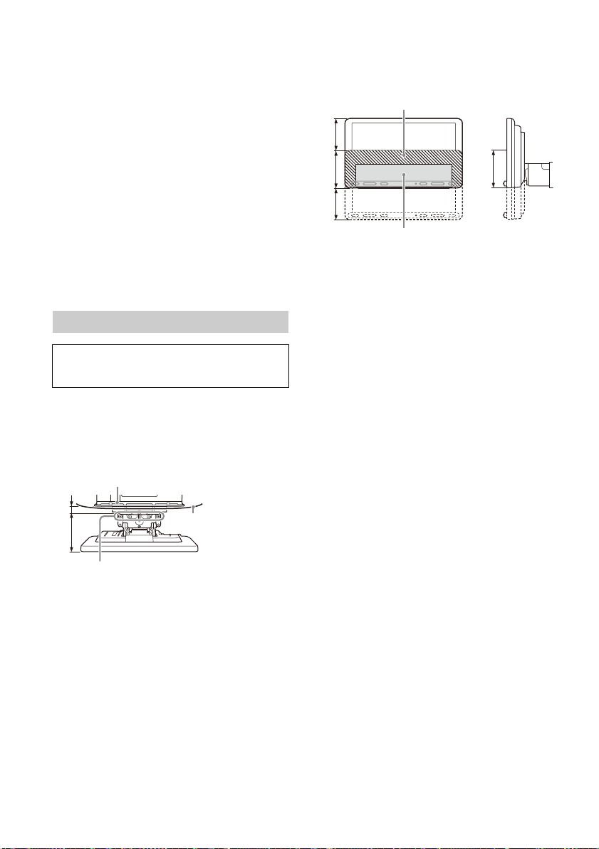
•Nehmen Sie keine anderen als die in diesem
ɸ
ɹ
Vorderfl äche des Geräts
(Referenzfläche)
Mittelkonsole Ihres
Fahrzeugs
Position der Schraubenlöcher
(zur Befestigung des Displays und des Geräts)
22 mm 51 mm bis 71 mm
ɻ
Versteckter Bereich, auch wenn das Display
nach oben oder unten verschoben wird
Position des Geräts (Referenzposition)
60 mm 76 mm 60 mm
Handbuch beschriebenen Änderungen oder
Modifikationen am Gerät vor.
Hinweis zur Stromversorgungsleitung (gelb)
Wenn Sie dieses Gerät zusammen mit anderen
Stereokomponenten anschließen, muss der Autostromkreis,
an den die Geräte angeschlossen sind, einen höheren
Ampere-Wert aufweisen als die Summe der Ampere-Werte
der Sicherungen an den einzelnen Komponenten.
Hinweis zur Installation in Fahrzeugen mit StartStopp-System
Wenn der Motor nach einem automatischen Stopp wieder
anspringt, startet dieses Gerät unter Umständen neu.
Schalten Sie in diesem Fall das Start-Stopp-System Ihres
Autos aus.
Hinweis zur Installation in Fahrzeugen mit
elektrischem Parkbremssystem
Bei Fahrzeugen mit elektrischen Parkbremsen funktionieren
einige verwandte Funktionen (z. B. die Videosperrfunktion)
mögli
cherweise nicht ordnungsgemäß.
Einstellen des Montagewinkels
Achten Sie darauf, dass der Montagewinkel
geringer ist als 30°.
Sicherstellen des Einbauorts des Geräts
Wenden Sie sich vor der Installation des Geräts an
den Installateur, um Einzelheiten zur Installation
des Geräts und des Displays zu erfahren.
•Stellen Sie sicher, dass der Abstand von der
fläche (Referenzfläche) des montierten
Vorder
Geräts zur Oberfläche der Mittelkonsole Ihres
Fahrzeugs nicht mehr als 22 mm beträgt. Bei einer
Übersch
reitung kann das Gerät nicht
ordnungsgemäß installiert werden.
• Wählen Sie zu Ihrer Sicherheit den Einbauort des
s so aus, dass das Gerät beim Fahren nicht
Gerät
hinderlich ist (z. B. Betätigung von Tasten
(Schalt
ern) oder des Schalthebels).
ɺ
ɻ
ɼ
11DE

Teileliste für die Installation
Stromversorgungsleitungen
(1)
Befestigungsschraube
(5 × max. 9 mm) (4)
Befestigungsschraube
(für das Verbundteil)
(4 × 6 mm) (4)
Mikrofon (1) Montagesockel (1)
Doppelseitiges Klebeband
(1)
USB-Verlängerungskab el
(kurz) (1)
Montagerahmen (1) Löses chlüssel (2)
Zierblende (1) Abdeckung für die
USB-Verlängerungskabel
(lang) (1)
Klebeband (1)
Geräterückseite (links/
rechts) ( 2)
•In dieser Teileliste ist nicht der gesamte Inhalt der
Packung aufgeführt.
•Der Montagerahmen wird vor
der Auslieferung
am Gerät angebracht. Vor dem Montieren des
Geräts entfernen Sie mit den Löseschlüsseln
den Montagerahmen vom Gerät. Erläuterungen
dazu finden Sie unter „ Entfernen der
Zierbl
ende und des Montagerahmens“ (Seite 16).
•Bewahren Sie die Löseschlüssel zur sp
äteren
Verwendung auf. Sie benötigen sie auch, wenn
Sie das Gerät aus dem Fahrzeug ausbauen wollen.
Verbundblech (1) Befest igungsschraube
(für das Verbundblech)
(3 × 8 mm) (1)
12DE

Anschlüsse
FUSE 10A
*
3
*
3
*
3
Tiefsttonlautsprecher*
1
Endverstärker*
1
von einer per Kabel
angeschlossenen Fernbedienung
(nicht mitgeliefert)
*4
*6*
7
von einer Autoantenne*
5
Rückfahrkamera*
1
*
3
Hellgrün
Violett/Weiß gestreift
Erläuterungen dazu finden Sie
unter „Vornehmen der
Anschlüsse“ (Seite 14).
Einzelheiten dazu finden Sie unter
„Stromanschlussdiagramm“ (Seite 15).
*
2
von DAB-Antenne (nicht
mitgeliefert)*
9
Smartphone, USB-Gerät
(für Audio-/
Videowiedergabe)*
1
*
8
• Um Kurzschlüsse zu vermeiden, isolieren Sie Leitungen mit einer Abdeckung oder einem
Isolierband.
• Beachten Sie, dass das Gerät durch inkorrekte Anschlüsse oder Kurzschlüsse an den Leitungen
beschädigt werden kann.
13DE

*1 Nicht mitgeliefert
*8
Leitung des Parkbremsschalters
Handbremse Fußbremse
*2 Lautsprecherimpedanz: 4 bis 8 × 4
*3 Cinchkabel (nicht mitgeliefert)
*4 Verwenden Sie je nach Fahrzeugtyp einen Adapter für
eine per Kabel angeschlossene Fernbedienung (nicht
mitgeliefert).
Einzelheiten zum Verwenden der Kabelfernbedienung
finden Sie unter „Verwenden der Kabelfernbedienung“
(Seite 15).
*5 Verwenden Sie je nach Fahrzeugtyp einen Adapter (nicht
mitgeliefert), wenn der Antennenanschluss nicht passt.
*6 Führen Sie das Mikrofoneingangskabel so, dass es beim
Fahren nicht hinderlich ist, unabhängig davon, ob es
gerade in Gebrauch ist oder nicht. Sichern Sie das Kabel
mit einer Kabelklemme usw., falls es durch den Fußraum
geführt werden muss.
*7 Weitere Informationen zum Installieren des Mikrofons
*9 Stellen Sie [Antennenleistung] abhängig vom DAB-
ie unter „Installieren des Mikrofons“ (Seite 15).
finden S
Antennentyp (nicht mitgeliefert) auf [EIN]
(Standardeinstellung) oder [AUS].
Max. Versorgungsstrom 0,1 A
Vornehmen der Anschlüsse
Wenn Sie eine Motorantenne ohne Relaiskästchen
verwenden und dieses Gerät mit den
Stromversorgungsleitungen anschließen, kann
die Antenne beschädigt werden.
An d
en Lautsprecheranschluss des Fahrzeugs
An den Stromanschluss des Fahrzeugs
Kontinuierli che
12
Stromversorgung
Steuerung für
Motorantenne/
13
Endverstärker (REM
OUT)
Geschaltete
14
Stromver sorgung für die
Beleuchtung
Geschaltete
15
Stromversorgung
16 Masse Schwarz
Gelb
Blau-weiß
gestreift
Orange-weiß
gestreift
Rot
Zur Leitung des Parkbremsschalters
er
Einbauort des Parkbremsschalters hängt von
D
Ihrem Fahrzeug ab.
Achten Sie darauf, dass das Kabel der
Parkbremse (hellgrün) der
Stromversorgungsleitung mit dem Kabel des
Parkbremsschalters verbunden ist.
1
Hecklautsprecher
(rechts)
2
3
Frontlautsprecher
(rechts)
4
5
Frontlautsprecher
(links)
6
7
Hecklautsprecher
(links)
8
14DE
Violett
Violett-schwarz
gestreift
Grau
Grau-schwarz
gestreift
Weiß
Weiß-s chwarz
gestreift
Grün
Grün-schwarz
gestreift
Zum +12-V-Stromanschluss des Kabels der
Heckle
uchte des Fahrzeugs (nur bei Anschluss
der Rückfahrkamera)
Anschluss für Stromversorgung des
Speichers
Wenn die gelbe Stromversorgungsleitung
angeschlossen ist, wird der Speicher stets (auch bei
ausgeschalteter Zündung) mit Strom versorgt.
Lautsprecheranschluss
• Schalten Sie das Gerät vor dem Anschließen der
Lautsprecher aus.
•Verwenden Sie Lautsprecher mit einer Impedanz
zwisc
hen 4 und 8 und mit ausreichender
Belastbarkeit, um Schäden zu vermeiden.

Stromanschlussdiagramm
Hilfsstromanschluss
Rot Rot
Gelb Gelb
Rot Rot
Gelb Gelb
Rot
Rot
Gelb
Gelb
Clip (nicht mitgeliefert)
Stellen Sie die Position des Hilfsstromanschlusses
bei Ihrem Fahrzeug fest und nehmen Sie die
Anschlüsse entsprechend dem Fahrzeug richtig vor.
Normaler Anschluss
12
15
Wenn die Position der roten und gelben
Leitun
12
15
Bei einem Fahrzeug mit Zündschloss ohne
Zubehörposition ACC
Stellen Sie die Anschlüsse her, schließen Sie die
geschalteten Stromversorgungsleitungen richtig an
und verbinden Sie dann das Gerät mit der
Stromversorgung des Fahrzeugs. Sollten beim
Anschließen des Geräts Probleme auftreten oder
sollten Sie Fragen haben, auf die in dieser
Anleitung nicht eingegangen wird, wenden Sie sich
bitte an den Fahrzeughändler.
Kontinuierliche
Stromversorgung
Geschaltete
Stromversorgung
g vertauscht ist
Geschaltete
Stromversorgung
Kontinuierliche
Stromversorgung
Installieren des Mikrofons
Damit bei Freisprechanrufen Ihre Stimme
übertrag
en werden kann, müssen Sie das Mikrofon
installieren.
Gelb
Rot
Vorsichtsmaßnahmen
• Es ist sehr gefährlich, wenn sich das Kabel um die
Lenksäule oder den Schalthebel wickelt. Achten
Sie unbedingt darauf, dass das Kabel und andere
Teile beim Fahren nicht hinderlich sind.
• Wenn Ihr Auto mit Airbags oder anderen
Aufpr
allschutzsystemen ausgestattet ist, wenden
Sie sich vor der Installation an den Händler, bei
dem Sie dieses Gerät erworben haben, oder an
den Autohändler.
Gelb
Rot
Hinweise
• Entfernen Sie bei Montage am Armaturenbrett den
Visierclip vorsichtig vom Mikrofon und befestigen Sie
dann den Montagesockel am Mikrofon .
• Reinigen Sie die Oberfläche des Armaturenbretts mit
einem trockenen Tuch, bevor Sie das doppelseitige
Klebeband anbringen.
Verwenden der Kabelfernbedienung
1 Zum Aktivieren der Kabelfernbedienung
setzen Sie [Lenkbetätigung] unter
[Allgemein] auf [Preset].
Verwenden der Rückfahrkamera
Die Rückfahrkamera (nicht mitgeliefert) muss vor
dem Gebrauch installiert werden.
Das Bild von einer an den Anschluss CAMERA IN
angeschl
ossenen Rückfahrkamera wird in
folgenden Fällen angezeigt:
15DE

– Der Rückfahrscheinwerfer des Fahrzeugs leuchtet
Der Haken muss nach
innen weisen.
Smartphone, USB-Gerät
(nicht mi tgeliefert)
ɞ
ɟ
ɞ
ɟ
*
Kabelabdeckung
Lösen Sie zum Entfernen
der Kabelabdeckung
deren Verriegelung.
(oder der Schalthebel befindet sich in der Position
R (Rückwärtsgang)).
– Sie drücken HOME und berühren dann
[Rückf.kam.].
Installation
Um das Gerät und das Display sicher zu installieren,
müssen Sie die Schritte bis in der
vorgegebenen Reihenfolge ausführen.
Entfernen der Zierblende und des
Mont
agerahmens (Seite 16)
Vor der Montage des Geräts (Seite 16)
Mont
ieren des Geräts im Armaturenbrett
(Seite
17)
Anbringen des Verbundblechs (Seite 17)
Einri
chten des Displays (Seite 17)
stellen der Einbaulage des Displays
Sicher
(Seite
19)
Verlegen des USB-Kabels (Seite 19)
Befe
stigen des Displays am Gerät (Seite 19)
Zu Ihrer Sicherheit
Stellen Sie nach dem Anbringen des Displays am
Gerät sicher, dass das Display beim Fahren nicht
hinderlich ist, etwa durch Blockieren der Sicht des
Fahrers oder durch Verfangen in den Kabeln.
2 Führen Sie die beiden Löseschlüssel ein,
bis sie mit einem Klicken einrasten. Ziehen
Sie den Montagerahmen nach unten und
das Gerät zum Herausziehen nach oben.
Vor der Montage des Geräts
Verlegen Sie vor der Montage des Geräts im
Armaturenbrett die USB-Verlängerungskabel.
USB-Kabelanschlussplan
Entfernen der Zierblende und des
Montagerahmens
Nehmen Sie vor dem Installieren des Geräts die
ende und den Montagerahmen vom
Zierbl
Gerät ab.
1 Fassen Sie die Zierblende mit den
Fingern an den Seitenkanten und ziehen Sie
sie heraus.
16DE
1 Entfernen Sie die Kabelabdeckung und
verlegen Sie das USB-Verlängerungskabel
(kurz) in der Nut des Geräts. Bringen Sie
dann die Kabelabdeckung wieder an.
Verlegen Sie das USB-Kabel so, dass sich der
Stecker an der Vorderseite des Geräts befindet.
*USB-Stecker

2 Verlegen Sie das USB-Verlängerungskabel
*
*
An Armaturenbrett/Mittelkonsole
Halterung
Halterung
Vorhandene, mit dem
Fahrzeug gelieferte
Tei le
Tiefe
(innerhalb von
20 mm, in
3 Schritten)
Höhe
(innerhalb von
60 mm, in
7 Schritten)
Winkel
(-10° bis +10°, in
3 Schritten)
Vorinstallierte Schrauben
ɹ
ɸ
ɹ
321
(lang) im Armaturenbrett und schließen
Sie dann das USB-Verlängerungskabel
(kurz) vom Gerät an.
Verlegen Sie das USB-Kabel so, dass sich der
Stecker an der Mittelkonsole befindet.
*USB-Stecker
Montieren des Geräts im
Armaturenbrett
Mittels der mit Ihrem Fahrzeug
mitgelieferten Montagehalterungen
Dieses Gerät lässt sich möglicherweise in einigen
Modellen japanischer Fahrzeughersteller nicht
einbauen. Wenden Sie sich in einem solchen Fall an
Ihren Sony-Händler.
Beispiel
Anbringen des Verbundblechs
1 Bringen Sie das Verbundblech am
Montagesockel des Geräts an und schieben
Sie es dann vorübergehend in das Gerät.
Einrichten des Displays
Die Einbaulage des Displays kann angepasst
werden.
Anpassen der Tiefe der Displayposition
Lösen Sie die 3 vorinstallierten Schrauben
1
zur Tiefenanpassung (oben und an beiden
Seiten).
Hinweis
Um Fehlfunktionen zu vermeiden, verwenden Sie zum
Einbauen des Geräts nur die Befestigungsschrauben .
Lösen Sie die Schrauben leicht, bis Sie die
Anschlusshalterung verschieben können.
Entfernen Sie nicht die Schrauben von der
Halterung. Andernfalls können die Teile
beschädigt werden.
2 Schieben Sie die Anschlusshalterung, um
die passende Tiefenposition zu bestimmen.
Einstellbare Tiefe: innerhalb von 20 mm (), in
3 Schritten, in 10-mm-Schritten ().
17DE

Halterungspositionen 1 bis 3 für das Display:
Vorinstallierte Schrauben
ɹ
ɸ
ɹ
ɹ
ɹ
Vorinstallierte Schrauben
0° (1 – A) -10° (3 – B) +10° (2 – B)
1: Auszugsposition
2: Zwischenposition
3: Einschubposition
3 Ziehen Sie die 3 Schrauben an der
gewünschten Position fest an, um die
Anschlusshalterung zu sichern.
Ziehen Sie die Schrauben fest an.
Achten Sie beim Anziehen einer Schraube
darau
f, nicht zu viel Drehmoment aufzubringen,
da dies die Schraube beschädigen kann (der
Drehmomentwert sollte zwischen 1,2 N•m und
1.5 N•m liegen).
Anpassen der Höhe der Displayposition
Lösen Sie die 4 vorinstallierten Schrauben
1
zur Höhenanpassung (an beiden Seiten).
2 Schieben Sie die Anschlusshalterung nach
oben bzw. unten, um die passende
Höhenposition zu bestimmen.
Einstellbare Höhe: innerhalb von 60 mm (), in
7 Schritten, in 10-mm-Schritten ().
3 Ziehen Sie die 4 Schrauben an der
gewünschten Position fest an, um die
Anschlusshalterung zu sichern.
Ziehen Sie die Schrauben fest an.
Achten Sie beim Anziehen einer Schraube
darauf
, nicht zu viel Drehmoment aufzubringen,
da dies die Schraube beschädigen kann (der
Drehmomentwert sollte zwischen 1,2 N•m und
1.5 N•m liegen).
Anpassen des Displaywinkels (Neigung)
Lösen Sie die 2 vorinstallierten Schrauben
1
zur Winkelanpassung (an beiden Seiten).
2 Passen Sie den Displaywinkel an, um den
passenden Winkel zu bestimmen.
Einstellbarerer Winkel -10° bis +10°, in 3 Schritten
18DE
Zu verwendende Schraubenlöcher:

3 Ziehen Sie die 2 Schrauben im gewünschten
Winkel durch die Schraubenlöcher (oben
oder unten) an, die dem Displaywinkel
entsprechen.
Ziehen Sie die Schrauben fest an.
Achten Sie beim Anziehen einer Schraube
, nicht zu viel Drehmoment aufzubringen,
darauf
da dies die Schraube beschädigen kann (der
Drehmomentwert sollte zwischen 1,2 N•m und
1.5 N•m liegen).
Verlegen des USB-Kabels
1 Schließen Sie das USB-Verlängerungskabel
(kurz) an den USB-Anschluss des Displays
an und verlegen Sie das Kabel dann in der
Nut.
Um zu verhindern, dass sich das USB-Kabel löst,
verlegen Sie es entlang der Nut durch die
inneren Verriegelungen.
Sicherstellen der Einbaulage des
Displays
Achten Sie beim Anbringen des Displays am Gerät
darauf
, sich nicht die Finger einzuklemmen oder die
Mittelkonsole Ihres Autos zu zerkratzen.
1 Befestigen Sie das Display vorübergehend
am Gerät.
2 Vergewissern Sie sich, dass das Display die
Sicht des Fahrers nicht beeinträchtigt oder
beim Fahren hinderlich ist.
Wenn weitere Einstellungen der Einbaulage
(Tiefe, Höhe, Winkel) erforderlich sind, entfernen
Sie das Display vom Gerät und stellen Sie es
entsprechend neu ein.
Befestigen des Displays am Gerät
Achten Sie beim Anbringen des Displays am Gerät
d
, sich nicht die Finger einzuklemmen oder die
arauf
Mittelkonsole Ihres Autos zu zerkratzen.
1 Befestigen Sie das Display am Gerät.
Stellen Sie sicher, dass die
Anschlusshalterungen des Displays vollständig
in das Gerät eingesetzt sind.
2 Ziehen Sie die 4 Schrauben (oben) fest,
um die Anschlusshalterung am Gerät zu
befestigen.
Ziehen Sie die Schrauben fest an.
Achten Sie beim Anziehen einer Schraube
nicht zu viel Drehmoment aufzubringen,
darauf,
da dies die Schraube beschädigen kann (der
Drehmomentwert sollte zwischen 1,2 N•m und
1.5 N•m liegen).
19DE

3 Schieben Sie das Verbundblech heraus,
Lösen Sie das USB-Kabel aus dem
Schlitz der Rückseite.
Sicherung (10 A)
um den Montagesockel des Displays zu
schützen. Ziehen Sie dann die
Befestigungsschraube , an, um die
Abdeckung zu sichern.
Ziehen Sie die Schraube fest an.
Achten Sie beim Anziehen einer Schraube
darau
f, nicht zu viel Drehmoment aufzubringen,
da dies die Schraube beschädigen kann (der
Drehmomentwert sollte zwischen 1,2 N•m und
1.5 N•m liegen).
4 Bringen Sie zum Schutz die Abdeckungen
für die Geräterückseite (L, R) entlang der
Führungen an.
Austauschen der Sicherung
Wenn Sie eine Sicherung
austauschen, achten Sie darauf,
eine Ersatzsicherung mit dem
gleichen Ampere-Wert wie die
Originalsicherung zu verwenden.
Dieser ist auf der Originalsicherung
angegeben.
Wenn die Sicherung durchbrennt, überprüfen Sie
d
omanschluss und tauschen die Sicherung
en Str
aus.
Brennt die neue Sicherung ebenfalls durch, kann
eine inte
rne Fehlfunktion vorliegen. Wenden Sie
sich in einem solchen Fall an Ihren Sony-Händler.
20DE


Advertencia
Por motivos de seguridad, asegúrese de instalar
ad en el salpicadero del automóvil, ya
esta unid
que la parte posterior de la misma se calienta
durante su uso.
Para obtener más información, consulte
“Conexión/Instalación” (página 10).
Fabricado en Tailandia
La placa de características que indica el voltaje de
funcionamiento, etc., está situada en la parte
inferior del chasis.
La validez de la marca CE está limitada a aquellos
países en los que la legislación la impone,
principalmente los países del EEE (Espacio
económico europeo) y Suiza.
ADVERTENCIA
Para evitar el riesgo de incendio o de
descarga, no exponga la unidad a la lluvia o a
la humedad.
Para evitar las descargas eléctricas, no abra el
armario. El mantenimiento solo debe ser
realizado por personal cualificado.
Aviso para los clientes: la información
e resulta de aplicación solo a los
iguient
s
equipos comercializados en países afectados
por las directivas de la UE
Este producto ha sido fabricado por, o en nombre
de Sony Corporation.
Importador UE: Sony Europe B.V.
Las consultas relacionadas con el Importador a la
UE o c
on la conformidad del producto en Europa
deben dirigirse al representante autorizado por el
fabricante, Sony Belgium, bijkantoor van Sony
Europe B.V., Da Vincilaan 7-D1, 1930 Zaventem,
Bélgica.
Por la presente, Sony Corporation declara que este
e
o es conforme con la Directiva 2014/53/UE.
quip
El texto completo de la declaración UE de
confor
midad está disponible en la dirección
Internet siguiente:
https://compliance.sony.eu
Tratamiento de las baterías y
equipos eléctricos y electrónicos al
final de
su vida útil (aplicable en la
Unión Europea y otros países con
sistemas de tratamiento selectivo
de residuos)
Este símbolo en el producto, la batería o el
embalaje indica que el producto y la batería no
pueden tratarse como un residuo doméstico
normal. En algunas baterías este símbolo puede
utilizarse en combinación con un símbolo químico.
Se añadirá el símbolo químico del plomo (Pb) si la
batería contiene más del 0,004 % de plomo. Al
asegurarse de que estos productos y baterías se
desechan correctamente, ayudará a prevenir las
posibles consecuencias negativas para la salud y el
medio ambiente que podrían derivarse de su
incorrecta manipulación. El reciclaje de los
materiales ayuda a preservar los recursos naturales.
En el caso de productos, que por razones de
seguridad, rendimiento o mantenimiento de datos,
requieran una conexión permanente con la batería
incorporada, esta batería deberá reemplazarse
únicamente por personal técnico cualificado para
ello. Para asegurarse de que la batería se desecha
correctamente, entregue estos productos al final de
su vida útil en un punto de recogida adecuado para
el reciclado de aparatos eléctricos y electrónicos.
Para el resto de baterías, consulte la sección donde
se indica cómo extraer la batería del producto de
forma segura. Deposite la batería en el
correspondiente punto de recogida para el
reciclado de baterías. Si desea obtener información
detallada sobre el reciclaje de este producto o de la
batería, póngase en contacto con el ayuntamiento,
el punto de recogida más cercano o el
establecimiento donde ha adquirido el producto o
la batería.
Advertencia en el caso de que el contacto
del coche no cuente con posición ACC
No instale la unidad en un vehículo que no
cuente con posición ACC. La pantalla de la
unidad no va a apagarse, incluso aunque apague
el contacto. Esto provocará que la carga se
descargue.
Nota legal acerca de los servicios prestados
por otros proveedores
Los servicios prestados por otros proveedores están
sujetos a cambios, anulaciones o interrupciones sin
previo aviso. Sony no asume responsabilidad
alguna en estas situaciones.
2ES

Aviso importante
Precaución
SONY NO SE HACE RESPONSABLE EN NINGÚN CASO
DE DAÑOS ACCIDENTALES, INDIRECTOS,
COLATERALES O DE OTRO TIPO, LO QUE INCLUYE, A
TÍTULO MERAMENTE ENUNCIATIVO, LA PÉRDIDA DE
BENEFICIOS, LA PÉRDIDA DE INGRESOS, LA PÉRDIDA
DE DATOS, LA IMPOSIBILIDAD DE UTILIZAR EL
PRODUCTO O EQUIPOS ASOCIADOS, EL TIEMPO DE
INACTIVIDAD O EL TIEMPO DEL COMPRADOR EN
RELACIÓN CON LA UTILIZACIÓN DE ESTE
PRODUCTO, SU HARDWARE Y/O SU SOFTWARE.
Tenga en cuenta que este producto incluye un
transmisor
Según la norma 10 de UNECE, un fabricante de un
vehículo pue
para la instalación de transmisores de radio en los
vehículos.
Consulte el manual de instrucciones de su vehículo
o póngase en co
vehículo antes de instalar este producto en su
vehículo.
Llamadas de emergencia
Este sistema manos libres para vehículo
BLUETOOTH y el dispositivo electrónico conectado
al mismo funcionan mediante señales de radio,
redes de telefonía móvil y redes terrestres, así
como a través de funciones programadas por el
usuario, por lo que la conexión no está garantizada
en todas las condiciones.
Por tanto, no confíe exclusivamente en un solo
d
isposi
importantes (como las emergencias médicas).
Acerca de la comunicación BLUETOOTH
Las microondas generadas por un dispositivo
Esta unidad es compatible con prestaciones de
No
de radio.
de imponer condiciones específicas
ntacto con el concesionario de su
tivo electrónico para las comunicaciones
BLUETOOTH pueden afectar al funcionamiento de
los dispositivos médicos electrónicos. Apague la
unidad y otros dispositivos BLUETOOTH en los
siguientes lugares, ya que podría sufrir un
accidente.
e
n lugares con presencia de gases inflamables,
un hospit
cerca de puertas automáticas o de una alarma
de ince
seguri
para proporcionar una conexión segura cuando
se utiliza la conexión inalámbrica BLUETOOTH,
pero es posible que la seguridad no sea suficiente
en función del entorno. Extreme las precauciones
al comunicarse mediante la tecnología
inalámbrica BLUETOOTH.
divulgac
comunicación BLUETOOTH.
al, un tren, un avión o una gasolinera
ndios
dad conformes con la norma BLUETOOTH
asumimos responsabilidad alguna por la
ión de información durante la
Si desea realizar alguna consulta o solucionar algún
problema
este manual, póngase en contacto con su
distribuidor Sony más cercano.
relativo a la unidad que no se trate en
3ES

Guía de elementos y controles
HOME ATTVOL VOICEOPTION
Unidad principal
El botón VOL (volumen) + cuenta con un punto
táctil.
Pantalla/pantalla táctil
HOME
Muestra
la pantalla HOME (página 5).
STANDBY
Manténgalo pulsado para activar el modo de
espera
de la unidad (la carga USB sigue estando
disponible). Para reanudar la actividad, pulse
cualquier botón.
VOL (
volumen) +/–
ATT (atenuar)
Atenúa el so
Para cancelar, pulse de nuevo o pulse VOL +.
MONITOR OFF
Mantenga pulsado para apagar el monitor.
Para volver a encenderlo, toque cualquier parte
de la panta
Receptor del mando a distancia
nido.
lla.
4ES
OPTION
Muestr
a la pantalla OPTION (página 5).
/ (ante
Funciona diferente en función de la fuente
seleccionad
– [Sintonizador]/[DAB+]: seleccione una
emisor
– [USB]/[Bluetooth]: pase al archivo anterior/
siguiente.
Mantenga pulsado para:
– [Sintonizador]: sintonizar una emisora
automá
– [DAB+]: seleccione una emisora (cuando [Seek
by] está ajustado en [A-Z])/busque una
emisora (cuando [Seek by] está ajustado en
[Estación Gp]).
– [USB]/[Bluetooth]: retroceso/avance rápido.
VO
ICE
a la función de control por voz para Apple
Activ
CarPlay y
Te rm ina l HDMI (entrad a)
rior/siguiente)
a:
a presintonizada.
ticamente (SEEK+/SEEK–).
Android Auto™.

Elementos de la pantalla
Pantalla de reproducción:
Pantalla HOME:
Pantalla OPTION:
Indicador de estado
Se ilumina cuando el sonido está
atenuado.
Se ilumina cuando está disponible AF
(frecuencias alternativas).
Se ilumina cuando está disponible la
inform
ación de tráfico actual (TA:
anuncios de tráfico).
Se ilumina cuando hay un anuncio DAB
dispon
ible.
Indica la intensidad de la señal de la
radio DA
B.
Se ilumina cuando la señal Bluetooth®
está act
ivada. Parpadea cuando la
conexión se encuentra en curso.
Se ilumina cuando se permite la
reproduc
ción en el dispositivo de audio
al habilitar el A2DP (Perfil de distribución
de audio avanzado).
Se ilumina cuando se pueden realizar
llama
das con manos libres al habilitar el
HFP (Perfil de manos libres).
Indica el estado de potencia de la señal
del telé
fono móvil conectado.
Indica el estado de batería restante del
teléfono
móvil conectado.
(opción de fuente)
Abre el menú de opción de fuente. Los
el
fuente.
Área específica de aplicación
Muest
reproduc
elementos mostrados varían en función de la
fuente.
Re
Muest
Hora.
(volv
Cambia a la pantalla HOME de la pantalla de
reprodu
disponibles varían en función de la
ementos
ra los controles/indicaciones de
ción o el estado de la unidad. Los
loj
ra la hora configurada en el ajuste Fecha/
er a la pantalla de reproducción)
cción.
5ES

Teclas de selección de fuentes y ajustes
Cambia la fuente o permite realizar varios
ajuste
s.
Desplace para seleccionar el icono de ajustes y
otros.
Toq
ue el icono de fuente que quiere seleccionar.
Android
Auto
DAB+ Bluetooth Tel éf on o
USB WebLi nk HDMI
Cám.
poster.
Teclas de selección de sonido
Cambi
a el sonido.
(EXTRA BASS)
Cambia el ajuste EXTRA BASS.
(EQ10/Altav. grav.)
Cambia el ajuste EQ10/Altav. grav.
(apagado del monitor)
Apaga el monitor. Si el monitor está apagado,
t
a activarlo.
lquier parte de la pantalla para volver
oque cua
Apple
CarPlay
Ajustes
Sintonizador
Operaciones básicas
Emparejamiento con un
dispositivo BLUETOOTH
Al conectar un dispositivo BLUETOOTH por primera
vez, debe realizar un registro compartido (llamado
“emparejamiento”). El emparejamiento permite
que esta unidad y otros dispositivos se reconozcan
mutuamente.
1 Pulse HOME y, a continuación, toque
[Ajustes] [Bluetooth] [Conexión
Bluetooth] [ACTIV.] [Conectar].
parpadea mientras la unidad está en modo
de espera de emparejamiento.
2 Realice el emparejamiento en el dispositivo
BLUETOOTH para que detecte esta unidad.
3 Seleccione el nombre de su modelo, que
aparece en la pantalla del dispositivo
BLUETOOTH*.
Cuando se realiza el emparejamiento,
permanece encendido.
* Si el dispositivo BLUETOOTH requiere una clave de
acceso, introduzca [0000].
6ES
Conexión de la cámara de visión
trasera
Al conectar la cámara de visión trasera opcional al
terminal CAMERA IN, puede mostrar la imagen de
esta. Para obtener más información, consulte
“Conexión/Instalación” (página 10).
Para mostrar la imagen de la cámara de visión
trasera
Pulse HOME y toque [Cám. poster.].
Cancelación del modo de
demostración
1 Pulse HOME y, a continuación, toque
[Ajustes].
2 Toque [General] y, a continuación,
[Demostración] para configurarlo con el
ajuste [DESAC.].
3 Para salir del menú de configuración, toque
dos veces (volver).

Actualización del firmware
Para actualizar el firmware, visite el sitio web de
soporte técnico en línea y siga las instrucciones.
URL: https://www.sony.eu/support
Nota
Durante la actualización, no desconecte el dispositivo USB.
Información adicional
Precauciones
• La antena motorizada se extiende
automáticamente.
• Si va a transferir la propiedad del vehículo o
desprend
instalada, realice un restablecimiento de los
ajustes a la configuración de fábrica.
• No derrame líquidos sobre la unidad.
Notas sobre seguridad
• Respete la normativa y legislación locales en
materia de tráfico.
• Durante la conducción
– No mire ni maneje la unidad, ya que esto podría
– No utilice la característica de configuración ni
– Al circular marcha atrás con su vehículo, mire
• Durante el funcionamiento
– No inserte sus manos, dedos u objetos externos
– Mantenga los artículos de tamaño reducido
– Asegúrese de ajustar los cinturones de
Cómo evitar un accidente
Las imágenes solo se muestran después de
estacionar el coche y activar el freno de
estacionamiento.
Si el vehículo comienza a moverse durante la
reprodu
advertencia y no podrá verlo.
[Video bloqueado para su seguridad.]
erse de este y la unidad está aún
distra
erle y provocar un accidente. Estacione su
vehículo en un lugar seguro para examinar o
manejar la unidad.
ninguna ot
carretera.
hacia atr
maniobra segura, incluso aunque la cámara
trasera esté conectada. No dependa de forma
exclusiva de la cámara de visión trasera.
e
n la un
o daños en la unidad.
aleja
segur
se produzca un movimiento repentino del
vehículo.
ra función que pueda distraerle de la
ás y alrededor para garantizar una
idad, ya que esto podría causar lesiones
dos del alcance de los niños.
idad para evitar lesiones en el caso de que
cción de vídeo, se mostrará la siguiente
No utilice la unidad ni mire el monitor mientras
co
nduce.
7ES

Notas sobre el panel LCD
•No humedezca el panel LCD
y evite que entre en contacto
con líquidos. Esto puede
provocar un funcionamiento
inadecuado.
•No presione con fuerza el
panel
LCD, ya que esto
puede distorsionar la imagen
o provocar un
funcionamiento inadecuado (la imagen podría
mostrarse de forma poco clara o el panel podría
quedar dañado).
•Toque el panel únicamente con los dedos y no
ut
ngún otro objeto, ya que podría dañar o
ilice ni
romper el panel LCD.
• Limpie el panel LCD empleando un paño suave y
seco. No utilice disolventes como bencina,
diluyentes ni productos de limpieza disponibles en
el mercado. Tampoco use un spray antiestático.
•No utilice la unidad fuera del rango de
temperaturas autorizado de 0 ºC a 40 ºC.
•Si ha estacionado su vehículo en un lugar con una
temperatu
imagen podría no ser clara. Esto no quiere decir
que el monitor esté dañado. La imagen volverá a
mostrarse correctamente cuando la temperatura
del vehículo vuelva a la normalidad.
•Existe la posibilidad de que se muestren algunos
p
monitor. A estos se les denomina “puntos
brillantes” y pueden producirse en cualquier
pantalla LCD. El panel LCD es un elemento de
precisión y su proceso de fabricación garantiza la
funcionalidad del 99,99 % de sus segmentos. Sin
e
de los segmentos (normalmente en torno al
0,01 %) no se ilumine correctamente. Esto no
interfer
vídeo.
ra muy reducida o muy elevada, la
fijos de color azul, rojo o verde en el
untos
o, es posible que un reducido porcentaje
mbarg
irá con su visualización de la imagen o el
Notas sobre la pantalla táctil
•La unidad utiliza una pantalla táctil resistivo.
Toque la pantalla directamente con el dedo.
•Esta unidad no admite los gestos multitoque.
• No toque la pantalla con objetos afilados como,
por ejempl
Esta unidad no admite el uso de un puntero.
•Evite que cualquier otro objeto entre en contacto
con la pa
contacto con un objeto que no sea su dedo, la
unidad podrá funcionar de forma incorrecta.
• La pantalla se ha fabricado con vidrio. Por ese
motivo,
producen grietas o astillado en la pantalla, no
toque la parte dañada, ya que podría sufrir
lesiones.
• Mantenga los dispositivos eléctricos alejados de la
pantal
funcionamiento inadecuado de la pantalla.
o, una aguja, un bolígrafo o las uñas.
ntalla táctil. Si la pantalla entra en
evite que sufra impactos fuertes. Si se
la táctil. Estos podrían provocar un
Acerca de la unidad iPhone
•M
odelos de iPhone compatible:
iPhone SE (2
iPhone 11 Pro,
iPhone XS, iPhone XR, iPhone X, iPhone 8 Plus
iPhone 8, iPhone 7 Plus, iPhone 7, iPhone SE,
iPhone 6s Plus, iPhone 6s, iPhone 6 Plus,
iPhone 6 y iPhone 5s
• El uso de la insignia Made for Apple significa que
un acces
específicamente al producto o a los productos
Apple identificados en la insignia, y ha sido
certificado por el fabricante de que cumple las
normas de rendimiento de Apple. Apple no se
hace responsable por el funcionamiento de este
dispositivo o su cumplimiento con normas de
seguridad y regulatorias.
Tenga en cuenta que el uso de este accesorio con
un p
inalámbrico.
.ª generación), iPhone 11 Pro Max,
iPhone 11, iPhone XS Max,
,
orio ha sido diseñado para conectarse
roducto Apple puede afectar el rendimiento
Aviso sobre licencias
Este producto contiene software utilizado por Sony
en el marco de un ac
propietario de sus derechos de autor. Estamos
obligados a compartir los contenidos del acuerdo
con los clientes según lo establecido por el
propietario de los derechos de autor del software.
Para obtener más información sobre las licencias
d
ware, seleccione [Ajustes] [General]
el soft
[Fuente para abrir licencias].
Si tiene alguna pregunta o problema relacionado
con la unida
instrucciones de funcionamiento, póngase en
contacto con su distribuidor Sony más cercano.
uerdo de licencia con el
d que no de describe en estas
8ES

Especificaciones
Sección del monitor
Tipo de pantalla: pantalla a color ancha LCD
Dimensiones: 22,7 cm/ 8,95 pulgadas
Sistema: matriz activa TFT
Número de píxeles:
1.152.000 píxeles (800 × 3 (RGB) × 480)
Sistema de color:
Selección automática PAL/NTSC para la terminal
CA
Sección de la radio
DAB/DAB+
Rango de sintonización:
174,928 MHz - 239,200 MHz
Terminal de antena:
Conector de antena externa
FM
Rango de sintonización: 87,5 Mhz - 108,0 Mhz
Sensibilidad: 7 dBf
Relación señal-ruido: 70 dB (mono)
Separación a 1 kHz: 45 dB
AM
Rango de sintonización: 531 kHz - 1.602 kHz
Sensibilidad: 32 µV
Sección del reproductor USB
Interfaz:
Puerto USB: USB (alta velocidad)
Corriente máxima: 1,5 A
Sección HDMI*
Formato de entrada: 480p, 576p, 720p
* Salida HDMI no disponible.
Comunicación inalámbrica
Sistema de comunicación:
Versión estándar 3.0 BLUETOOTH
Salida:
Norma BLUETOOTH, clase de potencia 2
(Conducción máx. +1 dBm)
Rango máximo de comunicación*
Línea de visión aprox. 10 m
Banda de frecuencia:
Banda de 2,4 GHz (2,4000 GHz - 2,4835 GHz)
Método de modulación: FHSS
MERA I
N
1
:
Perfiles BLUETOOTH compatibles*
A2DP (perfil avanzado de distribución de audio)
1.3
AVRCP (perfil de control remoto de audio/vídeo)
1.3
HFP (perfil de manos libres) 1.6
PBAP (Perfil de acceso a agenda telefónica) 1.1
Códec correspondiente: SBC, AAC
*1 La cobertura real variará en función de factores como los
obstáculos entre dispositivos, los campos magnéticos
alrededor de un horno microondas, la electricidad
estática, la sensibilidad de la recepción, el rendimiento
de la antena, el sistema operativo, la aplicación del
software, etc.
*2 Los perfiles estándar de BLUETOOTH indican la finalidad
de la comu
nicación BLUETOOTH entre dispositivos.
2
:
Sección del amplificador de potencia
Salidas: salidas de altavoz
Impedancia de altavoz: 4 – 8
Salida de potencia máxima: 55 W × 4 (a 4 )
General
Requisitos de alimentación: batería para vehículo
de 12 V CC (masa negativa)
Consumo de corriente nominal: 10 A
Dimensiones (máximo):
Aproximadamente 229 mm × 136 mm × 253 mm
(ancho/alto/fondo)
Dimensiones de montaje:
Aproximadamente 182 mm × 53 mm × 160 mm
(ancho/alto/fondo)
Peso: aproximadamente 2,4 kg
Contenidos del paquete:
Unidad principal (1)
Componentes de instalación y conexiones
(1 juego)
Para obtener más información, consulte al
di
stribu
idor.
El diseño y las especificaciones pueden variar sin
previo aviso.
9ES

Derechos de autor
Los logos y la palabra Bluetooth® son marcas
comerciales registradas de Bluetooth SIG, Inc., y
cualquier uso de esas marcas por Sony Corporation
se hace bajo licencia. Las otras marcas comerciales
y nombres de marcas pertenecen a sus respectivos
propietarios.
Windows Media es una marca comercial o marca
c
al registrada de Microsoft Corporation en
omerci
los Estados Unidos y en otros países.
Este producto está protegido por determinados
d
s de propiedad intelectual de Microsoft
erecho
Corporation. Queda prohibido el uso o distribución
de esta tecnología fuera de este producto sin las
licencias correspondientes de Microsoft o una filial
autorizada de Microsoft.
Apple y iPhone son marcas comerciales de Apple
Inc. re
gistradas en Estados Unidos y otros países.
Apple CarPlay es una marca comercial de Apple Inc.
Android Auto es una marca registrada de Google
LL
C.
ink es una marca comercial registrada de
WebL
Abalta
Technologies, Inc. en EE. UU. y una marca
comercial en los demás países.
Los términos HDMI y HDMI High-Definition
M
dia Interface, y el Logotipo HDMI son
ultime
comerciales o marcas registradas de HDMI
marcas
Licens
ing Administrator, Inc. en los Estados Unidos
y en otr
os países.
El resto de marcas comerciales pertenecen a sus
respect
ivos propietarios.
Conexión/Instalación
Precauciones
•No instale la unidad en un vehículo que no cuente
con posición ACC. La pantalla de la unidad no va a
apagarse, incluso aunque apague el contacto.
Esto provocará que la carga se descargue.
• Dirija todos los cables de masa a un punto de
mas
•Evite que los cables queden atrapados bajo un
torni
asientos).
•Antes de establecer conexiones, apague el motor
del au
•Conecte los cables de alimentación a la un
y los altavoces antes de conectarlos al conector de
alimentación auxiliar.
•Asegúrese de aislar los cables no conectados
suelto
•Elija cuidadosamente el lugar de instalación para
que la unida
conducción normales.
•Evite instalar la unidad en zonas expuestas a
polvo,
temperaturas elevadas, como la luz solar directa o
cerca de conductos de calefacción.
•Use solo el equipo de montaje suministrado para
real
izar u
•Asegúrese de utilizar los cables alargadores USB
sumin
•Es posible que esta unidad no pueda instalarse
correcta
Para obtener más información sobre el espacio de
montaje, consulte “Selección de la ubicación de
montaje de la unidad” (página 11).
•Para evitar lesiones, evite que la pantalla sufra
caídas dur
•Durante la instalación, proceda con precaución
para ev
piezas de metal de la base de montaje y de los
soportes.
•Tenga cuidado para evitar pellizcarse los dedos al
conecta
•No instale la unidad en una posición en la que
pueda i
conducción (por ejemplo, en posiciones en las
que la palanca de cambios golpee la unidad o en
las que no sea posible pulsar el botón de las luces
de emergencia).
•Al utilizar la unidad durante un periodo de tiempo
pr
olonga
los tornillos que mantienen la pantalla en
posición. Apriete estos tornillos de forma
periódica.
• No realice ningún cambio o modificación en la
unida
.
a común
llo o en piezas móviles (p. ej., rieles de
tomóvil para evitar cortocircuitos.
s con cinta aislante para mayor seguridad.
d no interfiera con las operaciones de
suciedad, vibración excesiva o
na instalación segura.
istrados.
mente, en función del tipo de vehículo.
ante la instalación.
itar cortes en los dedos causados por las
r la pantalla a la unidad.
nterferir con las operaciones de
do, existe la posibilidad de que se aflojen
d distinto a los descritos en este manual.
idad
10ES

Nota sobre el cable de alimentación (amarillo)
ɸ
ɹ
Superficie frontal de la unidad
(superficie de referencia)
Panel central de su
vehículo
Posiciones de los orificios para los tornillos
(para fijación de la pantalla y de la unidad)
22 mm 51 mm a 71 mm
ɻ
ɼ
ɺ
ɻ
Área oculta cuando la pantalla se
desliza hacia arrib a o hacia abajo
Posición de la unidad (posición de referencia)
60 mm 76 mm 60 mm
Al conectar esta unidad junto con otros componentes
estéreo, el valor del amperaje del circuito del vehículo al que
está conectada la unidad debe ser superior a la suma del
valor del amperaje del fusible de cada componente.
Nota sobre la instalación en vehículos con sistema de
arranque y parada
Al volver a poner en marcha el motor después de la
activación del sistema de arranque y parada, es posible que
la unidad se reinicie. En este caso, desactive el sistema de
arranque y parada de su vehículo.
Nota sobre la instalación en vehículos con sistema de
freno de estacionamiento eléctrico
En el caso de vehículos con frenos de estacionamiento
eléctricos, algunas características (como, por ejemplo, la de
bloqueo de vídeo) podrían no funcionar correctamente.
Ajuste del ángulo de montaje
Ajuste el ángulo de montaje a menos de 30°.
Selección de la ubicación de montaje de
la unidad
Antes de instalar la unidad, consulte a un
profesional para obtener más información sobre
el montaje de la unidad y la pantalla.
•Asegúrese de que la distancia entre la superficie
l (superficie de referencia) de la unidad
fronta
montada y la superficie de la sección central del
vehículo es de 22 mm. Si se supera este valor, la
unidad no podrá
instalarse correctamente.
• Por motivos de seguridad, debe ajustar la
ubicaci
ón de montaje de la unidad de forma que
no interfiera con las operaciones de conducción
como, por ejemplo, el uso de botones o el manejo
de la palanca de cambios.
11ES
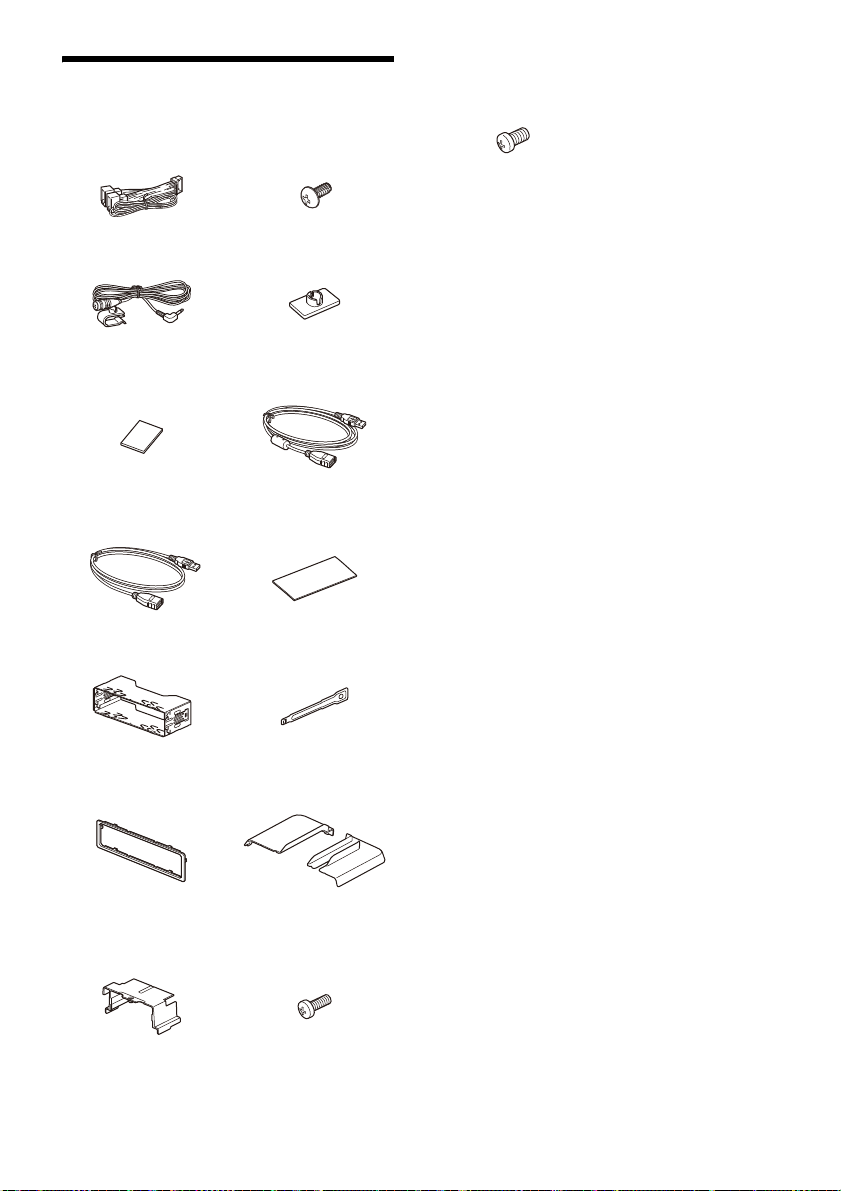
Lista de piezas para la
instalación
Cables de alimentación (1) Tornillo de montaje
Micrófono (1) Base de montaj e plana (1)
Cinta de doble cara (1) Cable alargador USB (largo)
(5 × máx. 9 mm) (4)
(1)
Tornillo de fijación
(para la pieza común)
(4 × 6 mm) (4)
•Esta lista de piezas no incluye todo el contenido
del paquete.
•El soporte de montaje está mo
ntado en la
unidad al salir de fábrica. Antes de montar la
unidad, utilice las llaves de desbloqueo para
desmontar el soporte de montaje de la unidad.
Para obtener más información, consulte “
Retirada del marco decorativo y del soporte de
montaje” (página 16).
• Guarde las llaves de desbloqueo pa
ra ut
ilizarlas
más adelante, ya que también son necesarias
para desmontar la unidad del vehículo.
Cable alargador USB (corto)
(1)
Soporte de montaje (1) L laves de desbloqueo (2)
Ma rco dec orativ o (1) Tapa del panel trasero
Tapa para junta (1) Tornillo de fijación
Cinta adhesiva (1)
(izquierda/derecha) (2)
(para el cubrejuntas)
(3 × 8 mm) (1)
12ES

Conexión
FUSE 10A
*
3
*
3
*
3
Subwoofer*
1
Amplificador de potencia*
1
desde un control remoto con cable
(no suministrado)
*4
*6*
7
desde la antena (aérea) de un
vehículo*
5
Cámara de
visión trasera*
1
*
3
Verde cl aro
A ray as mora das/b lanca s
Para obtener más información,
consulte “Establecimiento de
conexiones” (página 14).
Consulte “Diagrama de conexión de la alimentación”
(página 15) para obtener información más detallada.
*
2
desde antena (aérea) DAB
(no incluida)*
9
Smartphone, dispositivo
USB (para reproducción
de audio y vídeo)*
1
*
8
• Para evitar cortocircuitos, aísle los cables con un recubrimiento o cinta aislante.
• La unidad puede resultar dañada si se conecta de forma incorrecta o en caso de cortocircuitos en
los cables.
13ES

*1 No suministrado
*8
Cable del interruptor del
freno de estacionamiento
Tipo palanca Tipo pedal
*2 Impedancia de altavoz: de 4 a 8 × 4
*3 Cable con clavija RCA (no suministrado)
*4 En función del tipo de vehículo, use un adaptador para
un control remoto con cable (no suministrado).
Para obtener información detallada sobre el uso del
remoto con cable, consulte “Uso del control
control
remoto con cable” (página 15).
*5 En función del tipo de vehículo, use un adaptador (no
suministrado) si el conector de la antena no encaja.
*6 Tanto si se utili za como si no, procure que el recorrido del
cable
de entrada del micrófono no interfiera con las
operaciones de conducción. Fije el cable con una
abrazadera, etc., si lo instala alrededor de los pies.
*7 Para obtener más información sobre la instalación del
ono, consulte “Instalación del micrófono”
micróf
(página 15).
*9 Configure [Potencia de la antena] con la opción [ACTIV.]
(pred
eterminada) o [DESAC.] en función del tipo de
antena (aérea) DAB (no suministrado).
Corriente de alimentación máxima 0,1 A
Establecimiento de conexiones
Si tiene una antena motorizada sin caja de relés, la
conexión de esta unidad con los cables de
alimentación puede dañar la antena.
Al conector del altavoz del vehículo
Al conector de alimentación del vehículo
Fuente de alimentación
12
continua
Control de la antena
motorizada/
13
amplificador de
potencia (REM OUT)
Fuente de alimentación
14
de iluminación
conmutada
Fuente de alimentación
15
conmutada
16 Masa Negro
Amarillo
A rayas azules/
blancas
A rayas naranja/
blancas
Rojo
Al cable del interruptor del freno de
taci
onamiento
es
La posición de montaje del cable del interruptor
del freno de estacionamiento varía en cada
vehículo.
Asegúrese de conectar el cable del freno de
estacionamiento (verde claro) de los cables de
alimentación al cable del interruptor del freno
de estacionamiento.
1
Altavoz trasero
(derecho)
2
3
Altavoz delantero
(derecho)
4
5
Altavoz delantero
(izquierdo)
6
7
Altavoz trasero
(izquierdo)
8
14ES
Morado
A rayas moradas/
negras
Gris
A rayas grises/
negras
Blanco
A rayas blancas/
negras
Verde
A rayas verdes/
negras
A
l terminal de alimentación de +12 V del cable
aro trasero del vehículo (solo al conectar
del f
la cámara de visión trasera)
Conexión del soporte de la memoria
Si el cable de alimentación amarillo está conectado,
siempre se suministrará alimentación eléctrica al
circuito de memoria aunque esté apagado el
interruptor de la llave de encendido.
Conexión del altavoz
•Antes de conectar los altavoces, apague la
unidad.
• Utilice unos altavoces con una impedancia de 4
a 8 y c
on una capacidad de administración de la
potencia suficiente para evitar daños.

Diagrama de conexión de la
Conector de alimentación auxiliar
Rojo Rojo
Amarillo Amarillo
Rojo Rojo
Amarillo Amarillo
Rojo
Rojo
Amarillo
Amarillo
Gancho (no suministrado)
alimentación
Compruebe el conector de alimentación auxiliar de
su vehículo y conecte los cables correctamente en
función del vehículo.
Conexión común
Fuente de alimentación
12
continua
Fuente de alimentación
15
conmutada
Posiciones de los cables rojo y amarillo
invertidas
Fuente de alimentación
12
conmutada
Fuente de alimentación
15
continua
ra los vehículos sin posición ACC
Pa
Después de establecer las conexiones y cambiar los
cables de alimentación correctamente, conecte la
unidad a la fuente de alimentación del vehículo. Si
desea realizar alguna consulta o solucionar algún
problema relativo a la unidad que no se trate en
este manual, póngase en contacto con el
concesionario del vehículo.
Instalación del micrófono
Para capturar su voz durante llamadas manos
debe instalar el micrófono .
libres,
Amarillo
Rojo
Precauciones
• Es extremadamente peligroso que el cable se
enrolle alrededor de la columna de dirección o la
palanca de cambios. Asegúrese de que ni este ni
otros elementos no interfieran en sus operaciones
de conducción del vehículo.
• Si su automóvil cuenta con airbags o cualquier
otro equ
ipo de amortiguación de impactos,
póngase en contacto con la tienda en la que
adquirió esta unidad o con el concesionario del
automóvil antes de realizar la instalación.
Notas
Amarillo
Rojo
• Si el montaje se realiza en el salpicadero, retire
cuidadosamente la pinza para el visor del micrófono y,
a continuación, fije la base de montaje plana al
micrófono .
• Antes de fijar la cinta de doble cara , limpie la superficie
del salpicadero con un paño seco.
Uso del control remoto con cable
1 Para activar el control remoto con cable,
ajuste [Ctrl. en el volante] de [General] en
[Predefinida].
Cómo usar la cámara de visión trasera
Antes de poder utilizarla, es necesario instalar la
cámara de visión trasera (no suministrado).
La imagen de la cámara de visión trasera conectada
al term
inal CAMERA IN se muestra cuando:
– se enciende el foro de marcha atrás (o cuando la
palanca de
cambios se fija en la posición R
(marcha atrás)).
15ES

– al pulsar HOME y tocar a continuación [Cám.
Gancho mirando
hacia dentro.
Smartphone, dispositivo
USB (no suministrado)
ɞ
ɟ
ɞ
ɟ
*
Funda del cable
Retire el bloqueo d e la
funda del cable al
retirarlo .
*
*
poster.].
Instalación
Para instalar la unidad y la pantalla de forma
segura, asegúrese de seguir los pasos a en
orden.
Retirada del marco decorativo y del soporte de
montaje (p
Antes del montaje de la unidad (página 16)
Mont
(pági
Colocación de la tapa para junta (página 17)
Ajuste
Ajuste
pantal
Disposición del cable USB (página 19)
Conex
Para su seguridad
Tras montar la pantalla de la unidad, asegúrese de
que esta no interfiere con las operaciones de
conducción (por ejemplo, no bloquea la visión del
conductor ni los cables quedan enredados).
Retirada del marco decorativo y del
soporte de montaje
Antes de instalar la unidad retire el marco
decorat
unidad.
1 Sujete los dos bordes del marco decorativo
y extráigalo.
ágina 16)
aje de la unidad en el salpicadero
na 17)
de la pantalla (página 17)
de las posiciones de montaje de la
la (página 19)
ión de la pantalla a la unidad (página 19)
ivo y el soporte de montaje de la
Antes del montaje de la unidad
Antes de montar la unidad en el salpicadero,
disponga los cables alargadores USB.
Diagrama de conexiones de los cables USB
1 Retire la funda del cable, coloque el cable
alargador USB (corto) en la ranura de la
unidad y, a continuación, conecte la funda
del cable.
Sitúe el cable de USB de forma que su conector
(macho) apunte hacia el lado frontal de la
unidad.
* Conector USB (macho)
2 Disponga el cable alargador USB (largo)
en el interior del salpicadero y, a
continuación, conecte el cable alargador
USB (corto) procedente de la unidad.
Sitúe el cable de USB de forma que su conector
(macho) apunte hacia el panel de la consola
central.
2 Introduzca las dos llaves de desbloqueo
hasta que encajen, baje el soporte de
montaje y tire de la unidad hacia arriba
para separarla.
16ES
* Conector USB (macho)

Montaje de la unidad en el
al salpicadero/consola central
Soporte
Soporte
Piezas existentes
suministradas con su
vehículo
Fondo
(hasta 20 mm, en
3 pasos)
Altura
(hasta 60 mm, en
7 pasos)
Ángulo
(-10° a +10°, en
3 pasos)
Tornillos preinstalados
ɹ
ɸ
ɹ
321
salpicadero
Cómo utilizar los soportes de montaje
suministrados con su vehículo
Tal vez no pueda instalar esta unidad en algunas
marcas de vehículos japoneses. En ese caso,
consulte al distribuidor Sony.
Ejemplo
Nota
Para evitar fallos, realice la instalación solo con los tornillos
de montaje .
Ajuste de la pantalla
Puede ajustar las posiciones de montaje de la
pantalla.
Ajuste de la profundidad de la posición
de la pantalla
Afloje los 3 tornillos preinstalados para
1
ajustar la profundidad (en el lado posterior
y en los laterales).
Colocación de la tapa para junta
1 Coloque la tapa para junta en la base de
montaje de la unidad y deslícela hacia la
unidad temporalmente.
Afloje ligeramente los tornillos hasta que pueda
deslizar el soporte del conector. No retire los
tornillos del soporte. Si lo hace, podría dañar las
piezas.
2 Deslice el soporte del conector para
determinar la profundidad adecuada.
Profundidad ajustable: hasta 20 mm (), en
3 pasos, en un paso de 10 mm ().
Posiciones del soporte de 1 a 3 para la pantalla:
1: Posición extendida
2: Posición intermedia
3: Posición replegada
17ES

3 Una vez que esté en la posición deseada,
Tornillos preinstalados
ɹ
ɸ
ɹ
ɹ
ɹ
Tornillos preinstalados
0° (1 – A) -10° (3 – B) +10° (2 – B)
apriete los 3 tornillos con firmeza para
asegurar el soporte del conector.
Apriete los tornillos con firmeza.
Al apretar el tornillo, asegúrese de no aplicar un
par de
apriete excesivo, con el fin de evitar
daños en este (el valor debería estar entre
1,2 N•m y 1,5 N•m).
Ajuste de la altura de la posición de la
pantalla
Retire los 4 tornillos preinstalados para
1
ajustar la altura (en los dos lados).
Al apretar el tornillo, asegúrese de no aplicar un
apriete excesivo, con el fin de evitar
par de
daños en este (el valor debería estar entre
1,2 N•m y 1,5 N•m).
Ajuste del ángulo de la pantalla
(inclinación)
Retire los 2 tornillos preinstalados para
1
ajustar la altura (en los dos lados).
2 Ajuste el ángulo de la pantalla para
determinar cuál es el adecuado.
Ángulo ajustable: -10° a +10°, en 3 pasos
2 Deslice el soporte del conector hacia arriba
o hacia abajo para determinar la altura
adecuada.
Altura ajustable: hasta 60 mm (), en 7 pasos,
en un paso de 10 mm ().
3 Una vez que esté en la posición deseada,
apriete los 4 tornillos con firmeza para
asegurar el soporte del conector.
Apriete los tornillos con firmeza.
18ES
Orificios para tornillos:
3 Una vez que cuente con el ángulo deseado,
apriete los 2 tornillos a través de los orificios
para tornillos (superiores o inferiores) que
coincidan con el ángulo de la pantalla.

Apriete los tornillos con firmeza.
Al apretar el tornillo, asegúrese de no aplicar un
par de
apriete excesivo, con el fin de evitar
daños en este (el valor debería estar entre
1,2 N•m y 1,5 N•m).
Ajuste de las posiciones de montaje
de la pantalla
Actúe con precaución para evitar que sus dedos
n atrapados o arañar el panel central del
quede
vehículo al colocar la pantalla en la unidad.
1 Conecte la pantalla a la unidad de forma
temporal.
2 Confirme que la pantalla no bloquea la
visión del conductor ni que afecta a las
operaciones de conducción.
Si tiene que realizar ajustes adicionales de la
posición de montaje (profundidad, altura,
ángulo), retire la pantalla de la unidad y ajústela
de nuevo según sea necesario.
Disposición del cable USB
1 Conecte el cable alargador USB (corto) al
puerto USB de la pantalla y colóquelo a
continuación a lo largo de la ranura.
Conexión de la pantalla a la unidad
Actúe con precaución para evitar que sus dedos
queden at
vehículo al colocar la pantalla en la unidad.
rapados o arañar el panel central del
1 Conecte la pantalla a la unidad.
Asegúrese de que los soportes del conector de
la pantalla están insertados por completo en la
unidad.
2 Apriete los 4 tornillos (en la parte
superior) para asegurar el soporte del
conector a la unidad.
Apriete los tornillos con firmeza.
Al apretar el tornillo, asegúrese de no aplicar un
par de a
priete excesivo, con el fin de evitar
daños en este (el valor debería estar entre
1,2 N•m y 1,5 N•m).
3 Deslice la tapa para junta hacia fuera
para proteger la base de montaje de la
pantalla. A continuación, apriete el tornillo
de fijación para asegurar la tapa.
Para evitar que el cable alargador USB se salga,
asegúrese de que quede fijado dentro de la
ranura.
Apriete el tornillo con firmeza.
Al apretar el tornillo, asegúrese de no aplicar un
par de a
priete excesivo, con el fin de evitar
daños en este (el valor debería estar entre
1,2 N•m y 1,5 N•m).
19ES

4 Coloque las tapas de los paneles traseros (I,
Libere el cable USB de la
rendija del panel.
Fusible (10 A)
D) a lo largo de las guías para garantizar
la protección.
Sustitución de fusibles
Cuando sustituya el fusible,
asegúrese de usar uno que
coincida con el valor del amperaje
indicado en el fusible original.
Si se funde el fusible, compruebe la
conex
ión de la alimentación y
sustituya el fusible.
Si se vuelve a fundir el fusible después de
susti
tuirlo, puede que haya una avería interna. En
ese caso, consulte al distribuidor Sony más cercano.
20ES


Waarschuwing
Voor uw eigen veiligheid moet u dit apparaat in
het dashbo
aangezien de achterkant ervan tijdens het
gebruik erg warm wordt.
Zie "Verbinding/installatie" (pagina 11) voor meer
informatie.
Geproduceerd in Thailand
Het naamplaatje met de werkspanning enz. bevindt
zich onder aan de behuizing.
De CE-markering geldt alleen in landen waar deze
wettelijk van kracht is. Dit is met name het geval in
landen die deel uitmaken van de EER (Europese
Economische Ruimte) en Zwitserland.
WAARSCHUWING
Stel het toestel niet bloot aan regen of vocht
om brand en elektrische schokken te
vermijden.
Open de behuizing niet om elektrische
schokken te vermijden. Het toestel mag
alleen door erkende technici onderhouden
worden.
Opmerking voor klanten: de volgende
nforma
i
verkocht in landen waar de EU-richtlijnen van
kracht zijn
Dit product werd vervaardigd door of in opdracht
van Sony Corporation.
EU importeur: Sony Europe B.V.
Vragen aan de EU invoerder of met betrekking tot
Europese
gericht aan de gemachtigde vertegenwoordiger,
Sony Belgium, bijkantoor van Sony Europe B.V., Da
Vincilaan 7-D1, 1930 Zaventem, België.
Hierbij verklaart Sony Corporation dat deze
radioa
2014/53/EU.
De volledige tekst van de EUconformi
op het volgende internetadres:
https://compliance.sony.eu
ard van de auto installeren,
tie geldt enkel voor apparatuur
productconformiteit kunnen worden
pparatuur conform is met Richtlijn
teitsverklaring kan worden geraadpleegd
Verwijdering van oude batterijen,
elektrische en elektronische
appar
aten (van toepassing in de
Europese Unie en andere landen
met afzonderlijke
inzamelingssystemen)
Dit symbool op het product, de batterij of op de
verpakking wijst erop dat het product en de batterij,
niet als huishoudelijk afval behandeld mogen
worden. Op sommige batterijen kan dit symbool
gebruikt worden in combinatie met een chemisch
symbool. Het chemisch symbool voor lood (Pb)
wordt toegevoegd wanneer de batterij meer dan
0,004% lood bevat. Door deze producten en
batterijen op juiste wijze af te voeren, vermijdt u
mogelijke negatieve gevolgen voor mens en milieu
die zijn gekoppeld aan verkeerde afvalbehandeling.
Het recyclen van materialen draagt bij aan het
behoud van natuurlijke bronnen. In het geval dat de
producten om redenen van veiligheid, prestaties
dan wel in verband met data-integriteit een
permanente verbinding met een ingebouwde
batterij vereisen, mag deze batterij enkel door
gekwalificeerd servicepersoneel worden
vervangen. Om ervoor te zorgen dat de batterij,
elektrische en elektronische apparaten op een
juiste wijze zal worden behandeld, dienen deze
producten aan het eind van hun levenscyclus
worden ingeleverd bij het juiste inzamelingspunt
voor het recyclen van elektrisch en elektronisch
materiaal. Voor alle andere batterijen verwijzen we
u naar het hoofdstuk over het veilig verwijderen
van batterijen. Lever de batterijen in bij het juiste
inzamelingspunt voor het recyclen van batterijen.
Voor meer informatie over het recyclen van dit
product of de batterij, kunt u contact opnemen met
de gemeentelijke instanties, de organisatie belast
met de verwijdering van huishoudelijk afval of de
winkel waar u het product of batterij hebt gekocht.
Waarschuwing als het contactslot van de
auto geen ACC-positie heeft
Installeer dit toestel niet in een auto die geen
ACC-positie heeft. Doet u dat wel, dan zal het
scherm van het toestel zelfs na het uitzetten van
de motor niet uitschakelen, waardoor de batterij
leeg zal raken.
Disclaimer betreffende diensten
aangeboden door derden
Diensten die aangeboden worden door derden
kunnen gewijzigd, opgeschort of beëindigd
worden zonder voorafgaande kennisgeving. Sony
draagt geen enkele verantwoordelijkheid voor
dergelijke situaties.
2NL

Belangrijk bericht
Opgelet
ONDER GEEN ENKELE OMSTANDIGHEID ZAL SONY
AANSPRAKELIJK ZIJN VOOR INCIDENTELE,
INDIRECTE OF BIJKOMENDE SCHADE OF ANDERE
SCHADE WAARONDER, ZONDER BEPERKING,
VERLIES VAN WINST, INKOMSTENDERVING, VERLIES
VAN GEGEVENS, VERLIES VAN GEBRUIK VAN HET
PRODUCT OF EVENTUELE BIJKOMENDE
APPARATUUR, UITVALTIJD EN TIJD VAN DE KOPER
DIE VERBAND HOUDT MET OF ONTSTAAT UIT HET
GEBRUIK VAN DIT PRODUCT, DE BIJBEHORENDE
HARDWARE EN/OF SOFTWARE.
Geachte klant, dit product bevat een radiozender.
Volgens UNECE-reglement nr. 10 kunnen
fabri
kanten van voertuigen specifieke voorwaarden
opleggen voor het installeren van radiozenders in
voertuigen.
Gelieve de bedieningshandleiding van uw voertuig
te contro
leren of contact op te nemen met de
fabrikant van uw voertuig voordat u dit product in
uw voertuig installeert.
Noodoproepen
Dit handenvrije BLUETOOTH-toestel en het
elektronische toestel dat ermee verbonden is,
gebruiken radiosignalen, mobiele en vaste
netwerken en ook een door de gebruiker
geprogrammeerde functie. Verbinding kan niet
onder alle omstandigheden worden gegarandeerd.
Vertrouw daarom niet uitsluitend op uw
e
ronische toestel voor het tot stand brengen
lekt
van essentiële communicatie (zoals bij medische
noodgevallen).
Over BLUETOOTH-communicatie
Microgolven die worden uitgestraald door een
BLUETOOTH-apparaat kunnen de werking van
elektronische medische apparaten beïnvloeden.
Schakel dit apparaat en andere BLUETOOTHtoestellen uit op de volgende plaatsen, omdat dit
ongelukken kan veroorzaken.
w
aar brandbaar gas aanwezig is, in een
ziekenhuis
in de buurt van automatische deuren of een
branda
Dit apparaat ondersteunt
veilighe
BLUETOOTH-standaard voor een veiligere
verbinding wanneer de draadloze BLUETOOTHtechnologie wordt gebruikt, maar deze
beveiliging zal afhankelijk van de
omstandigheden mogelijk niet voldoende zijn.
Wees voorzichtig wanneer u communiceert via
draadloze BLUETOOTH-technologie.
Wi
j zijn niet verantwoordelijk voor het lekken van
informatie tijdens BLUETOOTH-communicatie.
, trein, vliegtuig of benzinestation
larm
idsvoorzieningen die voldoen aan de
Met alle vragen of problemen over dit apparaat die
bod komen in deze gebruiksaanwijzing,
niet aan
kunt u terecht bij uw Sony-leverancier.
3NL

Gids over onderdelen en bedieningselementen
HOME ATTVOL VOICEOPTION
Hoofdapparaat
De knop VOL (volume) + is voorzien van een
voelstip.
Scherm/aanraakscherm
HOME
Hiermee k
(pagina 5).
Houd deze knop ingedrukt om de stand-bystand
van het
steeds beschikbaar). Druk op een willekeurige
knop om verder te gaan.
VOL (
ATT (dempen)
Hiermee kunt
Druk nogmaals op deze knop of druk op VOL +
om te annul
Houd deze knop ingedrukt om het scherm uit te
schake
Raak het scherm op een willekeurige plaats aan
om het weer i
Ontvanger voor de afstandsbediening
unt u het HOME-scherm openen
STANDBY
toestel te activeren (laden via USB is nog
volume) +/–
u het geluid dempen.
eren.
MONITOR OFF
len.
n te schakelen.
4NL
OPTION
Hiermee kunt u het OPTION-scherm openen
(pagina 5).
/ (vorige/
Werkt verschillend afhankelijk van de
gesel
ecteerde bron:
– [Radio]/[DAB+]: hiermee kunt u een
voorgepr
– [USB]/[Bluetooth]: hiermee kunt u naar het
vorige/volgende bestand gaan.
Houd deze knop ingedrukt om:
– [Radio]: automatisch op een zender af te
ste
mmen
– [DAB+]: een zender selecteren (wanneer [Seek
By] ingesteld is op [A-Z]) / zoeken naar een
zender (wanneer [Seek By] ingesteld is op
[Station Gp]).
– [USB]/[Bluetooth]: snel terug/door te spoelen.
VO
ICE
Hiermee k
Apple CarP
HDMI-poort (ingang)
volgende)
ogrammeerde zender selecteren.
(SEEK+/SEEK–).
unt u de spraakopdrachtfunctie voor
lay en Android Auto™ activeren.

Schermweergaven
Afspeelscherm:
HOME-scherm:
OPTION-scherm:
Statusaanduiding
Licht op wanneer het geluid gedempt is.
Licht op wanneer AF (alternatieve
frequenties) beschikbaar is.
Licht op wanneer er actuele
verkee
rsinformatie (TA:
verkeersinformatie) beschikbaar is.
Licht op wanneer er een DABaanko
ndiging beschikbaar is.
Geeft de status van de signaalsterkte van
de DAB-ra
Licht op wanneer het Bluetooth®-signaal
ingesc
verbinding wordt gemaakt.
Licht op wanneer het audioapparaat
afspeelb
Audio Distribution Profile) te activeren.
Licht op wanneer handsfree bellen
be
Profile) te activeren.
Geeft de signaalsterkte van de
verbond
Geeft de resterende batterijcapaciteit
van de ver
(bronoptie)
Hiermee kunt u het bronoptiemenu openen. De
besch
ikbare items verschillen naargelang de
bron.
Toepassingsspecifieke zone
Toont de
voor het af
De weergegeven items verschillen naargelang
de bron.
Klok
Toon
t de tijd die ingesteld is bij de instelling
Datum/tijd.
(
terugkeren naar het afspeelscherm)
Schakelt tussen het HOME-scherm en het
af
scherm.
speel
dio aan.
hakeld is. Knippert wanneer er
aar is door A2DP (Advanced
kbaar is door HFP (Handsfree
schi
en mobiele telefoon aan.
bonden mobiele telefoon aan.
bedieningselementen/aanduidingen
spelen of de status van het toestel.
5NL

Toetsen voor het selecteren van bronnen en
instellingen
Hiermee kunt u de bron wijzigen en
versc
hillende instellingen configureren.
Veeg om het instelpictogram en andere
pictog
rammen te selecteren.
Raak het bronpictogram aan dat u wilt
selec
teren.
Android
Auto
DAB+ Bluetooth Phone
USB WebLi nk HDMI
Rear
Camera
Geluidkeuzetoetsen
Hiermee kunt
(EXTRA BASS)
Hiermee kunt u de EXTRA BASS-instelling
wijzige
n.
(EQ10/Subwoofer)
Hiermee kunt u de EQ10/Subwoofer-instelling
wijzige
n.
(scherm uit)
Hiermee kunt u het scherm uitschakelen.
Wanneer het s
het op een willekeurige plaats aan om het weer
in te schakelen.
Apple
CarPlay
Settings
u het geluid wijzigen.
cherm uitgeschakeld is, raakt u
Radio
Basishandelingen
Koppelen met een BLUETOOTHapparaat
Wanneer u voor het eerst verbinding maakt met
een BLUETOOTH-apparaat, moeten de toestellen
onderling worden geregistreerd (dit wordt "pairing"
of "koppelen" genoemd). Dit toestel en andere
apparaten kunnen elkaar herkennen met behulp
van "pairing".
1 Druk o p HOME e n raak vervol gens [Set ting s]
[Bluetooth] [Bluetooth Connection]
[ON] [Pairing] aan.
knippert terwijl het toestel in de stand-
bymodus voor koppelen staat.
2 Voer koppeling uit op het BLUETOOTH-
apparaat zodat het dit toestel detecteert.
3 Selecteer de modelnaam die wordt
weergegeven op het scherm van het
BLUETOOTH-apparaat*.
Wanneer de koppeling tot stand is gebracht,
blijft opgelicht.
* Als een wachtwoord vereist is op het BLUETOOTH-
apparaat, voer dan [0000] in.
6NL
Een achteruitrijcamera
aansluiten
Door de optionele achteruitrijcamera aan te sluiten
op de CAMERA IN-aansluiting, kunt u het beeld van
de achteruitrijcamera weergeven. Raadpleeg
"Verbinding/installatie" (pagina 11) voor meer
informatie.
Het beeld van de achteruitrijcamera
weergeven
Druk op HOME en raak vervolgens [Rear Camera]
aan.

De demonstratiemodus
annuleren
1 Druk o p HOME e n raak vervol gens [Set ting s]
aan.
2 Raak [General] en vervolgens [Demo] aan
om [OFF] in te stellen.
3 Raak (terug) tweemaal aan om het
instelmenu te verlaten.
De firmware updaten
Als u de firmware wilt updaten, gaat u naar de
ondersteuningswebsite en vervolgens volgt u de
online-instructies.
URL: https://www.sony.eu/support
Opmerking
Verwijder het USB-apparaat tijdens de update niet.
Aanvullende informatie
Voorzorgsmaatregelen
• De antenne wordt automatisch uitgeschoven.
• Wanneer u uw auto verkoopt of laat vernietigen
terwijl
het toestel er nog in geïnstalleerd is, herstel
dan eerst de fabrieksinstellingen door het toestel
te resetten.
• Stel het toestel niet bloot aan spattend vocht.
Opmerkingen over veiligheid
• Houd u aan de lokale verkeersregels, wetgeving
en voorschriften.
•Tijdens het rijden
– Bekijk of bedien het toestel niet. Dit kan namelijk
uw aand
acht afleiden en tot ongelukken leiden.
Parkeer uw auto op een veilige plaats als u het
toestel wilt bekijken of bedienen.
– Gebruik de configuratiefunctie of andere
functies nie
weg afleiden.
– Wanneer u achteruitrijdt met de auto, moet u uit
veili
nauwkeurig op de omgeving letten, zelfs als de
achteruitrijcamera aangesloten is. Vertrouw
nooit alleen op de achteruitrijcamera.
• Tijdens het gebruik
– Steek geen handen, vingers of vreemde
vo
orwer
aan het toestel te vermijden.
– Houd kleine onderdelen buiten het bereik van
kinderen.
– Ma
voorkomen w
beweegt.
Ongelukken voorkomen
Beelden worden pas weergegeven als u de auto
hebt geparkeerd en de handrem aangetrokken
is.
Wanneer de auto tijdens het afspelen van
videobeel
waarschuwing weergegeven en kunt u de
beelden niet bekijken.
[Video blocked for your safety.]
t. Deze kunnen uw aandacht van de
gheidsoverwegingen goed omkijken en
pen in het toestel om letsels of schade
ak de veiligheidsgordels vast om letsels te
anneer de auto plotseling
den in beweging is, wordt de volgende
Bedien het toestel niet en kijk niet naar het
s
cherm ti
jdens het rijden.
7NL

Opmerkingen over het lcd-scherm
• Maak het lcd-scherm niet nat
en stel het niet bloot aan
vloeistoffen. Dit kan een
storing veroorzaken.
•Oefen geen overmatige druk
ui
t op het lcd-s
Hierdoor kan het beeld
namelijk vervormd worden
of kan er een storing worden
veroorzaakt (het beeld kan onduidelijk worden of
het lcd-scherm kan beschadigd raken).
•Raak het lcd-scherm alleen aan met uw vingers,
anders k
•Maak het lcd-scherm schoon met een droge,
zachte doek. Gebruik geen oplosmiddelen zoals
wasbenzine, verfverdunner, in de handel
verkrijgbare reinigingsmiddelen of antistatische
spray.
•Gebruik dit toestel alleen bij temperaturen tussen
0 °C en 40 °C.
•Als uw auto op een koude of warme locatie was
gepark
Dit betekent echter niet dat het scherm
beschadigd is. Het beeld wordt weer helder als de
temperatuur in de auto weer normaal wordt.
•Er worden soms stilstaande blauwe, rode of
groene stippen we
worden "heldere stippen" genoemd en kunnen op
elk lcd-scherm voorkomen. Het lcd-scherm wordt
minutieus gefabriceerd met meer dan 99,99%
functionele segmenten. Het is echter altijd
mogelijk dat een klein percentage (meestal 0,01%)
van de segmenten niet correct oplicht. Dit heeft
geen invloed op uw kijkervaring.
cherm.
an het beschadigd raken of kapot gaan.
eerd, is het beeld mogelijk niet duidelijk.
ergegeven op het scherm. Deze
Opmerkingen bij het aanraakscherm
• Dit toestel maakt gebruik van een resistief
aanraakscherm. U kunt het scherm rechtstreeks
met uw vingertoppen aanraken.
• Dit toestel biedt geen ondersteuning voor
multito
uchbediening.
•Raak het scherm niet aan met scherpe
voorwerp
Dit toestel biedt geen ondersteuning voor
bediening met een stylus.
•Zorg ervoor dat er geen voorwerpen in aanraking
komen met het a
met iets anders dan uw vingertoppen aanraakt,
zal het toestel mogelijk niet correct reageren.
•Het scherm is gemaakt van glas. Stel het dus niet
bl
gebarsten is of er scherven loskomen, raak de
beschadigde delen dan niet aan om
verwondingen te voorkomen.
•Houd andere elektrische apparaten uit de buurt
van het aa
het aanraakscherm veroorzaken.
en zoals een naald, pen of vingernagel.
anraakscherm. Als u het scherm
oot aan hevi
ge schokken. Als het scherm
nraakscherm. Deze kunnen storing van
Over iPhone
•Compatibele iPhone-modellen:
iPhone SE (2e gener
iPhone 11 Pro,
iPhone XS, iPhone XR, iPhone X, iPhone 8 Plus
iPhone 8, iPhone 7 Plus, iPhone 7, iPhone SE,
iPhone 6s Plus, iPhone 6s, iPhone 6 Plus,
iPhone 6, iPhone 5s
•Het gebruik van de Made for Apple-badge
betekent da
specifiek aangesloten te worden met het/de
Apple-product(en) dat/die geïdentificeerd is/zijn
in de badge, en gecertificeerd is door de
ontwerper om te beantwoorden aan de
prestatienormen van Apple. Apple is niet
verantwoordelijk voor de werking van dit apparaat
of naleving van veiligheidseisen en wettelijke
standaarden. Het gebruik van dit accessoire met
een Apple-product kan de draadloze prestaties
beïnvloeden.
atie), iPhone 11 Pro Max,
iPhone 11, iPhone XS Max,
,
t een accessoire ontworpen is om
Opmerking over licenties
Dit product bevat software die door Sony wordt
g
kt onder een licentieovereenkomst met de
ebrui
eigenaar van het overeenstemmende auteursrecht.
Wij worden door de eigenaar van het auteursrecht
voor deze software verplicht de inhoud van deze
overeenkomst vrij te geven aan onze klanten.
Selecteer [Settings] [
Licenses] voor meer informatie over
softwarelicenties.
Als u vragen of problemen hebt in verband met uw
toestel d
ie niet in deze gebruiksaanwijzing worden
behandeld, neem dan contact op met uw
dichtstbijzijnde Sony-verdeler.
General] [Op
en Source
8NL

Specificaties
Scherm
Schermtype: breedbeeld-lcd-kleurenscherm
Afmetingen: 22,7 cm/ 8,95 inch
Systeem: TFT actieve matrix
Aantal pixels:
1.152.000 pixels (800 × 3 (RGB) × 480)
Kleurensysteem:
Automatische selectie van PAL/NTSC voor
CA
Radio
DAB/DAB+
Afstembereik: 174,928 MHz - 239,200 MHz
Antenneaansluiting:
Aansluiting voor externe antenne
FM
Afstembereik: 87,5 MHz - 108,0 MHz
Bruikbare gevoeligheid: 7 dBf
Signaal-ruisverhouding: 70 dB (mono)
Scheiding bij 1 kHz: 45 dB
AM
Afstembereik: 531 kHz - 1.602 kHz
Gevoeligheid: 32 µV
USB-speler
Interface:
USB-poort: USB (Hi-speed)
Maximale stroom: 1,5 A
HDMI-gedeelte*
Ingangsformaat: 480p, 576p, 720p
* HDMI-uitgang is niet beschikbaar.
Draadloze communicatie
Communicatiesysteem:
BLUETOOTH-standaard versie 3.0
Uitvoer:
BLUETOOTH-standaard vermogensklasse 2
(max. geleid +1 dBm)
Maximaal communicatiebereik*
In een rechte lijn zonder obstakels ong. 10 m
Frequentieband:
2,4GHz-band (2,4000 GHz - 2,4835 GHz)
Modulatiemethode: FHSS
MERA I
N-aansluiting
1
:
Compatibele BLUETOOTH-profielen*
A2DP (Advanced Audio Distribution Profile) 1.3
AVRCP (Audio Video Remote Control Profile) 1.3
HFP (Handsfree Profile) 1.6
PBAP (Phone Book Access Profile) 1.1
Overeenkomstige codec: SBC, AAC
*1 Het werkelij ke bereik zal variëren afhankelijk van factoren
zoals obstakels tussen apparaten, magnetische velden
rond een magnetron, statische elektriciteit, de
ontvangstgevoeligheid, de prestaties van de antenne,
het besturingssysteem, de softwaretoepassing enz.
*2 BLUETOOTH-standaardprofielen geven het doel van
BLUETOOTH-communicatie tussen apparaten aan.
2
:
Versterkergedeelte
Uitgangen: luidsprekeruitgangen
Luidsprekerimpedantie: 4 – 8
Maximaal uitgangsvermogen: 55 W × 4 (bij 4 )
Algemeen
Voeding: 12VDC-autobatterij
(negatieve aarding)
Nominaal stroomverbruik: 10 A
Afmetingen (maximum):
Ong. 229 mm × 136 mm × 253 mm (b/h/d)
Montageafmetingen:
Ong. 182 mm × 53 mm × 160 mm (b/h/d)
Gewicht: ong. 2,4 kg
Inhoud van de verpakking:
Hoofdapparaat (1)
Onderdelen voor installatie en verbindingen
(1 set)
Neem contact op met de verdeler voor meer
inf
ormati
e.
Ontwerp en specificaties kunnen zonder
kennisgeving worden gewijzigd.
9NL

Auteursrechten
Het woordmerk Bluetooth® en de logo's van
Bluetooth zijn gedeponeerde handelsmerken die
het eigendom zijn van Bluetooth SIG, Inc. en Sony
Corporation gebruikt deze merken onder licentie.
Overige handelsmerken en merknamen zijn
eigendom van de respectieve eigenaars.
Windows Media is een gedeponeerd handelsmerk
of
een handelsmer
Verenigde Staten en/of andere landen.
Dit product wordt beschermd door bepaalde
i
lectuele eigendomsrechten van Microsoft
ntel
Corporation. Het gebruik of de verspreiding van
dergelijke technologie buiten dit product om is
verboden zonder een licentie van Microsoft of een
erkend dochterbedrijf van Microsoft.
Apple en iPhone zijn handelsmerken van Apple
Inc.,
geregistreerd in de VS en andere landen.
Apple CarPlay is een handelsmerk van Apple Inc.
Android Auto is een handelsmerk van Google LLC.
WebLink is een geregistreerd handelsmerk van
Ab
echnologies, Inc. in de Verenigde Staten en
alta T
een handelsmerk in de andere landen.
De begrippen HDMI, HDMI High-Definition
M
media Interface en het HDMI-logo zijn
ulti
handels
merken of geregistreerde handelsmerken
van HDMI Licensing Administrator, Inc. in de
Verenigd
e Staten en andere landen.
k van Microsoft Corporation in de
Alle andere handelsmerken zijn handelsmerken van
hun resp
ectieve eigenaars.
10NL

Verbinding/installatie
Voorvlak van het toestel
(referentievlak)
Middenconsole van de
auto
Positie van de schroefgaten
(voor het bevestigen van het scherm en toestel)
22 mm 51 mm tot 71 mm
ɻ
ɼ
ɺ
ɻ
Verborgen zone, zelfs wanneer het
scherm in- of uitgeschoven is
Positie van het toestel (referentiepositie)
60 mm 76 mm 60 mm
Waarschuwingen
•Installeer dit toestel niet in een auto die geen ACCpositie heeft. Doet u dat wel, dan zal het scherm
van het toestel zelfs na het uitzetten van de motor
niet uitschakelen, waardoor de batterij leeg zal
raken.
• Sluit alle aardingskabels op een
g
schappelijk aardpunt aan.
emeen
•Zorg ervoor dat de kabels niet onder een schroef
of tuss
en bewegende onderdelen (bv. een
zetelrail) terechtkomen.
•Voordat u de aansluitingen maakt, moet u het
contac
t uitzetten om kortsluiting te vermijden.
• Sluit de voedingskabels aan op h
de luidsprekers voordat u deze op de
hulpvoedingsaansluiting aansluit.
• Voorzie niet-aangesloten kabels om
veiligheids
• Kies de installatieplaats zorgvuldig zodat het
toeste
rijden.
•Installeer het toestel niet op plaatsen waar het in
contac
blootgesteld wordt aan sterke trillingen of hoge
temperaturen, zoals in direct zonlicht of in de
buurt van verwarmingskanalen.
• Gebruik voor het veilig en stevig monteren van het
toestel
montageonderdelen.
•Gebruik altijd de bijgeleverde USB-verlengkabels.
• Afhankelijk van het type auto kan dit toestel
mo
Raadpleeg "Het toestel correct installeren"
(pagina 11) voor meer informatie over de
installatie van het toestel.
•Wees voorzichtig dat u het scherm tijdens de
installa
voorkomen.
•Let tijdens de installatie op dat u zich niet in de
vinger
beugels en montagesteun.
•Wees voorzichtig dat uw vingers niet geklemd
raken
toestel.
•Monteer het toestel niet op een plaats waar het u
kan hindere
versnellingspook het toestel kan raken of u de
gevarenknop niet kunt indrukken).
•Na langdurig gebruik van het toestel is het
m
plaats houden, loskomen. Span deze schroeven
regelmatig aan.
•Breng alleen aanpassingen of wijzigingen aan het
toestel
staan.
redenen altijd van isolatietape.
l de bestuurder niet hindert tijdens het
t komt met stof of vuil of waar het
uitsluitend de bijgeleverde
k niet correct geïnstalleerd worden.
gelij
tie niet laat vallen om letsels te
s snijdt met de metalen onderdelen van de
bij het bevestigen van het scherm aan het
n tijdens het rijden (bv. waar de
jk dat de schroeven die het scherm op zijn
ogeli
aan die in de handleiding beschreven
et toestel en
Opmerking over de voedingskabel (geel)
Wanneer u dit toestel aansluit samen met andere
stereocomponenten, moet het vermogen van de
aangesloten autostroomkring groter zijn dan de som van de
zekeringen van elke component afzonderlijk.
Opmerking bij de installatie van het toestel in auto's
met een start-stopsysteem
Het toestel wordt mogelijk opnieuw opgestart wanneer de
motor wordt gestart terwijl het start-stopsysteem actief is.
Schakel in dit geval het start-stopsysteem van uw auto uit.
Opmerking bij de installatie van het toestel in auto's
met een elektrische handrem
Bij auto's met een elektrische handrem is het mogelijk dat
bepaalde gerelateerde functies (zoals de
videoblokkeringsfunctie) niet goed werken.
Aanpassing van de montagehoek
Stel de montagehoek in op minder dan 30°.
Het toestel correct installeren
Neem voor u het toestel installeert contact op
met de installateur voor meer informatie over de
installatie van het toestel en het scherm.
• Zorg ervoor dat de afstand tussen het voorvlak
• Zorg er voor uw eigen veiligheid voor dat het
evlak) van het geïnstalleerde toestel en
(referenti
het oppervlak van de middenconsole van de auto
niet meer dan 22 mm bedraagt. Als deze afstand
groter is, kan het toestel niet correct geïnstalleerd
worden.
ɸ
ɹ
l u niet kan hinderen bij het bedienen van
toeste
knoppen (schakelaars) of de versnellingspook van
de auto.
11NL

Onderdelenlijst voor installatie
Voedingskabels (1) Montageschroef
(5 × max. 9 mm) (4)
Bevestigi ngsschroef
(voor de verbindingsbeugel)
(4 × 6 mm) (4)
Microfoon (1) Steun voor vlakke montage
Dubbelzijdige tape (1) USB-verlengkabel (lang) (1)
USB-verlengkabel (kort) (1) Kleefband (1)
Montageframe (1) Ontgrendelingssleutels (2)
Montagelijst (1) Ac hterpaneeldeksel (links/
(1)
rechts) ( 2)
•Deze onderdelenlijst omvat niet alle inhoud van
de verpakking.
•Het montageframe is op het toe
stel bevestigd
bij het verzenden. Gebruik de
ontgrendelingssleutels om het montageframe
van het toestel te verwijderen voordat u het
toestel monteert. Raadpleeg " De montagelijst
en het mont
ageframe verwijderen" (pagina 16)
voor meer informatie.
•Bewaar de ontgrendelingssleutels voor
to
ekomstig gebruik. U hebt deze ook nodig als u
het toestel uit uw auto wilt verwijderen.
Verbindingsde ksel (1) Bevestigingsschroef
(voor de verbindingsdeksel)
(3 × 8 mm) (1)
12NL

Verbinding
FUSE 10A
*
3
*
3
*
3
Subwoofer*
1
Versterker*
1
afkomstig van een bekabelde
afstandsbediening (niet
bijgeleverd)
*4
*6*
7
afkomsti g van een autoante nne*
5
Achteruitrijcamera*
1
*
3
Lichtgroen
Paars/wit gestreept
Raadpleeg "Verbindingen
maken" (pagina 14) voor meer
informatie.
Raadpleeg "Aansluitsch ema" (pagina 15) voor
meer informatie.
*
2
afkomstig van een DABantenne (niet bijgeleverd)*
9
Smartphone, USBapparaat (voor het
afspelen van audio/
video)*
1
*
8
• Om kortsluiting te voorkomen, isoleert u de kabels met een afdekking of tape.
• Merk op dat het apparaat kan worden beschadigd als het verkeerd wordt aangesloten of door
kortsluiting aan de kabels.
13NL

*1 Niet bijgeleverd
*8
Schakelsnoer van de handrem
Type handrem Type voetrem
*2 Luidsprekerimpedantie: 4 – 8 × 4
*3 RCA-kabel (niet bijgeleverd)
*4 Gebruik een adapter voor een bekabelde
afstandsbediening (niet bijgeleverd) afhankelijk van het
type auto.
Raadpleeg "De bekabelde afstandsbediening gebruiken"
(pagina 15) voor meer informatie over het gebruik van de
bekabelde afstandsbediening.
*5 Gebruik een adapter (niet bijgeleverd) als de
antenneaansluiting niet past afhankelijk van het type
auto.
*6 Zorg ervoor dat de microfoonkabel de bestuurder niet
hindert tijdens het rijden, ongeacht of de microfoon in
gebruik is of niet. Zet de kabel vast met een klem of
dergelijke als deze in de buurt van uw voeten is
geplaatst.
*7 Raadpleeg "De microfoon installeren" (pagina 15) voor
meer informatie over het installeren van de microfoon.
*9 Stel afhankelijk van het type DAB-antenne (niet
everd) [Antenna Power] in op [ON] (standaard) of
bijgel
[OFF].
Max. voedingsstroom 0,1 A
Verbindingen maken
Als u een elektrische antenne zonder relaiskast
hebt, kunt u de antenne beschadigen als u dit
toestel met behulp van de voedingskabels
aansluit.
Naar d
e luidsprekeraansluiting van de auto
Naar de voed
12 continue voeding Geel
13
14
15 geschakelde voeding Rood
16 aardpunt Zwart
ingsaansluiting van de auto
antenne/versterker
(REM OUT)
geschakelde
verlichtingsvoeding
Blauw/wit
gestreept
Oranje/wit
gestreept
Naar het schakelsnoer van de handrem
De mo
ntageplaats van het schakelsnoer van de
handrem hangt af van uw auto.
Zorg ervoor dat de handremkabel (lichtgroen)
van de voedingskabels verbonden is met het
schakelsnoer van de handrem.
Na
ar de +12V-voedingsaansluiting van de
lichtkabel van de auto (alleen bij het
achter
aansluiten van de achteruitrijcamera)
1
Achterluidspreker
(rechts)
2
3
Voorluidspreker
(rechts)
4
5
Voorluidspreker
(links)
6
7
Achterluidspreker
(links)
8
14NL
Paars
Paars/zwart
gestreept
Grijs
Grijs/zwart
gestreept
Wit
Wit/zwart
gestreept
Groen
Groen/zwart
gestreept
Geheugenaansluiting
Wanneer de gele voedingskabel is aangesloten,
wordt de geheugenschakeling voorzien van stroom
zelfs wanneer het contact is uitgezet.
Luidsprekeraansluiting
• Schakel het toestel uit voordat u de luidsprekers
aansluit.
•Gebruik luidsprekers met een impedantie van 4
tot 8
en met de geschikte vermogenscapaciteit
om schade te voorkomen.

Aansluitschema
Hulpvoedingsaansluiting
Rood Rood
Geel Geel
Rood Rood
Geel Geel
Rood
Rood
Geel
Geel
Clip (niet bijgeleverd)
Controleer de hulpvoedingsaansluiting van uw auto
en maak de juiste kabelaansluitingen afhankelijk
van de auto.
Normale aansluiting
12 continue voeding Geel
15 geschakelde voeding Rood
De microfoon installeren
Als u uw stem wilt opnemen tijdens het handenvrij
b
oet u de microfoon installeren.
ellen, m
Wanneer de posities van de rode en gele
kabels zi
12 geschakelde voeding Geel
15 continue voeding Rood
Wanneer de auto geen ACC-stand heeft
Nadat u de juiste aansluitingen hebt g emaakt en de
voedingskabels correct hebt geschakeld, sluit u het
toestel aan op de voeding van de auto. Als u vragen
of problemen hebt in verband met het aansluiten
van uw toestel die niet in deze handleiding worden
behandeld, neem dan contact op met uw
autohandelaar.
jn omgekeerd
Waarschuwingen
• Als de kabel rond de stuurkolom of
versnellingspook gewikkeld raakt, kan dit tot zeer
gevaarlijke situaties leiden. Let erop dat deze
kabel en andere onderdelen de bestuurder niet
hinderen tijdens het rijden.
• Als uw auto uitgerust is met airbags of andere
schokabsorber
het toestel installeert contact op met de winkel
waar u dit toestel hebt gekocht of met de
autohandelaar.
Opmerkingen
• Als u het toestel op het dashboard wilt monteren,
verwijder dan eerst voorzichtig de zonneklepklem van de
microfoon en maak daarna de steun voor vlakke
montage vast aan de microfoon .
• Reinig het oppervlak van het dashboard met een droge
doek voordat u de dubbelzijdige tape bevestigt.
ende apparatuur, neem dan voor u
De bekabelde afstandsbediening
gebruiken
1 Als u de bekabelde afstandsbediening wilt
inschakelen, stelt u [Steering Control] bij
[General] in op [Preset].
15NL

De achteruitrijcamera gebruiken
Richt de haak
naar binnen.
Smartphone, USB-apparaat
(niet bijg eleverd)
ɞ
ɟ
ɞ
ɟ
*
Kabelb escherming
Ontgrendel de
kabelbescherming
voor u deze
verwijdert.
Voor u de achteruitrijcamera (niet bijgeleverd)
gebruikt, dient deze eerst geïnstalleerd te worden.
Het beeld van een achteruitrijcamera die
aangeslot
weergegeven wanneer:
– de achteruitrijlamp van uw auto oplicht (of
– u op HOME drukt en vervolgens [Rear Camera]
en is op de CAMERA IN-aansluiting wordt
wanneer de versnellingspook op R (achteruit)
wordt gezet);
aanraakt.
Installatie
Volg stappen tot in de juiste volgorde om het
toestel en scherm correct te installeren.
De montagelijst en het montageframe
verwij
deren (pagina 16)
Voor u het toestel installeert (pagina 16)
Het toes
Het verbindingsdeksel bevestigen (pagina 17)
Het sc
De montag
De USB-kabel correct geleiden (pagina 19)
Het sch
Voor uw veiligheid
Zorg dat het scherm na montage ervan op het
toestel u niet kan hinderen tijdens het rijden (bv.
hinderen van het zicht van de bestuurder of kabels
die geklemd raken).
De montagelijst en het
montageframe verwijderen
Voor u het toestel installeert, verwijdert u de
montag
toestel.
1 Druk de zijkanten van de montagelijst
tel in het dashboard monteren
na 17)
(pagi
herm instellen (pagina 17)
(pagi
(pagi
eposities van het scherm controleren
na 19)
erm aan het toestel bevestigen
na 19)
elijst en het montageframe van het
naar binnen en trek de lijst naar buiten.
2 Plaats beide ontgrendelingssleutels
totdat deze vastklikken en trek het
montageframe naar beneden. Trek
vervolgens het toestel omhoog om het los
te maken.
Voor u het toestel installeert
Voor u het toestel in het dashboard installeert,
moet u de USB-verlengkabels correct geleiden.
Aansluitschema USB-kabel
1 Verwijder de kabelbescherming, plaats de
USB-verlengkabel (kort) in de gleuf in het
toestel en breng de kabelbescherming
opnieuw aan.
Plaats de USB-kabel zodat de aansluiting
(mannelijk) ervan naar de voorzijde van het
toestel is gericht.
16NL
* USB-aansluiting (mannelijk)

2 Leid de USB-verlengkabel (lang)
*
*
Naar dashboard/middenconsole
Beugel
Beugel
Bestaande onderdelen
geleverd bij de auto
Diepte
(binnen 20 mm,
in 3 stappen)
Hoogte
(binnen 60 mm, in
7 stappen)
Hoek
(-10° tot +10°, in
3 stappen)
Voorgeïnstalleerde schroeven
ɹ
ɸ
ɹ
321
doorheen het dashboard en sluit deze aan
op de USB-kabel (kort) van het toestel.
Plaats de USB-kabel zodat de aansluiting
(mannelijk) ervan uit de middenconsole steekt.
* USB-aansluiting (mannelijk)
Het toestel in het dashboard
monteren
Met behulp van de montagebeugels die
bij uw auto geleverd zijn
Het is mogelijk dat u het toestel in sommige
Japanse automerken niet kunt installeren. Neem in
dat geval contact op met uw Sony-verdeler.
Voorbeeld
Het scherm instellen
U kunt de montageposities van het scherm
aanpassen.
De diepte van de schermpositie
aanpassen
Draai de 3 voorgeïnstalleerde schroeven los
1
om de diepte aan te passen (bovenaan en
aan beide zijkanten).
Draai de schroeven een klein beetje los tot u de
verbindingsbeugel kunt verschuiven. Verwijder
de schroeven niet uit de beugel. Zo kunnen de
onderdelen beschadigd raken.
2 Verschuif de verbindingsbeugel om de
gewenste dieptepositie te kiezen.
Aanpasbare diepte: binnen 20 mm (), in
3 stappen, met een gradatie van 10 mm ().
Opmerking
Installeer het toestel alleen met behulp van de
montageschroeven om storingen te voorkomen.
Het verbindingsdeksel bevestigen
1 Bevestig het verbindingsdeksel aan de
montagesteun van het toestel en schuif het
tijdelijk in het toestel.
Beugelpositie 1 tot 3 voor het scherm:
1: uitgeschoven positie
2: middenpositie
3: ingeschoven positie
17NL

3 Wanneer de gewenste positie bereikt is,
Voorgeïnstalleerde schroeven
ɹ
ɸ
ɹ
ɹ
ɹ
Voorgeïnstalleerde schroeven
0° (1 - A) -10° (3 - B) +10° (2 - B)
draait u de 3 schroeven goed aan zodat de
verbindingsbeugel niet meer kan bewegen.
Draai de schroeven stevig vast.
Let op dat u de schroef niet te hard aandraait om
te vermi
jden dat deze beschadigd raakt (het
aandraaimoment moet tussen 1,2 N•m en
1,5 N•m liggen).
De hoogte van de schermpositie
aanpassen
Verwijder de 4 voorgeïnstalleerde
1
schroeven om de hoogte aan te passen (aan
beide zijkanten).
2 Verschuif de verbindingsbeugel omhoog of
omlaag om de gewenste hoogte te kiezen.
Aanpasbare hoogte: binnen 60 mm (), in
7 stappen, met een gradatie van 10 mm ().
Let op dat u de schroef niet te hard aandraait om
mijden dat deze beschadigd raakt (het
te ver
aandraaimoment moet tussen 1,2 N•m en
1,5 N•m liggen).
De hoek van het scherm aanpassen
(kantelen)
Verwijder de 2 voorgeïnstalleerde
1
schroeven om de hoek aan te passen (aan
beide zijkanten).
2 Breng het scherm in de gewenste hoek.
Aanpasbare hoek: -10° tot +10°, in 3 stappen
Te gebruiken schroefgaten:
3 Wanneer de gewenste positie bereikt is,
draait u de 4 schroeven goed aan zodat de
verbindingsbeugel niet meer kan bewegen.
Draai de schroeven stevig vast.
18NL

3 Wanneer het scherm in de gewenste hoek
staat, draait u de 2 schroeven aan in de
schroefgaten (boven of onder) die
overeenstemmen met de hoek van het
scherm.
Draai de schroeven stevig vast.
Let op dat u de schroef niet te hard aandraait om
te verm
ijden dat deze beschadigd raakt (het
aandraaimoment moet tussen 1,2 N•m en
1,5 N•m liggen).
Om te voorkomen dat de USB-kabel loskomt,
moet u de USB-kabel langs de klemmen in de
gleuf geleiden.
Het scherm aan het toestel
bevestigen
Zorg ervoor dat uw vingers niet geklemd raken en
dat u de mi
wanneer u het scherm aan het toestel bevestigt.
ddenconsole van uw auto niet bekrast
1 Maak het scherm aan het toestel vast.
De montageposities van het scherm
controleren
Zorg ervoor dat uw vingers niet geklemd raken en
dat u de middenco
wanneer u het scherm aan het toestel bevestigt.
nsole van uw auto niet bekrast
1 Maak het scherm tijdelijk aan het toestel
vast.
2 Controleer of het scherm uw zicht niet
blokkeert of u hindert tijdens het rijden.
Als de montagepositie (diepte, hoogte, hoek)
verder moet aangepast worden, verwijdert u het
scherm van het toestel en brengt u vervolgens
de nodige aanpassingen aan.
De USB-kabel correct geleiden
1 Sluit de USB-verlengkabel (kort) aan op
de USB-poort van het scherm en leid de
kabel door de voorziene gleuf.
Zorg ervoor dat de verbindingsbeugel van het
scherm volledig in het toestel zit.
2 Schroef de 4 schroeven (bovenaan) vast
om de verbindingsbeugel aan het toestel
vast te maken.
Draai de schroeven stevig vast.
Let op dat u de schroef niet te hard aandraait om
te vermi
jden dat deze beschadigd raakt (het
aandraaimoment moet tussen 1,2 N•m en
1,5 N•m liggen).
3 Schuif het verbindingsdeksel naar buiten
om de montagesteun van het scherm te
beschermen, en draai vervolgens de
bevestigingsschroef aan om het deksel
vast te maken.
Draai de schroef stevig vast.
Let op dat u de schroef niet te hard aandraait om
te vermi
jden dat deze beschadigd raakt (het
aandraaimoment moet tussen 1,2 N•m en
1,5 N•m liggen).
19NL

4 Bevestig de achterpaneeldeksels (L, R) in
Haal de USB-kabel uit de
sleuf in het paneel.
Zekering (10 A)
de geleiders ter bescherming.
De zekering vervangen
Let erop dat u de zekering vervangt
door een exemplaar met dezelfde
ampèrewaarde als de originele
zekering.
Als de zekering is doorgebrand,
controle
er dan de
stroomaansluiting en vervang de
zekering.
Als de zekering opnieuw is doorgebrand nadat u
deze hebt v
defect. Neem in dat geval contact op met uw
dichtstbijzijnde Sony-verdeler.
ervangen, is er wellicht een intern
20NL

Varning!
Du bör av säkerhetsskäl se till att installera
enhe
ten i bilens
enhetens baksida blir varm under användning.
För mer information se ”Anslutning/installation”
(sidan 11).
Tillverkad i Thailand
Typplåten som indikerar driftspänning, etc. finns
placerad på undersidan av chassit.
CE-märkningens giltighet är begränsad till de
länder där den är juridiskt gällande, i huvudsak EESländerna (europeiska ekonomiska
samarbetsområdet) och Schweiz.
VARNING!
För att förhindra brand eller stötar, skall
enheten inte utsättas för regn eller fukt.
Öppna inte höljet. Det kan resultera i
elektriska stötar. Överlåt allt servicearbete till
en fackkunnig tekniker.
Att observera för kunder: Följande
nforma
i
utrustning som sålts i länder där EU-direktiv
tillämpas
Den här produkten har tillverkats av, eller på
uppdrag av Sony Corporation.
EU-importör: Sony Europe B.V.
Frågor till EU-importören eller frågor som rör
produkte
sändas till tillverkarens auktoriserade representant,
Sony Belgium, bijkantoor van Sony Europe B.V., Da
Vincilaan 7-D1, 1930 Zaventem, Belgien.
instrumentbräda eftersom
tion är endast tillämplig för
rnas överensstämmelse i Europa skall
Hantering av förbrukade batterier
samt elektrisk och elektronisk
utrust
ning (gäller inom EU och
andra länder med separata
insamlingssystem)
Symbolen på produkten, batteriet eller
förpackningen anger att produkten och batteriet
inte ska hanteras som hushållsavfall. På vissa
batterier kan denna symbol användas i
kombination med en kemisk symbol. Den kemiska
symbolen för bly (Pb) läggs till om batteriet
innehåller mer än 0,004 % bly. Genom att
säkerställa att dessa produkter och batterier
hanteras på rätt sätt bidrar du till att förebygga
eventuella negativa miljö- och hälsoeffekter som
orsakas av felaktig avfallshantering. Återvinning av
materialet bidrar till att bevara naturresurser. När
det gäller produkter som av säkerhets-, prestandaeller dataintegritetsskäl kräver permanent
anslutning till ett inbyggt batteri ska detta batteri
alltid bytas av en auktoriserad servicetekniker. För
att säkerställa att batteriet och de elektriska och
elektroniska produkterna hanteras korrekt ska de
levereras till en lämplig återvinningsstation för
elektriska och elektroniska produkter när de är
förbrukade. Information om alla andra batterityper
finner du i avsnittet om säker borttagning av
batteriet. Lämna in batteriet på en lämplig
återvinningsstation för förbrukade batterier.
Kontakta dina lokala myndigheter, din lokala
avfallshanteringstjänst eller affären där du köpte
produkten eller batteriet för mer detaljerad
information om hur du återvinner produkten eller
batteriet.
Varning om bilens tändningslås inte har
något ACC-läge
Denna enhet får inte installeras i bilar som inte
har något ACC-läge. Enhetens display stängs inte
av även om tändningen stängs av, vilket leder till
att batteriet utarmas.
Härmed försäkrar Sony Corporation att denna
u
tning överensstämmer med direktiv 2014/53/
trus
EU.
Den fullständiga texten till EU-försäkran om
överensst
https://compliance.sony.eu
ämmelse finns på följande webbadress:
2SE
Friskrivning gällande tjänster som erbjuds
av tredje part
Tjänster som erbjuds av tredje part kan komma att
ändras, upphävas eller avslutas utan föregående
meddelande. Sony har inget ansvar när det gäller
dessa situationer.
 Loading...