

Sony XAVA-1 Service manual
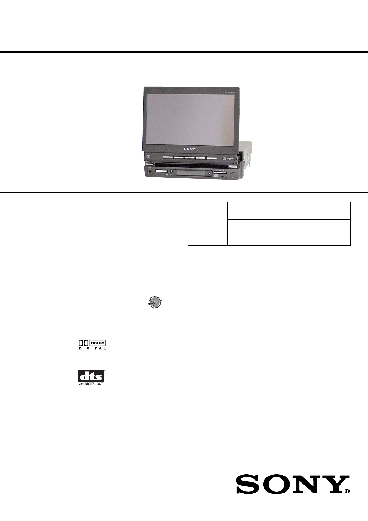
XAV-A1
SERVICE MANUAL
Ver. 1.2 2005.12
• US and Canadian models include the connection box (XA-123).
US and foreign patents licensed from Dolby Laboratories.
Copyrights
This product incorporates copyright
protection technology that is protected by
method claims of certain U.S. patents, other
intellectual property rights owned by
Macrovision Corporation, and other rights
owners. Use of this copyright protection
technology must be authorized by
Macrovision Corporation, and is intended for
home and other limited viewing uses only
unless otherwise authorized by Macrovision
Corporation. Reverse engineering or
disassembly is prohibited.
Manufactured under license from Dolby
Laboratories.
“Dolby”, “Pro Logic”, and the double-D
symbol are trademarks of Dolby
Laboratories.
“DTS” and “DTS 2.0 + Digital Out” are
trademarks of Digital Theater Systems, Inc.
AUDIO POWER SPECIFICATIONS (US model only)
AUDIO POWER SPECIFICATIONS (US model only)
POWER OUTPUT AND TOTAL HARMONIC DISTORTION
POWER OUTPUT AND TOTAL HARMONIC DISTORTION
22 watts per channel minimum continuous average power into 4 ohms, 4 channels driven from
22 watts per channel minimum continuous average power into 4 ohms, 4 channels driven from
20 Hz to 20 kHz with no more than 5 % total harmonic distortion.
20 Hz to 20 kHz with no more than 5 % total harmonic distortion.
CEA2006 Standard
CEA2006 Standard
Power Output: 17 Watts RMS × 4 at
Power Output: 17 Watts RMS × 4 at
4 Ohms < 1% THD+N
4 Ohms < 1% THD+N
SN Ratio: 82 dBA
SN Ratio: 82 dBA
(reference: 1 Watt into 4 Ohms)
(reference: 1 Watt into 4 Ohms)
System
Laser Semiconductor laser
Signal format system
Monitor section
Display type Wide LCD color monitor
Size 7 in.
System TFT active matrix
Number of pixel
DVD/CD Player section
Signal-to-noise ratio
Frequency response
Wow and flutter
Harmonic distortion (DVD)
DVD
Section
OPEN/CLOSE Model Name Using Similar Mechanism NEW
Section Open/Close Mechanism Type DB-M03
NTSC (US, CND, E (NTSC))
PAL (RU, E (PAL), AUS, CH)
336,960 pixels
100 dB
10 – 20,000 Hz
Below measurable limit
0.01%
US Model
Canadian Model
E Model
Australian Model
Chinese Model
Russian Model
Model Name Using Similar Mechanism NEW
DVD Mechanism Type MDAU51
Optical Pick-up Name HPD-60
SPECIFICATIONS
Tuner section
FM
Tuning range
Intermediate frequency
Usable sensitivity
Frequency response
Selectivity 75 dB (400 kHz)
S/N ratio 64 dB (stereo)
Harmonic distortion at 1 kHz
Separation 35 dB at 1 kHz
87.5 - 107.9 MHz (US, CND, E (NTSC))
87.5 - 108MHZ (RU, E (PAL), AUS, CH)
10.7 MHz/550 kHz
9 dBf
30 - 15,000 Hz
69 dB (mono)
0.5% (stereo)
0.4% (mono)
– Continued on next page –
AV CENTER
9-879-879-03
2005L05-1
© 2005.12
Sony Corporation
eVehicle Division
Published by Sony Engineering Corporation
XAV-A1
AM
Tuning range
Intermediate frequency
Usable sensitivity
530 - 1,710 kHz (US, CND, E (NTSC))
531 - 1,602 kHz (RU, E (PAL), AUS, CH)
10.8 MHz / 450 kHz
30 µV
Amplifier section
Outputs Speaker outputs
Speaker impedance
Maximum power output
(sure seal connectors)
4 - 8 ohms
50 W × 4 (into 4 ohms, at 1 kHz)
General
Power requirements
Consumption current rating
Inputs Power supply (1)
Outputs Front PRE out (1)
Tone controls
Dimensions With monitor closed
Mass Approx. 1.7 kg
Supplied accessories
12 V DC, from car battery (negative
ground)
Max. 10 A
AUX (3)
Rear PRE out (1)
Subwoofer (mono) (2)
Power aerial relay control lead (1)
Power amplifier control lead (1)
Rear Monitor OUT (1)
Bass ±10 dB at 100 Hz
Tr eble ±10 dB at 10 kHz
Approx. 178 × 50 × 185 mm (W × H
× D)
Remote commander RM-X706 (1)
(incl. 1 lithium battery)
Parts for installation and
connections (1 set)
Operating Instructions (1 set)
Connection box for XM tuner (1)
(US, CND, E (NTSC))
CAUTION
The use of optical instruments with this
product will increase eye hazard.
As the laser beam used in this CD/DVD
player is harmful to eyes, do not attempt to
disassemble the cabinet. Refer servicing to
qualified personnel only.
CAUTION
Use of controls or adjustments or performance of procedures
other than those specified herein may result in hazardous radiation
exposure.
Notes on chip component replacement
• Never reuse a disconnected chip component.
• Notice that the minus side of a tantalum capacitor may be
damaged by heat.
Flexible Circuit Board Repairing
• Keep the temperature of the soldering iron around 270 ˚C
during repairing.
• Do not touch the soldering iron on the same conductor of the
circuit board (within 3 times).
• Be careful not to apply force on the conductor when soldering
or unsoldering.
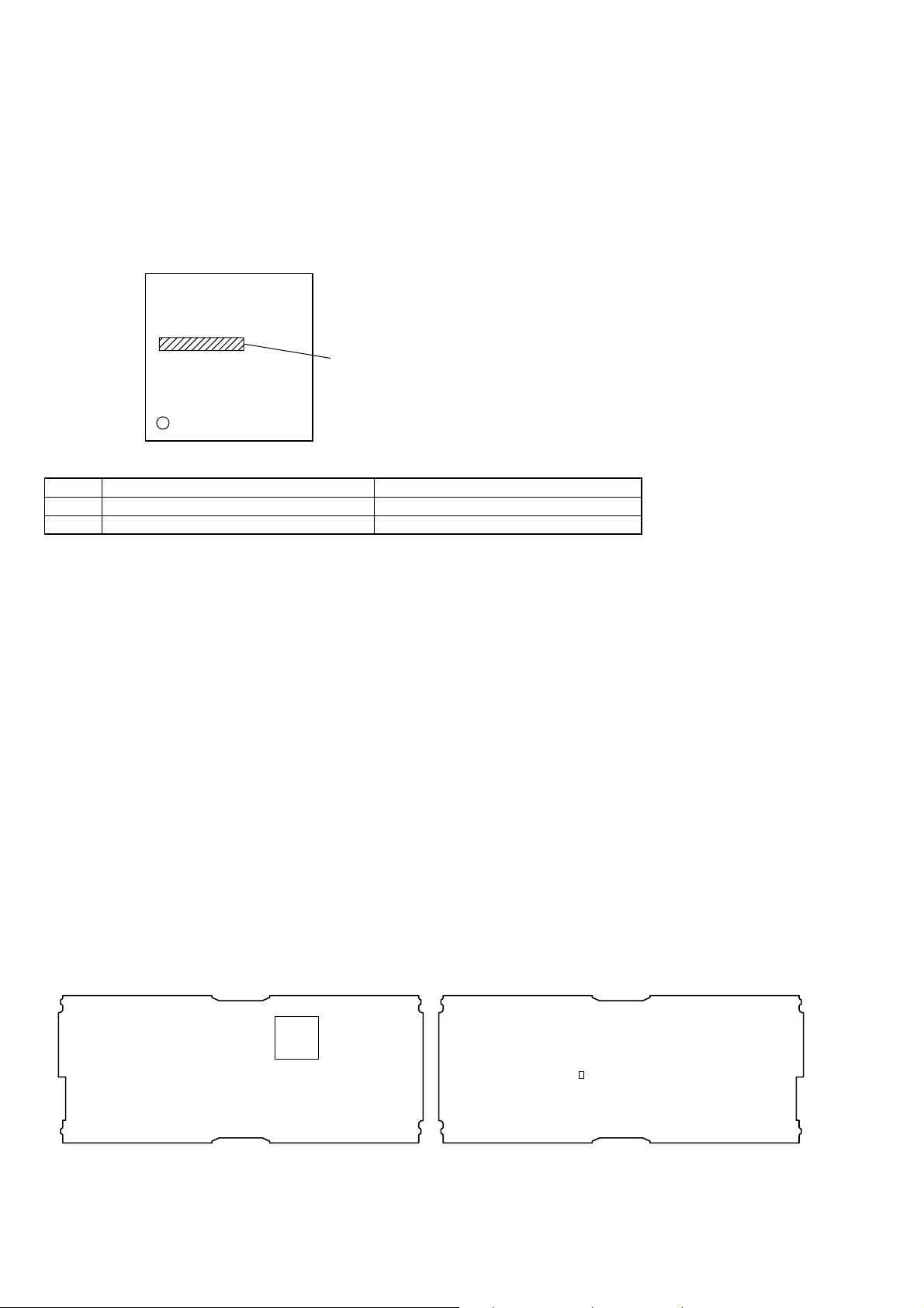
This label is located on the bottom of the chassis.
This product is classified as a CLASS 1 LASER PRODUCT.
Design and specifications are subject to
change without notice.
• Abbreviation
AUS: Australian model
CH : Chinese model
CND : Canadian model
RU : Russian model
SAFETY-RELATED COMPONENT WARNING!!
COMPONENTS IDENTIFIED BY MARK 0 OR DOTTED LINE
WITH MARK 0 ON THE SCHEMATIC DIAGRAMS AND IN
THE PARTS LIST ARE CRITICAL TO SAFE OPERATION.
REPLACE THESE COMPONENTS WITH SONY P ARTS WHOSE
PART NUMBERS APPEAR AS SHO WN IN THIS MANUAL OR
IN SUPPLEMENTS PUBLISHED BY SONY.
ATTENTION AU COMPOSANT AYANT RAPPORT
À LA SÉCURITÉ!
LES COMPOSANTS IDENTIFIÉS P AR UNE MARQ UE 0 SUR
LES DIAGRAMMES SCHÉMATIQUES ET LA LISTE DES
PIÈCES SONT CRITIQUES POUR LA SÉCURITÉ DE
FONCTIONNEMENT. NE REMPLACER CES COM- POSANTS
QUE PAR DES PIÈCES SONY DONT LES NUMÉROS SONT
DONNÉS DANS CE MANUEL OU D ANS LES SUPPLÉMENTS
PUBLIÉS PAR SONY.
This label is located on the bottom of the
chassis.
– US, Canadian models –
This label is located on the top exterior.
2

TABLE OF CONTENTS
XAV-A1
1. SERVICING NOTES ............................................... 4
2. GENERAL ................................................................... 8
3. DISASSEMBLY
3-1. Disassembly Flow ........................................................... 13
3-2. Front Panel ...................................................................... 14
3-3. Chassis secion.................................................................. 14
3-4. Bracket (SLIDER)........................................................... 15
3-5. SLIDER Board ................................................................ 16
3-6. Bracket (MOTOR) Assy (M2)......................................... 16
3-7. Bracket (MOTOR S) Assy (M1) .................................... 17
3-8. Monitor Block ................................................................. 17
3-9. Gear (1), Gear (4) ............................................................ 18
3-10. Mechanical Complete Assy (DB-M03) ........................... 18
3-11. LCD Board ...................................................................... 19
3-12. LCD ................................................................................. 19
3-13. DVD-ROM Mechanism Deck (MDAU51)...................... 20
3-14. MAIN Board.................................................................... 20
3-15. SERVO Board.................................................................. 21
3-16. Clamp Chassis Assy, Disc Assy Plate ............................. 21
3-17. DVD Chassis Assy ........................................................... 22
4. ELECTRICAL ADJUSTMENTS......................... 23
5. DIAGRAMS
5-1. Block Diagram – SERVO Section –................................ 24
5-2. Block Diagram – AUDIO/VIDEO Section – .................. 25
5-3. Block Diagram – CPU Section –..................................... 26
5-4. Block Diagram
– GRAPHIC/BUS CONTROL Section –........................ 27
5-5. Block Diagram – MONITOR Section –.......................... 28
5-6. Block Diagram
– PANEL, POWER SUPPLY Section – .......................... 29
5-7. Block Diagram – CONNECTION BOX Section – ......... 30
5-8. Printed Wiring Boards – SERVO Section – .................... 32
5-9. Schematic Diagram – SERVO Section (1/3) – ................ 33
5-10. Schematic Diagram – SERVO Section (2/3) –................ 34
5-11. Schematic Diagram – SERVO Section (3/3) –................ 35
5-12. Printed Wiring Boards – SLIDER Section – ................... 36
5-13. Schematic Diagram – SLIDER Section – ....................... 37
5-14. Printed Wiring Boards – MAIN Section (1/2) –.............. 38
5-15. Printed Wiring Board – MAIN Section (2/2) – ............... 39
5-16. Schematic Diagram – MAIN Section (1/10) – ................ 40
5-17. Schematic Diagram – MAIN Section (2/10) – ................ 41
5-18. Schematic Diagram – MAIN Section (3/10) – ................ 42
5-19. Schematic Diagram – MAIN Section (4/10) – ................ 43
5-20. Schematic Diagram – MAIN Section (5/10) – ................ 44
5-21. Schematic Diagram – MAIN Section (6/10) – ................ 45
5-22. Schematic Diagram – MAIN Section (7/10) – ................ 46
5-23. Schematic Diagram – MAIN Section (8/10) – ................ 47
5-24. Schematic Diagram – MAIN Section (9/10) – ................ 48
5-25. Schematic Diagram – MAIN Section (10/10) – .............. 49
5-26. Printed Wiring Board – LCD Section (1/2) –.................. 50
5-27. Printed Wiring Boards – LCD Section (2/2) – ................ 51
5-28. Schematic Diagram – LCD Section (1/3) –..................... 52
5-29. Schematic Diagram – LCD Section (2/3) –..................... 53
5-30. Schematic Diagram – LCD Section (3/3) –..................... 54
5-31. Printed Wiring Board – KEY Board –............................. 55
5-32. Schematic Diagram – KEY Board – ............................... 55
5-33. Printed Wiring Boards – DISPLAY Boards – ................. 56
5-34. Schematic Diagram – DISPLAY Section –..................... 57
5-35. Printed Wiring Board
– XA-123 Board – (US, Canadian models only)............. 58
5-36. Schematic Diagram
– XA-123 Board – (US, Canadian models only)............. 59
6. EXPLODED VIEWS
6-1. Front Panel Section ......................................................... 85
6-2. Detach Front Panel Section ............................................. 86
6-3. LCD Cover Assy Section................................................. 87
6-4. Monitor Section............................................................... 88
6-5. Open/Close Mechanism Deck Section (DB-M03).......... 89
6-6. Chassis Section................................................................ 90
6-7. MAIN Board Section....................................................... 91
6-8. MDAU51 DVD ROM Mechanism Deck Section............ 92
6-9. Connection Box
(XA-123) (US, Canadian models only)........................... 93
7. ELECTRICAL PARTS LIST................................ 94
3
XAV-A1
SECTION 1
SERVICING NOTES
NOTES ON HANDLING THE OPTICAL PICK-UP
BLOCK OR BASE UNIT
The laser diode in the optical pick-up block may suffer electrostatic
break-down because of the potential difference generated by the
charged electrostatic load, etc. on clothing and the human body.
During repair, pay attention to electrostatic break-down and also
use the procedure in the printed matter which is included in the
repair parts.
The flexible board is easily damaged and should be handled with
care.
NOTES ON LASER DIODE EMISSION CHECK
Never look into the laser diode emission from right above when
checking it for adjustment. It is feared that you will lose your sight.
UNLEADED SOLDER
Boards requiring use of unleaded solder are printed with the leadfree mark (LF) indicating the solder contains no lead.
(Caution: Some printed circuit boards may not come printed with
the lead free mark due to their particular size)
: LEAD FREE MARK
Unleaded solder has the following characteristics.
• Unleaded solder melts at a temperature about 40 ˚C higher
than ordinary solder.
Ordinary soldering irons can be used but the iron tip has to be
applied to the solder joint for a slightly longer time.
Soldering irons using a temperature regulator should be set to
about 350 ˚C.
Caution: The printed pattern (copper foil) may peel away if
the heated tip is applied for too long, so be careful!
• Strong viscosity
Unleaded solder is more viscou-s (sticky, less prone to flow)
than ordinary solder so use caution not to let solder bridges
occur such as on IC pins, etc.
• Usable with ordinary solder
It is best to use only unleaded solder but unleaded solder may
also be added to ordinary solder.
Playable discs
Format of discs
DVD VIDEO
DVD-R*
DVD-RW*
DVD+R*
DVD+RW*
Video CD
Audio CD
CD-R*
CD-RW*
*Discs that are not finalized cannot be played.
“DVD VIDEO”, “DVD-R”, “DVD-RW”, “DVD+R”,
and “DVD+RW” are trademarks.
DVD
A DVD contains both audio and visual data.
A 12-cm disc can hold 7 times the amount of
data contained in a CD-ROM, which equals
to 4 consecutive hours of playing time (8
hours for double-sided discs). DVDs are
divided into 4 types: single sided single layer,
single sided double layer, double sided single
layer, and double sided double layer.
Video CD (VCD)
A Video CD can contain both audio and
visual data on a disc with the same size as a
regular Audio CD. The playing time is 74
minutes for a standard 12-cm CD.
Audio CD
An Audio CD containing audio data. The
playing time is 74 minutes for a standard 12cm CD.
CD-Recordable (CD-R)
With a CD-R, you can edit audio data. You
can write information on a CD-R only once.
CD-Rewritable (CD-RW)
With a CD-RW, you can edit audio data. You
can write information on a CD-RW again and
again.
CD-Extra
A CD-Extra has two sections (sessions) for
audio and data respectively. You can only
play the section of audio on this unit.
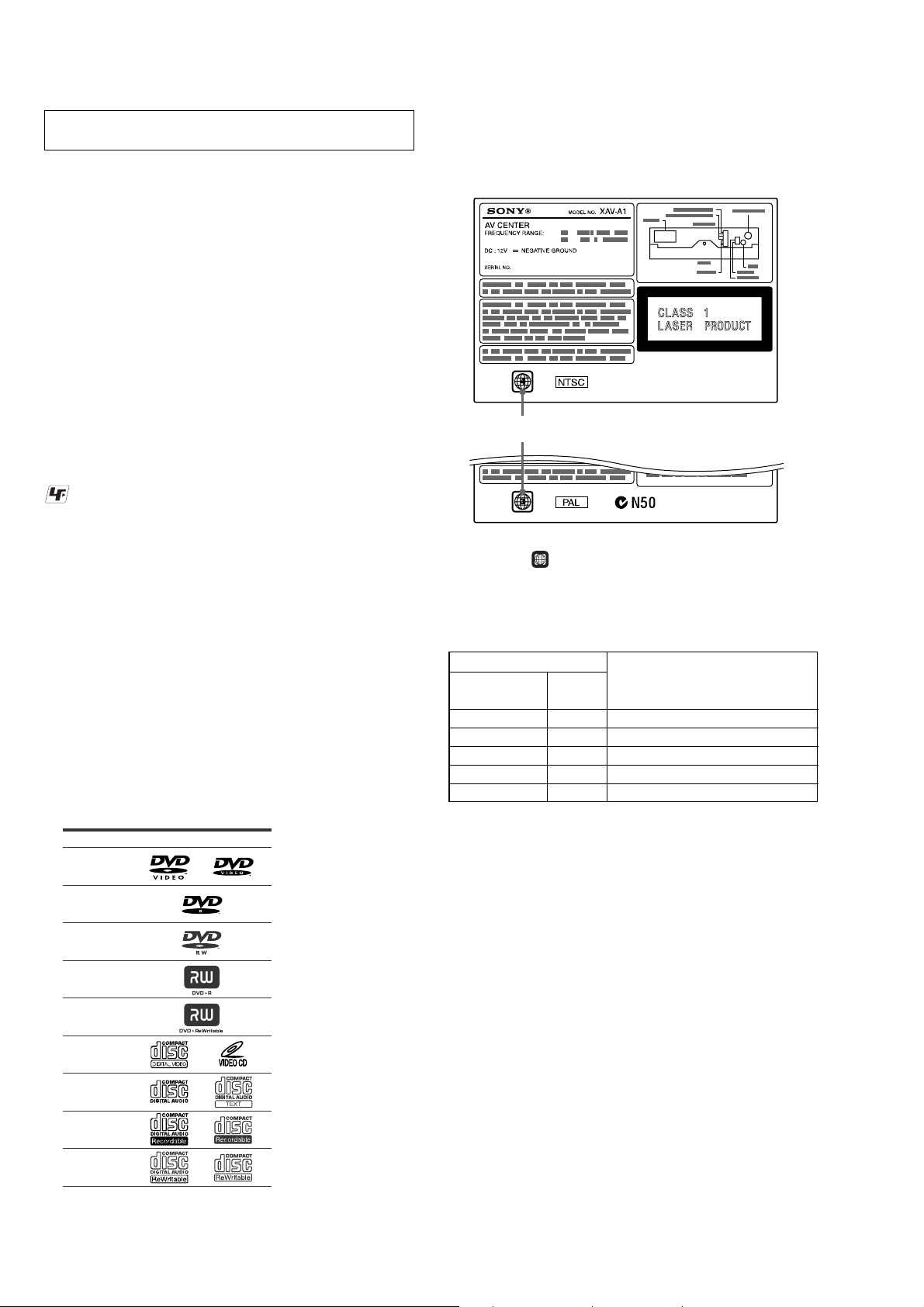
REGION CODE
This system is used to protect software copyrights.
The region code is located on the bottom of the unit, and only DVDs
labeled with an identical region code can be played on this unit.
Region code
ALL
DVDs labeled
can be also played on this unit.
If you try to play any other DVD, the message “Can not play” will
appear on the monitor screen. Depending on the DVD, no region
code may be labeled even though playing the D VD is prohibited by
area restrictions.
Label indication
Signal format Region Destination
system code
NTSC 1 US, Canadian models
PAL3E (P AL), Australian models
NTSC 4 E (NTSC) model
PAL5Russian model
PAL6Chinese model
Notes
• You can play DVD-Rs/DVD-RWs, DVD+Rs/
DVD+RWs and CD-Rs/CD-RWs designed for audio
with this unit. However, depending on the recorded
conditions, you cannot play some discs.
• You cannot play CD-Rs/CD-RWs, DVD-Rs/DVDRWs or DVD+Rs/DVD+RWs that are not finalized.
• Discs created in Packet Write format cannot be played.
• The discs listed below cannot be played on this unit:
– 8-cm discs
– CD-ROM (the data other than the MP3 or JPEG files)
– CD-G
– Photo-CD
– VSD (Video single disc)
– DVD-ROM (the data other than the MP3 or JPEG
files)
– DVD-RAM
– DVD-Audio
– CPRM
– Active-Audio (Data)
– CD-Extra (Data)
– Mixed CD
– SVCD (Super Video CD)
– CDV
– CD-F
– SACD (Super
Audio CD)
4
XAV-A1
NOTE WHEN REPLACING CHASSIS (MAIN) ASSY OR OPEN/CLOSE MECHANISM DECK (DB-M03)
The shape of CHASSIS (MAIN) ASSY has been partially changed in the midway of production.
Along with this modification, two screws that secure the Hook Assy and Front Panel have been also changed. Be sure to replace two screws
(Refer to the “EXPLODED VIEWS 6-1. FR ONT PANEL SECTION Ref. No. 6” (See page 85)) that secure the Hook Assy and Front Panel
simultaneously when replacing the CHASSIS (MAIN) ASSY or OPEN/CLOSE MECHANISM DECK (DB-M03) of the set having the
serial No. listed below.
SERIAL No.
Destination Serial No.
US, Canadian models 0010001~0014956
E (PAL), Australian models 0040001~0042360
E (NTSC) model 0080001~0080326
Russian model 0120001~0120839
Chinese model 0060001~0060626
Parts for witch e xchange simultaneously is mecessory Parts exchanged simultaneously
Ref. No. Part No. Description Ref. No. Part No. Description
201 A-1086-575-A OPEN/CLOSE MECHANISM DECK (DB-M03) 2 9-885-097-15 HOOK ASSY
235 X-2059-718-2 CHASSIS (MAIN) ASSY 6 9-885-084-87 SPECIAL SCREW
Note: Be sure to replace Ref. No.2 and Ref. No. 6 simultaneously when replacing Ref. No. 201 or Ref. No. 235.
NOTE WHEN REPLACING THE MAIN BOARD
1. Destination Setting
The MAIN board used in this set has different mounted parts according to the destination, but the mounted MAIN board supplied (9-885085-49) is exclusive for the US, Canadian, and E (NTSC) models only. Accordingly , when replacing the MAIN board for Russian, E (PAL),
Australian, and Chinese models, add or replace the parts following the table shown below.
Destination C272, C273 (Replacement) R161 (Addition) R162 (Addition) R163 (Addition)
Russian model 9-885-087-71
CK1H153KPUBNG 0.015uF SHORT CHIP 0 SHORT CHIP 0
E (PAL), Australian, Chinese 9-885-087-71 9-885-087-70
models CK1H153KPUBNG 0.015uF SHORT CHIP 0 SHORT CHIP 0
No mount
9-885-087-70 9-885-087-70
No mount
9-885-087-70
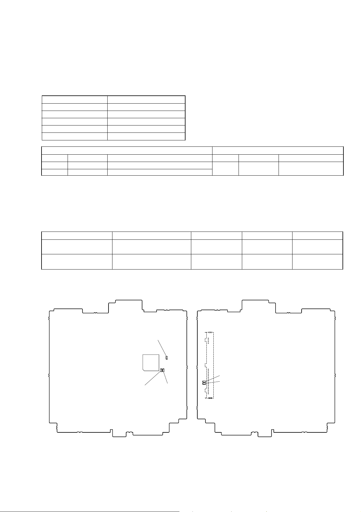
Parts Location:
– MAIN BOARD (Conductor Side) –– MAIN BOARD (Component Side) –
(RU, E (PAL), AUS, CH)
R163
IC101
TU251
C272
C273
• Abbreviation
AUS: Australian model
CH : Chinese model
RU : Russian model
R161
(E (PAL), AUS, CH)
R162
(RU)
2. Other Attention
If the mounted MAIN board was replaced, be sure refer to Technical News published separately.
5
XAV-A1
K
Ver. 1.1
NOTE WHEN REPLACING IC1 AND R197 ON THE XA-123 BOARD
There are two types of IC1 on the XA-123 board. Because IC1 has the combination with R197, the type of IC1 is confirmed by following
FLASH/MASK Type Discrimination, and R197 is replaced at the same time if necessary. (Be sure to confirm the type of new IC1, because
the supplied type cannot be specified by situations of the service parts)
Also when replacing R197, it is replaced after the type of IC1 is confirmed.
FLASH/MASK T ype Discrimination
FLASH/MASK type can be discriminated by printing of IC1 on the XA-123 board.
Back Print of IC1
NEC JAPAN
FLASH Type : D78F0078G
MASK Type : 780076GK
Combination Table
Type IC1 R197
FLASH 9-885-085-15 IC µPD78D0078GK-9E/7704AA 1-216-833-11 METAL CHIIP 10K 5% 1/10W
MASK 9-885-098-12 IC µPD780076GK-668-9ET-A 1-216-864-11 SHORT CHIIP 0
About the Replacement of IC1
Case1:
When IC before replacing is FLASH type, and new IC is MASK type.
R197 is replaced with 1-216-864-11 SHORT CHIIP 0 at the same time as replacing IC1.
Case2:
When IC before replacing is MASK type, and new IC is FLASH type.
R197 is replaced with 1-216-833-11 METAL CHIIP 10K 5% 1/10W at the same time as replacing IC1.
Case3:
When IC before replacing is FLASH type, and new IC is FLASH type.
IC1 is only replaced.
Case4:
When IC before replacing is MASK type, and new IC is MASK type.
IC1 is only replaced.
About the Replacement of R197
When replacing only R197, be sure to confirm the type of IC1 by above-mentioned FLASH/MASK Type Discrimination.
Case1:
When IC1 is FLASH type.
Replace with 1-216-833-11 METAL CHIIP 10K 5% 1/10W.
Case2:
When IC1 is MASK type.
Replace with 1-216-864-11 SHORT CHIIP 0.
Parts Location:
– XA-123 Board (Component Side) –
– XA-123 Board (Conductor Side) –
IC1
R197
6
JIG ON REPAIRING
SLIDER board
(CN2)
SLIDER board
(CN1)
LCD board
(CN1006)
extension cable (34P) (Part No.: J-2502-098-1)
(LCD board (CN1006)-SLIDER board (CN2))
MAIN board
(CS602)
extension cable (53P) (Part No.: J-2502-097-1)
(MAIN board (CS602)-SLIDER board (CN1))
• When repairing this set, etc., connect the extension cable as the figure shown below.
XAV-A1
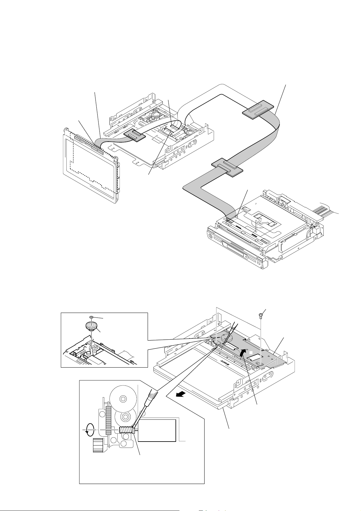
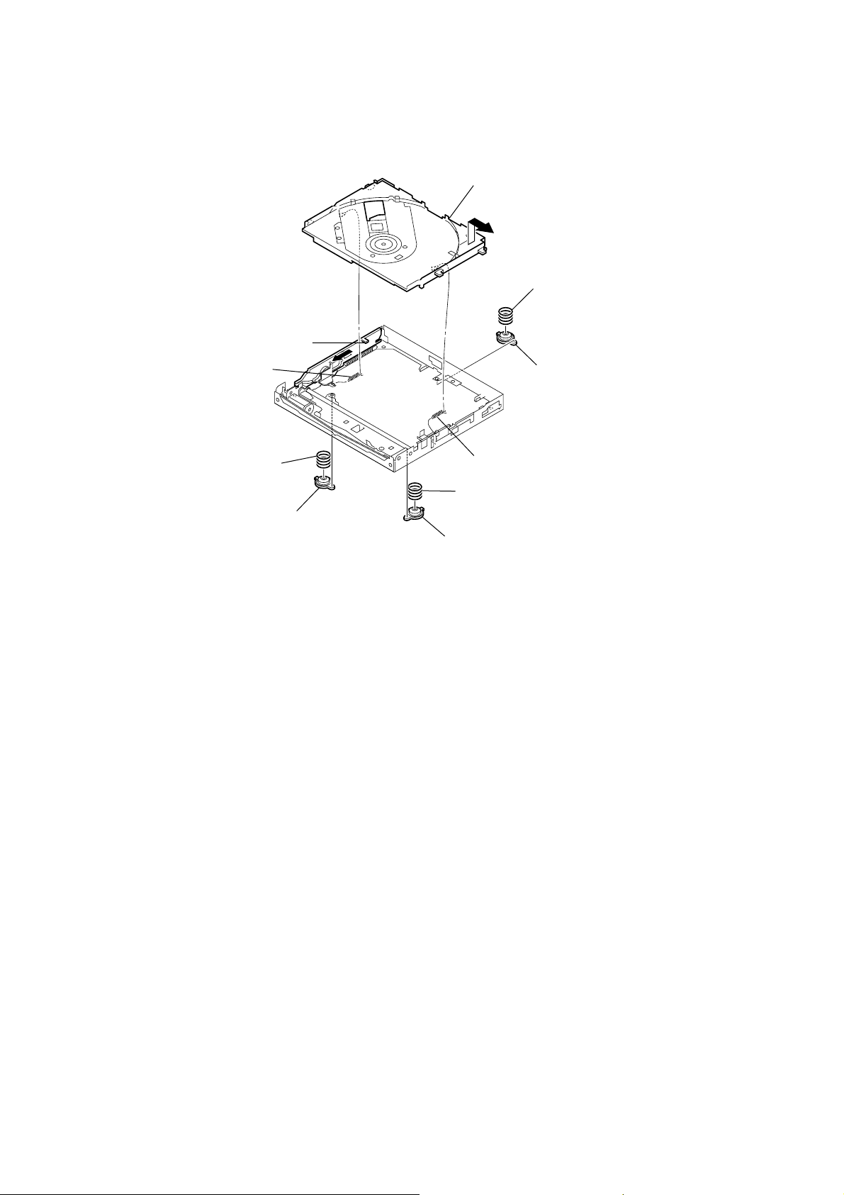
HOW TO PULL OUT MONITOR BLOCK IN CASE ELECTRICITY DOES NOT CIRCULATE
• When monitor block does not open by fault, pull out monitor block in the following procedures.
B
3
Rotate the worm gear in the direction of arrow B.
for pulling the monitor block.
6
stopper washer
(gear 1)
7
gear (1 S)
1
two screws
A
4
8
Pull the monitor block.
(M2)
5
2
Open the bracket (slider)
in the direction of arrow A.
bracket (slider)
Note: Don't touch except the gray portion of worm gear.
7
XAV-A1
SECTION 2
GENERAL
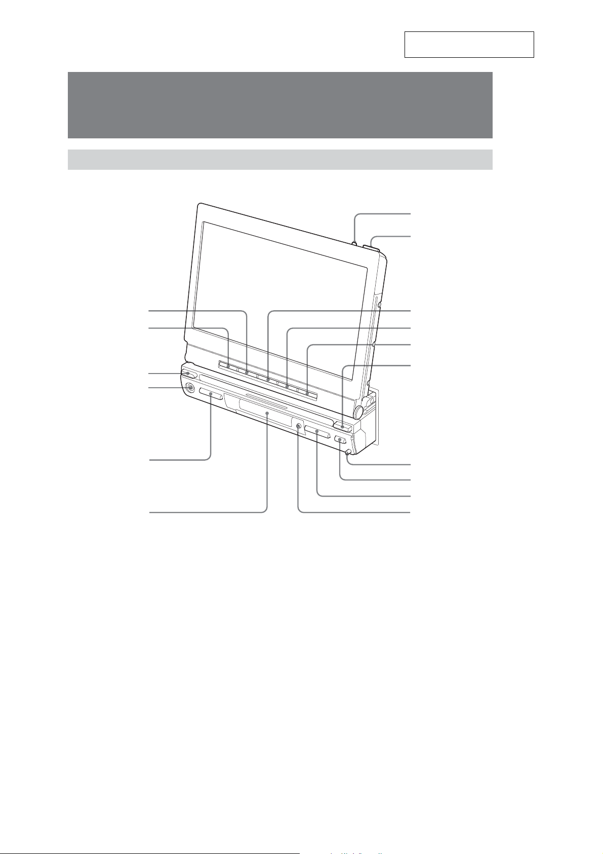
Location of Controls
Main unit
Monitor Open
This section is extracted from
instruction manual.
7
8
1
2
3
4
5
6
Refer to the pages listed for details.
1 ZxZ button
2 SOURCE button
3 SOURCE button
4 A/V IN jack
5 VOL –/+ button
6 Display window
7 TILT button
8 OPEN/CLOSE button
9
0
qa
qs
qd
qf
qg
qh
9 ANGLE – button
0 ANGLE + button
qa SLIDE button
qs MODE button
qd RELEASE button
qf Z (eject) button
qg SEEK –/+ ./> button
qh OFF button
* Warning when installing in a car without an ACC (accessory) position on the ignition key
After turning off the ignition, be sure to press OFF on the unit for 2 seconds to turn off the clock display.
Otherwise, the clock display does not turn of
f and this causes battery drain.
8
q
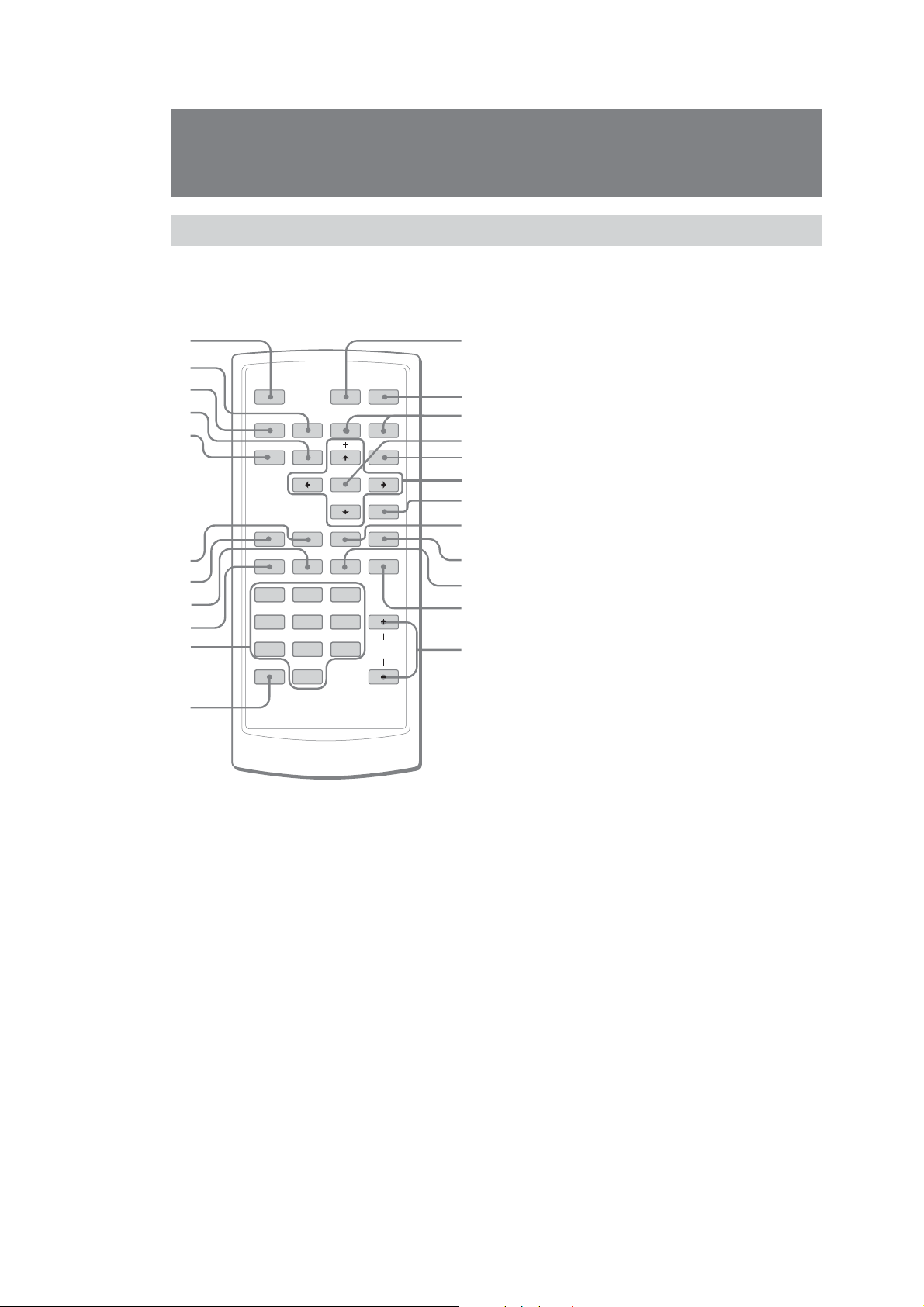
Location of Controls
Card remote commander RM-X706
The unit can be operated with the card remote commander. For safety, stop the car before
using the card remote commander, or have a passenger operate it.
qs ATT button
1
2
AT T
3
OFF
DVD
BX
4
5
6
7
8
9
q;
SRC
x
TOP MENU
MODE
SHUF
REP
SEARCH
AUDIO
12
45 6
78 9
CLEAR
0
ENTER
EQ7 ZxZ
SUBTITLE
3
>.
MENU
O
ANGLE
VOL
qa
Refer to the pages listed for details.
1 OFF button
To power off the source.
2 x button
To stop the source (VCD/DVD).
3 SRC (SOURCE) button
To power on/change the source (CD/DVD/TUNER/
AUX/TV*
4 TOP MENU button
To display the top menu on a DVD.
5 MODE button
To select the radio band (FM/AM)/select AUX/select
TV/select the unit.
6 SHUF button
7 REP button
8 AUDIO button
To change the audio output (VCD/DVD).
9 SEARCH button (VCD*2/DVD)
0 Number buttons
qa CLEAR button
To cancel entered numbers.
1
).
s
qd
qf
qg
qh
qj
qk
ql
w;
wa
ws
wd
To attenuate the sound. To cancel, press again.
Turning off the sound temporarily.
When you press the button, the sound is turned off
and “ATT” appears on the display.
To restore the sound, press the button again
(or VOL +/–).
qd DVDu button
To start/pause playback.
qf ./> buttons
qg ENTER button
To complete a setting.
qh MENU button
To display a menu on a DVD.
qj
</M/m/, buttons
To move the cursor, or turn the pages.
qk O (Return) button
To return to the previous display, or previous
operation.
ql EQ7 button
To select an equalizer type (Xplod, Vocal, Club, Jazz,
New Age, Rock, Custom or Off).
w; ZxZ (Zone x Zone) button
To switch the front/rear output.
wa SUBTITLE button
To change the subtitle language (DVD).
ws ANGLE button
To change the viewing angle (DVD).
wd VOL +/– buttons
To adjust the volume.
1
*
Only when an optional device is connected.
*2Only when PBC is Off.
Note
If the unit is turned off by pressing OFF for 2 seconds, it
cannot be operated with the card remote commander
unless SOURCE on the unit is pressed to
unit first.
Tip
See “Replacing the lithium battery” for details on how to
eplace the battery.
r
activate the
XAV-A1
9
XAV-A1
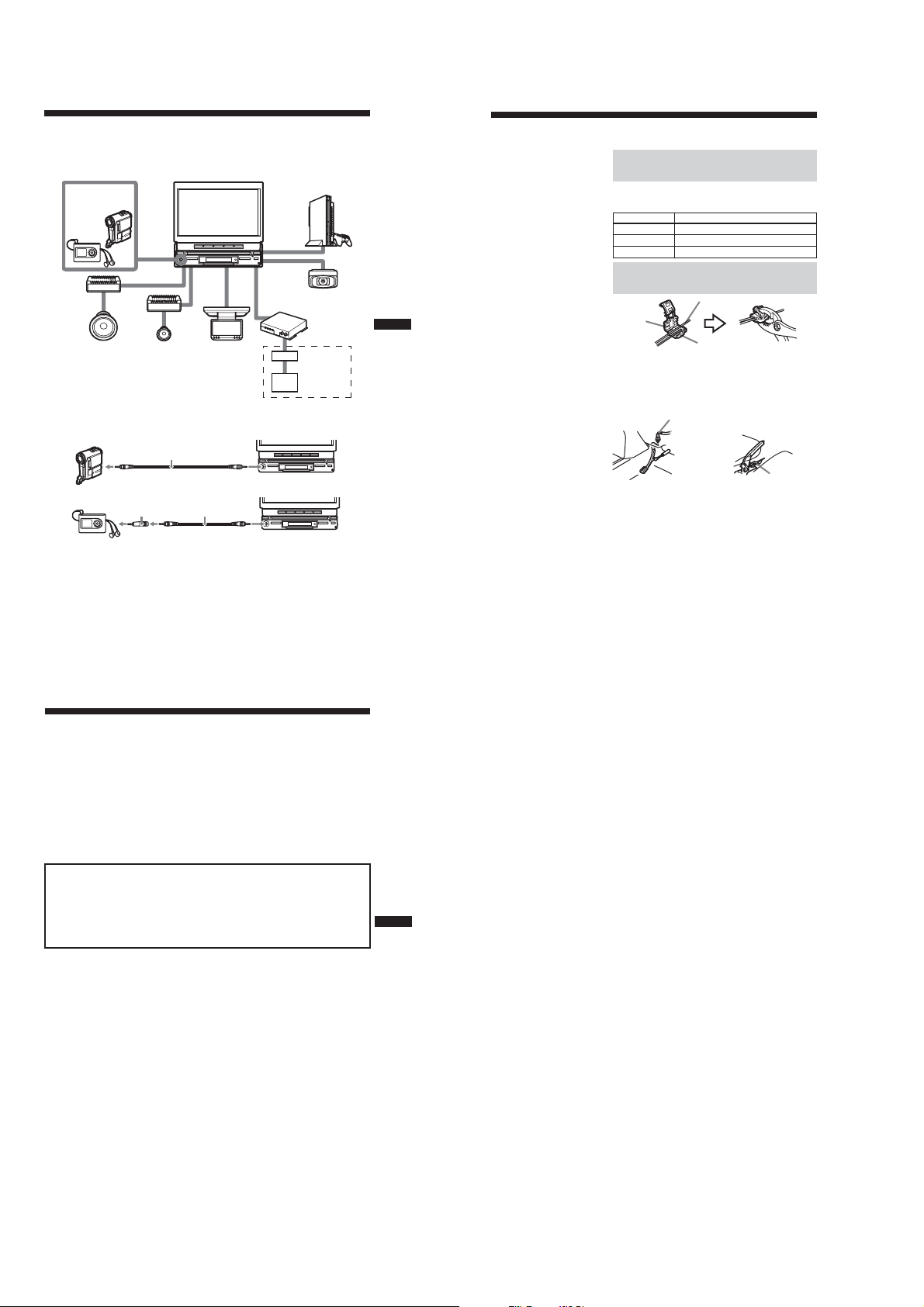
Connection Example
For details, see the section “1 Car Systems Connections” (pages 7 - 10). Be sure to refer also to the
documentation for all other components in the system.
System configuration
Walkman or
Video Camera
(optional)
Amplifier
(optional)
Subwoofer
(optional)
* Connect with supplied connecting cable 3. (Use a conversion plug 4 when you connect the audio equipment.)
When you connect the video camera
When you connect the audio player
Notes
• Be sure to connect the ground cord before connecting the amplifier.
• If you connect an optional power amplifier and do not use the built-in amplifier, the beep sound will be deactivated.
Amplifier
(optional)
Speaker
(optional)
A/V IN*
(Front)
(AUX 1)
SUB OUT
(MONO)
3
AV Center XAV-A1
FRONT L/R
REAR L/R
Rear Monitor
(optional)
34
REAR
MONITOR
OUT
AUX 2
AUX 3
AUX 3 and BUS
(US, Canadian)
Game (optional)
Back Camera
(optional)
TV Tuner XT-V70
(optional)
Connection Box
XA-123
XM Radio Tuner
(optional)
Connecting Information
For details, see the section “1 Car Systems Connections” (next page).
Connecting the cords
Notes
• Be sure to connect the power input
cord after all other cords are connected.
• If the parking brake switch cord is too
thin, connect the parking cord to the
parking brake switch cord directly
without using the tap.
Connect each cord using the taps. For the combination of each
cord, see the following table. Also, see the section “1 Car
Systems Connections” (next page).
Main unit side Car side
Orange/white Illumination signal cord
Purple/white Power terminal cord of the back lamp
Light green Parking brake switch cord
Using the tap
Parking brake switch cord
Tap 9
Connecting the parking cord
The mounting position of the parking brake switch cord depends
on your car. Refer to the system connection illustrations below
and consult your car dealer or your nearest Sony dealer for
further details.
Foot brake type Hand brake type
The cord for utilizing the back camera better
Purple/white cord (for the connection to the power terminal
cord of the back lamp)
If you connect the purple/white cord to the power terminal cord
of the back lamp, the image of back camera will be automatically
displayed on the monitor when a back lamp lights up. You can
adjust the parking location viewing the image of back camera
when you backup.
Parking brake
switch cord
Parking cord
(Light green)
Parking brake
switch cord
1 Car Systems Connections
Refer also to the documentation for all other components in the system.
Also see “Connecting Information” on page 6.
•Components listed here except for supplied accessories are available separately. When connecting such
components, be sure to also refer to their documentation.
For specifications and other information on separately available components, contact your dealer.
Prevention of accidents caused by short-circuits
To prevent the risk of accidents caused by short-circuits, connect the power supply leads (red and yellow)
only after all other wiring has been completed, and only with the ignition key in the OFF position.
Otherwise, accidental short-circuiting can lead to electric shock and to serious damage.
When a fuse has blown, check the wiring and locate the cause of the problem before replacing the fuse.
When replacing the fuse, be sure to use only a fuse of the same rating (ampere rating). Using a different
fuse or bridging the contacts with wire is highly dangerous and can lead to serious damage.
Make sure to connect all of the following leads.
Otherwise there is a risk of electric shock, damage to the equipment, or malfunction.
•Connect purple/white lead to back lamp lead of car.
•Connect orange/white lead to illumination signal lead of car.
•Connect light green lead to parking brake switch lead of car.
•Connect yellow lead to battery power supply of car.
•Connect red lead to accessory power supply of car.
•Connect black lead to metal point on car chassis.
* Do not mix up the yellow and red leads, as this will cause the memory contents to be lost.
Observe the following precautions.
Otherwise there is a risk of electric shock, damage to the equipment, or malfunction.
•Cover unused connectors with electrician’s tape to prevent accidental contact.
• Route FM/AM antenna cable, bus cable, RCA interconnects, and power supply leads as far apart from
each other as possible, to prevent noise interference.
•Always grasp the connector and do not pull the cable when disconnecting the bus cable or other cables.
Otherwise the cable may become detached.
Notes on the control and power supply leads
• The power antenna control lead (blue) supplies +12 V DC when turn on the tuner.
•When your car has built-in FM / AM antenna in the rear / side glass, connect the power antenna
control lead (blue) or the accessory power input lead (red) to the power terminal of the existing
antenna booster. For details, consult your dealer.
•A power antenna without relay box cannot be used with this unit.
Memory hold connection
When the yellow power input lead is connected, power will always be supplied to the memory circuit
even when the ignition key is turned of
f.
5
6
Notes on speaker connection
• Before connecting the speakers, turn the unit off.
• Use speakers with an impedance of 4 to 8 ohms, and with adequate power handling capacities to avoid
its damage.
• Do not connect the speaker terminals to the car chassis, or connect the terminals of the right speakers
with those of the left speaker.
• Do not connect the ground lead of this unit to the negative E terminal of the speaker.
• Do not attempt to connect the speakers in parallel.
• Connect only passive speakers. Connecting active speakers (with built-in amplifiers) to the speaker
terminals may damage the unit.
•To avoid a malfunction, do not use the built-in speaker wires installed in your car if the unit shar
common negative E lead for the right and left speakers.
• Do not connect the unit’s speaker cords to each other
.
es a
10
7
8
XAV-A1
Connecting without optional TV tuner unit (Except Russian)
RCA interconnects
Amplifiers
(optional)
*4
(optional)
RCA interconnects
(optional)
RCA interconnects
(optional)
White
White/black
Gray
Gray/black
Green
Green/black
Purple
Purple/black
*2
*1
*1*3
*1
SUB OUT (MONO)
Active subwoofer
(optional)
Rear speakers
(optional)
Front speakers
(optional)
Left
Front speakers
(optional)
Right
Left
Rear speakers
(optional)
Right
To a metal surface of the car
To the +12 V power terminal which is
energized at all times
To the +12 V power terminal which is
energized in the accessory position of
the ignition key switch
To a car’s illumination signal
To the + 12 V power terminal of the
back lamp lead of car
To AMP REMOTE IN of an optional
power amplifier
To the power antenna control lead or
power supply lead of antenna booster
*3*5
amplifier
Parking brake switch lead of car
*1 Be sure to connect the black ground lead to it first.
*2 First connect the black ground lead, then connect the yellow and red power input leads.
*3 When your car has built-in FM/AM antenna in the rear/side glass, see “Notes on the control and power
supply leads” (page 7).
*4 This connection is only for amplifiers. Connecting any other system may damage the unit.
*5 It is not necessary to connect this lead if there is no power antenna or antenna booster, or with a manually-
operated telescopic antenna.
Note on the accessory power input lead (red)
If there is no accessory position, connect to the +12 V power (battery) terminal which is energized at all times.
(US, Canadian)
REAR L/R
To t h e optional
back camera or a
video equipment
FRONT L/R
RC-104 (optional)
digital output
From car antenna
To game
etc.
To rear
monitor etc.
Black (0.35 m)
Yellow (0.35 m)
Red (0.25 m)
Orange/white (0.25 m)
Protection device
Blue/white (0.25 m)
Max. supply current 0.3 A
Blue (0.25 m)
Max. supply current 0.3 A
Tap 9
To XM tuner (optional)
Connection
box 1
AUX 3
REAR MONITOR OUT
Purple/White (5m)
Light green (2.5 m)
AUX 2
Power
supply
leads 2
(for main
unit)
Fuse (10 A)
Connecting with optional TV tuner unit (Except Russian)
Film antenna
Antenna cord
Tuner
To the +12 V power
amplifier
terminal which is
unit
energized in the
accessory position of the
ignition key switch. Be
sure to connect the black
ground lead first.
To a metal point
of the car
To the optional back camera
or a video equipment
(US, Canadian)
Connection box 1
TV tuner unit
XT-V70
(optional)
To XM tuner (optional)
AUX 3
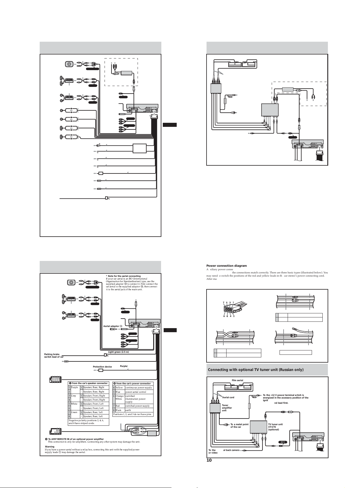
Connecting without optional TV tuner unit (Russian only)
RCA interconnects
Active subwoofer
(optional)
Rear speakers
(optional)
Front speakers
(optional)
Parking brake
switch lead of car
A AMP REM
To the + 12 V power terminal of the
back lamp lead of car
13 57
24 68
57
68
4
A To AMP REMOTE IN of an optional power amplifier
.$ && $ -$' /& $$- - %- '
Warning
0 # ) ) 12 && $ ) $%)
$ %$1- %- '
(optional)
SUB OUT (MONO)
RCA interconnects
(optional)
Amplifiers
RCA interconnects
(optional)
(optional)
Max. supply current 0.3 A
C from the car’s speaker connector
C from the car’s speaker connector
!
"# $$
% ! # $% &%$'
D from the car’s power connector
* Note for the aerial connecting
0 & $ 0+ 30
+4 %%45 $
$% %qd && ' $ &&
& $%%qd &&
6& - '
REAR L/R
To the optional
back camera or
video
RC-104 (optional)
FRONT L/R
digital output
Aerial adaptor qd
From car aerial*
To game etc.
To rear
monitor etc.
Light green (2.5 m)
Blue/white
Protection device
Purple/White (5m)
D from the car’s power connector
() &$ ) $
* ) &
+, $)&%
- )
% $)&% ) $
!*&
$$ % % # $'
See “Power connection diagram”
on next page for details.
This terminal is not
used in this case.
AUX 3
AUX 2
REAR MONITOR OUT
$
Power
supply
leads 1
(for main
unit)
Fuse
(10 A)
9
10
Power connection diagram
Auxiliary power connector may vary depending on the car. Check your car’s auxiliary power connector
diagram to make sure the connections match correctly. There are three basic types (illustrated below). You
may need to switch the positions of the red and yellow leads in the car stereo’s power connecting cord.
After matching the connections and switched power supply leads correctly, connect the unit to the car’s
power supply. If you have any questions and problems connecting your unit that are not converted in
this manual, please consult the car dealer.
Auxiliary power connector
Red
B
Yellow
4Yellow switched power supply
7Red continuous power supply
Red
Yellow
Red
A
Yellow
4Yellow continuous power supply
7Red switched power supply
Red
C
Yellow
the car without ACC position
Red
Yellow
Red
Yellow
Connecting with optional TV tuner unit (Russian only)
Film aerial
Aerial cord
Tuner
amplifier
unit
To a metal point
of the car
To the optional back camera
or video
9
10
To the +12 V power terminal which is
energized in the accessory position of the
ignition key switch. Be sure to connect the
black ground lead first.
TV tuner unit
XT-V70
(optional)
AUX 3
11
XAV-A1
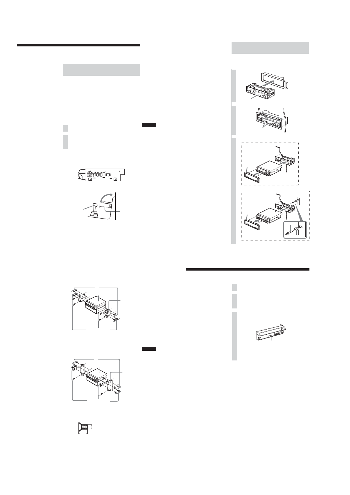
2 Installing the Main Unit
Installation angle
The unit should be installed within an
angle of 30 degrees from horizontal. If
this angle is exceeded, the monitor may
not open up or retract properly.
Note
Keep the units and connection cables
apart.
After all connections are made, install the main unit to the
dashboard.
Before installation
This unit is designed to be completely safe, but if not installed
correctly, it can cause accidents. Be sure to verify the following
points before installation.
Install the main unit to the in-dash location, and the amplifier unit
under the navigator’s seat, etc.
• If the monitor in the opened position is close to a airconditioning outlet, the outlet should be closed.
• Install the unit so that the monitor when opened up will not
block access to the hazard switch or other important controls.
•Do not install the unit (monitor) in locations which may be
subject to excessively low or high temperatures. (Otherwise the
unit may be deformed and the LCD may be damaged.)
Exposure to direct sunlight can also lead to high temperatures
and should be avoided.
Selecting the installation location
Set the ignition key to OFF or remove it.
1
Place the units in their intended mounting
2
locations to check the cable length and monitor
installation conditions.
Installation procedure precautions
• Perform the installation carefully. Dropping the unit or
otherwise subjecting it to strong impact or force may deform
the chassis, resulting in failure of the monitor loading
mechanism or other defects.
•To allow for proper opening and closing of the monitor, there
must be a clearance of at least 170 mm between the closest
position of the shift lever and the mounting surface for the unit.
Shift lever
N T/N T/N T/NT
Installation procedure
Mounting example
When installing this unit, be sure to close the monitor of the unit.
If the monitor is opened while installing and given too much
force, it may cause a malfunction.
182
1
0
mm
53
m
m
2
Claws
(US, Canadian)
3
NNTT
(Except US, Canadian)
At least 170 mm
from mounting
surface
Dashboard
0
qa
Dashboard
8
9
Fire wall
Notes
•Do not press the front panel buttons of
the unit during installation and do not
apply strong force.
•Do not place any objects on top of the
unit.
• If a salient of the genuine bracket
touches the unit due to its figure, and
makes attachment hard, process the
bracket by scraping the salient off.
• In some cases, the shift lever may touch the monitor when
moved to a certain position. Make sure that there is no
obstruction to driving operations.
•When installing this unit together with other car audio
equipment (single DIN slot size) in a stacked configuration,
install the main unit on top.
Toyota cars (illustration shows an example for a Toyota car)
Align the brackets of the factory-installed car stereo with the
mounting holes marked “T” on the side of the main unit, and use
the supplied screws to fasten the brackets. For Toyota cars, the
supplied screws 6 should be used.
Nissan cars
Align the brackets of the factory-installed car stereo with the
mounting holes marked “N” on the side of the main unit, and use
the supplied pan-head screws 6 to fasten the brackets.
6
XAV-A1
Screws of factoryinstalled car stereo
bracket
6
XAV-A1
Bracket of
factory-installed
car stereo
Bracket of
factory-installed
car stereo
11
12
3 After Installation and Connections
Start the car’s engine.
1
Verify that the brake lights, other lights, horn, turn
2
indicators, and all other electrical parts operate
normally.
Note
To avoid the possibility of damage, you
should not use a needle or push the
button too strongly
.
Use a mechanical-pencil or similar to push the Reset
3
button on the unit.
When you press the Reset button, the system becomes
operative.
Reset button
qa
qs
12
Screws of factoryinstalled car stereo
* Be sure to use only the supplied pan-head screws 6 for
installation. If any other screws are used, make sure they
conform to the requirements shown below.
Using longer screws can cause internal damage to the unit.
Damage can also occur if the screws are used directly on the
unit without the brackets of the factory-installed car stereo.
bracket
5 mm
6 mm
13
14
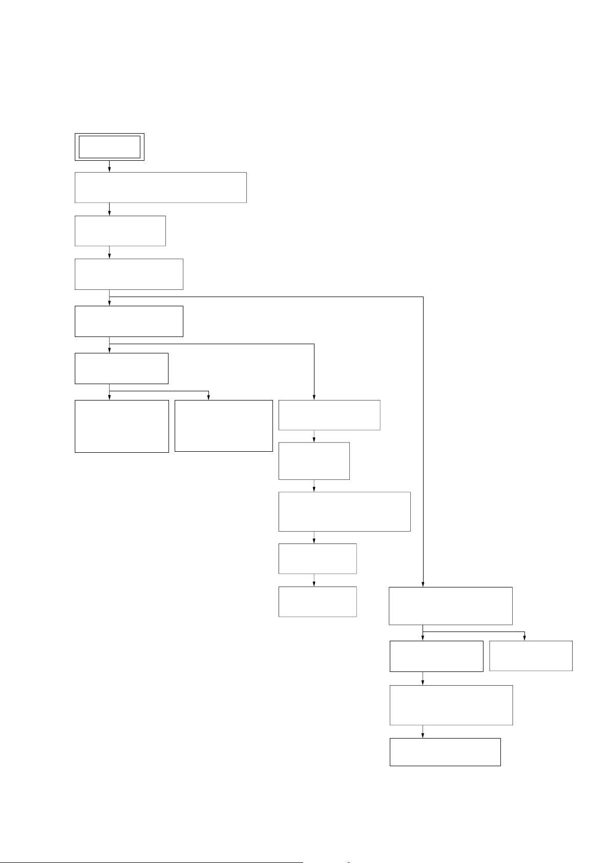
• This set can be disassembled in the order shown below.
3-1. DISASSEMBLY FLOW
SET
DETACH FRONT PANEL ASSY
(Note: Illustration of disassembly is omitted.)
3-2. FRONT PANEL
(Page 14)
3-3. CHASSIS SECTION
(Page 14)
3-4. BRACKET (SLIDER)
(Page 15)
XAV-A1
SECTION 3
DISASSEMBLY
3-5. SLIDER BOARD
(Page 16)
3-6. BRACKET
(MOTOR) ASSY
(M2)
(Page 16)
3-7. BRACKET
(MOTOR S) ASSY
(M1)
(Page 17)
3-8. MONITOR BLOCK
(Page 17)
3-9. GEAR (1),
GEAR (4)
(Page 18)
3-10.MECHANICAL COMPLETE
ASSY (DB-M03)
(Page 18)
3-11.LCD BOARD
(Page 19)
3-12.LCD
(Page 19)
3-13.DVD-ROM MECHANISM
3-15.SERVO BOARD
DECK (MDAU51)
(Page 20)
(Page 21)
3-14.MAIN BOARD
(Page 20)
3-16.CLAMP CHASSIS ASSY,
DISC ASSY PLATE
(Page 21)
3-17.DVD CHASSIS ASSY
(Page 22)
13
XAV-A1
)
Note: Follow the disassembly procedure in the numerical order given.
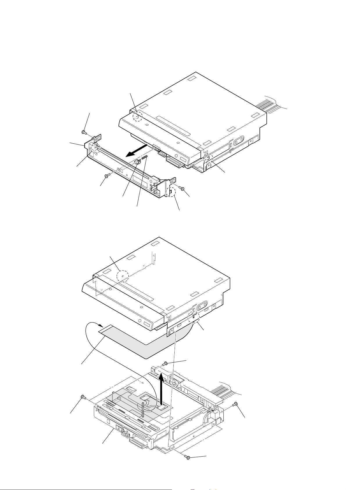
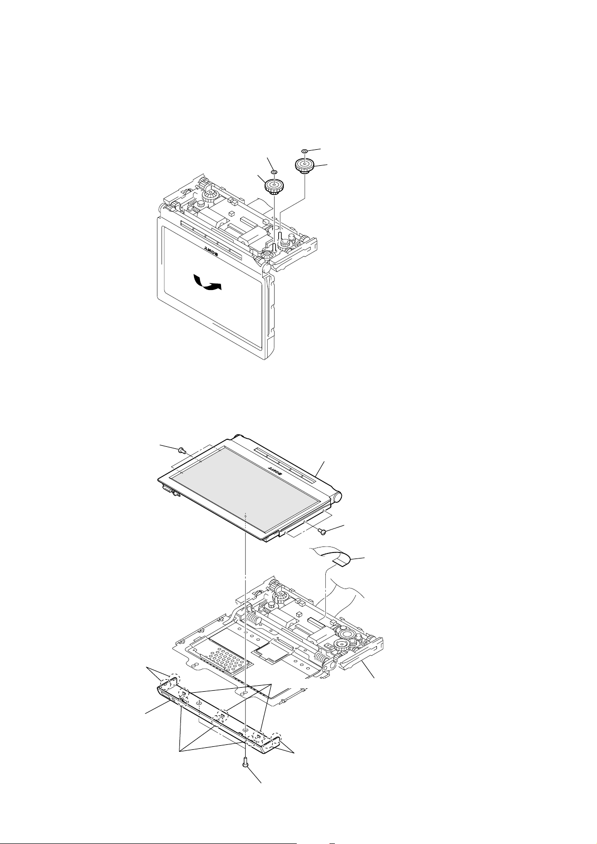
3-2. FRONT PANEL
4
claw
3
special screw
qa
front panel
8
5
claw
6
claw
screw (PTT2.6 × 5)
1
3-3. CHASSIS SECTION
5
0
boss
sensor slide
9
slide comp spring
7
2
claw
special screw
6
boss
14
4
two screws
(PTT2.6 × 5)
8
flexible cable
(CS602)
9
chassis section
7
1
screw
(PTT2.6 × 5)
3
two screws
(PTT2.6 × 5)
2
screw
(PTT2.6 × 5
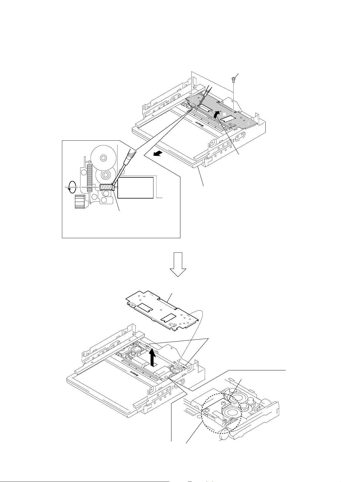
3-4. BRACKET (SLIDER)
B
A
1
two screws
(M2)
2
Open the bracket (slider)
in the direction of arrow A.
XAV-A1
3
Rotate the worm gear in the direction of arrow B.
for pulling the monitor block.
Note: Don't touch except the gray portion of worm gear.
5
monitor block
bracket (slider)
4
two convex portions
RS board
Note: Never remove RS Board as the position of gear
has been adjusted in the production.
15
XAV-A1
d
3-5. SLIDER BOARD
3
two connectors
(CN3, CN5)
4
screw (M2 × 3)
2
flexible (53P) board
(CN1)
3
connector
(CN6)
1
4
screw (M2 × 3)
5
SLIDER board
3
two connectors
(CN4, CN7)
flexible (34P) boar
(CN2)
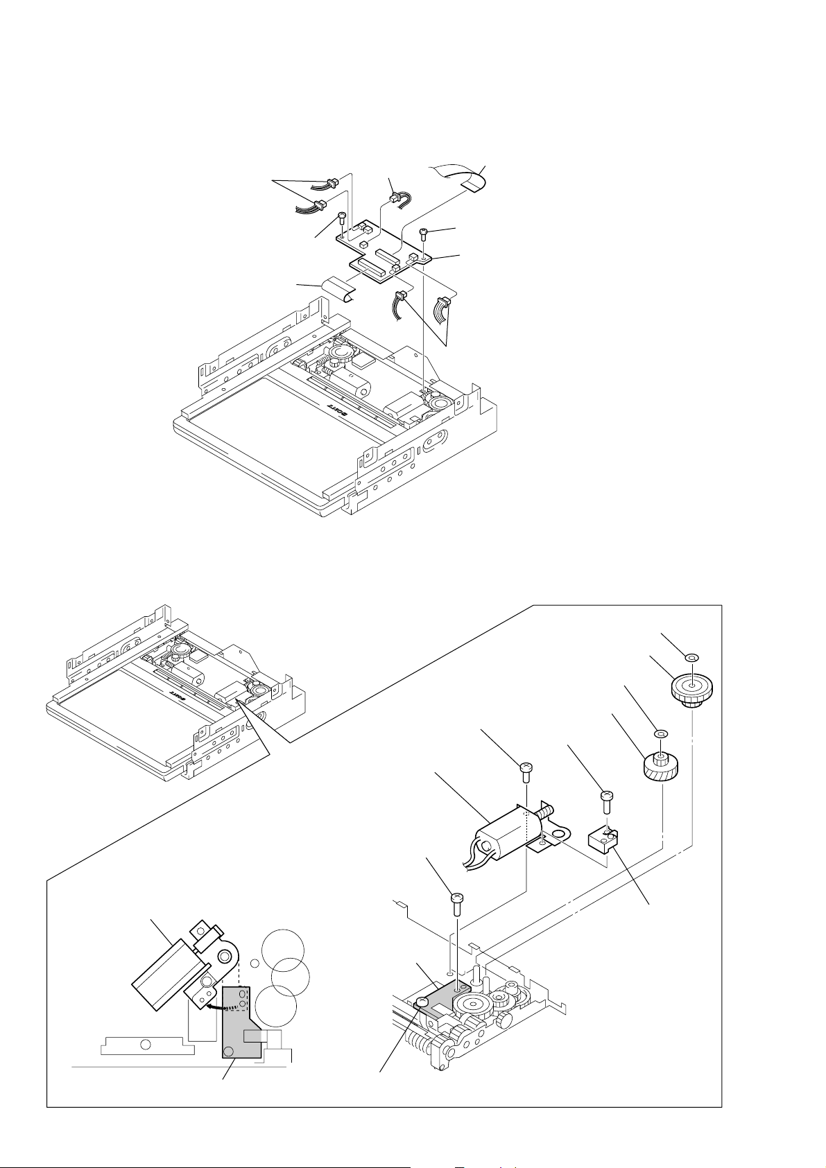
3-6. BRACKET (MOTOR) ASSY (M2)
8
Rotate and remove the bracket (motor) assy block.
5
special head screw
(M2)
qa
bracket (motor) assy
(M2)
6
tapping screw
RS board
1
stopper washer (gear 1)
3
stopper washer (gear)
4
gear (worm wheel)
9
serration screw
×
3)
(M2
2
gear (1)
0
spacer (PWB)
16
RS board
7
Loosen the special head screw
(M2).
Note: Never remove RS Board
as the position of gear has been adjusted
in the production.
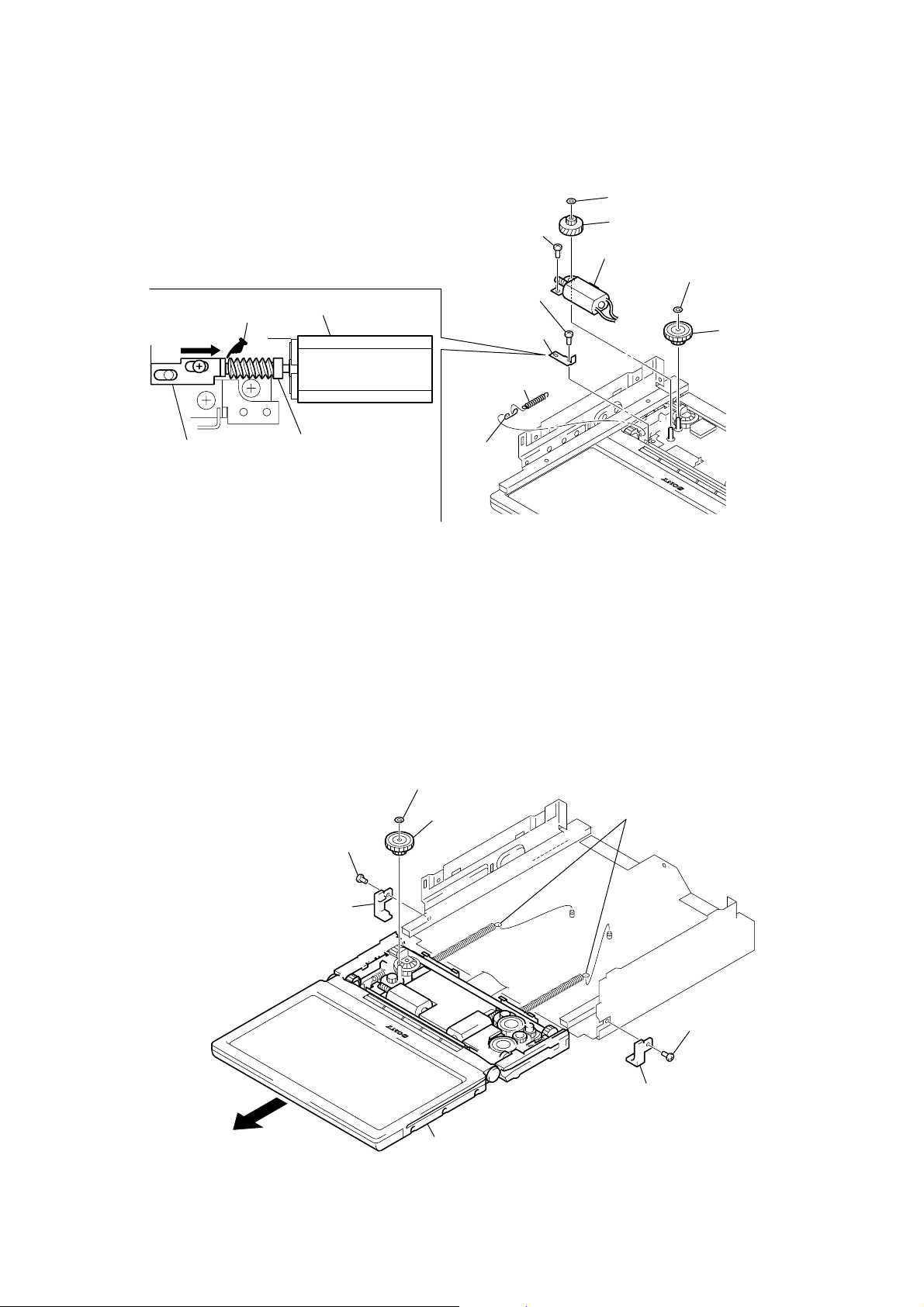
3-7. BRACKET (MOTOR S) ASSY (M1)
1
stopper washer (gear 1)
5
tension coil
spring (moniter)
3
stopper washer (gear)
2
gear (1 S)
7
screw (M2)
mark
9
screw
(M1.7 × 2.5)
6
joint
(spring)
4
gear (wheel S)
8
bracket (motor S) assy (M1)
bracket (motor S) assy (M1)
NOTE WHEN INST ALLING
THE BRACKET (R THRUST)
q;
bracket
(R thrust)
bracket (R thrust)
Note: When installing the bracket (R thrust),
no gap must be made at the
@
mark
portion of the gear (worm).
gear (worm)
)
XAV-A1
3-8. MONITOR BLOCK
7
3
screw (M2)
4
stopper (R)
5
stopper washer (gear 1)
6
gear (1 S)
9
monitor block
8
two tension springs (GT
1
screw (M2)
2
stopper (L)
17
XAV-A1
y
3-9. GEAR (1), GEAR (4)
Note1: For the gear (1) and gear (4), there is no problem whichever may be removed first.
3
stopper washer (gear)
4
gear (4)
1
stopper washer (gear 1)
2
gear (1)
Note2: When the gear (1) or gear (4) is removed,
the monitor section will be folded abruptly
by a spring force, thus requiring care for handling.
3-10. MECHANICAL COMPLETE ASSY (DB-M03)
6
three special screws
3
two claws
7
monitor section
6
three special screws
1
flexible (34P) board
(CN2)
18
5
LCD cover assy
3
three claws
4
three claws
3
two claws
2
two special screws
8
mechanical complete ass
(DB-M03)
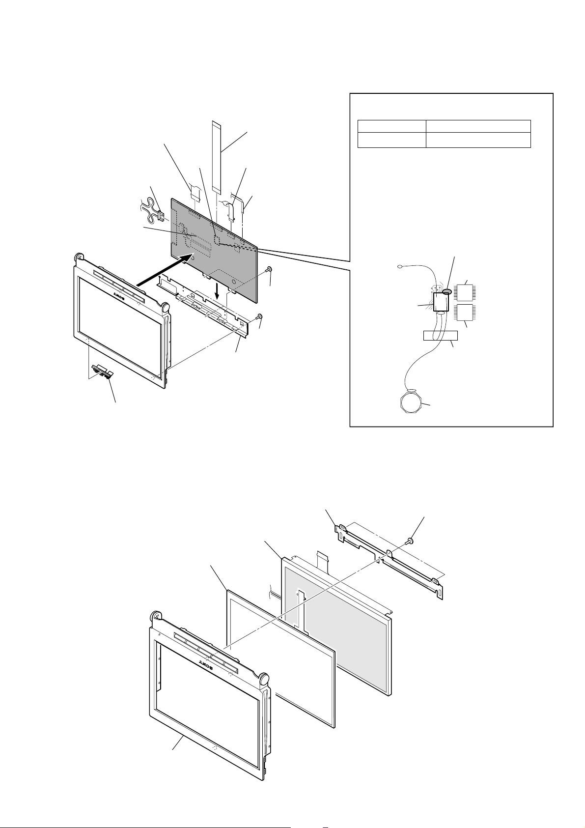
3-11. LCD BOARD
qa
LCD board
8
open button
0
LCD (1) bracket
9
three special screws
6
two special screws
4
flexible cable
(CN1005)
5
flexible cable
(CN1007)
3
flexible (34P) board
(CN1006)
2
flexible cable
(CN1001)
1
connector
(CN1004)
7
IC1011
IC1012
sheet
L1008
SUB board
SUB
board
– SUB board –
If replacing the SUB board,
disconnect the SUB board from the LCD board,
and clear off the remaining bond with a cutter,
etc. and then apply the bond and install new board.
In clearing off the remaining bond with a cutter,
take care not to damage the board or mounted parts.
For the bond application locations.
(SONY BOND SC608LV)
To secure the SUB boards, a special bond is required.
Part. No. Part Name
7-432-912-48 SONY BOND SC608LV
XAV-A1
3-12. LCD
5
LCD panel assy
4
touch panel
3
LCD
2
LCD (2) bracket
1
theree special screws
19
XAV-A1
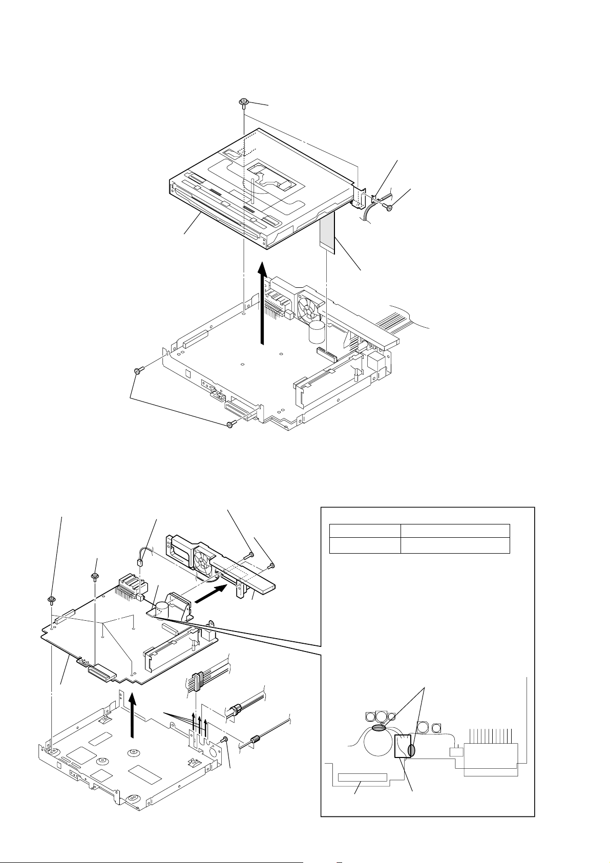
3-13. DVD-ROM MECHANISM DECK (MDAU51)
7
DVD-ROM
mechanism deck
(MDAU51)
4
two screws (SWW2.6 × 7)
5
2
6
35P 90mm FFC
(CS301)
cord bracket
1
screw (PTT2.6 × 5)
3
two screws
(PTT2.6
3-14. MAIN BOARD
3
four screws
(SWW2.6
2
9
MAIN board
×
screw
(SWW2.6
6)
×
5)
6
5
connector
(CS806)
×
5)
MUTE
board
two screws
(PTT2.6
7
two screws
(PTT2.6
8
heat sink
×
10)
×
To secure the MUTE boards, a special bond is required.
Part. No. Part Name
10)
7-432-912-48 SONY BOND SC608LV
– MUTE board –
If replacing the MUTE board,
disconnect the MUTE board from the MAIN board,
and clear off the remaining bond with a cutter,
etc. and then apply the bond and install new board.
In clearing off the remaining bond with a cutter,
take care not to damage the board or mounted parts.
For the bond application locations.
(SONY BOND SC608LV)
20
4
4
1
screw
(PTT2.6
×
10)
IC555
C550
CP1
MUTE board
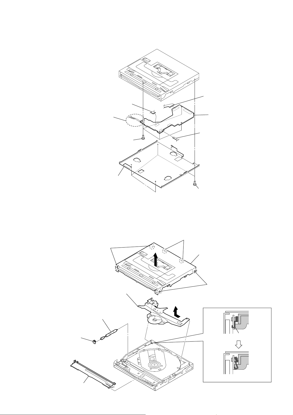
3-15. SERVO BOARD
d
5
Remove the clamp torsion spring
6
clamp chassis assy
8
gear shaft assy
7
shaft gear bracket
9
disc assy plate
clamp torsion spring
1
two claws
2
two claws
4
cover assy
3
two claws
3
Remove two solders
of the loading motor
lead wires (M1100).
4
flexible cable
(CS1301)
7
four screws
(SW2 × 4)
5
flexible cable
(CS1103)
8
6
flexible cable
(CS1102)
XAV-A1
SERVO boar
2
bottom cover assy
3-16. CLAMP CHASSIS ASSY, DISC ASSY PLATE
1
four screws
(PCS2 × 3.5)
21
XAV-A1
g
3-17. DVD CHASSIS ASSY
9
1
chassis DVD coil spring
Slide the slide rack.
0
DVD chassis assy
8
R damper coil sprin
(gold)
7
R damper
(gray)
4
F damper coil spring
(silver)
3
damper
(green)
2
chassis DVD coil spring
6
F damper coil spring
(silver)
5
damper
(green)
22
SECTION 4
e
– LCD Board (Side B) –
IC1033
U6
114
78
U7
U1
CN1010
15
SVR1002
R1054
SVR1001
R1115
ELECTRICAL ADJUSTMENTS
XAV-A1
VOLTAGE ADJUSTMENT
Setting:
digital voltmeter
LCD board
U1/U6/R1054/R1115
U7
Procedure:
1. Connect a digital voltmeter to the U6 and U7 on the LCD
board.
2. Adjust the SVR1001 on the LCD board so that the value of
digital voltmeter becomes +5.4 V ± 0.05 V.
3. Connect a digital voltmeter to the R1115 and U7 on the LCD
board.
4. Confirm that the value of digital voltmeter is +5.0 V ± 0.1 V.
5. Connect a digital voltmeter to the U1 and U7 on the LCD
board.
6. Adjust the SVR1002 on the LCD board so that the value of
digital voltmeter becomes –14.0 V ± 0.1 V.
7. Connect a digital voltmeter to the R1054 and U7 on the LCD
board.
8. Confirm that the value of digital voltmeter is +14.5 V ± 0.5 V .
Adjustment and Connection Location: LCD board
TOUCH PANEL ADJUSTMENT
Note: After the end of voltage adjustment, this adjustment is performed.
Procedure:
1. Turn the power on and set th FM mode.
2. Press the [OPEN/CLOSE] button to open the monitor.
3. Touch in order of [SOURCE], [MENU], [OTHER] and [Touch
Panel Adjust] on the monitor to display three points on the
monitor.
4. Touch in order of point [1], [2] and [3] on the monitor.
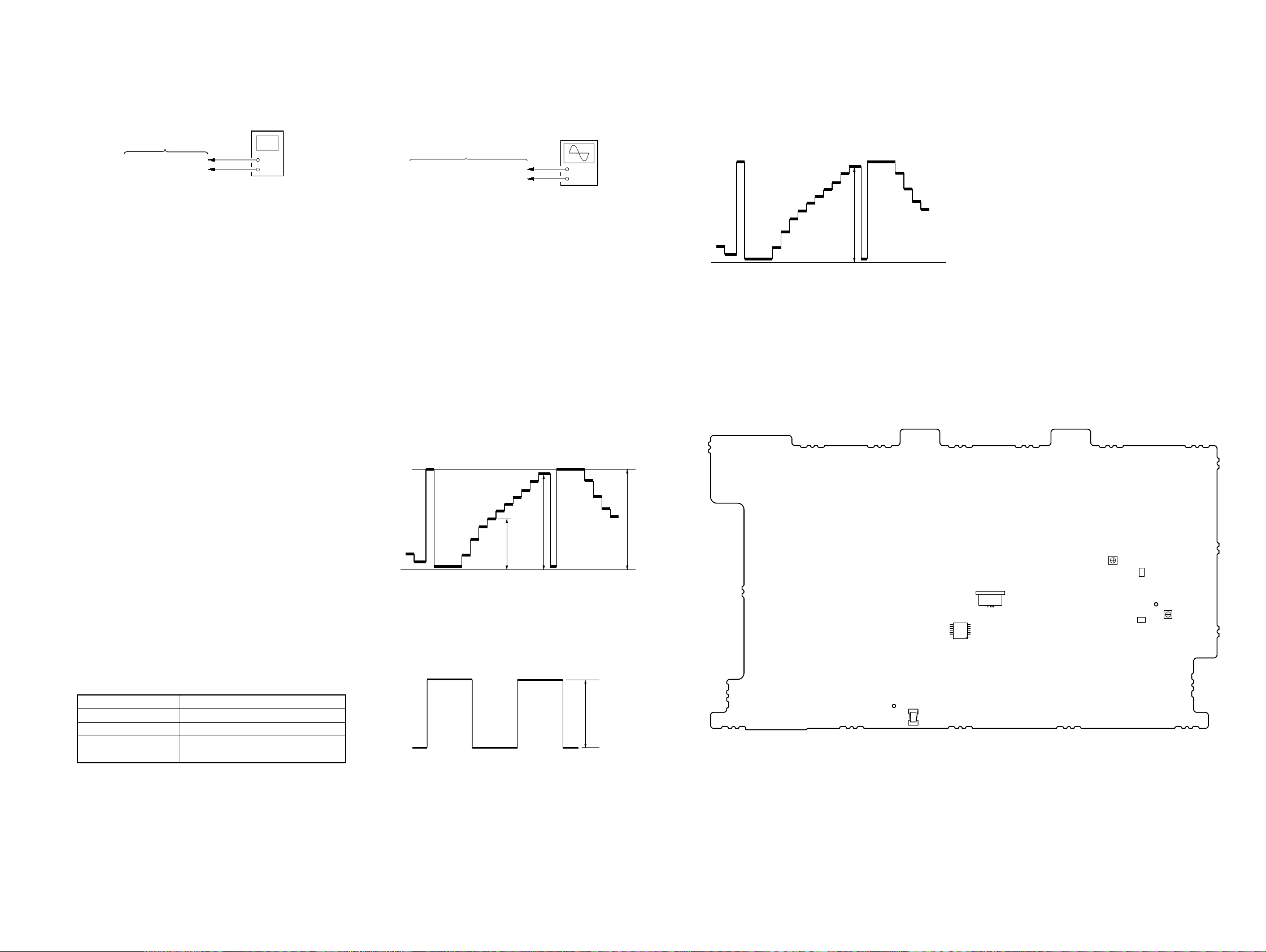
MONITOR ADJUSTMENT
Setting:
oscilloscop
(DC range)
LCD board
IC1033 pin
qs
/CN1010 pin
U7
1
Procedure:
1. Connect a TV SSG to the AUX3 jack on the MAIN board.
2. Input 10 steps signal (chroma off, NTSC composite video)
from AUX3 jack on the MAIN board.
3. Connect an oscilloscope to the IC1033 pin qs and U7 on the
LCD board.
4. Set the test mode and press the [SEEK +]/[SEEK ---] button to
select the “RGB AMP.”.
5. Adjust the [VOL +]/[VOL ---] button so that the A level of the
waveform on the oscilloscope becomes 5.0 V ± 0.05 V. (Vb-b
adjustment)
6. Press the [SEEK +]/[SEEK ---] button to select the “Cont-V ideo”.
7. Adjust the [VOL +]/[VOL ---] button so that the B level of the
waveform on the oscilloscope becomes 4.8 V to 4.9 V . (Vb-w
adjustment)
8. Press the [SEEK +]/[SEEK ---] button to select the “Bright ”.
9. Adjust the [VOL +]/[VOL ---] button so that the C level of the
waveform on the oscilloscope becomes 2.1 V ± 0.05 V.
(Gamma adjustment)
10. Repeat the step 6 to 9 several times to become specified voltage.
+
–
17. Adjust the [VOL +]/[VOL ---] button so that the E level of the
waveform on the oscilloscope becomes 4.8 V ± 0.05 V . (D VD
adjustment)
18. Press the [OFF] button to write the adjustment v alue and release
the test mode.
GND
E
Connection Location: LCD board
FLICKER ADJUSTMENT
Adjustment and Connection Location:
Procedure:
1. Connect a TV SSG to the AUX3 jack on the MAIN board.
2. Input 10 steps signal (chroma off, NTSC composite video)
from AUX3 jack on the MAIN board.
3. Set the test mode and press the [SEEK +]/[SEEK ---] button to
select the “Flicker-NTSC”. (Afterwards, hold the state for 30
minutes or more)
4. Give a shock to the set, adjust the [VOL +]/[VOL ---] button so
that the flicker becomes minimum in the sight.
5. Input 10 steps signal (chroma off, P AL composite video) from
AUX3 jack on the MAIN board.
6. Set the test mode and press the [SEEK +]/[SEEK ---] button to
select the “Flicker-PAL”.
7. Give a shock to the set, adjust the [VOL +]/[VOL ---] button so
that the flicker becomes minimum in the sight.
8. Press the [OFF] button to write the adjustment value and release
the test mode.
SETTING THE TEST MODE
Procedure:
1. Turn the power on and press the [OPEN/CLOSE] button to open
the monitor.
2. Press the [OFF] button to set the OFF state.
3. Press the [SOURCE] and [SEEK +] buttons simultaneously for
several seconds.
4. When test mode is activated, “Picture” is displayed on the
monitor and segments of sub display all lit.
BASIC OPERATIONS OF THE TEST MODE
The functions of these buttons are as follows.
[SEEK +]/[SEEK ---] button Proceeding and return of adjustment item*
[VOL +]/[VOL ---] button Increase and decrease of adjustment value
[OFF] button
* The adjustment item switches as follows whenever the [SEEK +]/[SEEK ---]
button is pressed; ··· ↔ Picture ↔ Color ↔ Tint(HUE) ↔ Phase ↔ Cont-
Video ↔ Cont-RGB1 ↔ Cont-RGB2 ↔ GAMMA 1 ↔ GAMMA 2↔
RGB AMP . ↔ Bright ↔ SUB-Bright-R ↔ SUB-Bright-B ↔ COM-Amp.
↔ Flicker-NTSC ↔ Flicker-PAL ↔ ···.
Button Function
Writing of adjustment value and releasing
of test mode
GND
ABC
11. Connect an oscilloscope to the CN1010 1 pin and U7 on the
LCD board.
12. Press the [SEEK +]/[SEEK ---] button to select the “COM-Amp.”.
13. Adjust the [VOL +]/[VOL ---] button so that the D level of the
waveform on the oscilloscope becomes 5.6 V ± 0.1 V. (VCOM
adjustment)
D
14. Insert the DVD test disc and play the track No. 5.
DVD test disc:
HLX-504 (Part No.: J-6090-088-A) (single layer) (NTSC)
HLX-505 (Part No.: J-6090-089-A) (dual layer) (NTSC)
HLX-506 (Part No.: J-6090-077-A) (single layer) (PAL)
HLX-507 (Part No.: J-6090-078-A) (dual layer) (PAL)
15. Connect an oscilloscope to the IC1033 pin qs and U7 on the
LCD board.
16. Press the [SEEK +]/[SEEK ---] button to select the “Cont-RGB1”.
XAV-A1
2323
XAV-A1
SECTION 5
DIAGRAMS
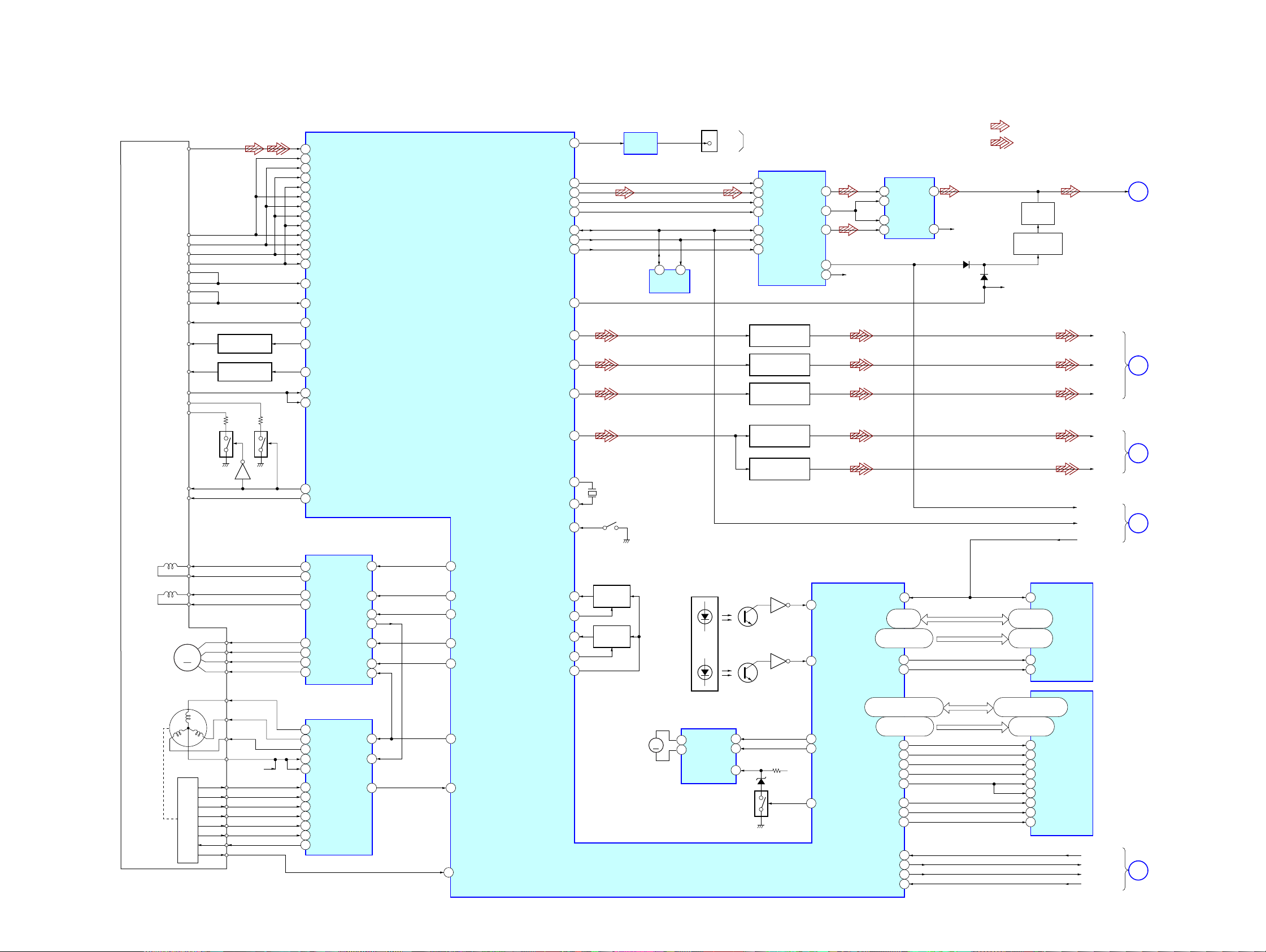
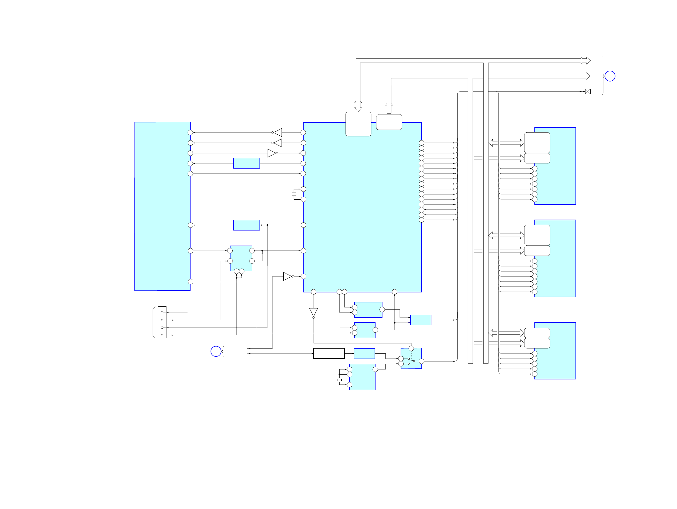
5-1. BLOCK DIAGRAM – SERVO Section –
DVD CHASSIS
FOCUS
COIL
TRACKING
COIL
ASSY
(SLED)
A/a
B/b
C/c
D/d
VREF
LD-CD
LD-DVD
CD-VR
DVD-VR
SW1
SW2
RF
E1
E2
F1
F2
PD
F+
F-
T+
T-
M
M
DVD/CD
SWITCH
(DVD)
Q1105
LD DRIVER (CD)
Q1110
LD DRIVER (DVD)
Q1111
Q1106
SL1+
SL1SL2+
SL2-
60 XCDRF
49 XCD_A
48 XCD_B
47 XCD_C
46 XCD_D
54 XDVD_A
53 XDVD_B
XDVD_C
52
XDVD_D
51
XDPD_A
58
XDPD_B
57
56
XDPD_C
55
XDPD_D
45 XCD_E
44 XCD_F
34 XVREF21
40 XCDLD
39 XDVDLD
36 XDVDPD
38 XCDPD
DVD/CD
SWITCH
(CD)
Q1104
17 CD_DVDCT
144 GAINSW
FOCUS/TRACKING COIL DRIVE,
SLED MOTOR DRIVE
IC1101
11 V02+
10 V02-
17 V03+
16 V03-
13 V01+
12 V0114 V04+
15 V04-
• SIGNAL PATH
CS581
1
SENSOR LED
BLOCK
DOUT
NC
LOW-PASS FILTER
LOW-PASS FILTER
LOW-PASS FILTER
LOW-PASS FILTER
LOW-PASS FILTER
DISC IN
DETECT
Q1102
DISC SIZE
DETECT
Q1101
D/A
CONVERTER
IC1207
Q1205
Q1207
Q1203
Q1206
Q1208
Q1108
Q1107
7 6 7
10
8 2
12
ZEROL
ZEROR
18
20
11
SENS-A
SENS-B
R-CH
XCRESETJ
XROMWEJ
XROMOEJ
LOW-PASS
5
FILTER
IC1206
3
CVBS
CVBS2
132
93,95,
97-102
131,129-127,125,
123-116,114-108
105 11
103 28
1
R-CH
D1203
ROMDATA0-7
ROMAD0-19
X1101
27MHz
MUTING
MUTING
BUFFER
IC631
EEPROM
IC1104
(CHUCKING)
5 6
S1101
211
XIECDATA
LRCLK
204 3
XLRCLK
XASDA3
XBCLK
XDASCLK
XIIC-DA/DAC MD/DVDTXD
XIIC-SCL/DAC MC
DAC CS
DMUTE
TVDAC2
CD/DVD DSP,
MPEG DECODER
IC1102
76 XFOCUS5IN2
77 XTRACKING23IN3
22OPOUT
3VIN1
25VIN4
8STBY
82 SPINDL21OP-
80 XSLEGP
79
XSLEGN
TVDAC0
TVDAC3
TVDAV1
XOUT
XIN-XCLK
SWITCH-C
XTDO
TXD
XTDI
XTMS
XTCK
SER3
205 2
BCLK
203 1
DASCLK
201 16
XSDA/MD/TXD
196 13
SCL/MC
195 14
DAC_CS
198 15
199
3
8
2
7
136
135
140
190
134
194
193
192
D1203
MUTE CONTROL
R-CH
29,31,33,35,
38,40,42,44
45,25-18,
8-1,48,17-16
: DVD/CD (AUDIO)
: DVD (VIDEO)
MUTING
Q1202
Q1211,1212
FLASH MEMORY
IC1106
RESET
12
WE
OE
DVD_R
DVD_G
DVD_B
DVD_CV
S-Y
ZEROL
MPEG_DI
CPURST
DVD_L
A
B
C
D
(Page 25)
(Page 27)
(Page 25)
(Page 27)
XAV-A1
(SPINDLE)
U
V
W
COM
FG
5VCC
HU+
HUHV+
HVHW+
HWVM
INSIDE
MOTOR DRIVE
5A1
3A2
2A3
23 VM
22 VCC
7H1+
8H1-
9H2+
10 H211 H3+
12 H313 VH
SPINDLE
IC1301
LOADING
MOTOR DRIVER
IC1103
VD33A
114
125
141
LOAD+
LOAD-
LOADUP
20PS
18ECR
22 DRVSB
XSFGN
8521FG
15 INSIDE SW
M1100
(LOADING)
MM
7
LM–
LD-
VR
VOLTAGE
CONTROL
Q1103
6
DZ1101
LD+
LM+
1
163,164,166-169,171,173,
154-157,159-162
177-174,152-148,
146,178,182
XBA0
180 20
XBA1
181 21
XRASJ
183 18
XCASJ
184 17
XDQM
186 15
XWEJ
185 16
187 19
XCSJ
XDMCLK
143 38
13
EJECT
200
DVD STB
138
XTOCK
SYS CPU TXD
197
MD0-15
MA0-17
2,4,5,7,8,10,11,13,
42,44,45,47,48,50,51,53
23-26,29-34,
22,35
BA0
BA1
RAS
CAS
LDQM
39
UDQM
WE
CS
CLK
SD-RAM
IC1105
DVDEJECT
MPEG_REQ
MPEG_CLK
MPEG_DO
P
(Page 27)
2424
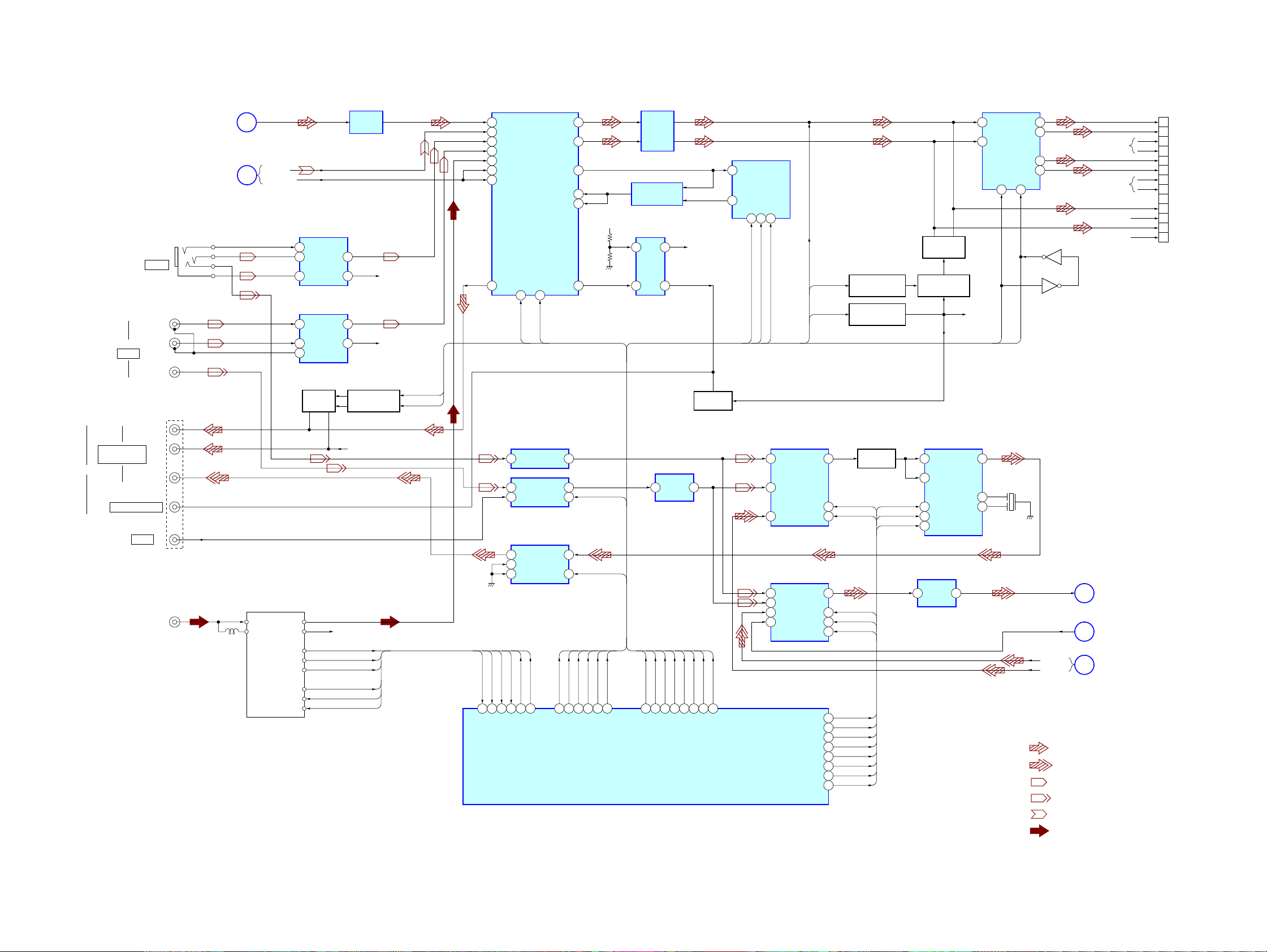
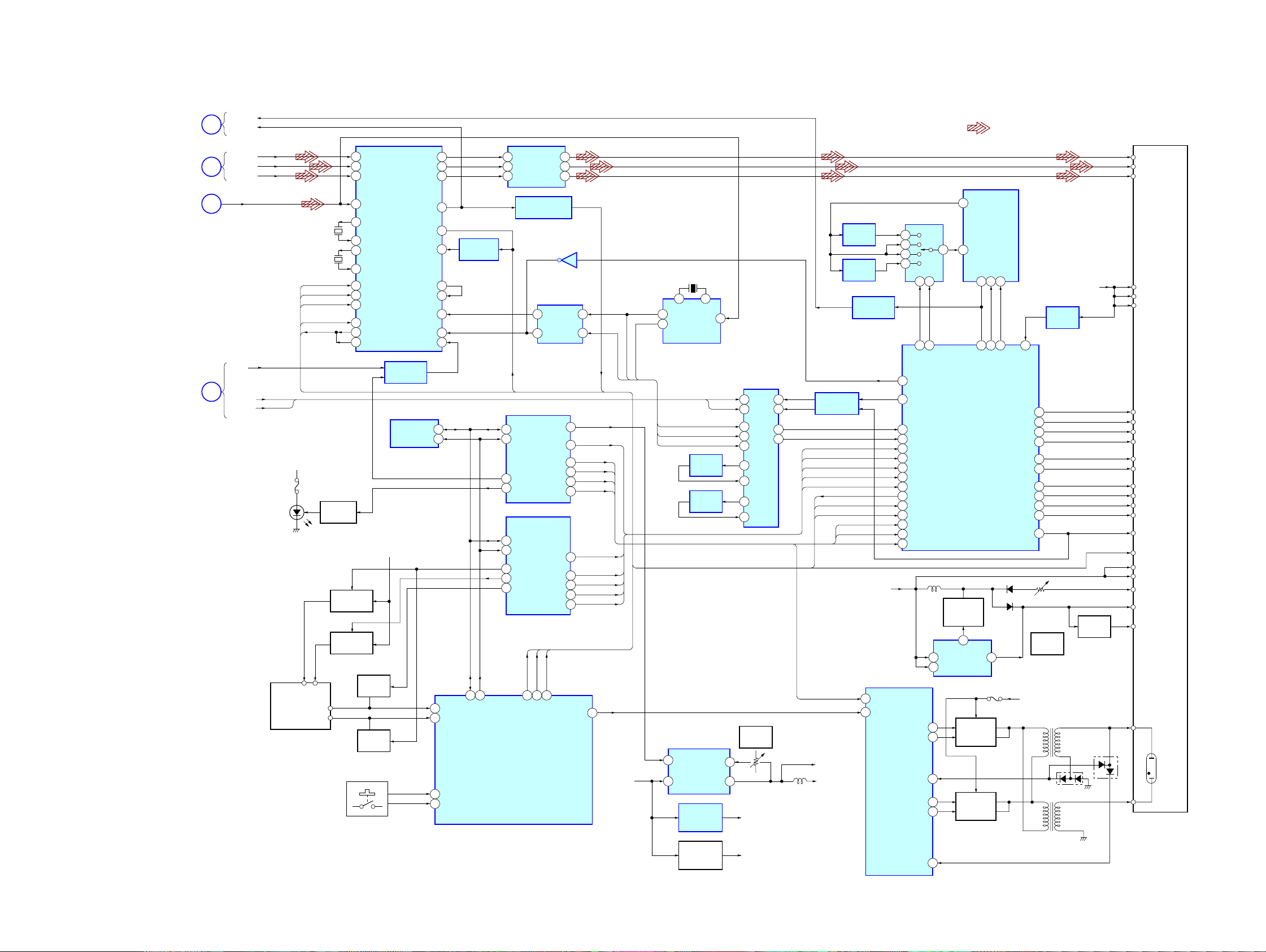
5-2. BLOCK DIAGRAM – AUDIO/VIDEO Section –
XAV-A1
CP451
CP402
AUX 2
REAR MONITOR
OUT
SUB OUT (MONO)
CP401
AUX 3
(CAMERA)
CP203
(ANTENNA IN)
JAK1001
A/V IN
(VIDEO)
(VIDEO)
CP1(1/3)
15
16
3
4
13
14
1
2
5
17
7
19
FL+
FLFR+
FRRL+
RLRR+
RR-
RCA-FL
RCA-FR
RCA-RL
RCA-RR
(Page 24)
(Page 29)
(L)
(R)
(L)
(R)
REAR_CV
A
F
AM/FM TUNER
AM IN
DVD_L
EXT_L
EXT_GND
FRONT_L
FRONT_R
AUX_CV
AUX2_CV
TU251
AM AGC
ST-LANP
LCHFM IN
RCH
VSW
SDA
SCL
2
AMP
5
IC611
3
3
AMP
IC661
5
2
MUTING
Q402
DO
7
1
1
7
MUTING DRIVER
R-CH
R-CH
RA_SM
AM_AGC
RA_ST
RA_SD
RA_SDA
RA_SCL
AMP
IC681
AUX_L
AUX2_L
Q403,404
R-CH
R-CH
PREL-ATT
PRER-ATT
RA-L
DVDL
9 39
EXT_L
3
AUX_L
11
AUX2_L
13
RA_L
7
4
5
INPUT SELECT,
ELECTRICAL VOLUME
IC401
POUT-
LCH
15
43 42
VR_CLK
VR_DATA
VIDEO AMP
4 2 3
IC305
1
AUX2BCOUT
3 2
VIDEO SWITCH
IC310
7
OUT
2
SW1
5
VIDEO SWITCH
IC309
RA_ST
RA_SD
RA_SM
AM_AGC
143 111 110 112 107
138
RA_SM
AM_AGC
RA_SDA
39 37 36 38
RA_ST
RA_SD
RA_SDA
RA_SCL
RA_SCL
SW1
IN1
MUTE
37
31
33
35
SUB
29
OUT
7
1
4
PREL_ATT
PRER_ATT
438485 42 28 29
PREL_ATT
PRER_ATT
VR-EQL
EQ-VRL
VR_CLK
VR_DATA
VR_CLK
VR_DATA
VA
BC/AUX2
RMMUTE
EQ_CLK
EQ_DATA
EQ_CLK
EQ_DATA
SYSTEM CONTROLLER
EQUALIZER AMP
5
BUFFER
IC461
3
EQ_CE
27
IC101(1/5)
AMP
IC502
IC460
7
1
VIDEO
AMP
4 2
IC306
BEEP
L_ATT
ATT_ON
56
88
BEEP
L_ATT
EQ_CE
ATT_ON
AV4VREF
STBY1
AFMUTE
STBY1
MUTING
Q401
BC/AUX2
96
AFMUTE
BC/AUX2
RMMUTE
RMMUTE
60
59
EQUALIZER
IC451
26 25 27
EQ_DATA
EQ_CLK
EQ_CE
1
5 4
6 14
1
8
10
BEEP
VIDEO SWITCH
IC307
AUX1
OUT
REAR
SW1
DVD SW2
VIDEO SWITCH
IC303
AUX1 OUT
REAR
DVD
F_AUX
RMSW1
RMSW2
OSD_SIN
OSD_SCLK
OSD_/CS
VSW1
VSW2
VMUTE
L_ATT
ATT_ON
MUTING CONTROL
MUTING CONTROL
7
RMSW1 OSD_SIN
2
RMSW2
VSW1
3
VSW2
4
VMUTE
5
RMSW1
105
RMSW2
106
OSD_SIN
83
OSD_SCLK
82
OSD_/CS
81
VSW1
93
VSW2
94
VMUTE
95
Q508
Q501,506
BUFFER
Q351
OSD_SCLK
OSD_/CS
MUTING
Q502,503
MUTING DRIVER
Q510
CIN
15
SYNC IN
17
OSD
DRIVER
11
IC308
10
9
VIDEO
AMP
4 2
IC304
12 5
11
R-CH
C OUT
13
2
3
3
POWER
AMP
224
AFMUTE
9
7
C-VIDEO
Q2_CSYNC
S-Y
DVD-CV
E
G
C
IC555
STBY1
X301
7.159MHz
• R-ch is omitted due to same as L-ch.
• SIGNAL PATH
: DVD/CD (AUDIO)
: DVD (VIDEO)
: AUX IN (AUDIO)
R-CH
R-CH
R-CH
R-CH
(Page 28)
(Page 27)
(Page 24)
: AUX IN (VIDEO)
: BUS IN (AUDIO)
: TUNER
XAV-A1
2525
XAV-A1
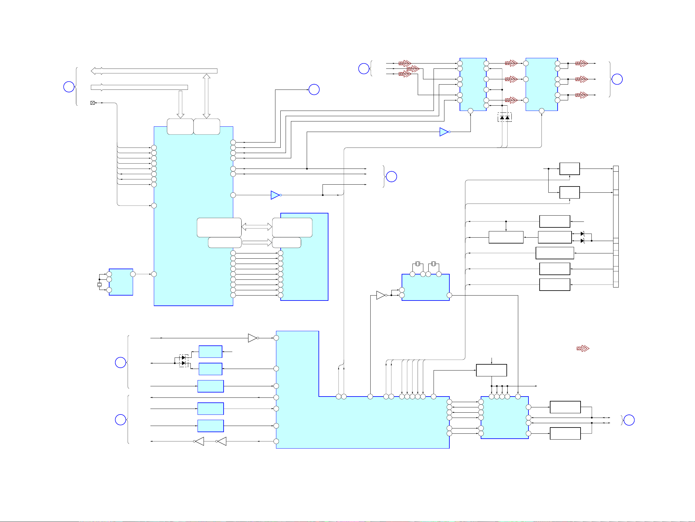
5-3. BLOCK DIAGRAM – CPU Section –
NV_OPENING
SH_MAIN_5
MAIN_SH_5
SYSTEM
CONTROLLER
IC101(2/5)
NAVI_OFF
ACCOFF
SH_MAIN2
MAIN2_SH
/NV_RST
DATA BUS
DATA BUS
ADDRESS BUS
SD0-31
44-40,38,
36-28,26,
100
130
65
GPS-MAIN
SWITCH
IC808
5
2
7 1
LEVEL SHIFT
IC108
LEVEL SHIFT
IC107
62
61
59
60
101
Q801
Q804
Q802
X801
14.7456MHz
3
6
94
107
106
140
145
132
131
142
146
Q805
162
100 133 134
24-22,20,
18-14,12,
10-5
CPU
IC801
SA1-22
46-48,50,
52-60,62,
64-70,72,
RST_SH
165
/RD
/WE0
/WE1
/WE2
/WE3
RD/WR
/FCS
/CS3
/CS_Q2UGN
/CS_Q2REG
CKIO
/RAS
/CAS
/WAIT_Q2
/IRQ_O2
FRDY
78
79
80
81
82
83
85
88
89
90
138
96
98
104
151
108
/RD
/WE0
/WE1
/WE2
/WE3
RD/WR
/FCS
/CS3
/CS_Q2UGN
/CS_Q2REG
CKIO
/RAS
/CAS
/WAIT_Q2
/IRQ_O2
FRDY
SD0-15
SA2-15
/WE0
RD/WR
/CAS
/RAS
CKIO
/CS3
/WE1
SD16-31
SA2-15
/WE2
RD/WR
/CAS
/RAS
CKIO
/CS3
/WE3
2,4,5,7,8,
10,11,13,,42
44,45,47,48,
50,51,53,90
23-26,29-34,
22,35,20,21
15
16
17
18
38
19
39
2,4,5,7,8,
10,11,13,,42
44,45,47,48,
50,51,53,90
23-26,29-34,
22,35,20,21
15
16
17
18
38
19
39
SD-RAM
IC841
SD-RAM
IC842
DATA
ADD
CTL
I
(Page 27)
CP5
5
3
NC
2
1
GPS/MAIN
MAIN_SH
SH_MAIN
VDD
(Page 28)
Q803
LVCC
PAL/NTSC
H
CLK1
OSD CLOCK AMP
Q921
X842
9.6MHz
2
1
1
3
3
2
GENERATOR
6
WATCH-DOG
TIMER
IC802
RESET
IC805
BUFFER
IC923
CLOCK
IC897
4
AND GATE
IC804
4
5
7
5
6
CLOCK SELECT
1
IC921
/RST_3
Q2CLK1
SD0-15
SA1-22
/WE0
/RES_3
FRDY
/FCS
/RD
29-36,
38-45
25-18,8-1,48,
17,16,9,10,13
11
12
15
26
28
FLASH MEMORY
IC843
XAV-A1
2626
5-4. BLOCK DIAGRAM – GRAPHIC/BUS CONTROL Section –
XAV-A1
(Page 26)
B
DVD_R
DVD_G
/HSYNC
/VSYNC
CDE
DVD_B
Q655
Q2_R
Q2_G
Q2_B
(Page 28)
J
X651
15.7MHz
1 12
0Y
0X
9
A
B YCOM
10 3
OSC SWITCH
IC652
X652
16MHz
11 4
3X
3Y
CLOCK
IC896
DATA BUS
ADDRESS BUS
/CS_Q2UGM
/CS_Q2REG
/RD
/WE0
/WE1
/WAIT_Q2
/IRQ_Q2
/RST_3
Q2 CLK1
Q2_CSYNC
SA1 – 22
18 – 24,26,
28 – 37,39,
41 – 43
163
164
165
166
169
171
44
CONTROLLER
138
SD0 – 15
173 – 176,1,2,
4,6 – 11,13,
15,16
GRAPHIC
IC861
54,55,57,59,60,62,63,65,
76,74,72 – 67,113,112,
110,108 – 104,114,116,117,
119,121 – 123,124
103,101,99,98,95,94,
92,90 – 85
Q2_CSYNC
157
Q2_R
145162
Q2_G
146
Q2_B
148
/HSYNC
140
/VSYNC
142
IC922
161
MD0 – 31
MA0 – 12
83
81
80
79
78485
77
49
96
97
UDQM1
UDQM0
LDQM1
LDQM0
/MWE
/MCS
MCLK
/MRAS
/MCAS
2,4,5,7,8,10,11,13,
74,76,77,79,80,82,83,85,
31,32,34,36,37,39,40,42,
45,47,48,50,51,53,54,56
25 – 27,60 – 66,
24,22,23
59
28
71
16
17
20
68
19
18
GRAPHIC
MEMORY
(D-RAM)
IC901
G
DATA
ADD
I
CTL
3
2
X896
32.72MHz
GENERATOR
6
(Page 24)
(Page 25)
/HSYNC
CDE
IC208
1 3
16
14
11
8
9
2
VIDEO
5
SELECT
IC301
12
6
7
10 1
D301
CDE
RGB_NAVI
PANT+B
RCA+B
BATT
CE
ILMIN
/RVS
PARKIN
ACCESSORY DETECT
Q1
2
VIDEO
4
AMP
IC302
7
RGB_MUTE
ACC
BATTERY DETECT
ACCESSORY CHECK
ILLUMINATION DETECT
REVERSE DETECT
PARKING DETECT
Q6,7
Q2,3
Q9
Q17
Q16
15
14
13
12
10
9
B+ SWITCH
B+ SWITCH
Q11,12
Q13,14
DZ5
DZ6
LCD_R
K
CP1(2/3)
8
9
10
22
21
20
(Page 28)
P.ANT
RCA
ACC
ILM
REV
PARKIN
LCD_G
LCD_B
PANT
RCA
BU
ACC-IN
ILM
REV
PARKIN
XAV-A1
(Page 24)
(Page 24)
Q102
/ZEROL
ZERO L
LEVEL SHIFT
LEVEL SHIFT
LEVEL SHIFT
Q1109
RESET
IC1204
BUFFER
IC1205
IC106
IC109
IC105
D1201
CPURST
D
MPEG_DI
MPEG_DO
MPEG_REQ
P
MPEG_CLK
DVDEJECT
VD33
Q1112
54
48
49
50
75
51
102
MPEG_RST
MPEG_DI
MPEG_DO
MPEG_REQ
MPEG_CLK
DVD_EJECT
RGB_NAVI
RGB_MUTE
108 109 119 131 120
SYSTEM CONTROLLER
67
IC101(3/5)
OSC_SW
PANT+B
RCA+B
BATTCEILMIN
/RVS
18
1992 89 70 1 11 10 1324
PARKIN
J1850_PWR
72
71
74
68
69
73
RXD
TXD
INT
RES
AD
SCLK/PA
VDD
B+ SWITCH
Q653,654
20
21 5
22
23
15
16
J-BUS
DRIVER
IC651
• SIGNAL PATH
: DVD/CD (VIDEO)
BUS5V
BUS DRIVER
Q651
4
3
1
BUS DRIVER
Q652
BUS+
BUS-
L
(Page 29)
2727
XAV-A1
5-5. BLOCK DIAGRAM – MONITOR Section –
(Page 26)
(Page 27)
(Page 25)
(Page 27)
H
PAL/NTSC
K
C-VIDEO
E
CDE
J
/HSYNC
/VSYNC
D1201 – D1205,
LED1001 – LED1003
(KEY ILLUMINATION)
CLK1
LCD_R
/HSYNC
/VSYNC
X1002
3.579545MHz
X1001
4.433619MHz
LCD-DATA
LCD-CLK
LCD-CS
MUTE
VCOM
+14V
F1002
TOUCH
PANEL
S1001,1002,
S1201-1205
(MONITOR KEYS)
DIMMER
Q1003
B+ SWITCH
Q1008,1009
B+ SWITCH
15 RIN1
14 GIN1LCD_G
13 BIN1LCD_B
20 VIDEO IN
26
27
29
30
47
46
48
43 BLK IN
39 COM OUT
37 COM DC
Q1010
MUTING
MUTING
LCD INTERFACE
RGB SWITCH
+5.0V
Q1007
Q1011
IC1008
IC1021
EEPROM
IC1015
33 8ROUT
34 14GOUT
35 4BOUT
45N/P OUT
41COMFRP
FRP DRIVER
42FRP
IC1020
5HFILOUT
4SYNC IN1
3SYNC IN2 1
1HYS IN
12SW1
PCA
5 4
6 2
SCL1
SDA1
ILLMOUT
132
133
17
141
RGBSW
TP-Y
TPCONT
TP-X
X-AD
Y-AD
KEY2
KEY3
17
20
4
2
12
11
10
31
SCL1
SDA1
SYSTEM CONTROLLER
IC101 (4/5)
VIDEO
AMP
IC1033
NTSC/PAL SELECT
IC1018
SYNC
SWITCH
IC1031
6
I/O
EXPANDER
IC1011
I/O
EXPANDER
IC1012
11532
114 113
LCD-CS
LCD-CLK
LCD-DATA
6
12
10
IC1030
7 5
5
/N/P
RESET1
10
HD2
16
LIGHT
19
MODE0
11
MODE1
12
MODE2
14
SYNC_SW
14
VD2
20
HD3
19
HD1
16
HD0
17
4
DIMMER
SYNC_SW
HSC
VSC
+14V
HSC
VHC
4
HSC
VSC
SYNC SW
7
1
X1003
503.5kHz
SYNC
SEPARATOR
IC1010
BUFFER
IC1022
BUFFER
IC1023
DC/DC
CONVERTER
IC1014
EN
VIN
+5V
REGULATOR
IC1034
+7V
REGULATOR
109
2
/HSYNC
/VSYNC
INV
SW
SYNC SWITCH
4 11
9
5
14
1
10
13
3
6
SVR1001
VOLTAGE
(+5.4V)
5
2
+5.0V
+7.0V
IC1019
/VSYNC
SYNC DRIVER
/HSYNC
2
/HSC
7 14
/VSC
12 15
IC1017
VD2
HD3
HD2
HD1
HD0
MUTE
PCA
/N/P
MODE0
MODE1
MODE2
LIGHT
+5.4V
+5.0V
AMP
IC1003
AMP
IC1004
1/2 DIVIDER
IC1016
3
14
+5.4V
DC/DC
CONVERTER
IC1007
ENA
DIM
INVERTER
CONTROLLER
IC1009
PLL SELECT
IC1006
12
14
15
11
HSCO
39
VSCO
38
/HSC
/VSC
6
VD2
77
HD3
76
HD2
75
HD1
74
HD0
36
MUTE
34
PCA
/N/P
49
56
MODE0
54
MODE1
MODE2
50
NDRV_B
PDRV_A
PDRV_C
NDRV_D
OVP
AB
10 9
69 71
VCOS1
FB
13
VCOS2
2
3
20
19
9
11
12
2
6
12
TIMING
CONTROLLER
SWITCHING
REGULATOR
Q1002
5
VDD
CE
SWITCHING
REGULATOR
SWITCHING
REGULATOR
IC1001
• SIGNAL PATH
: DVD/CD (VIDEO)
PFDO
PLL
IC1002
VCOI
VCOO
FINA
FINB
3 4
17 43542
PLS
PLO
DCK1
EXT
VOUT
1
F1001
Q1004
Q1005
53
POC
VSP1
VSP2
VOE
UD
VCK
HCK
HSP1
HSP2
RL
RESET
DLP
+14V
TRANSFORMER
TRANSFORMER
24
25
23
63
26
32
30
31
62
28
29
SVR1002
SVR1002
VOLTAGE
(–14V)
INVERTER
PT1001
INVERTER
PT1002
RESET
IC1005
D1008
+5.0V
RESET
Q1001
D1007
VR
VG
VB
LCD UNIT
VSP1
VSP2
VOE
UD
VCK
HCK
HSP1
HSP2
RL
RESET
DLP
VCOM
LCD
BACK
LIGHT
XAV-A1
2828
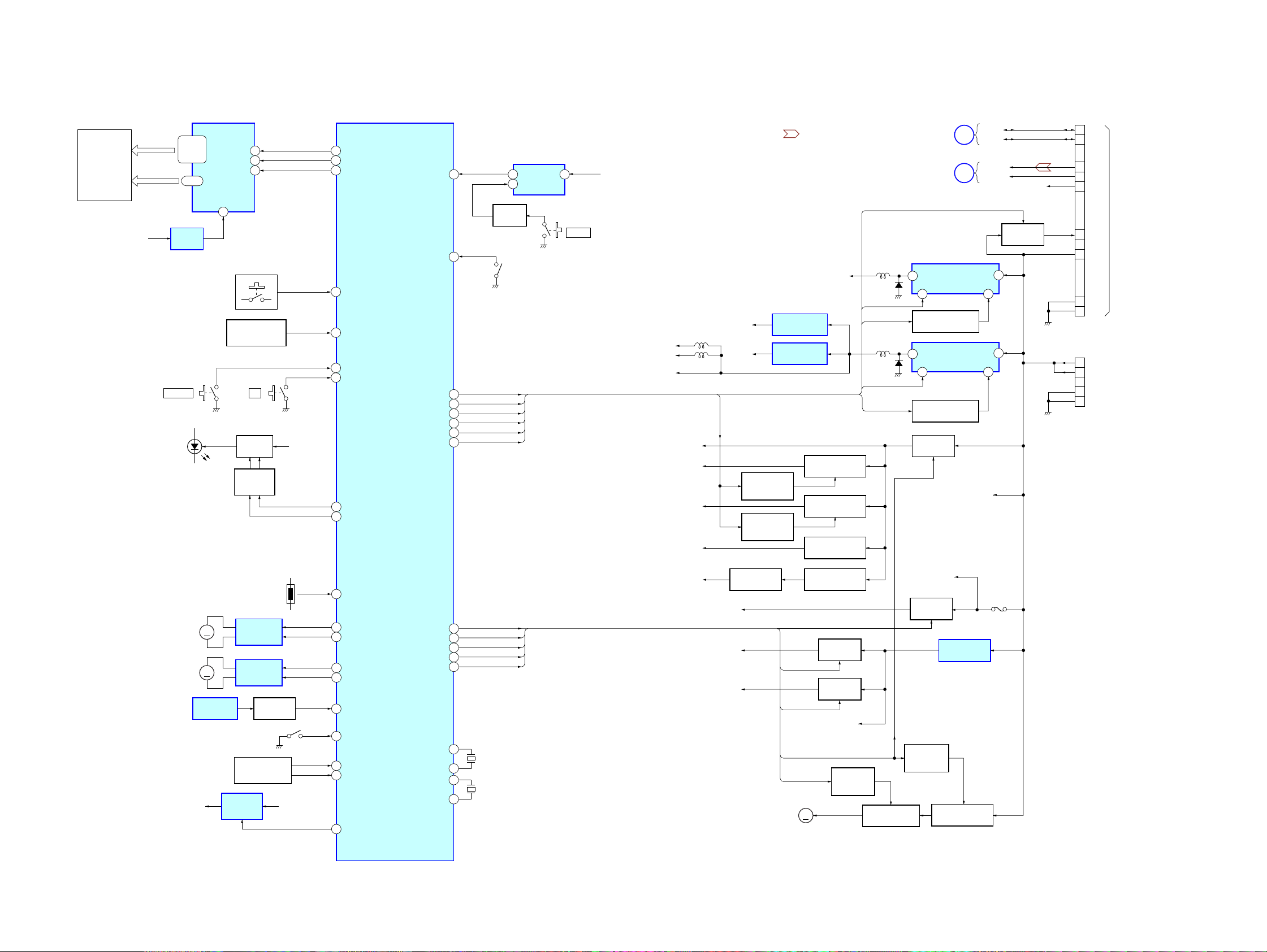
5-6. BLOCK DIAGRAM – PANEL, POWER SUPPLY Section –
XAV-A1
LIQUID CRYSTAL
DISPLAY
LCD201
SG0-31
COM1-3
AD5V
S202
SOURCE
D211 – D221,
(KEY ILLUMINATION)
D223, 234
(LCD BACK LIGHT)
23-13,
11-9,
26-34
36-38
RESET
IC202
S208 – 213
(PANEL KEYS)
LCD DRIVER
IC201
39
REMOTE CONTROL
ILM
RECEIVER
PHT201
S201
Z
DIMMER
Q31
DIMMER
CONTROL
Q20, 33
ACC
7747
7846
7945
142
20
21
76
98
99
LCDDI
LCDCL
LCDCS
KEY_LCD1
REM
PWR-KEY
DVDEJECT
ILMON
ILMOUT
PANEL_SW
SYSTEM CONTROLLER
IC101 (5/5)
FRQ_CONT1
FRQ_CONT2
RESET
EXT_PWR
DVD+B
Q2+B
RADIO_+B
CP3
R-CH
(CONTROL IN)
3
BUS+
BUS-
2
8
LCH
SGND
9
10
RCH
7
ACC
BU
6
BUSGN
4
1
GND
CP1 (2/2)
11
B.UP
B.UP
12
GND
23
24
GND
TO
CONNECTION BOX
(XA-123)
(US, Canadian model only)
or
TV TUNER UNIT
(XT-V70)
• SIGNAL PATH
: BUS IN (AUDIO)
14
144
58
45
46
116
117
66
1
5
BUFFER
Q21
(PANEL ATTACHMENT DETECT)
EXT_PWR
DVD+B
FRQ_CONT1
Q2+B
FRQ_CONT2
RA+B
RESET
IC4
2
SW602
RESET
SW601
VDD
SVD33
VA33
DVD+3V,
VD33, LVCC
ACC
+8V
+10V
EXT_PWR
DVD+5V, RF5V,
5VD, 5VCC,
A5V, DVD_VA
DVD+B
VD18
SLVCC
RA+B
VA
+1.8V REGULATOR
+1.9V REGULATOR
TUNER ON/OFF
SWITCH
Q22
TUNER ON/OFF
SWITCH
Q23
IC1202
IC23
+10V REGULATOR
+8V REGULATOR
Q26
Q27
+9V REGULATOR
Q28
FRQ_CONT1
Q2+B
FRQ_CONT2
(Page 27)
(Page 25)
D33
2
7 3
EN/SYNC
FREQUENCY CONTROL
D34
2
7 3
EN/SYNC
FREQUENCY CONTROL
B+ SWITCH
Q25,36
DC/DC
CONVERTER
IC21
Q34
DC/DC
CONVERTER
IC22
Q35
BUS+
L
BUS-
EXT_L
F
EXT_GND
ACC SWITCH
Q641,642
1
VINSW
RT
1
VINSW
RT
BU
M1
(SLIDE)
M2
(ANGLE)
+7V
(SLIDER)
MM
MM
SLIDE DETECT
PH1
REGULATOR
TH1
SLIDE MOTOR
DRIVE
IC2
ANGLE MOTOR
DRIVE
IC3
LEVEL SHIFT
Q1
S2
(CLOSE)
OPEN/CLOSE
MECHANISM DECK
(DB-M01)
+7V
IC1
LCD+BU
135
TEMP_SENSOR
121
SL-MOTER+
122
SL-MOTOR-
127
AN-MOTOR+
128
AN-MOTOR-
125
PHOTO_SENSOR
126
SL-CLOSE_SW
124
ANGLE0_SW
129
ROTARY_SENSOR
123
MOTOR_ON
AV5V_ON
KEY_PWR
FAN_CONT
LCD+B
STBY2
V5V
52
3
97
90
118
12
13
15
16
AV5V_ON
KEY_PWR
FAN_CONT
LCD+B
STBY2
X101
4MHz
X102
32.768kHz
+5V REGULATOR
LCD+14V
AV5V
AD5V
Q30
LCD+B
AV5V_ON
KEY_PWR
STBY2
FAN_CONT
M40
(FAN)
+10V REGULATOR
Q29
B+ SWITCH
Q51
B+ SWITCH
Q52
MM
VDD
FAN MOTOR
CONTROL
Q45
FAN MOTOR DRIVE
Q44
LCD+BU
B+ SWITCH
Q24,37
REGULATOR
ON/OFF
Q41
+5V REGULATOR
IC1
+13V REGULATOR
Q43
F1
XAV-A1
2929
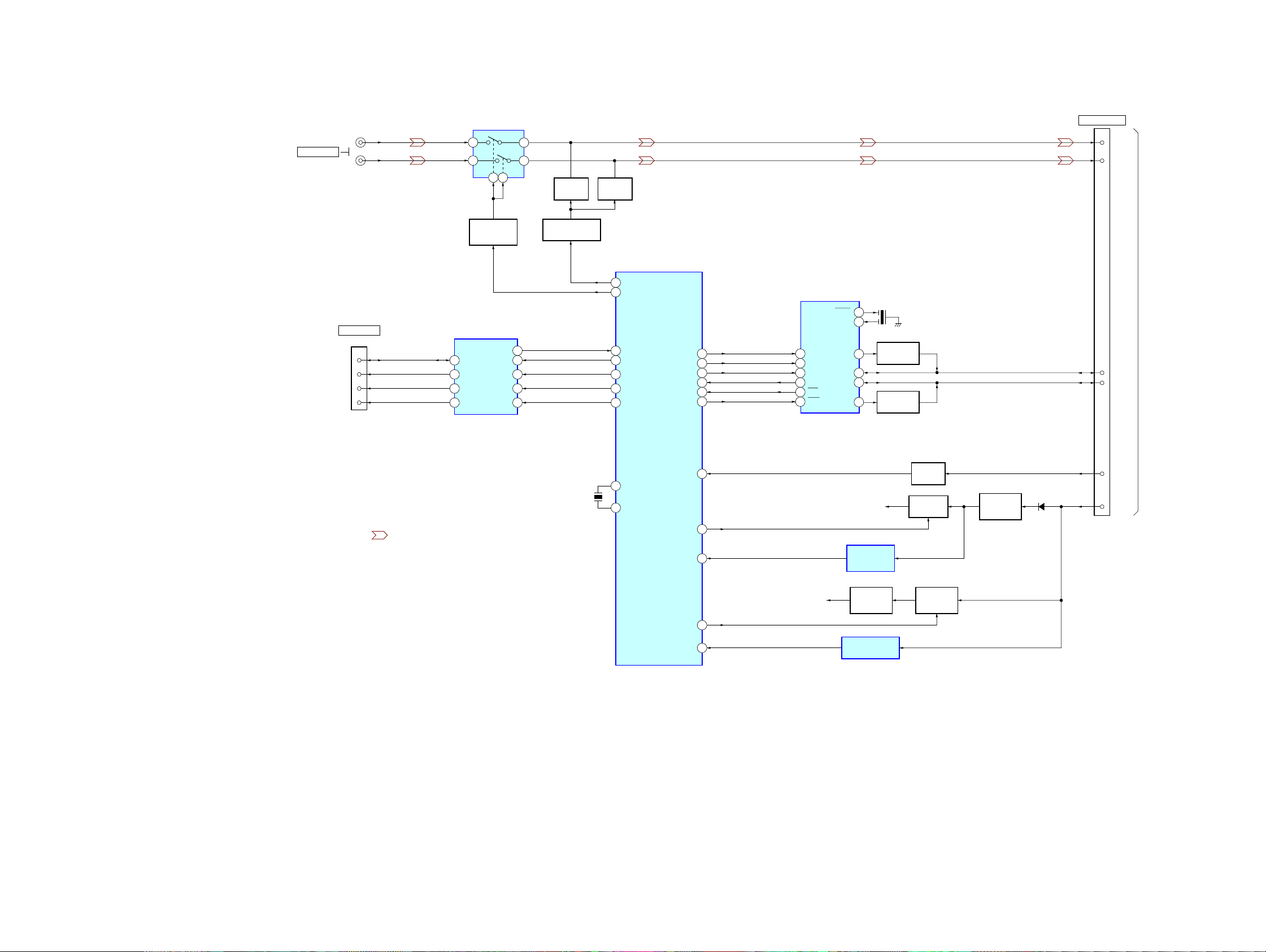
XAV-A1
5-7. BLOCK DIAGRAM – CONNECTION BOX Section – (US, Canadian, models only)
CN2
XM RADIO IN
BUS ON
(L)
(R)
XM RADIO IN
(SONY BUS)
DATA
CLK
RST
CN1
AUDIO SWITCH
IC4
1
3
AUDIO SWITCH
CONTROL
Q21, 23
SONY BUS INTERFACE
IC2
5
4
6
2
6
4
1
2
DATA
CLK
BUS ON
RST
513
DOUT
DIN
CLK IN
BUS ON
RESET
2
4
8
9
11
12
13
MUTING
Q20
MUTING CONTROL
Q22
MUTING
Q15
51
52
18
19
20
21
22
CONNECTION BOX
CONTROLLER
AFMUTE
XMPLAY
BUS SI
BUS SO
BUS CK
BUS ON
BUS RES
IC1
SCLK
TXD
RXD
INT
RES
J-BUS CONTROL
IC3
OSC1
OSC0
46
AD
47
48
49
30
50
15
AD
CLK
RX
TX
INT
RES
BO+
BUS+
BUS–
BO–
16
20
21
22
23
13
14
5
4
3
2
X2
10MHz
BUS DRIVER
BUS DRIVER
Q10
Q9
CS1
CONTROL OUT
7
LCH
9
RCH
3
BUS+
BUS–
2
TO
MAIN UNIT
(XAV-A1)
or
TV TUNER UNIT
(XT-V70)
• SIGNAL PATH
: BUS IN (AUDIO)
X1
6MHz
44
CE
41
40
45
J-BUS ON
36
RESET
AU+9V
23
ACCOUT
43
BATT
J-BUS B+
RESET SIGNAL
GENERATOR
IC6
+9V
REGULATOR
Q16
BATTERY DETECT
IC5
SWITCH
Q4, 8
B+ SWITCH
Q6, 11
ACCESSORY
SWITCH
Q7, 12
+5V
REGULATOR
Q1
D1
6
ACC
5
BU
XAV-A1
3030
 Loading...