

Sony XAV-A1, XAV-C1 Installation Manual
AV Center
2-597-872-36(1)
Installation/Connections
Установка/Подсоединения
Notice to dealers and installers
Please return this manual to the customer after the installation is completed.
Замечание для продавцов и выполняющих монтаж специалистов
Пожалуйста, после завершения установки верните настоящее руководство покупателю.
GB
RU
XAV-A1
XAV-C1
© 2005 Sony Corporation

Precautions
Unit is designed for negative ground
12 V DC systems only
The unit cannot be used in trucks or other cars
with 24 V systems. Otherwise, there is a risk of fire
and damage.
Do not disassemble or remodel the
unit
This can cause electric shock, personal injury or
fire. Do not connect any other system’s power
supply cord to this unit’s power supply cord
directly. If you are in any doubt about the safe
installation of this unit, please consult your nearest
Sony dealer.
Do not install in locations which
interfere with airbag operation
Otherwise there is a risk of accidents and injury.
Use only the specified fuse
When replacing the fuse, be sure to use only a fuse
of the same rating (ampere rating). Otherwise
there is a risk of fire.
Cautions
• Do not get the wires under a screw, or caught in
moving parts (e.g. seat railing).
• Before making connections, turn the car ignition
off to avoid short circuits.
• Connect the yellow and red power input leads
only after all other leads have been connected.
• Run all ground wires to a common ground
point.
• Be sure to insulate any loose unconnected wires
with electrical tape for safety.
Notes on the power supply cord (yellow)
• When connecting this unit in combination with
other stereo components, the connected car
circuit’s rating must be higher than the sum of
each component’s fuse.
• When no car circuits are rated high enough,
connect the unit directly to the battery.
On safety
Comply with the Traffic Laws in your country.
2

Table of Contents
Precautions...................................................................................................... 2
Parts List .......................................................................................................... 4
Connection Example....................................................................................... 5
Connecting Information ................................................................................. 6
Connecting the cords ......................................................................................................... 6
Using the tap....................................................................................................................... 6
1 Car Systems Connections.......................................................................... 7
Connecting without optional TV tuner unit .................................................................. 9
Connecting with optional TV tuner unit
2 Installing the Main Unit .......................................................................... 11
Before installation ............................................................................................................ 11
Installation procedure ..................................................................................................... 12
3 After Installation and Connections ........................................................ 14
(For Russia and Ukraine only) .................
10
3
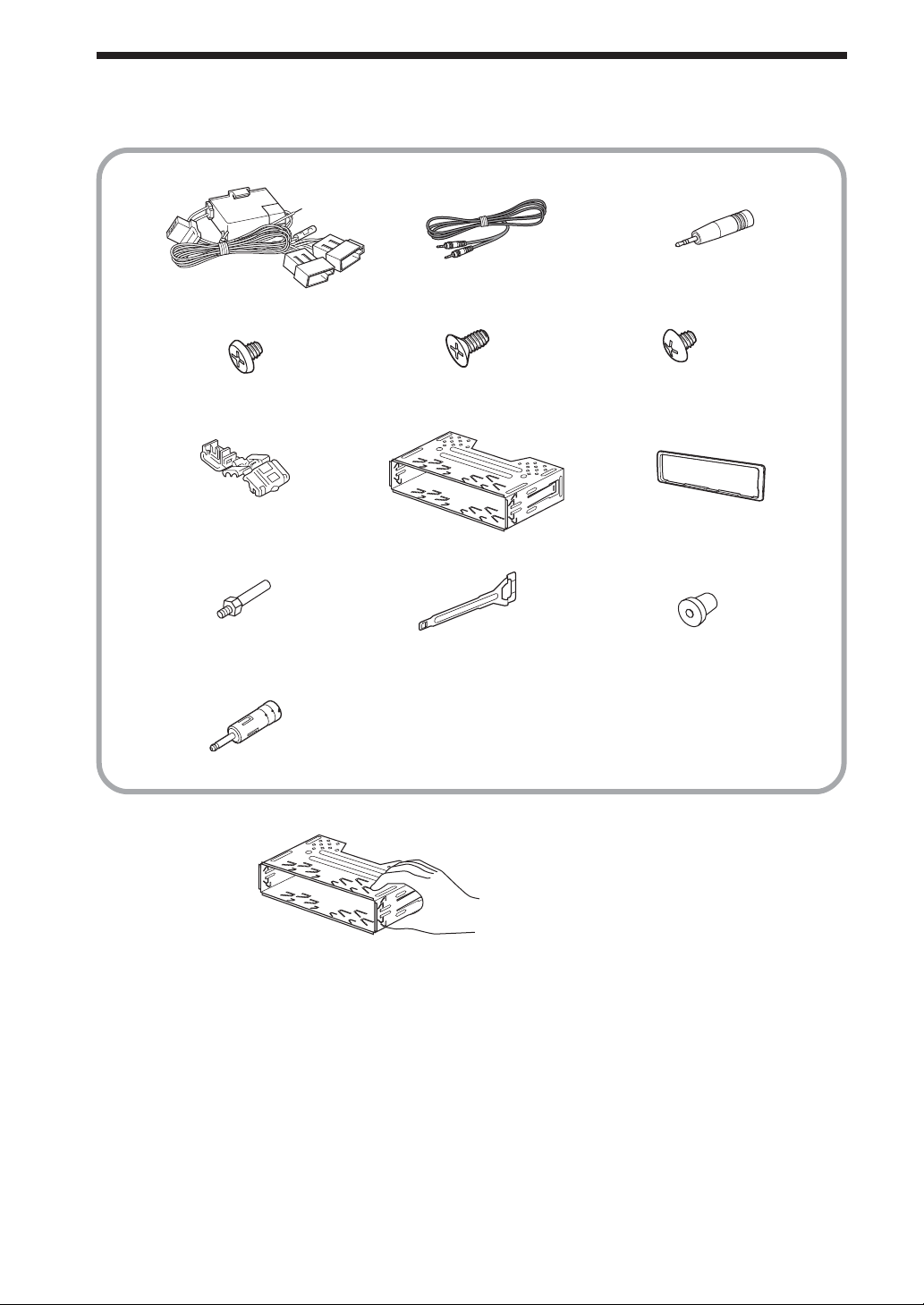
Parts List
The numbers in the list are keyed to those in the instructions.
123
456
×4
789
×2
q; qa qs
qd
CAUTION
Handle the bracket
8 carefully to avoid
injuring your fingers.
×4
×2
×4
4
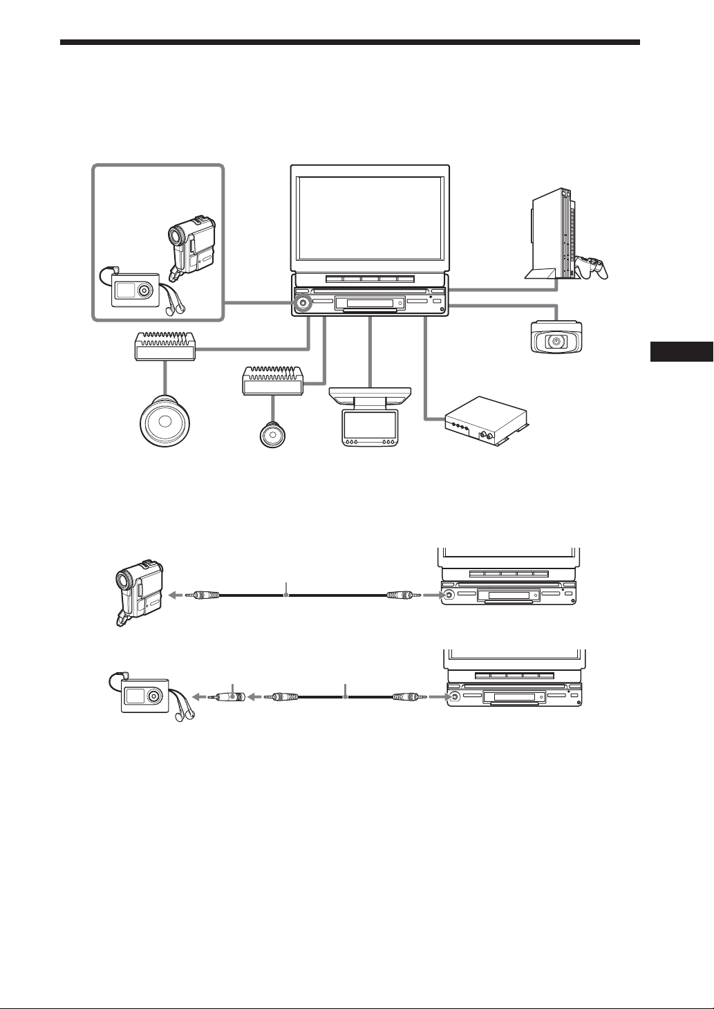
Connection Example
For details, see the section “1 Car Systems Connections” (pages 7 - 10). Be sure to refer also to the
documentation for all other components in the system.
System configuration
Walkman or
Video Camera
(optional)
A/V IN*
(Front)
(AUX 1)
Amplifier
(optional)
Amplifier
(optional)
Subwoofer
(optional)
* Connect with supplied connecting cable 2. (Use a conversion plug 3 when you connect the audio equipment.)
**For Russia and Ukraine only
When you connect the video camera
Speaker
(optional)
SUB OUT
(MONO)
AV Center XAV-A1
XAV-C1
FRONT
L/R
REAR
L/R
Rear Monitor
(optional)
REAR
MONITOR
OUT
AUX 2
AUX 3
AUX 3 and BUS
Game (optional)
Back Camera
(optional)
TV Tuner XT-V70**
(optional)
2
When you connect the audio player
23
Notes
• Be sure to connect the ground cord before connecting the amplifier.
• If you connect an optional power amplifier and do not use the built-in amplifier, the beep sound will be deactivated.
5
Connecting Information
For details, see the section “1 Car Systems Connections” (next page).
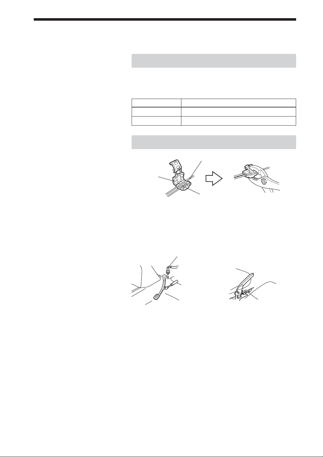
Connecting the cords
Notes
• Be sure to connect the power input
cord after all other cords are connected.
• If the parking brake switch cord is too
thin, connect the parking cord to the
parking brake switch cord directly
without using the tap.
Connect each cord using the taps. For the combination of each
cord, see the following table. Also, see the section “1 Car
Systems Connections” (next page).
Main unit side Car side
Purple/white Power terminal cord of the back lamp
Light green Parking brake switch cord
Using the tap
Parking brake switch cord
Tap 7
Parking cord
(Light green)
Connecting the parking cord
The mounting position of the parking brake switch cord depends
on your car. Refer to the system connection illustrations below
and consult your car dealer or your nearest Sony dealer for
further details.
Foot brake type Hand brake type
Parking brake
switch cord
Parking brake
switch cord
The cord for utilizing the back camera better
Purple/white cord (for the connection to the power terminal
cord of the back lamp)
If you connect the purple/white cord to the power terminal cord
of the back lamp, the image of back camera will be automatically
displayed on the monitor when a back lamp lights up. You can
adjust the parking location viewing the image of back camera
when you backup.
6
1 Car Systems Connections
Refer also to the documentation for all other components in the system.
Also see “Connecting Information” on page 6.
• Components listed here except for supplied accessories are available separately. When connecting such
components, be sure to also refer to their documentation.
For specifications and other information on separately available components, contact your dealer.
Prevention of accidents caused by short-circuits
To prevent the risk of accidents caused by short-circuits, connect the power supply leads (red and yellow)
only after all other wiring has been completed, and only with the ignition key in the OFF position.
Otherwise, accidental short-circuiting can lead to electric shock and to serious damage.
When a fuse has blown, check the wiring and locate the cause of the problem before replacing the fuse.
When replacing the fuse, be sure to use only a fuse of the same rating (ampere rating). Using a different
fuse or bridging the contacts with wire is highly dangerous and can lead to serious damage.
Make sure to connect all of the following leads.
Otherwise there is a risk of electric shock, damage to the equipment, or malfunction.
• Connect purple/white lead to back lamp lead of car.
• Connect orange/white lead to illumination signal lead of car.
• Connect light green lead to parking brake switch lead of car.
• Connect yellow lead to battery power supply of car.
• Connect red lead to accessory power supply of car.
• Connect black lead to metal point on car chassis.
* Do not mix up the yellow and red leads, as this will cause the memory contents to be lost.
Observe the following precautions.
Otherwise there is a risk of electric shock, damage to the equipment, or malfunction.
• Cover unused connectors with electrician’s tape to prevent accidental contact.
• Route FM/AM aerial cable, bus cable, RCA interconnects, and power supply leads as far apart from
each other as possible, to prevent noise interference.
• Always grasp the connector and do not pull the cable when disconnecting the bus cable or other cables.
Otherwise the cable may become detached.
Notes on the control and power supply leads
• The power aerial control lead (blue) supplies +12 V DC when turn on the tuner.
• When your car has built-in FM / AM aerial in the rear / side glass, connect the power aerial control
lead (blue) or the accessory power input lead (red) to the power terminal of the existing aerial booster.
For details, consult your dealer.
•A power aerial without relay box cannot be used with this unit.
Memory hold connection
When the yellow power input lead is connected, power will always be supplied to the memory circuit
even when the ignition key is turned off.
7

Notes on speaker connection
• Before connecting the speakers, turn the unit off.
• Use speakers with an impedance of 4 to 8 ohms, and with adequate power handling capacities to avoid
its damage.
• Do not connect the speaker terminals to the car chassis, or connect the terminals of the right speakers
with those of the left speaker.
• Do not connect the ground lead of this unit to the negative E terminal of the speaker.
• Do not attempt to connect the speakers in parallel.
• Connect only passive speakers. Connecting active speakers (with built-in amplifiers) to the speaker
terminals may damage the unit.
•To avoid a malfunction, do not use the built-in speaker wires installed in your car if the unit shares a
common negative E lead for the right and left speakers.
• Do not connect the unit’s speaker cords to each other.
8
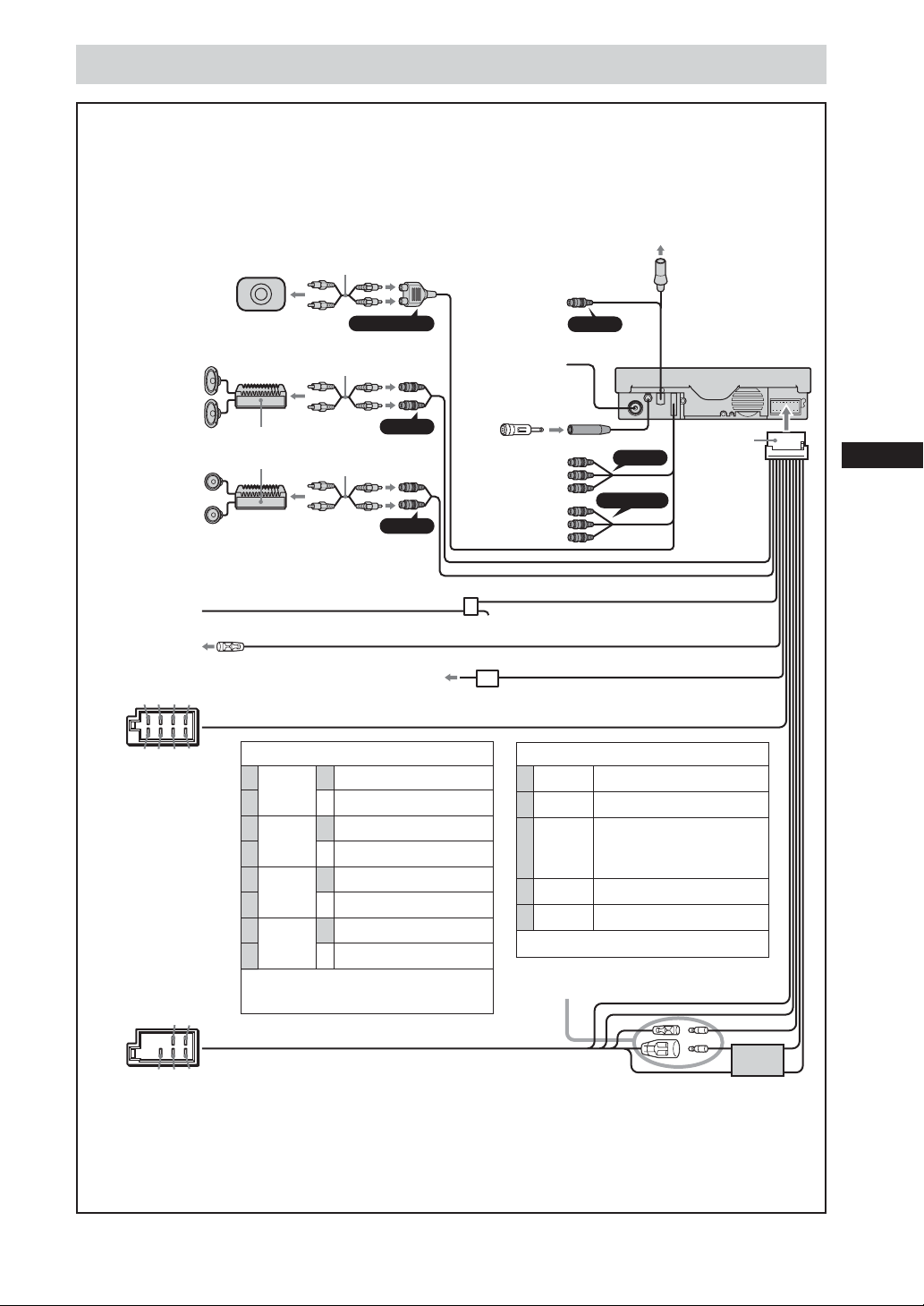
Connecting without optional TV tuner unit
* Note for the aerial connecting
If your car aerial is an ISO (International Organization for Standardization) type, use the supplied adaptor qd to
connect it. First connect the car aerial to the supplied adaptor qd, then connect it to the aerial jack of the main unit.
This terminal is not
used in this case.
AUX 3
AUX 2
REAR MONITOR OUT
Power
supply
leads 1
(for main
unit)
Active subwoofer
(optional)
Rear speakers
(optional)
Front speakers
(optional)
Amplifiers
(optional)
RCA interconnects
(optional)
SUB OUT (MONO)
RCA interconnects
(optional)
REAR L/R
RCA interconnects
(optional)
FRONT L/R
To the optional
back camera or
video
RC-104 (optional)
digital output
Aerial adaptor qd
From car aerial*
To game etc.
To rear
monitor etc.
Parking brake
switch lead of car
A AMP REM
13 5 7
To the +12 V power terminal
of the back lamp lead of car
Protection device
Light green (2.5 m)
Blue/whiteMax. supply current 0.3 A
Purple/White (5 m)
C from the car’s speaker connector
24 6 8
C from the car’s speaker connector
1 Purple
2
3 Grey
4
5 White
6
7 Green
8
+ Speaker, Rear, Right
– Speaker, Rear, Right
+ Speaker, Front, Right
– Speaker, Front, Right
+ Speaker, Front, Left
– Speaker, Front, Left
+ Speaker, Rear, Left
– Speaker, Rear, Left
Negative polarity positions 2, 4, 6,
and 8 have striped cords.
D from the car’s power connector
4 Yellow continuous power supply
5 Blue power aerial control
6 Orange/ switched
White illumination power
supply
7 Red switched power supply
8Black earth
Positions 1, 2, and 3 do not have pins.
See “Power connection diagram”
on next page for details.
57
D from the car’s power connector
4
68
A To AMP REMOTE IN of an optional power amplifier
This connection is only for amplifiers. Connecting any other system may damage the unit.
Warning
If you have a power aerial without a relay box, connecting this unit with the supplied power
supply leads 1 may damage the aerial.
Fuse
(10 A)
9
Power connection diagram
Auxiliary power connector may vary depending on the car. Check your car ’s auxiliary power connector
diagram to make sure the connections match correctly. There are three basic types (illustrated below). You
may need to switch the positions of the red and yellow leads in the car stereo’s power connecting cord.
After matching the connections and switched power supply leads correctly, connect the unit to the car’s
power supply. If you have any questions and problems connecting your unit that are not converted in
this manual, please consult the car dealer.
Auxiliary power connector
B
Red
Yellow
4 Yellow switched power supply
7 Red continuous power supply
Red
Yellow
A
C
Red
Yellow
4 Yellow continuous power supply
7 Red switched power supply
Red
Yellow
the car without ACC position
Red
Yellow
Red
Yellow
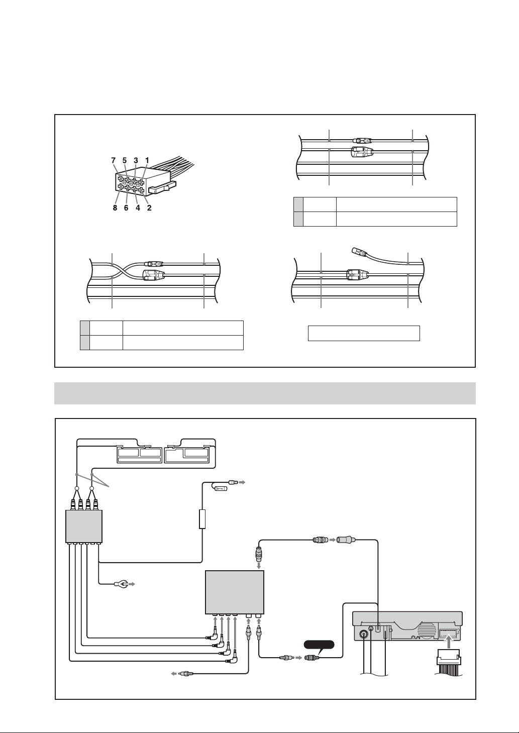
Connecting with optional TV tuner unit (For Russia and Ukraine only)
Film aerial
Aerial cord
Tuner
amplifier
unit
To a metal point
of the car
To the optional back camera
or video
10
To the +12 V power terminal which is
energized in the accessory position of the
ignition key switch. Be sure to connect the
black ground lead first.
* For Russia and
TV tuner unit *
XT-V70
(optional)
AUX 3
Ukraine only
 Loading...