

Page 1

Digital Alignment System INY Corporation P.E.
AS
Digital Alignment System TM
DAS
Adjustment Software for the
X2R/N2/N2H/24W1-Chassis Color Graphic Display
Version : J3.0
User's Manual
INY Corporation, P.E.
November 29, 1999
Page i
Page 2

Digital Alignment System INY Corporation P.E.
Prepared by :
Sony Ichinomiya Corporation
6, Ikejiri, Takada, Ichinomiya-shi
Aichi-Ken. 491-01 Japan
For :
Sony Electronic, Inc.
DAS and Digital Alignment System are Trademarks of Sony Electronics, Inc.
Copyright 1995 Sony Electronics, Inc.
Page ii
Page 3

Digital Alignment System INY Corporation P.E.
Table of Contents
1 What this manual is all about............................................................................................................ 1
1.1 What's New................................................................................................................................ 1
2 How to use this manual...................................................................................................................... 1
3 Computer Hardware Requirements.................................................................................................2
3.1 Connecting the Security Key to the PC......................................................................................5
3.2 Connecting the Mouse to the PC...............................................................................................5
3.3 Connecting the Sony Monitor.................................................................................................... 5
3.4 Connecting the Signal Generator to the Monitor.......................................................................6
3.5 Connecting the Signal Generator to the PC ............................................................................... 6
3.5.1 Astro Design VG-819, VG-819S and VG-823............................................................... 6
3.5.2 Team Systems VG-515................................................................................................... 7
3.5.3 Quantum Data 801GF..................................................................................................... 7
3.5.4 Quantum Data 801GF-ISA............................................................................................. 7
3.6 Altering the Default Serial Port Assignments............................................................................. 7
3.6.1 Altering The Default Comm Port.................................................................................... 8
3.6.2 Altering The Default Interrupt Number......................................................................... 10
4 Error and Warning Screens............................................................................................................. 11
4.1 Error Type 1 ............................................................................................................................ 11
4.2 Error Type 2 ............................................................................................................................ 14
4.3 Error Type 3 ............................................................................................................................ 15
4.4 Error Type 4 ............................................................................................................................ 16
4.5 Error Type 5 ............................................................................................................................ 17
4.6 Warning Type 1 ....................................................................................................................... 17
4.7 Warning Type 2 ....................................................................................................................... 18
5 Quick Starts....................................................................................................................................... 19
6 Installing the software ...................................................................................................................... 20
6.1 Installation Procedure............................................................................................................... 20
6.2 Installation Errors..................................................................................................................... 24
6.2.1 Canceled by User........................................................................................................... 24
6.2.2 Insufficient Disk Space.................................................................................................. 25
6.2.3 Insufficient RAM........................................................................................................... 27
6.2.4 Unrecoverable Errors.................................................................................................... 28
Page iii
Page 4

Digital Alignment System INY Corporation P.E.
7 Starting the Program........................................................................................................................ 29
8 Stopping the Program...................................................................................................................... 31
9 How to use the Keyboard................................................................................................................. 32
9.1 Normal Keys............................................................................................................................ 32
9.2 Hot Keys.................................................................................................................................. 34
10 How to use the Mouse .................................................................................................................... 34
11 How to Use the File Selection Dialog Box..................................................................................... 36
11.1 Using the Mouse for Selection............................................................................................... 37
11.2 Using the Keyboard for Selection .......................................................................................... 37
12 Monitor and Program Status......................................................................................................... 38
12.1 Monitor Status Line............................................................................................................... 38
12.2 Program Status....................................................................................................................... 39
13 Setup Menu..................................................................................................................................... 40
13.1 Choosing a Monitor Model.................................................................................................... 40
13.2 Choosing a Signal Generator Model...................................................................................... 42
13.3 Displaying Version Information ............................................................................................. 44
14 Adjustments Menu......................................................................................................................... 45
14.1 Alignment of Factory Presets................................................................................................. 48
14.2 Control Signal Generator....................................................................................................... 54
14.2.1 Special Considerations ................................................................................................ 58
14.2.1.1 Astro Design VG-819(S) ................................................................................. 58
14.2.1.2 Team Systems VG-515pc ................................................................................ 58
14.2.2 User Pattern ................................................................................................................ 58
14.2.2.1 Astro Design VG-819(S) ................................................................................. 59
14.2.2.2 Team Systems VG-515pc ................................................................................ 59
14.2.3 MEME Pattern............................................................................................................60
14.2.3.1 Astro Design VG-819(S) ................................................................................. 60
14.2.3.2 Team Systems VG-515pc ................................................................................ 60
14.3 Maintenance........................................................................................................................... 61
14.4 Step-by-Step Procedures........................................................................................................ 62
14.5 Failure Information................................................................................................................. 64
15 File Menu......................................................................................................................................... 68
Page iv
Page 5

Digital Alignment System INY Corporation P.E.
15.1 Write EEPROM File to MONITOR...................................................................................... 69
15.2 Save EEPROM Data to File .................................................................................................. 70
15.3 MPU Board............................................................................................................................ 71
16 EDID Menu..................................................................................................................................... 73
16.1 EDID Editor .......................................................................................................................... 74
17 Hints and Kinks.............................................................................................................................. 77
17.1 Hints....................................................................................................................................... 77
17.2 Kinks...................................................................................................................................... 77
Page v
Page 6

Digital Alignment System INY Corporation P.E.
Screen Depictions
Screen 1: Missing Security Key Warning................................................................................................. 5
Screen 2: Monitor Retry Popup............................................................................................................. 12
Screen 3: Signal Generator Retry Popup ............................................................................................... 13
Screen 4: Mode Selection Error............................................................................................................. 14
Screen 5: Frequency Determination Error.............................................................................................. 15
Screen 6: Disk Not Ready Error............................................................................................................ 16
Screen 7: Critical Disk Error.................................................................................................................. 17
Screen 8: Signal Generator Warning Message....................................................................................... 18
Screen 9: First Install Screen.................................................................................................................. 20
Screen 10: Second Installation Screen ................................................................................................... 21
Screen 11: Installation Confirmation Screen.......................................................................................... 22
Screen 12: Installation in Progress......................................................................................................... 22
Screen 13: Installation Complete Screen................................................................................................23
Screen 14: Installation Canceled by User............................................................................................... 24
Screen 15: Insufficient Disk Space?....................................................................................................... 25
Screen 16: Target Disk Full ................................................................................................................... 26
Screen 17: Insufficient RAM?................................................................................................................ 27
Screen 18: Unrecoverable Error............................................................................................................. 28
Screen 19: Introduction and Copyright Screen...................................................................................... 29
Screen 20: DAS Main Screen................................................................................................................ 30
Screen 21: Exit Menu ............................................................................................................................ 31
Screen 22: File Selection Dialog Box..................................................................................................... 36
Screen 23: Monitor Status Line............................................................................................................. 38
Screen 24: Program Status..................................................................................................................... 39
Screen 25: Setup Pulldown Menu..........................................................................................................40
Screen 26: Select Monitor Screen..........................................................................................................41
Screen 27: Detect Monitor Model......................................................................................................... 41
Screen 28: Can’t Detect the Monitor ..................................................................................................... 42
Screen 29: Select Signal Generator Screen............................................................................................ 43
Screen 30: Manual Generator Setup...................................................................................................... 43
Screen 31: Install Disk Version.............................................................................................................. 44
Screen 32: Adjustments Pulldown Menu............................................................................................... 45
Screen 33: Connecting the Monitor................................................................................................... 46
Screen 34: Connecting to the Signal Generator..................................................................................... 47
Screen 35: Factory Presets Screen......................................................................................................... 48
Screen 36: Mode Alignment Flag........................................................................................................... 49
Screen 37: In case of 24W1 Factory Preset ........................................................................................... 49
Screen 38: Pattern Selection on Factory Presets Screen........................................................................ 51
Screen 39: Factory Presets Restore........................................................................................................ 52
Screen 40: Factory Presets Safety Valve................................................................................................ 53
Page vi
Page 7

Digital Alignment System INY Corporation P.E.
Screen 41: Choose a Generator First ..................................................................................................... 54
Screen 42: Control Signal Generator Screen.......................................................................................... 55
Screen 43: Controlling the Generator .................................................................................................... 56
Screen 44: Select a Mode First .............................................................................................................. 57
Screen 45: Unused Mode Selected ........................................................................................................ 58
Screen 46: VG-819(S) Panel ROM Required........................................................................................ 60
Screen 47: Maintenance......................................................................................................................... 61
Screen 48: Step-by-Step Menu.............................................................................................................. 62
Screen 49: Completed Step-by-Step Procedure Marked with an "*"..................................................... 63
Screen 50: Failure Information(N2H).................................................................................................... 64
Screen 51: Failure Information(N2)....................................................................................................... 64
Screen 52: Failure Information(X2R) .................................................................................................... 65
Screen 53: Failure Information (24W1)................................................................................................. 65
Screen 54: File Menu............................................................................................................................. 68
Screen 55: Write EEPROM File to MONITOR.................................................................................... 69
Screen 56: Save EEPROM Data to File................................................................................................. 70
Screen 57: First MPU Board Screen......................................................................................................71
Screen 58: Confirmation for a DDC signal adapter................................................................................ 72
Screen 59: MPU Board Complete......................................................................................................... 72
Screen 60: EDID Menu......................................................................................................................... 73
Screen 61: Confirmation for a DDC signal adapter................................................................................ 74
Screen 62: Input # Dialog...................................................................................................................... 75
Screen 63: EDID Editor......................................................................................................................... 75
Screen 64: Confirmation for saving the EDID data................................................................................ 76
Page vii
Page 8

Digital Alignment System INY Corporation P.E.
1 What this manual is all about
This manual is the user's manual for the Sony DAS(Digital Alignment System) software. The DAS
program was designed as an aid in adjusting the X2R/N2/N2H/24W1-Chassis monitor.
1.1 What's New
• Support for the 24W1 chassis has been added.
2 How to use this manual
The manual is designed to guide you step by step in the installation and use of the DAS software. It is
not meant to teach the theory and techniques of monitor adjustment.
Section 5 will let the impatient get up and running quickly. Sections 6 and on give a detailed description
of the operation of the software.
Section 4 shows you the kinds of error screens you may see and what you can do to correct the error.
READ THIS SECTION EVEN IF YOU ARE AN EXPERT!
Page 1
Page 9

Digital Alignment System INY Corporation P.E.
3 Computer Hardware Requirements
The DAS program must be installed onto a hard disk before it will run.
The DAS system requires :
• An IBM AT or compatible with
· 80486 66MHz or higher CPU
· I/O channel running at 8 MHz
· 640K of memory
· DOS Version 3.3 or higher or DOS/V Version 6.2 or higher
· Monochrome Monitor
· One of this diskette drives / 1.44M 3.5"
· Optionally:
A hard disk with at least 2Mb free
EGA or VGA Monitor
• SentinelPro Security Key
• Monitor to Signal Generator cable
Depending on the signal generator you are using, you will need the necessary cabling to connect
the generator to the video input of the monitor.
For a monitor which have a standard VGA style connector or a DB style 15 pin DIN connector,
you will require an adapter to convert BNC cables from the signal generator to the DB connector
on the end of the cable from the monitor.
The Adapter for standard VGA style connector:
Monitor End
VGA Connector
Pin 1 Red
Pin 6 Red Return
Pin 2 Green
Pin 7 Green Return
Pin 3 Blue
Pin 8 Blue Return
Pin 13 Horizontal Sync
Pin 14 Vertical Sync
Pin 10 Sync Return
Pin 5 Ground
Signal Generator End
RGB BNC
Page 2
Page 10
Digital Alignment System INY Corporation P.E.
The Adapter for DB style 15 pin DIN connector:
Monitor End
DB-15
Pin 2 Red
Pin 1 Red Return
Pin 5 Green
Pin 6 Green Return
Pin 9 Blue
Pin 13 Blue Return
Pin 15 Horizontal Sync
Pin 12 Vertical Sync
Pin 4 Sync Return
Signal Generator End
RGB BNC
• Monitor to PC Interface cable
This cable is supplied by Sony. It has a DB-9 connector on one end to connect to the RS232
board and an 8-pin DIN connector on the other end to connect to the monitor.
• DIN Adapter Box
For the X2R/N2/N2H chassis, an adapter box that converts the internal monitor connector to an
8-pin DIN connector. The cable from this adapter box plugs into connector on a PCB inside of
the X2R/N2/N2H. The X2R/N2/N2H enclosure must be removed to make this connection.
Optionally,
• A Microsoft Compatible Mouse connected on COM1, as a Bus Mouse or as a PS/2 Mouse
· A serial mouse connected to a standard PC COM1 serial port
· You may need a DB-25 to DB-9 adapter if your PC has a different type connect than your
mouse
· A PS/2 mouse should be connected to the PS/2 mouse connector
· A bus mouse connected to a bus mouse card.
· You must install the appropriate mouse driver software, see Section 3.2
• A RS-232 Interface Board jumped as COM3 and COM4.
• A Sony supplied Sealevel 3083-S101 RS-232/RS-422 Interface Board jumped as COM2
and COM3. The bottom connector is the RS-232 port -COM2.
Page 3
Page 11

Digital Alignment System INY Corporation P.E.
• A supported Signal Generator on RS-232 COM3
· Supported Model(s) :
Astro Design VG-819, Astro Design VG-819S, Astro Design VG-823 or
Quantum Data 801GF
· A “VG-819(S), VG-823 or QD801GF Host Mode Cable” to connect the generator
to the PC. This cable is supplied by Astro Design/Quantum Data or can be assembled
by you. This cable has DB-25 or DB-9 connectors on each end. See Section 3.5.1.
Team Systems VG-515pc
· This signal generator is a card that plugs inside of your PC. There are no cabling
requirements between the PC and the generator. The VG-515 appears to the PC as a
serial port on COM4.
· Follow the instructions that come with the generator when installing it into your PC.
· Standard PC COM2 or COM3 serial port if you are using a VG-819(S), VG-823 or QD801GF
signal generator (the signal generator defaults to COM3 but can be moved, see Section 0)
· You may need a DB-9 to DB-25 adapter if your PC has a DB-9 connector for the port.
Page 4
Page 12
Digital Alignment System INY Corporation P.E.
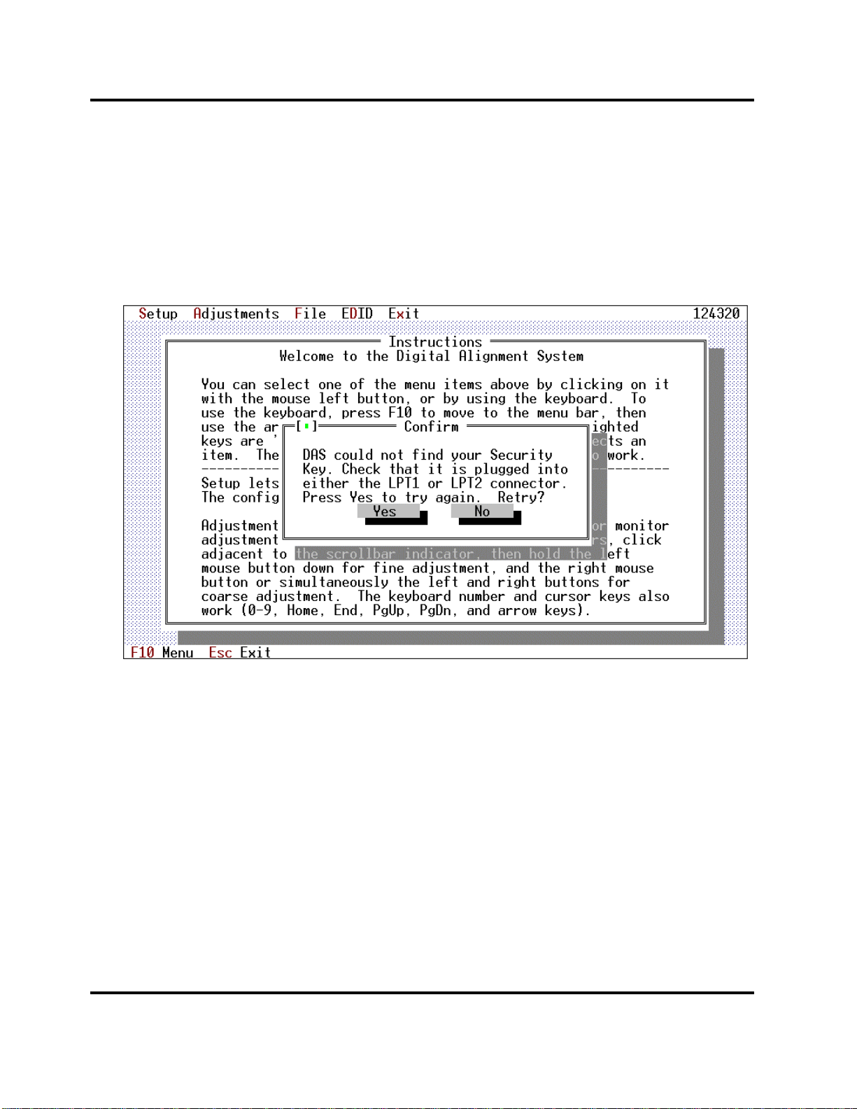
3.1 Connecting the Security Key to the PC
The SentinelPro security key supplied with the DAS program must be plugged into either the LPT1 or
LPT2 printer ports. If you have a printer cable already connected to the port, unplug the printer, plug the
security key into the computer port and then plug the printer into the other connector on the key.
The DAS software periodically checks for the presence of the key. If the key is not found a popup
message is displayed on the screen. The message is shown on Screen 1.
Screen 1: Missing Security Key Warning
You may press the [NO] button to terminate the DAS program immediately or you may install the key
and then press the [YES] button to continue.
3.2 Connecting the Mouse to the PC
Computer mice, like all real mice, are different. How you install your mouse depends on the
manufacturer of the mouse. Follow their instructions as you install the mouse on COM1. If you are given
an option during the installation of the mouse, configure the mouse as a Two-Button Microsoft
Compatible mouse.
3.3 Connecting the Sony Monitor
The monitor is connected to the PC COM2 using the special cable supplied by Sony.
Page 5
Page 13

Digital Alignment System INY Corporation P.E.
3.4 Connecting the Signal Generator to the Monitor
The signal generator should be connected to the monitor by using 5 coaxial cables. Connect:
Red Video Green Video
Blue Video Horizontal/Composite Sync
Vertical Sync
3.5 Connecting the Signal Generator to the PC
The method of connecting the signal generator to the PC depends on which supported signal generator
you have selected.
The DAS program supports these signal generators:
• Astro Design VG-819(S), VG-823 or Quantum Data 801GF connected to the PC RS-232
COM2 or RS-232 COM3 port (defaults to COM3 but can be moved, see Section 0)
• Team Systems VG-515 plugged into the PC's I/O channel bus.
• Quantum Data 801GF-ISA plugged into the PC's ISA bus.
3.5.1 Astro Design VG-819, VG-819S and VG-823
The DAS program automatically supports the Astro Design VG-819, VG-819S and VG-823 Digital
Video Generator. You can cable them to the PC and the DAS program will automatically control it to
select the correct frequencies for each adjustment.
The VG-819(S) or VG-823 should be connected to the PC's RS-232 COM2 or RS-232 COM3 (the
default is COM3 but can be changed, see Section 0) port by using a special serial cable supplied by Astro
Design or assembled by you. The cable is called a Host Mode Cable".
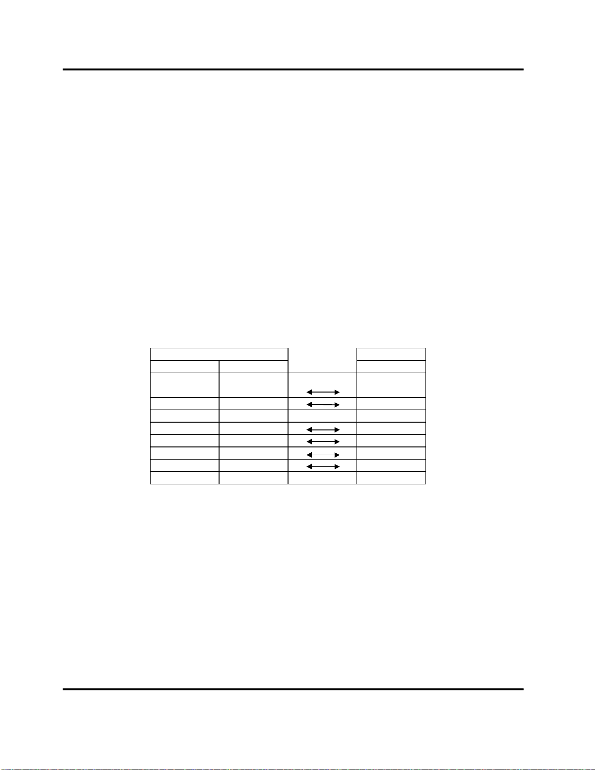
The cable is wired as follows:
PC RS232C VG-819(S) VG-823
DB-9(Female) DB-25(Female) DB-25(Male) DB-9(Male)
1 8 8 1
2 3 3 2
3 2 2 3
4 20 20 4
5 7 7 5
6 6 6 6
7 4 4 7
8 5 5 8
9 22 22 9
Page 6
Page 14
Digital Alignment System INY Corporation P.E.
The VG-819S has a feature not found on the VG-819. The 819S model can turn off its Composite Sync,
Horizontal Sync and Vertical Sync outputs. If you use the 819, you may have to disconnect the
Horizontal and Vertical Sync cable when adjusting "Sync on Green" modes.
3.5.2 Team Systems VG-515
The DAS program automatically supports the Team Systems VG-515pc Programmable Video
Generator. This board plugs right into the I/O channel inside of your PC. On the back of the board is a
standard VGA connector that connects to the monitor.
3.5.3 Quantum Data 801GF
The DAS program automatically supports the Quantum Data 801GF Programmable Video Generator.
This signal generator should be connected to the PC's RS-232 COM2 or RS-232 COM3 (the default is
COM3 but can be changed, see Section 0) port by using a special serial cable supplied by Quantum Data
or assembled by you.
The cable is wired as follows:
PC RS232C QD801GF
DB-9(Female) DB-25(Female) DB-9(Male)
1 8 1
2 3 3
3 2 2
4 20 6
5 7 5
6 6 4
7 4 8
8 5 7
9 22 9
3.5.4 Quantum Data 801GF-ISA
The DAS program automatically supports the Quantum Data 801GF-ISA Programmable Video
Generator. This board plugs right into the ISA bus inside of your PC. On the back of the board is a
standard VGA connector that connects to the monitor.
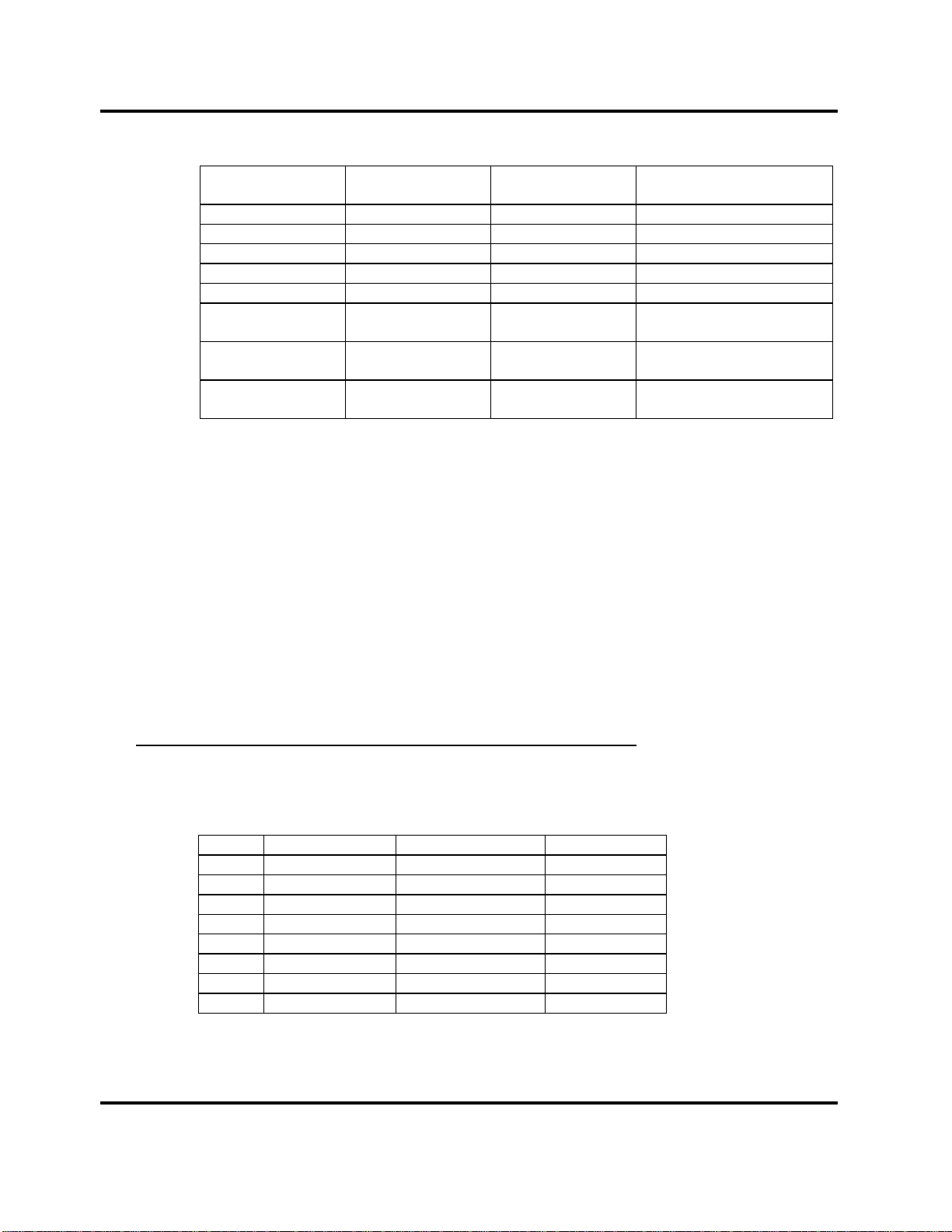
3.6 Altering the Default Serial Port Assignments
By now you should see that the different combinations of monitors and generators could cause havoc
with the RS-232 serial ports at the back of your PC. Here is a summary of the default requirements :
Page 7
Page 15
Digital Alignment System INY Corporation P.E.
Device Default Comm
Port
Serial Mouse COM1 4 RS-232
Bus Mouse COM4 varies Bus Mouse Board
Monitor COM2 not used RS-232
VG-819(s) COM3 not used RS-232
VG-823 COM3 not used RS-232
VG-5151pc COM4 not used built onto VG-515pc
Quantum Data
801GF
Quantum Data
801GF-ISA
COM3 4 RS232
not used not used built onto 801GF-ISA
Default
Interrupt Number
PC Board
Type
board itself
board itself
3.6.1 Altering The Default Comm Port
Depending on your exact needs, you can change these default ports by using DOS 'Environment Strings'.
These strings can be entered by you on the DOS command line or put into your autoexec.bat file. The
format of the command to create one of these strings is:
set string = #
In place of the word 'string' use one of these names depending on the device that you want to reassign:
SIGGENPORT VG-819(S), VG-823, QD801GF, QD801GF-ISA
N1PORT For all X2R/N2/N2H/24W1 Monitors
For the monitors, the VG-819(S), the VG-823, and the QD801GF:
In place of the '#' sign in the 'set' command, enter a number from 1 to 8 which identifies which serial port
that device is connected to:
# Port Port Address(Hex) Monitor
1 COM1 3F8 All
2 COM2 2F8 All
3 COM3 3E8 All
4 COM4 2E8 All
5 COM5 320 N1PORT only
6 COM6 328 N1PORT only
7 COM7 338 N1PORT only
8 COM8 280 N1PORT only
Page 8
Page 16
Digital Alignment System INY Corporation P.E.
ISA7
ISA5
ISA3
ISA1
ISA0
268
258
318
308
300
(Hex)
= jumper in
= jumper out
COM1 and COM2 are the standard two serial ports found in most PC's. COM3 and COM4 can usually
be added to the PC with the addition of an I/O Expansion Board. The remaining ports are for special
boards that use non-standard port addresses implemented on combination RS232 boards.
For the QD801GF-ISA:
In place of the '#' sign in the 'set' command, enter a number from 1 to 8 which identifies which jumper
setting is made on the QD801GF-ISA card:
# ISA Port Address(Hex)
1 0 300
2 1 308
3 2 310
4 3 318
5 4 250
6 5 258
7 6 260
8 7 268
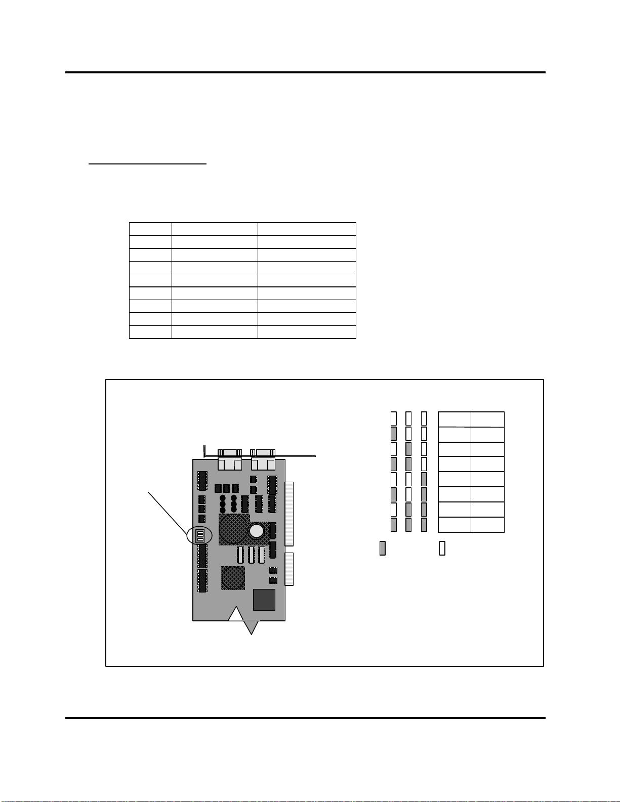
Here is an excerpt from the Quantum Data Model 801GF-ISA Quick Start Guide :
Prepare the card for your correct ISA or base I/O address.
This is done by placing the provided jumpers in the pattern for your ISA or
I/O shown in this table. The card comes with a default setting of ISA 0
Jumper
Locations
There are two other jumper positions:
X and M. Position X is empty and M
always has a jumper.
GF
(base I/O 300H).
Base I/O
Figure 1: QD801GF-ISA Jumper Setting
Page 9
Page 17
Digital Alignment System INY Corporation P.E.
After you have entered one of these 'set' command, you can check what the PC thinks you typed by
entering the 'set' command without anything following it:
set
Here is what 'set' commands would look like for the default port assignments (you don't have to use
these commands if the defaults are correct for your case):
set N1PORT=2
set SIGGENPORT=3
Now, for example, say you have a machine without a mouse. You can connect the VG-819 to COM1
and the monitor to COM2 by issuing these commands before you run the DAS program:
set N1PORT=2
set SIGGENPORT=1
The first one isn't actually needed anyway since it is the default port.
3.6.2 Altering The Default Interrupt Number
Usually the only way to use a different interrupt number is to change the default COM port assignment.
In most cases, the interrupt number is fixed to the COM port as follows:
Comm Port Interrupt Number
COM1 4
COM2 3
COM3 4
COM4 3
COM5-8 varies
Bus Mouse varies
Generally on a PC, the available interrupts for ports and mice are 2, 3, 4, 5, 7, 10, 11, and 12. On some
PC’s sound cards or other devices may already use some of these. Check your device documentation for
the best combination.
If you can, you should have the bus mouse use interrupt 10, 11 or 12. Then interrupts 3 and 4 are both
available for DAS devices.
Page 10
Page 18

Digital Alignment System INY Corporation P.E.
4 Error and Warning Screens
We think the Error and Warning Screens that you may see are very important. So important, in fact, that
we put this section of the User's Manual near the front.
The DAS program is designed to operate in as user friendly a manner as possible. The screens we display
may help you to get the program running correctly without having to get technical help.
There are five types of errors:
1. Communications errors
2. Monitor mode and frequency selection errors
3. Model information and errors
4. Disk Not Ready
5. Critical Disk Error
There are two types of warnings:
1. Horizontal frequency determination inaccurate
2. Signal Generator not set correctly
4.1 Error Type 1
When communicating with the monitor and signal generator, the program will try several times before
indicating a failure. If the program cannot establish communication, it will put up a screen (Screen 2 and
Screen 3) asking you if you want the program to try again.
Page 11
Page 19
Digital Alignment System INY Corporation P.E.
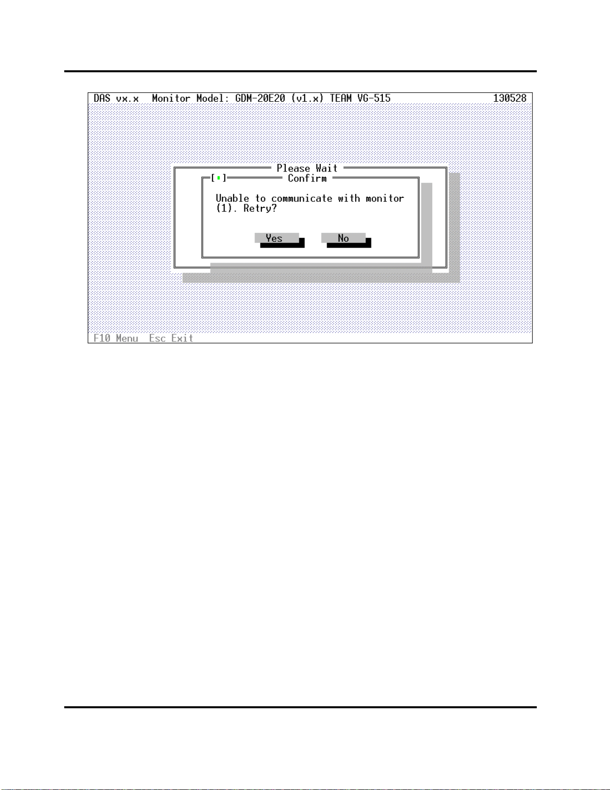
Screen 2: Monitor Retry Popup
This screen (Screen 2) shows a monitor communications problem. At this point, you should check that
the RS-232 board and monitor cables are correctly installed (correct port, etc.). Press [YES] to have the
program try again. Press [NO] to return to the main screen. You should always press [YES] once or
twice before you give up. If the DAS cannot establish communications with the monitor, you may have a
defective monitor, RS-232 board or cable.
Page 12
Page 20
Digital Alignment System INY Corporation P.E.
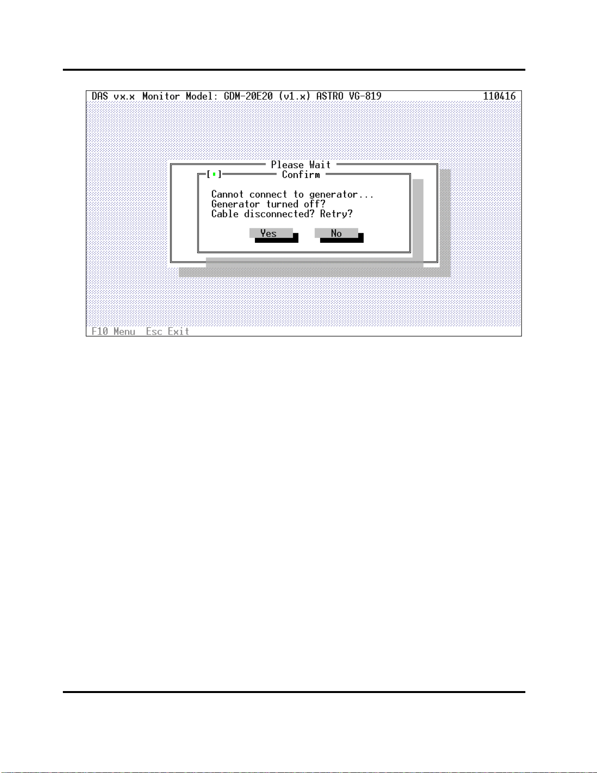
Screen 3: Signal Generator Retry Popup
This screen (Screen 3) shows a signal generator communications problem. At this point, you should
check that your serial board and signal generator cable are correctly installed. If you are using an Astro
Design VG-819(S), make sure you have wired the cable as shown in Section 3.5.1. Press [YES] to
have the program try again. Press [NO] to return to the main screen. You should always press [YES]
once or twice before you give up. If the DAS cannot establish communications with the signal generator,
you may have a defective signal generator, RS-232 serial board or cable.
Page 13
Page 21
Digital Alignment System INY Corporation P.E.
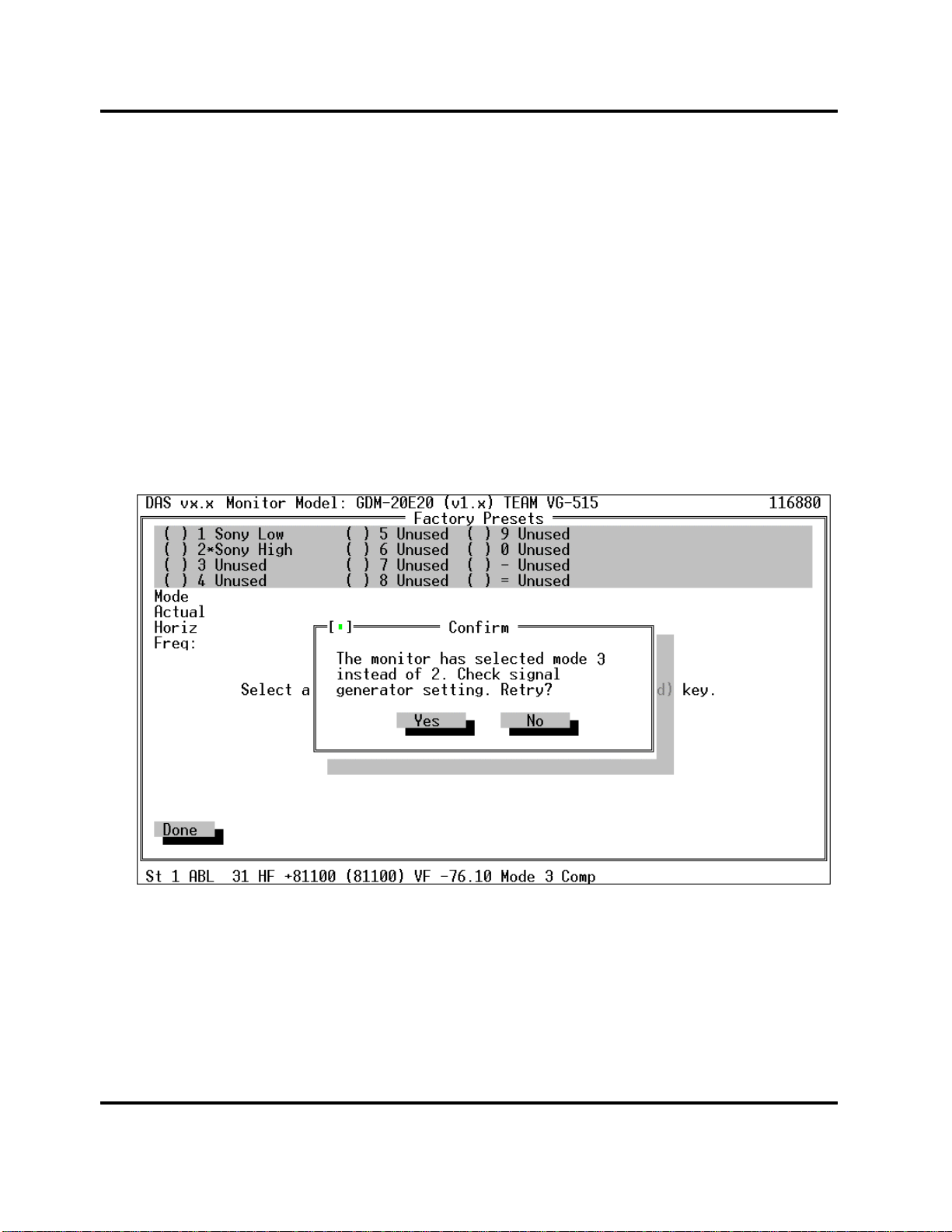
4.2 Error Type 2
There are cases where the internal horizontal frequency determination logic may not select the correct
mode within the monitor. This may have an external cause, such as an incorrectly setup signal
generator or an internal cause, such as the accuracy of the Timer/Counter inside of the monitor. If this
occurs, a screen (Screen 4) will display what was expected and what was actually determined. Check the
generator to be sure that it is setup correct. Check the cables to be sure they are wired correctly and
plugged in to the correct connectors. Correct it if necessary and then select [YES] to retry the operation.
If you are not using a manual generator, the problem is within the monitor. In this case contact technical
support.
If you are using a VG-819 generator, there is an additional possible cause for this error. The VG-819
cannot turn off its Sync outputs and will have cases where sync information is contained on the green
output BNC as well as the CS, HS and/or VS output BNC's. If you use the 819, you may have to
disconnect the Horizontal and Vertical Sync cables if adjusting "Sync on Green" modes.
Screen 4: Mode Selection Error
Page 14
Page 22

Digital Alignment System INY Corporation P.E.
There are also cases where the accuracy of the basic frequency determination logic in the monitor
prevents the monitor from determining the exact input horizontal frequency. This is not a problem as
long as the monitor determines the correct mode. An informational screen (Screen 5) will be displayed to
tell you what happened. Press [OK] to continue the adjustment.
The DAS program is looking for 1) correct mode selected and 2) correct horizontal frequency. If the
mode is correctly selected, proceed with adjustment.
Screen 5: Frequency Determination Error
4.3 Error Type 3
If the DAS model information contained in its internal data base becomes corrupted, you will get an
error indicating a "Data Base" error. If this occurs you should reinstall the software following the
procedure in Section 6.
If the problem persists, copy down the error message and contact technical support.
Page 15
Page 23
Digital Alignment System INY Corporation P.E.
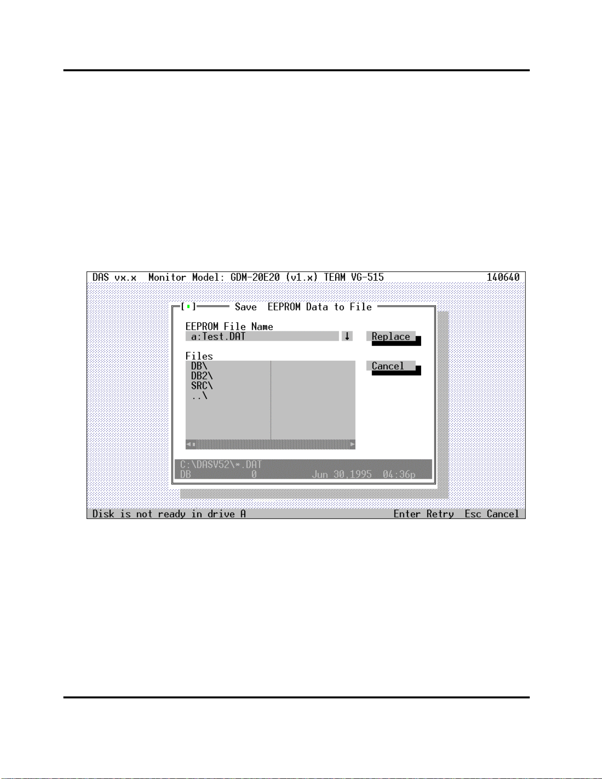
4.4 Error Type 4
When you are using a diskette for reading or writing EEPROM files, if there is no diskette in the drive,
you will see this screen (Screen 6).
Press the Enter key to retry the operation after inserting the diskette in the drive. Press the Esc key to
cancel the operation. You may want to cancel the operation if, for example, you tried to access disk drive
A: when, in fact, you wanted to access disk drive B:.
If this error repeats when you believe it should not, you may have a hardware problem.
Screen 6: Disk Not Ready Error
Page 16
Page 24
Digital Alignment System INY Corporation P.E.
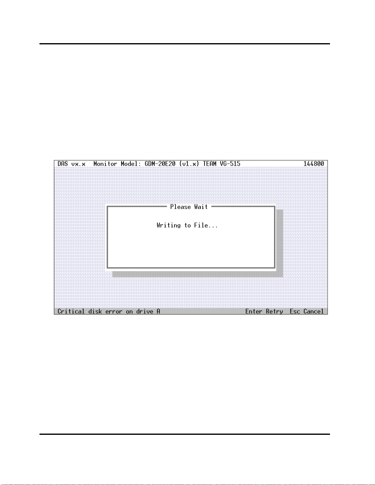
4.5 Error Type 5
When you are using a diskette for writing EEPROM files, if the diskette in the drive is write protected,
you will see this screen (Screen 7).
Press the Enter key to retry the operation after removing the write protect tab from the diskette. Press
the Esc key to cancel the operation. You may want to cancel the operation if, for example, you had the
wrong diskette in the drive.
If this error repeats when you believe it should not, you may have a hardware problem.
Screen 7: Critical Disk Error
4.6 Warning Type 1
Each time the monitor switches modes, the DAS program reads the horizontal frequency register and
checks its value. The program does this to be sure that the signal generator has been setup correctly. The
accuracy of the frequency measurement in the monitor may cause a warning message to popup on the
screen (Screen 5) at this point. The accuracy, according to the monitor specification, is plus/minus 5
microseconds of 255 horizontal periods. The monitor itself has a resolution of plus/minus 100 Hertz. The
DAS program will warn you that the monitor has determined a different frequency than what was
expected. It is a warning only. Press the [OK] button to have the program continue.
This check is performed in the Factory Presets screen of the DAS program.
Page 17
Page 25
Digital Alignment System INY Corporation P.E.
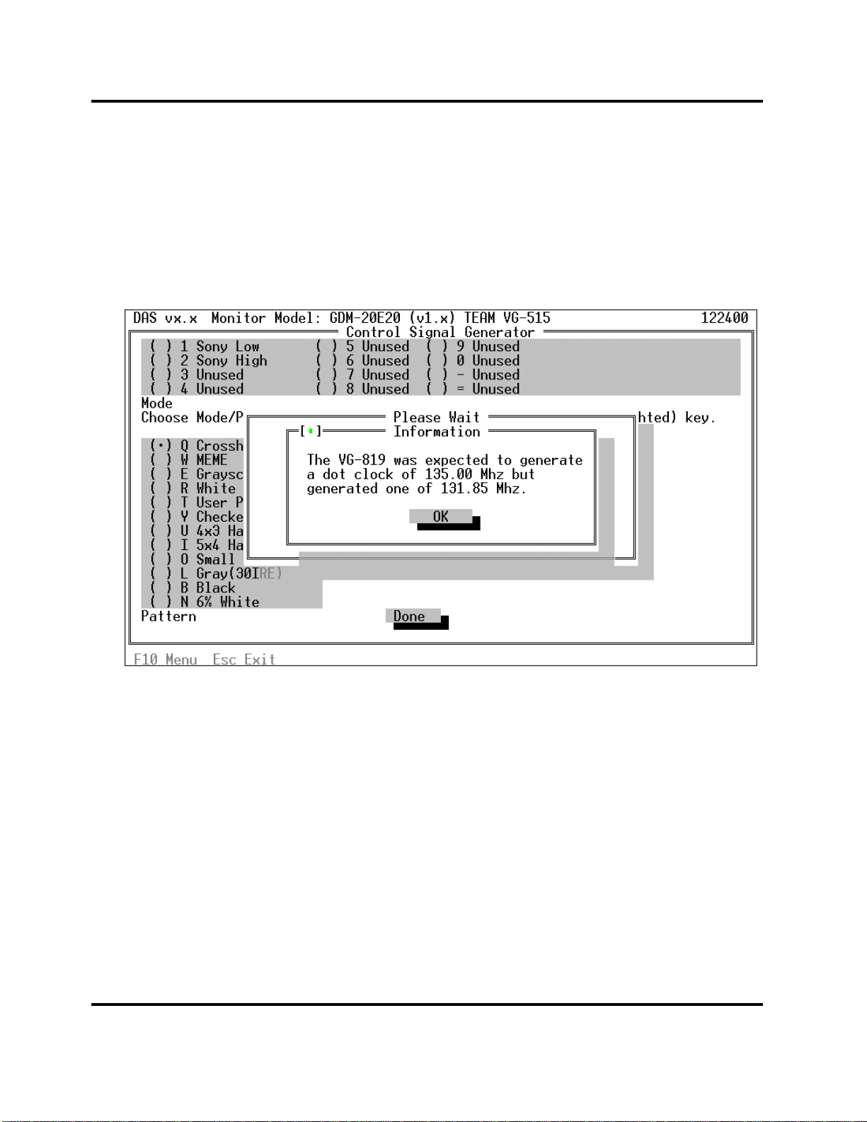
4.7 Warning Type 2
If you are connected to a supported signal generator, the DAS program will automatically control the
setting of the generator. Part of this process is to make sure that the signal generator is operating
correctly. To do this, the DAS program will double check the generator after programming it for the
selected mode. If the generator does not confirm that it is correctly set, you will see a warning screen
(Screen 8). It is a warning only. Press the [OK] button to the have program continue.
Screen 8: Signal Generator Warning Message
Page 18
Page 26

Digital Alignment System INY Corporation P.E.
5 Quick Starts
These quick start instructions are for users who are familiar with menu based user interfaces. If they don't
make any sense to you or you can't figure out what is going on, skip this and continue with Section 6.
• Connect the RS-232 interface cable between the COM2 port on your PC and the round
connector on the rear of the monitor.
• Insert the Distribution Diskette into drive A.
• At the DOS prompt, type a: and press the Enter key.
• At the DOS prompt, type install and follow the installation instructions. You can install the
DAS program onto a hard disk. It will not run from the Distribution Diskette and you cannot
install it onto another diskette.
• At the DOS prompt, type das and press the Enter key.
• Press F10 to activate the menu bar and use the arrow keys and the Enter key, select the Setup
menu.
• From the Setup menu, select a monitor.
• From the Setup menu, select a signal generator.
• Activate the menu bar and from the Adjustments menu, select Step-by-Steps.
• Activate the menu bar and from the Exit menu, select Exit to return to the DOS prompt.
Now, please, read the rest of this manual.
Page 19
Page 27

Digital Alignment System INY Corporation P.E.
6 Installing the software
This section tells you how to install the DAS software on a hard disk. You must install DAS onto your
hard disk. DAS will not run directly from the distribution diskette. It cannot be installed on another
diskette.
6.1 Installation Procedure
Insert the distribution diskette into either your A or B drive. At the DOS prompt, type either a:\install or
b:\install depending on which diskette drive you are using.
When the install program starts to run, it will show an introductory screen (Screen 9). Press the Enter
key continue the installation.
CAUTION :
Screen 9: First Install Screen
To guarantee that DAS vJx.x will run stable on your PC system, free conventional DOS
memory of 580K is required !
(You can achieve this by using the DOS ‘memmaker’ command)
Page 20
Page 28

Digital Alignment System INY Corporation P.E.
Then a screen (Screen 10) will appear which will show in which directory on which disk drive the
program will be installed in. Both the drive letter and the directory can be changed.
Screen 10: Second Installation Screen
The drive will default to the first hard disk on your machine, usually C:. If this is acceptable, just press
the Enter key to confirm the drive. To change the disk drive letter, just type in the new drive letter when
the field is highlighted and press the Enter key.
The directory will default toDAS. You should not change this unless you already have a DAS
directory used by some other application. If this is acceptable, just press the Enter key to confirm the
directory. To change the directory, just type in the new directory name when the field is highlighted and
press the Enter key.
Page 21
Page 29

Digital Alignment System INY Corporation P.E.
When the final confirmation screen (Screen 11) appears, press the Enter key one more time as final
confirmation. You can press the Esc key at any time to terminate the installation.
Screen 11: Installation Confirmation Screen
Now the installation will begin (Screen 12). You will see each file name as it is transferred to the disk.
Screen 12: Installation in Progress
Page 22
Page 30

Digital Alignment System INY Corporation P.E.
When the installation is complete, the final screen (Screen 13) will be displayed. Press the Enter key to
return to DOS.
Screen 13: Installation Complete Screen
Page 23
Page 31

Digital Alignment System INY Corporation P.E.
6.2 Installation Errors
There are four predomination error messages that you might see during installation.
6.2.1 Canceled by User
When you press Esc to cancel the installation (Screen 14). Press Esc again to confirm that you really
want to cancel the installation. If you press any other key, the installation will continue.
Screen 14: Installation Canceled by User
Page 24
Page 32

Digital Alignment System INY Corporation P.E.
6.2.2 Insufficient Disk Space
If there is not enough disk space on your disk to hold the files, you will see an error message (Screen
15). The DAS system requires 1 megabyte of free space to install.
If you are installing DAS on a disk that already has DAS installed, you will still get this error message.
But since the reinstalled DAS will write over the old version, no real additional disk space is needed.
Select CONTINUE in this case.
If this is a new installation and you see this message, you really don't have enough space. Select ABORT
in this case. You should retry the installation after freeing up at least 1Mb of disk space.
Screen 15: Insufficient Disk Space?
Page 25
Page 33

Digital Alignment System INY Corporation P.E.
If you selected to continue installation and during the install you run out of disk space, a message (Screen
16) will be displayed. Once this occurs, installation cannot be continued. Pressing any key cancels the
install. You will have to free up more disk space and then try the installation again.
Screen 16: Target Disk Full
Page 26
Page 34

Digital Alignment System INY Corporation P.E.
6.2.3 Insufficient RAM
DAS requires 640K of RAM in order to run. This screen (Screen 17) warns you that you don't have
enough installed RAM. This will not affect the installation so you may wish continued with the install.
However, you may not be able to run the DAS program once the installation is complete.
Screen 17: Insufficient RAM?
If you see this screen, you should probably select [ABORT] to terminate the installation. Install enough
additional memory to reach the 640K required and then repeat the installation procedure.
Page 27
Page 35

Digital Alignment System INY Corporation P.E.
6.2.4 Unrecoverable Errors
Other problems fall into the category of unrecoverable errors (Screen 18). In this case, usually the
diskette has been corrupted in one way or another. Contact technical support.
Screen 18: Unrecoverable Error
Page 28
Page 36

Digital Alignment System INY Corporation P.E.
7 Starting the Program
Change to the directory into which you installed the software in section 6. Unless you changed it, this
would be the c:DAS directory.
Type c: at the DOS prompt.
Type cd DAS at the DOS prompt.
Type das at the DOS prompt to start the program.
The Introduction and Copyright screen (Screen 19) will display for a few seconds. The "Version x.x"
shown on the screen in this manual will be replaced by the actual version number of the software that you
have. After that, the main screen (Screen 20) will display. The center of the main screen contains help
information to remind you what you can do from here.
Screen 19: Introduction and Copyright Screen
Page 29
Page 37

Digital Alignment System INY Corporation P.E.
Screen 20: DAS Main Screen
Page 30
Page 38

Digital Alignment System INY Corporation P.E.
8 Stopping the Program
After learning how to start the program, the next most important thing to learn is how to stop the
program.
To stop the DAS program, press the Esc key until you return to the DOS prompt. In general, the Esc
key will always exit from a screen and return you to the previous screen.
Alternately, you can select the Exit pulldown menu (Screen 21) and then select the Exit menu item.
Screen 21: Exit Menu
Page 31
Page 39

Digital Alignment System INY Corporation P.E.
9 How to use the Keyboard
In general, you can use the Tab key move the selection highlight from one item on the screen to another.
You can tell when an item is highlighted because the words associated with the item turn white.
9.1 Normal Keys
Esc Exit from the current screen.
Tab Move the next item in a list.
Enter Select the item that is currently highlighted.
F10 Activates the menu bar at the top of the screen if this screen has a
menu bar. You MUST press this key before a pull down menu can be
selected.
DownArrow If a menu is displayed, move to the next item in the menu.
If an adjustment scroll bar was moved to with the Tab key, move the
adjustment down 1.
UpArrow If a menu is displayed, move the previous item in the menu
If an adjustment scroll bar was moved to with the Tab key, move the
adjustment up 1.
LeftArrow If a menu is displayed, close this menu and pull down the next menu.
RightArrow If a menu is displayed, close this menu and pull down the previous
menu.
PgUp If an adjustment scroll bar was moved to with the Tab key, move the
adjustment up approximately 20.
PgDn If an adjustment scroll bar was moved to with the Tab key, move the
adjustment down approximately 20.
Home If an adjustment scroll bar was moved to with the Tab key, move the
adjustment to the top of its range.
End If an adjustment scroll bar was moved to with the Tab key, move the
adjustment to the bottom of its range.
Menus
Buttons
Pull down a menu by pressing the Tab key until the menu name is highlighted and then press the
Enter key. To select an item from the menu, use the UpArrow and DownArrow keys to
highlight the menu entry and then press the Enter key.
Buttons will appear on the screen as a word in a small box. In this document, we show them as
[SAVE] - this would be called a save button. To press the save button, use the Tab key to
highlight the word [SAVE] and then press the Enter key or use the mouse.
Page 32
Page 40

Digital Alignment System INY Corporation P.E.
List Boxes
List boxes present lists of items that can be selected. The monitor selection, signal generator
selection and step-by-step procedure selection use list boxes. If the list box holds more items than
fit on a screen, a vertical list scroll bar will appear on the right side of the box. You can use the
mouse to grab the thumbwheel and page through the list. You can also use the PgUp/PgDn
keys. To select an item, move the highlighted cursor with the arrow keys and then press the
Enter key to select that item.
Radio Buttons
Radio buttons appear on the screen as a pair of parenthesis ( ) next to an item. To select that
item, use the Tab key until the item is highlighted and then press the Enter key. You will know
that you have successfully selected the item when a small dot appears inside of the parenthesis
(••).
Scroll Bars
Adjustment scroll bars are adjusted by using the Up/DownArrow keys and PgUp/PgDn keys for
course adjustments. To perform an adjustment, press the Tab key until the desired scroll bar is
highlighted and then press the Up/DownArrow keys (to change the value by plus or minus 1) or
the PgUp/PgDn keys (to change the value by approximately plus or minus 20).
You can also type a numeric value directly into the scroll bar. To do this, press the Tab key until
the desired scroll bar is highlighted, then just press the number keys to enter the value - press the
Enter key to load the value into the monitor. If you move to another scroll bar by pressing Tab,
a Hot Key or by using the mouse, the value you typed will be discarded and the adjustment will
return to its value before you typed in the number. In other word - you must press Enter for the
typed in value to be written to the register.
Text Input Fields
Text input fields are always in overstrike mode.
To edit text input fields, use these keys:
Use LeftArrow and RightArrow keys to move to the character that you want to change.
Characters typed will replace the characters on the screen.
Press the Enter key to accept the new characters.
Press the Tab key to move between fields. NOTE : pressing the Tab key without pressing
Page 33
Page 41

Digital Alignment System INY Corporation P.E.
the Enter key will cause changes to be discarded.
Default Button
Highlighted key is white letters. Press the Enter key to activate.
9.2 Hot Keys
Hot keys are shown on the screen in Yellow on a color display and in high intensity on a monochrome
display.
Hot keys are always active. You can select an item with a hot key by pressing the hot key any time it is
displayed on the screen.
10 How to use the Mouse
If you have a mouse connected to your PC, it will make the DAS program even easier to use.
The mouse is used to select items from menus and to pull and tug on the adjustment scroll bars. The
mouse pointer, which is shown as a small arrow on the screen, is moved about the screen by moving the
mouse itself on the table or mouse pad.
The mouse itself may have two or three buttons. The left mouse button is used for almost all the mouse
operations. The right button is used only with the adjustment scroll bars. The middle button is never
used. When we refer mouse buttons, we usually won't use the word "mouse" but will just say the "left
button".
When we say to "click" a mouse button, we mean to press it and then immediately release it.
Menus
Pull down a menu by pointing to it and clicking the left button. To select an item from the menu,
point to it and click the left button. If the item is grayed, that means the selected monitor does not
support that adjustment.
Buttons
Buttons will appear on the screen as a word in a small box. In this document, we show them as
[SAVE] - this would be called a save button. To press the save button, point to it with the mouse
pointer and click the left mouse button.
Page 34
Page 42

Digital Alignment System INY Corporation P.E.
Radio Buttons
Radio buttons appear on the screen as a pair of parenthesis ( ) next to an item. To select that
item, point to the radio button and click the left mouse button. You will know that you have
successfully selected the item when a small dot appears inside of the parenthesis (••).
List Boxes
List boxes present lists of items that can be selected. The monitor selection, signal generator
selection and step-by-step procedure selection use list boxes. If the list box holds more items than
fit on a screen, a vertical list scroll bar will appear on the right side of the box. You can use the
mouse to grab the thumbwheel and page through the list. To select an item, move the mouse
pointer to the item you wish to select and then double click on the left mouse button to select that
item.
Scroll Bars
Adjustment scroll bars are adjusted by using the left button for fine adjustments and both the left
and right buttons for course adjustments. To perform an adjustment, point to the scroll bar
desired and press the left button. Then moving the mouse toward and away from you will cause
the adjustment to change in steps of 1. While keeping the left button pressed, if you also press the
right button, moving the mouse will cause the adjustment to change in steps of approximately 20.
You can also type a numeric value directly into the scroll bar. To do this, point to the scroll bar
desired and press the left button. Then just press the number keys to enter the value - press the
Enter key to load the value into the monitor.
Page 35
Page 43

Digital Alignment System INY Corporation P.E.
11 How to Use the File Selection Dialog Box
In the File menu, you may be presented with a box that asks you to select a disk file name. Since these
File Selection Dialog Boxes are universally used by many of the menu selection in the DAS program, this
section will explain how they function.
Screen 22: File Selection Dialog Box
The box (Screen 22) contains the following fields:
File Name A one line field to hold the selected filename.
Files List A multiple line field that shows possible choices for the filename.
[OPEN] Button Confirms the selected filename goes to the next DAS screen. Used for
files that are to be read from the disk.
[REPLACE] Button Confirms the selected filename and goes to the next DAS screen.
Used for files that are to be written to the disk.
[CANCEL] Button Cancels the filename name selected and goes back to the previous
screen
At the bottom of the box, the current directory and the file information for the currently selected file are
displayed.
Page 36
Page 44

Digital Alignment System INY Corporation P.E.
11.1 Using the Mouse for Selection
You may manually type in a filename. To do this, click the mouse once in the filename field, type in a
complete filename (which may include drive letter and directory path) and then press the [OPEN] or
[REPLACE] button.
You may pick a filename from the Files List. To do this, click the mouse once on the file that you want, it
will be moved to the FileName box, and then press the [OPEN] or [REPLACE] button. As a short cut,
you can double click on the filename on the Files List and the filename will be immediately selected.
You may change the directory by double clicking on a directory name that appears in the Files List.
If more files and directories are available than fit on the Files List box, you can scroll the list right and left
by pressing the arrows at the end of the horizontal scroll bar under the Files List box.
11.2 Using the Keyboard for Selection
You may manually type in a filename. To do this, press the Tab key until the FileName box is
highlighted then type in a complete filename (which may include drive letter and directory path). Press
the Tab key until either the [OPEN] or [REPLACE] button is highlighted then press the Enter key.
You may pick a filename from the Files List. To do this, press the Tab key until the File List box is
highlighted. Use the Up/DownArrow keys to pick a file name. Press the Enter key to select the
filename.
You may change the directory by pressing the Enter key after selecting the new directory with the
Up/DownArrow keys.
If more files and directories are available than fit on the Files List box, you can scroll the list right and left
by pressing the Left/RightArrow keys while the Files List box is highlighted.
Page 37
Page 45

Digital Alignment System INY Corporation P.E.
12 Monitor and Program Status
12.1 Monitor Status Line
Whenever the DAS program is communicating with the monitor, it will display a monitor status line on
the bottom line of the screen. The line will appear as follows:
Screen 23: Monitor Status Line
The meaning of each monitor status item is (X is replaced by the value):
St X Monitor Status
0 : Power OFF
1 : Power ON
2 : Stand By
3 : Suspend
4 : Active OFF
5 : Safety Shutdown
6 : Aging
7 : System Change
ABL XX ABL A/D converter input
Data range 0-255 (0-5 volt input converted by the Microprocessor
Control Unit (MCU)
HF +XXXXX H-sync Frequency
H Polarity
+ = High Positive
- = Low Negative
(XXXXX) H-flyback Frequency
VF +XX.XX V-sync Frequency
V- Polarity
+ = High Positive
- = Low Negative
Page 38
Page 46

Digital Alignment System INY Corporation P.E.
Mode X Mode Table Index
Pointer to used entry in the Mode Table. Range is 0-19. An index set
to 255 means no entry in the table is currently used.
Comp The monitor's sync input as determined by the monitor.
Green Sync on Green
Ext External Sync
Comp External Composite
12.2 Program Status
The DAS displays program information on the top line whenever an adjustment screen is being
displayed. The line will appear as follows:
Screen 24: Program Status
The meaning of each program status item is:
DAS v x.x The version of the DAS program.
Monitor Model: XXXXX The monitor model selected
(vX.X) The firmware version of the monitor model as selected
TEAM VG-515 The signal generated selected
XXXXXX (number on the right) The amount of remaining
from the Monitor Selection screen.
memory available to the DAS program. If this number
approaches zero, the DAS program may fail. You
must have 640K of memory in your computer to run
DAS.
Page 39
Page 47

Digital Alignment System INY Corporation P.E.
13 Setup Menu
Select the Setup menu. The Setup pulldown menu will display (Screen 25). The Setup Menu is used to
choose the model of the monitor you will be adjusting and to choose the signal generator you will be
using. It is also used to display version information about the DAS.
Screen 25: Setup Pulldown Menu
13.1 Choosing a Monitor Model
Select Monitor Model. The select monitor screen (Screen 26) will display.
Choose a monitor by clicking on the monitor you want. You can scroll the list up or down by moving the
scroll knob. Then press the [DONE] button to return to the main screen (Screen 20). The monitor screen
shows the model number and the firmware version. The same model may be listed with several firmware
version numbers. Make sure you pick the correct entry for your monitor.
Usually the model list displays models of all chassis in the database. But if you choose a chassis by
pressing the radio button (••) for the chassis you want, then the model list will display models of chassis
you want.
Page 40
Page 48

Digital Alignment System INY Corporation P.E.
Screen 26: Select Monitor Screen
If you press the [Detect Model] button, then the DAS program reads a model information from the
monitor which now connected to DAS and tries to detect the monitor model from database by using that
model information. If the target model is detected then following screen (
Screen 27) will display.
Page 41
Page 49

Digital Alignment System INY Corporation P.E.
Screen 27: Detect Monitor Model
If the monitor model displayed this screen (
Screen 27) is correct, then press [YES] button to choose the monitor model. But the monitor is not
correct, you can detect next monitor model by pressing [Detect Next] button.
If the DAS program can’t detect the target model, following screen (Screen 28) will display.
Screen 28: Can’t Detect the Monitor
13.2 Choosing a Signal Generator Model
Select the Setup menu. The Setup pulldown menu will display (Screen 25). Select Monitor Model. The
select signal generator screen (Screen 29) will display.
Choose a signal generator by clicking on the one you want. You can scroll the list up or down by moving
the scroll knob. Then press the [DONE] button to return to the main screen (Screen 20).
Page 42
Page 50

Digital Alignment System INY Corporation P.E.
Screen 29: Select Signal Generator Screen
If you select (••) Manual Mode, each time the DAS needs the signal generator set to a particular
frequency, it will display a prompt screen showing all the mode parameters. This screen (Screen 30) will
display all of the timing information for the mode. You should set up your signal generator and then
press the [OK] button each time this screen is displayed.
Screen 30: Manual Generator Setup
Page 43
Page 51

Digital Alignment System INY Corporation P.E.
13.3 Displaying Version Information
Select the Setup menu. The Setup pulldown menu will display (Screen 25). Select Install Disk Version.
The Version Information screen (Screen 31) will display. This screen shows the Customer, date and
comment information about the version of DAS that you are running. This information is also displayed
on the Maintenance screen.
Screen 31: Install Disk Version
Page 44
Page 52

Digital Alignment System INY Corporation P.E.
14 Adjustments Menu
Select the Adjustment menu. The Adjustment pulldown menu will display (Screen 32).
You can select one of the non-grayed items from the menu (if the item is grayed, that means the selected
monitor does not support that adjustment).
Screen 32: Adjustments Pulldown Menu
Page 45
Page 53

Digital Alignment System INY Corporation P.E.
Each time the DAS program tries to connect to the monitor, you will see a screen (Screen 33) indicating
this is occurring. All you need to do is wait a few seconds for the communications to be established.
Screen 33: Connecting the Monitor
Page 46
Page 54

Digital Alignment System INY Corporation P.E.
Each time the DAS program tries to connect to the signal generator, you will see a screen (Screen 34)
indicating this is occurring. All you need to do is wait a few seconds for the communications to be
established. Sometimes the connection will be so fast that you won't see the screen at all.
Screen 34: Connecting to the Signal Generator
Page 47
Page 55

Digital Alignment System INY Corporation P.E.
14.1 Alignment of Factory Presets
Select Factory Presets. Then the Factory Presets screen (Screen 35) will display.
Screen 35: Factory Presets Screen
Choose a mode by pressing the radio button (••) for the mode you want. To assist you in remembering
which modes you have adjusted, the mode name next to the radio button will be highlighted as you select
each mode with an asterisk '*' (Screen 36). When communications is established with the monitor, the
alignment data for the selected mode are read into the DAS and displayed as scroll bars on the screen.
Page 48
Page 56

Digital Alignment System INY Corporation P.E.
Screen 36: Mode Alignment Flag
Screen 37: In case of 24W1 Factory Preset
Page 49
Page 57

Digital Alignment System INY Corporation P.E.
The values associated with each of the scroll bars are the values actually read from the monitor
EEPROM. The mode number that you selected is displayed. Under the heading "Actual Horiz Freq:",
the DAS program displays the horizontal frequency as actually determined by the monitor. This value is
read directly from register (counter/timer) in the monitor. According to the monitor specifications, this
frequency determination has as an accuracy of plus/minus 5 microseconds 255 pulses. Under the heading
"Range:", the DAS program displays the adjustment range that this mode falls into. The range will have a
value of 1 to 16.
You select a parameter to be manipulated and move the center 'knob' portion of the scroll bar to actually
do the alignment.
The bottom line of the screen is the Monitor Status Line. On the lower right side of the screen, a
reminder message shows the size of the display for the currently selected mode on a correctly adjusted
monitor.
From the keyboard:
Use the Tab key to select the parameter to adjust. You will know when it is selected because the
numeric value associated with the scroll bar will turn white. At the same time this occurs, the
mouse is moved to the 'knob'.
Use the Up/DownArrows and the PgUp/PgDn keys as described in Section 9 to perform the
alignment.
Use the Tab key to select the [PATTERN] button and press Enter to change the top menu so
that you can change the pattern being displayed. If you change the pattern after making an
adjustment, the new adjustment values will be saved in the monitor automatically.
Use the Tab key to select the [MODE] button and press Enter to change the top menu so that
you can change the mode being adjusted.
Use the Tab key to select the [MORE MODES...] button and press Enter to change the top
menu to show either the first 12 or remaining 8 modes.
Use the Tab key to select the [SAVE] button and press Enter to save the new alignment data in
the monitor EEPROM.
Use the Tab key to select the [DONE] button when you are complete.
Use the Tab key to select the [RESTORE] button if you want to restore the alignment data
values to the values which were there when you entered this mode's alignment.
Page 50
Page 58

Digital Alignment System INY Corporation P.E.
To change modes, press the M hot key followed by the hot key ( 1 2 3 4 5 6 7 8 9 0 - = )
next to the mode you want to switch to.
With the mouse:
With the mouse, you perform the same steps as described above but you just point with the
mouse and press the left button.
Mouse operation of the scroll bars in described in Section 10.
To change modes, just click on the radio button for the mode you want to adjust.
Screen 38 shows the pattern selection box displayed on the Factory Presets screen.
Screen 38: Pattern Selection on Factory Presets Screen
The [RESTORE] button will restore the values in the adjustments that were present when you entered
the screen. Screen 39 shows the restore message that will be presented.
Page 51
Page 59

Digital Alignment System INY Corporation P.E.
Screen 39: Factory Presets Restore
Whenever you change modes by selecting another radio button or by pressing the [DONE] button, if you
have not saved the changed alignment data into the monitor's EEPROM, you will be given a chance to
do so (Screen 40).
Page 52
Page 60

Digital Alignment System INY Corporation P.E.
Screen 40: Factory Presets Safety Valve
If you press [YES], the alignment data are written to EEPROM. If you press [NO], the adjustments are
discarded. If you press [CANCEL], you are returned to the Factory Presets screen (Screen 36) and you
may continue with the alignment.
Page 53
Page 61

Digital Alignment System INY Corporation P.E.
14.2 Control Signal Generator
If you have a supported signal generator attached to the PC running the DAS program, you may control
the generator from the DAS program.
Select the Adjustment menu. The Adjustment pulldown menu will display (Screen 32). Select Control
Signal Generator. The Control Signal Generator screen (Screen 42) will display.
If you have not selected a supported signal generator, you will see a screen (Screen 41) warning that you
must select a generator. Press the [OK] button to return to the main screen.
Screen 41: Choose a Generator First
When communications is established with the signal generator, you can choose a mode by pressing the
radio button (••) for the mode you want.
The first 12 modes are displayed on the first screen. If [More Modes...] button is displayed on the Screen
42, you can see up to 8 additional modes by pressing this button. Use this button to move between the
first 12 modes and the remaining 8 modes.
Page 54
Page 62

Digital Alignment System INY Corporation P.E.
Screen 42: Control Signal Generator Screen
When the mode is selected, the signal generator will be programmed for the correct frequencies for that
mode. The pattern displayed on the screen will be the default pattern consisting of a white crosshatch.
Then, you can select a different pattern and gun setup. You can make the following selections (Note: not
all generators support all selections. The generator will be programmed to come as close as possible) :
Pattern
Crosshatch A crosshatch (default)
MEME The MEME pattern used for focus adjustment. This pattern is
normally inverted.
Stairstep 16 Vertical bars going from black on the left edge of the screen to
white on the right edge in 16 shades of gray
White White screen
User Patt 1 User pattern, see Section 14.2.2. This pattern is normally inverted.
Checker Alternating pixel pattern used for Moiré adjustment.
4x3 Hatch A crosshatch pattern of 12 vertical boxes and 16 horizontal boxes, one
full vertical height circle and one 2/3 of vertical height circle
5x4 Hatch A crosshatch pattern of 16 vertical boxes and 20 horizontal boxes, one
full vertical height circle and one 2/3 of vertical height circle
Small hatch A crosshatch pattern of 32 vertical boxes and 32 horizontal boxes
with a dot inside each box if screen resolution permits the dot
Page 55
Page 63

Digital Alignment System INY Corporation P.E.
Gray (30IRE) A 30% white screen
Black A 0% white screen which comes out black. Often called a 'Raster'
pattern
6% White A small white box (not necessarily square) equal to 6% of the screen
area is drawn centered on the screen
Guns
R Red gun only
G Green gun only
B Blue gun only
RGB All three guns on (default)
RB Red and Blue guns on
RG Red and Green guns on
BG Blue and Green guns on
Invert
Normal Normal Colors (default)
Invert Inverted Colors
The Radio buttons will remain depressed (Screen 43) to show you which pattern you have selected. This
selection, for example, will be 16 vertical (Stairstep) blue (B) bars going from full blue on the left to
black on the right (Invert).
Page 56
Page 64

Digital Alignment System INY Corporation P.E.
Screen 43: Controlling the Generator
If you return to the Factory Presets screen, the new pattern you have selected will remain in effect. It
will, however, reset to the white crosshatch if you exit the DAS program and then restart it.
If you attempt to change the pattern before you have selected a mode, you will be informed (Screen 44)
that the change will not take effect until you select a mode. Just press the [OK] button and then press a
mode selection Radio Button.
Screen 44: Select a Mode First
If you select a mode listed as unused, you will see the error message shown on
Screen 45. Press the [OK] button and reselect the correct mode.
Page 57
Page 65

Digital Alignment System INY Corporation P.E.
Screen 45: Unused Mode Selected
14.2.1 Special Considerations
Not all generators support all pattern selections. The generator will be programmed to come as close as
possible to the selected pattern. Variations are described in this section.
14.2.1.1 Astro Design VG-819(S)
This generator produces these patterns differently than described in Section 14.2:
Selection Pattern
Crosshatch 64 x 64 dot crosshatch
Dots Not Supported
Other patterns are generated as described in Section 14.2.
14.2.1.2 Team Systems VG-515pc
This generator supports all patterns
14.2.2 User Pattern
If the signal generator is capable of storing pattern information, the User Patt 1 selection will use this
pattern. What is selected depends on which supported signal generator you have selected.
Page 58
Page 66

Digital Alignment System INY Corporation P.E.
14.2.2.1 Astro Design VG-819(S)
For the Astro Design VG-819(S), you can store a pattern into Panel ROM location 1 for use by this
menu selection. Frequency information stored in these locations will be ignored.
14.2.2.2 Team Systems VG-515pc
This generator does not support user patterns.
Page 59
Page 67

Digital Alignment System INY Corporation P.E.
14.2.3 MEME Pattern
14.2.3.1 Astro Design VG-819(S)
If you are using an Astro Design VG-819(S), the MEME pattern is handled in a special way. The VG819(S) can only display this type of pattern if you have a Panel ROM installed in the front panel socket
of the VG-819(A). In addition, the pattern will overwrite any contents of character location E0. A screen
(Screen 46) will be displayed to warn you that you are about to do this. It will be displayed the first time
you select the MEME pattern. Press the [OK] button to proceed. Press the [CANCEL] to cancel the
selection and return to the Control Signal Generator screen(Screen 42). If you press [OK], the MEME
pattern is loaded into the Panel ROM, if you press [CANCEL], the ROM is not changed.
14.2.3.2 Team Systems VG-515pc
MEME Pattern support is automatic.
Screen 46: VG-819(S) Panel ROM Required
Page 60
Page 68

Digital Alignment System INY Corporation P.E.
14.3 Maintenance
This screen(Screen 47) is only used for special operations. Normally, you should not press any buttons
on this screen.
Using buttons on this screen, you can:
• [Degauss] : Degauss the CRT
• [Aging On] : Set Aging mode on and off
• [Power On] : Turn Power on and off
This screen shows you following information.
• Install Disk Version
DAS version information that may be needed by program support personnel. This version
information the same as that displayed by the Install Disk Version menu item on the Setup
Menu.
• Monitor ID
The software ID, version and revision. The first two digits are the software ID, the next two
are the version and revision. For example, 1234 would indicate software ID of 12 and a
version/revision of 3.4.
• Factory ID
Factory ID Code(unique for each monitor model).
Screen 47: Maintenance
Page 61
Page 69

Digital Alignment System INY Corporation P.E.
14.4 Step-by-Step Procedures
Step-by-Step procedures are meant to ease the adjustment of a monitor by presenting an orderly
sequence of adjustment steps. The White Balance of earlier releases of DAS was a first attempt at such
procedures. The latest release contains procedures for geometry, convergence, and focus as well.
Each screen has a step number in parenthesis following the screen title. You will notice that the
numbering is not necessarily in any particular order. These screen sequence changes occurred during the
development and testing of DAS. You never have to worry, though as the program will always present
the screen to you in the correct order.
When you select Step-by-Step from the Adjustments menu, you will be presented with a list of available
adjustment procedures in a list box. Screen 48 shows this list box. Select one by double clicking the left
mouse button over the procedure you want to execute. Note that additional procedures may be added to
this list, check any documentation you might have received with the program.
Screen 48: Step-by-Step Menu
Page 62
Page 70

Digital Alignment System INY Corporation P.E.
As you complete each Step-by-Step procedure, an asterisk will be placed next to the procedure and that
procedure will be moved to the bottom of the list (Screen 49). With this feature, you will be able to easily
keep track of which procedures you have completed and if you do them in order, the next procedure to
run will always be the first one in the list.
Before finishing Step-by-Step procedure, it is essential to do the Final setting, to be sure that the monitor
has its correct initial data.
Screen 49: Completed Step-by-Step Procedure Marked with an "*"
We won't show you all the screens that you will see for these procedures because with this new
capability of the DAS program, they will be changing to meet the new demands of the monitors. Rest
assured, though, that each procedure will be self-contained and will have the same look and feel of the
previous version of DAS.
Page 63
Page 71

Digital Alignment System INY Corporation P.E.
14.5 Failure Information
This screen displays failure information. The failure status is cleared when this screen exits.
Screen 50: Failure Information(N2H)
Screen 51: Failure Information(N2)
Page 64
Page 72

Digital Alignment System INY Corporation P.E.
Screen 52: Failure Information(X2R)
Screen 53: Failure Information (24W1)
Page 65
Page 73

Digital Alignment System INY Corporation P.E.
The possible failures are:
For N2H
H Stop Scan failure shutdown by the Microprocessor Control Unit
due to loss of horizontal flyback.
V Stop Scan failure shutdown by the Microprocessor Control Unit
due to loss of vertical retrace.
HV Stop High Voltage circuit failure.
G Protector High Voltage or Beam Current circuit protector shutdown.
ABL Shutdown ABL shutdown by the Microprocessor Control Unit or by the
circuitry.
+B Stop +B power supply circuit failure.
+B OVP +B power supply OVP(Over Voltage Protection) shutdown.
ThermalProtector Thermal protector shutdown.
For N2
No HFlyback Scan failure shutdown by the Microprocessor Control Unit
due to loss of horizontal flyback.
No VRetrace Scan failure shutdown by the Microprocessor Control Unit
due to loss of vertical retrace.
HV Detect High Voltage circuit failure.
HV Over High Voltage or Beam Current circuit protector shutdown.
ABL Shutdown ABL shutdown by the Microprocessor Control Unit or by the
circuitry.
ThermalProtector Thermal protector shutdown.
For X2R
Scan Scan failure shutdown by the Microprocessor Control Unit
due to loss of horizontal flyback.
ABL Shutdown ABL shutdown by the Microprocessor Control Unit or by the
circuitry.
HV Over High Voltage circuit failure or Over Voltage Protection (OVP)
shutdown.
ThermalProtector Thermal protector shutdown.
Page 66
Page 74

Digital Alignment System INY Corporation P.E.
For 24W1
H Flyback Scan failure shutdown by the Microprocessor Control Unit
due to loss of horizontal flyback.
V Retrace Scan failure shutdown by the Microprocessor Control Unit
due to loss of vertical retrace.
HV Detect High Voltage circuit failure.
HV Protector High Voltage circuit protector shutdown.
ABL Shutdown ABL shutdown by the Microprocessor Control Unit or by the
circuitry.
+B Detect +B power supply circuit failure.
+B OVP +B power supply OVP(Over Voltage Protection) shutdown.
DEF Protector DY protector shutdown.
Press the [Refresh] button to refresh the failure information.
Page 67
Page 75

Digital Alignment System INY Corporation P.E.
15 File Menu
The DAS program gives you two ways to manipulate the EEPROM with the monitor.
You can save (Save EEPROM Data to File) and restore (Write EEPROM File to Monitor) the
EEPROM within the monitor to/from your PC's disk. You might want to use this before you begin an
alignment just in case you decide that what you started with was better than what you finished with.
You can load an initial set of EEPROM contents (MPU Board : Microprocessor Board) from the factory
presets built into the DAS database. A complete alignment must be performed after this operation.
The File Mode Menu is used to perform these operations. The use of the File Dialog Box is described in
Section 11. The File pulldown menu is shown in Screen 54.
In all cases, the DAS program will verify that the operation is successful by repeating it several times and
checking that the data is consistent. If the DAS program cannot verify the integrity of the data, it will put
up an error message recommending that you try again. If after several tries, you cannot get a successful
upload or download, suspect a problem in the monitor or with the serial communications to the monitor.
Screen 54: File Menu
Page 68
Page 76

Digital Alignment System INY Corporation P.E.
15.1 Write EEPROM File to MONITOR
This menu selection permits you to copy the complete contents of an EEPROM file from the disk into
the monitor EEPROM.
Select the File menu item. The File pulldown menu will display (Screen 54). Select Write EEPROM
File to MONITOR. A file list will be displayed (Screen 55). Select a file as described in Section 11. The
filename should have the extension ".DAT". Press the [OPEN] button. That file will be read from the
disk and transferred to the monitor. If the file is not in EEPROM format (that is, was not created by the
"Save EEPROM Data to File" routine), you will see an error message. If that message appears, press
the [OK] button and the monitor EEPROM is not changed.
You may see error type 4 or 5 when running this menu selection. Error conditions are described above in
section 4.
Screen 55: Write EEPROM File to MONITOR
Page 69
Page 77

Digital Alignment System INY Corporation P.E.
15.2 Save EEPROM Data to File
This menu selection permits you to copy the complete contents of the monitor EEPROM into a disk file.
Select the File menu. The File pulldown menu will display (Screen 54). Select Save EEPROM Data to
File. A file list will be displayed (Screen 56). Select a file as described in Section 11. The filename should
have the extension ".DAT". Press the [REPLACE] button. The EEPROM data will be read from the
monitor and transferred to the disk file.
You may see error type 4 or 5 when running this menu selection. Error conditions are described above in
section 4.
Screen 56: Save EEPROM Data to File
Page 70
Page 78

Digital Alignment System INY Corporation P.E.
15.3 MPU Board
This menu selection, loads the monitor EEPROM with a complete set of factory preset data from the
built-in DAS database.
Select the File menu item. The File pulldown menu will display (Screen 54). Select MPU Board. The
first MPU Board (Screen 57) will display.
Screen 57: First MPU Board Screen
This screen is reminding you that if you proceed, you will have to re-align all modes. Press [NO] to
return to the main screen (Screen 20). Press [YES] to proceed.
The EEPROM is then downloaded, no adjustments are required during the download.
Before writing EDID(Extended Display Identification Data) data, the DAS program will confirm that a
DDC(Display Data Channel) signal adapter is used(Screen 58). You must use the DDC signal adapter
for proper EDID data operation. Press [OK] button after verifying about the DDC signal adapter.
Page 71
Page 79

Digital Alignment System INY Corporation P.E.
Screen 58: Confirmation for a DDC signal adapter
Screen 59 indicates that the MPU Board adjustment is complete. Remember that the factory preset data
is an average set of data. You must perform a complete alignment following the MPU Board procedure.
Screen 59: MPU Board Complete
Page 72
Page 80

Digital Alignment System INY Corporation P.E.
16 EDID Menu
Select the EDID(Extended Display Identification Data) menu item. The EDID pulldown menu will
display (Screen 60).
This menu is used to write the EDID data in the DAS database into a monitor. Before writing the EDID
data, you can edit Serial number, Month of manufacture and Year of manufacture of the EDID data.
Screen 60: EDID Menu
Page 73
Page 81

Digital Alignment System INY Corporation P.E.
16.1 EDID Editor
Select EDID Editor item of the EDID pulldown menu(Screen 60). The DAS program will confirm that
a DDC(Display Data Channel) signal adapter is used(Screen 61). You must use the DDC signal adapter
for proper EDID data operation.
Screen 61: Confirmation for a DDC signal adapter
Press [OK] button after verifying about the DDC signal adapter. Then a dialog box(Screen 62) will
display. On this screen, you can input Serial number, Month of manufacture and Year of manufacture in
the EDID data.
Followings show the range of each value.
Serial Number 0 ~ 4,294,967,295
Month of manufacture 0 ~ 12
Year of manufacture 1990 ~ 2245
Press [Cancel] button to return to the main screen(Screen 20). Press [OK] button to proceed to the
EDID Editor screen(Screen 63).
Page 74
Page 82

Digital Alignment System INY Corporation P.E.
Screen 62: Input # Dialog
The EDID Editor(Screen 63) will add the results in Screen 62 to the EDID data of the database and
display that EDID data(128 bytes) with each address. By pressing [Input #] button, you can input Serial
number and Month & Year of manufacture again. Press [Cancel] button to return to the main
screen(Screen 20).
Screen 63: EDID Editor
Page 75
Page 83

Digital Alignment System INY Corporation P.E.
If the EDID data displayed on Screen 63 is correct, press [Write] button to write the EDID data into the
monitor. Then Screen 64 will display. Press [Yes] button to write the EDID data or press [No] button to
cancel.
Screen 64: Confirmation for saving the EDID data
Page 76
Page 84

Digital Alignment System INY Corporation P.E.
17 Hints and Kinks
17.1 Hints
You might want to upload the monitor EEPROM to a computer disk file before you start an alignment.
That way, if something goes wrong during the alignment, you can download the disk file back to the
monitor EEPROM and start over.
If you turn off the monitor during an adjustment, the DAS will give you the opportunity to retry
communications between the PC and the monitor. Usually by turning on the monitor and selecting
[RETRY], communications will be re-established.
The signal generator communications is handled in the same way.
Adjust distortion after entering the user reset mode. There are two ways to enter this mode:
1. turn the monitor off and on while pressing two adjustment buttons
2. press the reset button on the rear panel if so equipped.
Be sure to connect the composite, horizontal or vertical sync cables for modes that use external syncs.
17.2 Kinks
If you are having trouble, check the following.
Is the monitor correctly connected to the PC? See section 3.3.
Is the RS232 Interface Board correctly installed in the PC? See section 3.3.
If you are using a supported signal generator, have you connected it to the PC using a cable as
described in section 3.5?
Is the signal generator correctly connected to the monitor? See section 3.4.
If the monitor won't sync, you may have to disconnect the Composite, Horizontal or Vertical
sync cables for those modes that use "Sync on Green".
If you are using the Environment String 'set' command, have you correctly entered the port
number?
Is the monitor plugged in and power turned on? (We are embarrassed to have to ask this
question and you should be embarrassed if you answer no.)
Page 77
 Loading...