

Page 1

DATA PROJECTOR
VPL-ES7
VPL-EX7
VPL-EX7IN
VPL-EX70
REMOTE COMMANDER
RM-PJ6
SERVICE MANUAL
1st Edition (Revised 2)
Page 2

!警告
このマニュアルは,サービス専用です。
お客様が,このマニュアルに記載された設置や保守,点検,修理などを行うと感電や火災,
人身事故につながることがあります。
危険をさけるため,サービストレーニングを受けた技術者のみご使用ください。
! WARNING
This manual is intended for qualifi ed service personnel only.
To reduce the risk of electric shock, fi re or injury, do not perform any servicing other than that
contained in the operating instructions unless you are qualifi ed to do so. Refer all servicing to
qualifi ed service personnel.
! WARNUNG
Die Anleitung ist nur für qualifi ziertes Fachpersonal bestimmt.
Alle Wartungsarbeiten dürfen nur von qualifi ziertem Fachpersonal ausgeführt werden. Um die
Gefahr eines elektrischen Schlages, Feuergefahr und Verletzungen zu vermeiden, sind bei
Wartungsarbeiten strikt die Angaben in der Anleitung zu befolgen. Andere als die angegeben
Wartungsarbeiten dürfen nur von Personen ausgeführt werden, die eine spezielle Befähigung
dazu besitzen.
! AVERTISSEMENT
Ce manual est destiné uniquement aux personnes compétentes en charge de l’entretien. Afi n
de réduire les risques de décharge électrique, d’incendie ou de blessure n’effectuer que les
réparations indiquées dans le mode d’emploi à moins d’être qualifi é pour en effectuer d’autres.
Pour toute réparation faire appel à une personne compétente uniquement.
警告
万一,異常が起きた際に,お客様が電源を切ることが
できるように,設置の際には,機器近くの固定配線内
に専用遮断装置を設けるか,機器使用中に,容易に抜
き差しできるコンセントに電源プラグを接続してくだ
さい。
WARNING
When installing the unit, incorporate a readily accessible
disconnect device in the fi xed wiring, or connect the
power cord to a socket-outlet which must be provided
near the unit and easily accessible, so that the user can
turn off the power in case a fault should occur.
WARNUNG
Beim Einbau des Geräts ist daher im Festkabel ein
leicht zugänglicher Unterbrecher einzufügen, oder
das Netzkabel muß mit einer in der Nähe des Geräts
befi ndlichen, leicht zugänglichen Wandsteckdose
verbunden werden, damit sich bei einer
Funktionsstörung die Stromversorgung zum Gerät
jederzeit unterbrechen läßt.
For kundene i Norge
Dette utstyret kan kobles til et IT-strømfordelingssystem.
VPL-ES7
Page 3
注意
FÖRSIKTIGHET!
指定以外の電池に交換すると,破裂する危険があります。
必ず指定の電池に交換してください。
使用済みの電池は,国または地域の法令に従って
処理してください。
CAUTION
Danger of explosion if battery is incorrectly replaced.
Replace only with the same or equivalent type recommended by the manufacturer.
When you dispose of the battery, you must obey the
law in the relative area or country.
ATTENTION
Il y a danger d’explosion s’il y a remplacement incor-
rect de la batterie. Remplacer uniquement avec
une batterie du même type ou d’un type équivalent
recommandé par le constructeur.
Lorsque vous mettez la batterie au rebut, vous devez
respecter la législation en vigueur dans le pays ou la
région où vous vous trouvez.
Fara för explosion vid felaktigt placerat batteri.
Byt endast mot samma eller likvärdig typ av batteri,
enligt tillverkarens rekommendationer.
När du kasserar batteriet ska du följa rådande lagar
för regionen eller landet.
PAS PÅ
Fare for eksplosion, hvis batteriet ikke udskiftes
korrekt.
Udskift kun med et batteri af samme eller tilsvarende
type, som er anbefalet af fabrikanten.
Når du bortskaffer batteriet, skal du følge
lovgivningen i det pågældende område eller land.
HUOMIO
Räjähdysvaara, jos akku vaihdetaan virheellisesti.
Vaihda vain samanlaiseen tai vastaavantyyppiseen,
valmistajan suosittelemaan akkuun.
Noudata akun hävittämisessä oman maasi tai
alueesi lakeja.
VORSICHT
Explosionsgefahr bei Verwendung falscher Batterien.
Batterien nur durch den vom Hersteller empfohlenen
oder einen gleichwertigen Typ ersetzen.
Wenn Sie die Batterie entsorgen, müssen Sie die
Gesetze der jeweiligen Region und des jeweiligen
Landes befolgen.
FORSIKTIG
Eksplosjonsfare hvis feil type batteri settes i.
Bytt ut kun med samme type eller tilsvarende
anbefalt av produsenten.
Kasser batteriet i henhold til gjeldende avfallsregler.
VPL-ES7
1 (P)
Page 4

Page 5

Table of Contents
1. Service Overview
1-1. Appearance Figure ..........................................................1-1
1-2. Board Location ................................................................ 1-1
1-3. Disassembly ....................................................................1-2
1-3-1. Upper Case Assembly ............................................ 1-2
1-3-2. Rear Case Pack Assembly......................................1-3
1-3-3. Main Board ............................................................ 1-3
1-3-4. Power Board and Thermal Sensor Board ..............1-4
1-3-5. Front Case Assembly and IR Sensor Board ........... 1-5
1-3-6. Fan (Exhaust)-1...................................................... 1-5
1-3-7. Fan (Exhaust)-2...................................................... 1-6
1-3-8. Optional Unit Assembly ........................................ 1-7
1-3-9. Lamp Power Supply...............................................1-8
1-3-10. Fan ......................................................................... 1-9
1-4. 3D GAMMA Service Tool Application Software ......... 1-10
1-5. Indicator ........................................................................1-10
1-6. Circuit Description ........................................................ 1-11
1-7. Replacing Fuse .............................................................. 1-13
1-8. Connecting/Disconnecting the Flexible Card Wire ....... 1-14
1-9. Lead-free Solder ............................................................ 1-14
2-7. Others .............................................................................. 2-9
2-7-1. Note When Replacing the Main Board ..................2-9
2-7-2. Status Information................................................2-10
2-7-3. ADC Calibration Value ........................................2-10
2-8. Memory Structure ......................................................... 2-11
2-9. Initial Values of Adjustment Items ................................ 2-13
3. Troubleshooting
4. Spare Parts
4-1. Notes on Repair Parts ......................................................4-1
4-2. Exploded Views ............................................................... 4-2
4-3. Electrical Parts List .........................................................4-4
4-4. Packing Materials & Supplied Accessories .................... 4-4
5. Block Diagrams
2. Electrical Adjustments
2-1. Preparation ......................................................................2-1
2-1-1. Required Equipment .............................................. 2-1
2-1-2. How to Enter the Service Mode ............................. 2-1
2-2. Adjustment of Main Board When it is Replaced ...........2-1
2-2-1. Save the Optical Data and Replacement ................2-1
2-3. EEPROM Replacement ...................................................2-2
2-4. ADC Calibration ............................................................2-2
2-4-1. RGB Alignment Procedure .................................... 2-2
2-4-2. YUV Alignment Procedure ................................... 2-3
2-5. V COM Adjustment ........................................................ 2-4
2-6. White Balance Adjustment .............................................. 2-6
2-6-1. HIGH Mode of PC ................................................2-6
2-6-2. MIDDLE Mode of PC ..........................................2-6
2-6-3. LOW Mode of PC ................................................. 2-7
2-6-4. HIGH Mode of VIDEO ......................................... 2-7
2-6-5. MIDDLE Mode of VIDEO .................................... 2-8
2-6-6. LOW Mode of VIDEO .......................................... 2-8
Overall (VPL-ES7) .......................................................... 5-1
Overall (VPL-EX70) ....................................................... 5-2
Overall (VPL-EX7) ......................................................... 5-3
Overall (VPL-EX7IN) ..................................................... 5-4
6. Schematic Diagrams
Frame Wiring (VPL-ES7) ............................................... 6-1
Frame Wiring (VPL-EX70) .............................................6-2
Frame Wiring (VPL-EX7) ...............................................6-3
Frame Wiring (VPL-EX7IN) .......................................... 6-4
VPL-ES7
1
Page 6

Page 7
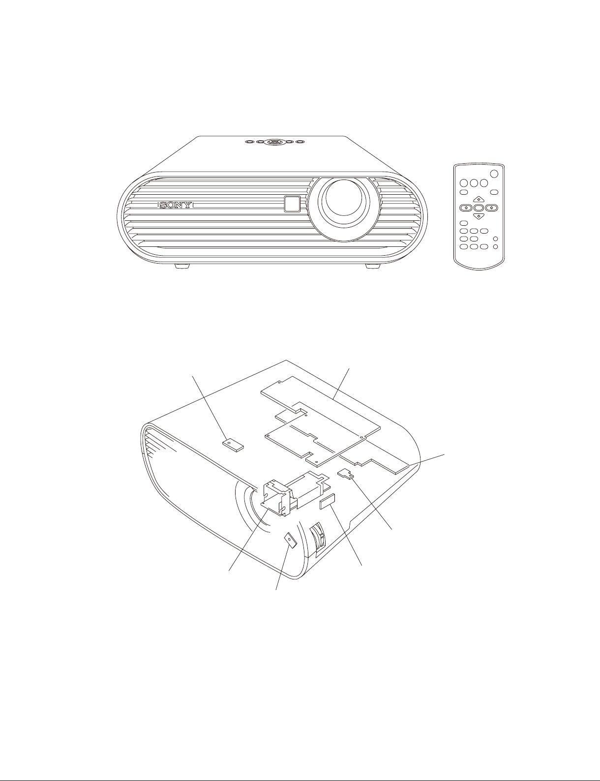
1-1. Appearance Figure
Section 1
Service Overview
1-2. Board Location
Door detection switch
Lamp power supply
Main
Power
Thermal sensor
Door detection switch
IR sensor
VPL-ES7
1-1
Page 8
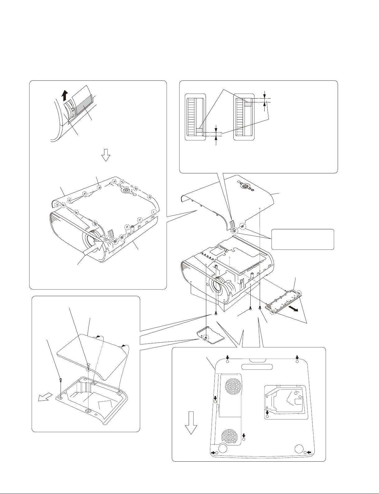
1-3. Disassembly
1-3-1. Upper Case Assembly
Zoom adjust gear knob
Press here strongly.
Remove the Upper case assembly
in the direction of the arrow.
Disengage the claws at
the 17 locations respectively.
Upper case assembly
Lower case pack
Caution :
Remove the upper case assembly from this corner.
When attaching the upper case assembly, attach it while
aligning with the lower case
starting from this corner.
pack
assembly
assembly
Upon completion of the upper
case assembly attachment,
check to see that the spacing
in the top is equal to the
Caution :
If the spacings in the top and bottom are not equal, go to
method of optical unit assembly and Focus/Zoom
(Refer to section 1-3-8. Steps 9 to 14.)
spacing in the bottom.
adjust assembly”.
Upper case assembly
These portions are fragile.
Be very careful not to
damage them.
Remove the filter
door in the direction
of the arrow .
“Assembling
Loosen screw.
Screw
(+P M3 x 6)
Front Side
of Unit
1-2
Lamp door
Lower case pack
assembly
Front Side
of Unit
Screw
Five screws
(+P M3 x 6)
(+P M3 x 6)
Two claws
VPL-ES7
Page 9
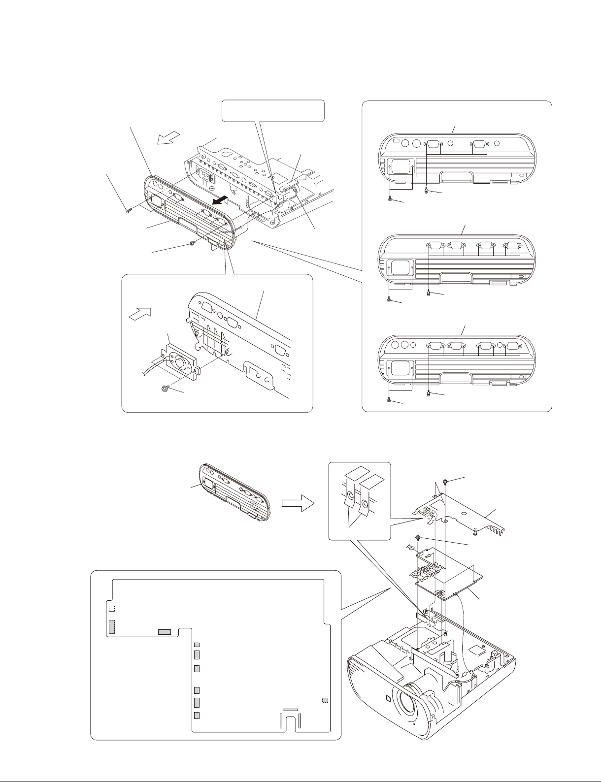
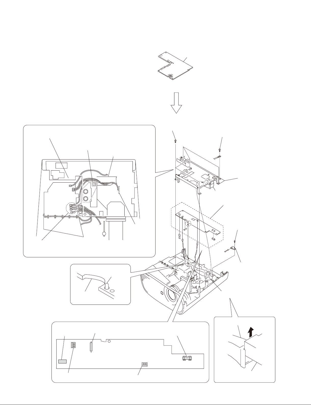
1-3-2. Rear Case Pack Assembly
Rear case pack assembly, etc.
Rear Side
Two screws
(+K 3 x 12)
VPL-EX7
Six hexagon
screws
of Unit
Rear Side
of Unit
Speaker
Route the speaker harness
under the MB bracket.
Rear case pack assembly
Main board
J11
Speaker harness
Rear case pack assembly
VPL-ES7
VPL-EX7IN
VPL-EX70
Rear case pack assembly
Four hexagon screws
Two screws (+K 3 x 12)
Rear case pack assembly
Eight hexagon screws
Two screws (+K 3 x 12)
Rear case pack assembly
1-3-3. Main Board
Rear case pack assembly,
etc.
(Refer to section 1-3-2, steps 1 to 4.)
J11
J17
J16
Two screws
(+PWH 3 x 6)
J26
J21
J20
Main board
Shield
Eight hexagon screws
Two screws (+K 3 x 12)
(+PWH 3 x 6)
Two screws
Shield
Three screws
(+PWH 3 x 6)
Main board
VPL-ES7
Remove the
twelve connectors.
J14
J19
J18
J23
J24 J22
J6
1-3
Page 10
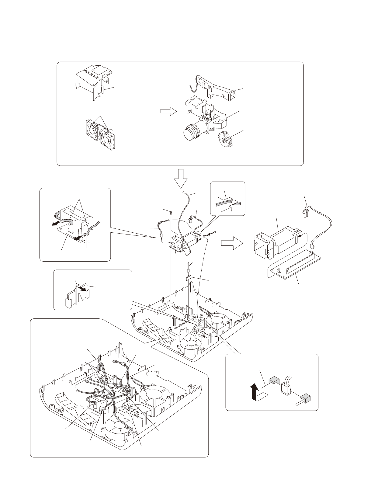
1-3-4. Power Board and Thermal Sensor Board
Check to see that the seven connectors are
protruding from the MB bracket.
Be careful that the harnesses must not override on
top of this port or must not be pinched by this portion.
Lamp nozzle assembly
Mai
n board
(Refer to section 1-3-3, steps 2 to 6.)
Five tapping screws
(PAN M3 x 7)
Screw
(+PSW M4 x 6)
MB bracket
Door detection
switch board
Caution :
When attaching the MB bracket, bind the four harnesses into the shape
of “U” and attaching them to the MB bracket.
Dowel
Power board
CN701
Miniature fuse-links (F602)
Fuse (H.B.C.)
(F601)
Fan
Power board
Tapping screw
(PAN M3 x 7)
J1
Thermal sensor board
Lamp nozzle assembly
Lamp nozzle assembly
1-4
CN605
Power board
CN603
Remove the three connectors.
Remove the fan in the
direction of the arrow.
VPL-ES7
Page 11
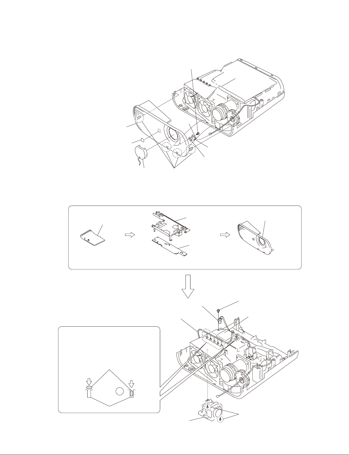
1-3-5. Front Case Assembly and IR Sensor Board
Tapping screw
(PAN M3 x 7)
Front case assembly
Logo
Lens cap
Four claws
1-3-6. Fan (Exhaust)-1
J7
IR sensor board
Sheet
Lamp door
(Refer to section 1-3-1, steps 2 to 4.)
(Refer to section 1-3-4, steps 2 to 8.)
Door detection switch
harness
Caution :
Because the harness has the shape of flat
cross-section, do not insert the harness into the
harness clamp section with excessive force.
Find out the direction in which the harness can
be inserted easily, and then insert the harness.
Harness
No good
Good
Lamp connector
assembly
MB bracket
Power board
Front
(Refer to section 1-3-5.)
case assembly
Screw
(+PWH 3 x 6)
Lamp box assembly
VPL-ES7
Harness clamp section
Lamp assembly
Loosen two screws.
1-5
Page 12
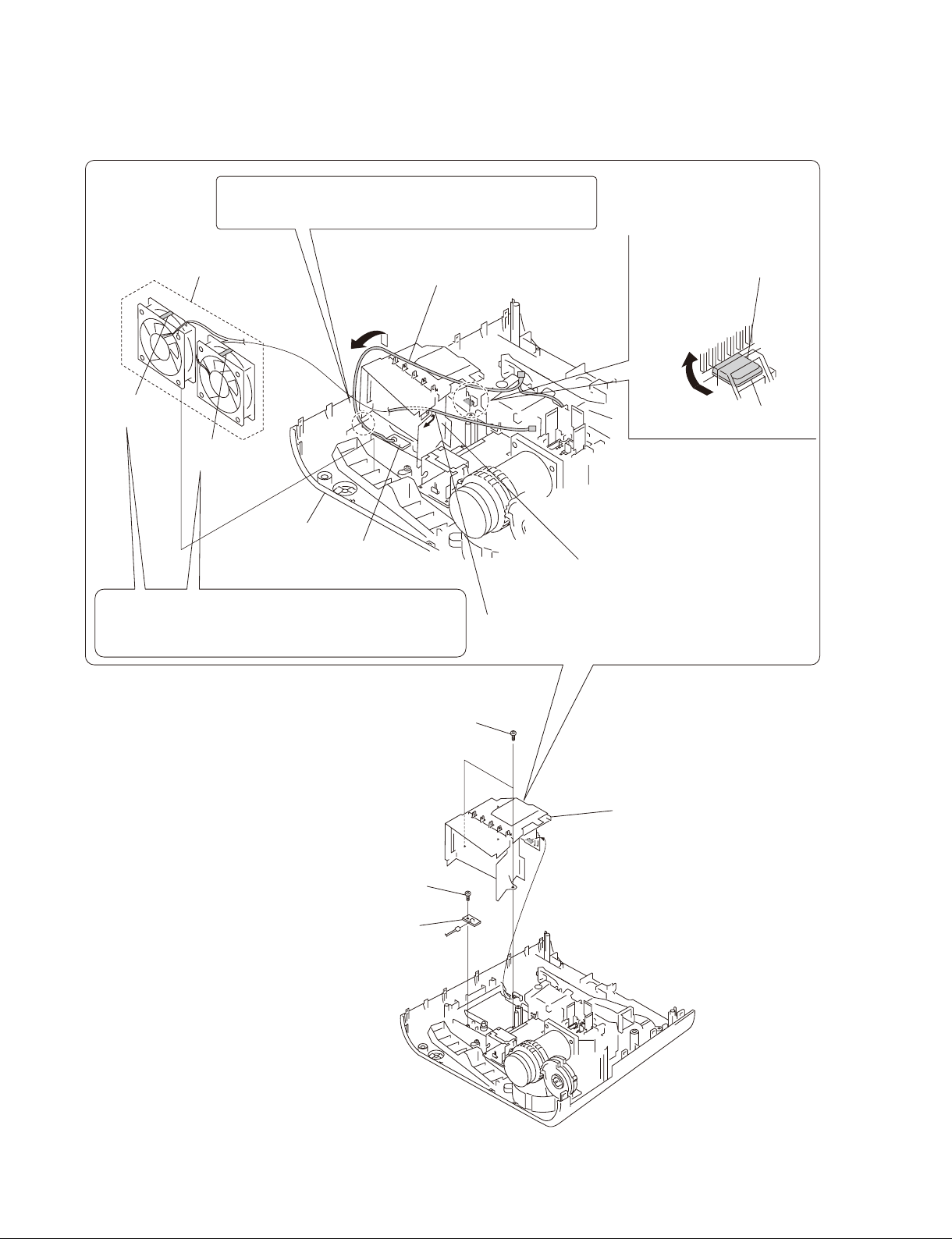
1-3-7. Fan (Exhaust)-2
Caution :
When attaching the lamp box assembly, insert the door detection
switch harness into the groove of the lower case pack assembly.
Fan (Exhaust)
80*25 AD0812HB/HB
Remove the door detection switch
harness in the direction of the arrow .
Remove the protrusion in the
direction of the arrow .
UB mark is
indicated.
HB mark is
indicated.
Lower case pack
assembly
Caution :
Two exhaust fans are the two different fans having the difference
characteristics. Be careful not to make mistake in choosing the
desired fan by confirming the indication on the fans.
Door detection
switch board
Two tapping screws
(PAN M3 x 7)
protrusion
Lamp box assembly
Remove the fan harness in the direction of the arrow .
1-6
Tapping screw
(PAN M3 x 7)
Door detection switch board
CN1
Lamp box assembly
VPL-ES7
Page 13
1-3-8. Optional Unit Assembly
Lamp box assembly
(Refer to section 1-3-6, steps 5 to 9) and
(refer to section 1-3-7, steps 1,2, 4 to 6.)
L
amp nozzle assembly
Lamp connector
assembly
CON thermal
145MM wire
Door detection
switch harness
Lamp nozzle assembly
Tapping screw
(PH W/FLA M3 x 10L PT ZN)
Three tapping screws
(PAN M3 x 7)
Optical unit
assembly
Caution :
When attaching the lamp nozzle assembly, route that harnesses
in between the lamp nozzle assembly and optical unit assembly.
Two tapping screws
(PAN M3 x 7)
Thermal sensor harness,
Fan harness
Two tapping screws
(PAN M3 x 7)
Focus/Zoom adjust
assembly
Assembling method of optical unit assembly and
Focus/Zoom adjust gears assembly
Attach the Focus/Zoom Adjust assembly into the two
dowels of the lower case pack assembly after rotating the
Focus/Zoom Adjust assembly as far as it can be rotated
in the direction of clockwise direction.
Lens: Rotate the Focus/Zoom gears in
the counter-clockwise direction as far
as it can be rotated.
Lower case pack assembly
Fix the Focus/Zoom Adjust assembly
tentatively with the screw.
Two dowels
Lens: Focus/Zoom gears
Zoom adjust gear
Focus adjust gear
Rotate the zoom adjust gear in the
counter-clockwise direction by one
tooth. Then, engage these gears
with the corresponding lens gears.
Attach the other screw while fixing
the gear position.
VPL-ES7
Tighten the screw finally that has
been tightened tentatively.
1-7
Page 14
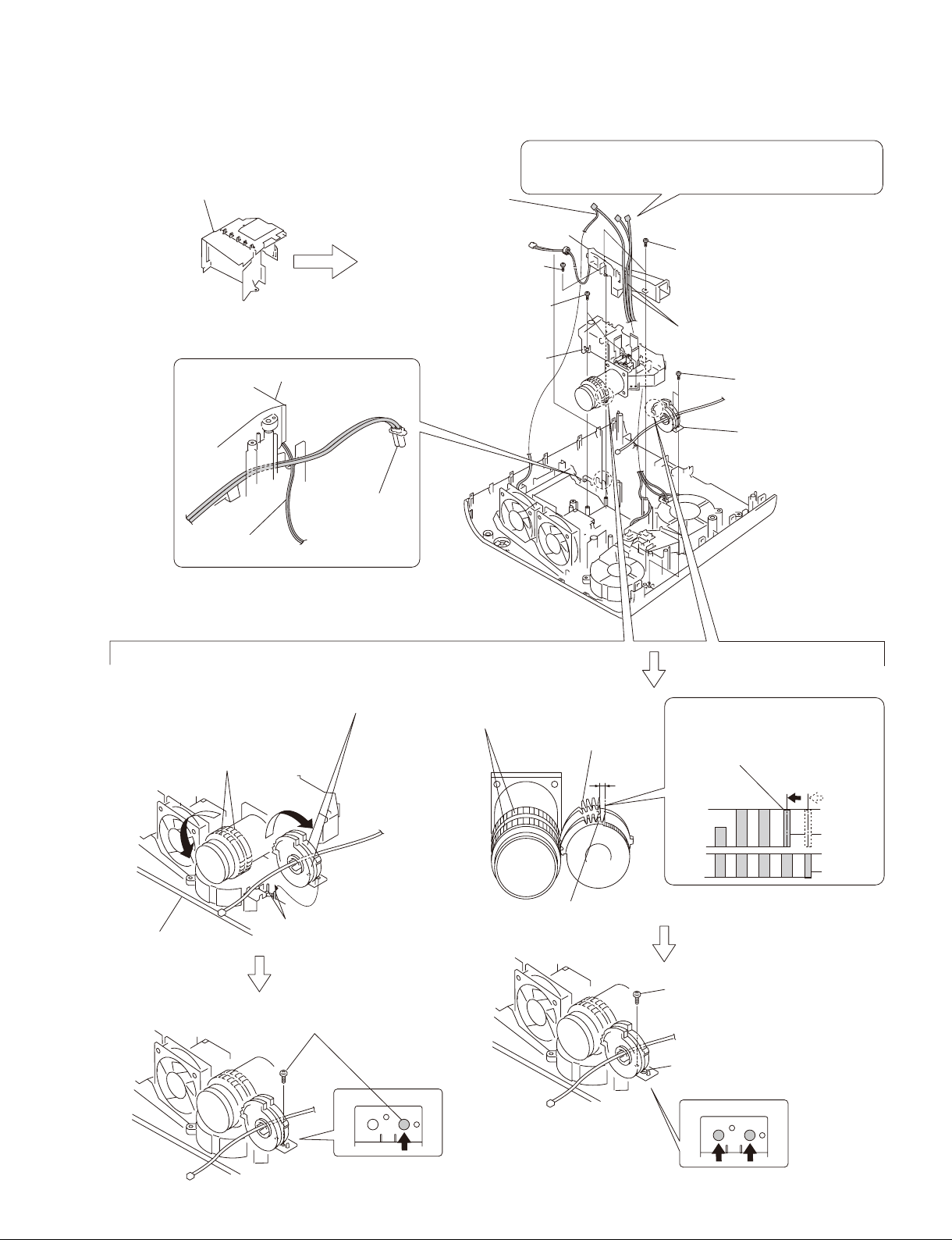
1-3-9. Lamp Power Supply
Fan (Exhaust)
80*25 AD0812HB/HB
Lamp box assembly
Lamp nozzle assembly
Optical unit assembly
Focus/Zoom adjust
assembly
(Refer to section 1-3-6, steps 5 to 9) and
(refer to section 1-3-7, steps 1 to 6.)
Two
harnesses
Lamp power supply
Claw
Door detection
switch board
Caution :
When re-assembling the machine,
route the respective harnesses and
wires at the specified locations as shown.
Route the Lamp connector
assembly
between them.
Two tapping screws
(PAN M3 x 7)
(Refer to section 1-3-8, steps 2 to 8.)
Mylar ballast
Door detection
switch board
Remove the lamp power supply
in the direction of the arrow .
X1
CN1
Mylar ballast
Lamp connector
assembly
Lamp power supply
Lamp power supply
1-8
Route the harness
through the hole of
this sheet.
Door detection switch board
VPL-ES7
Page 15
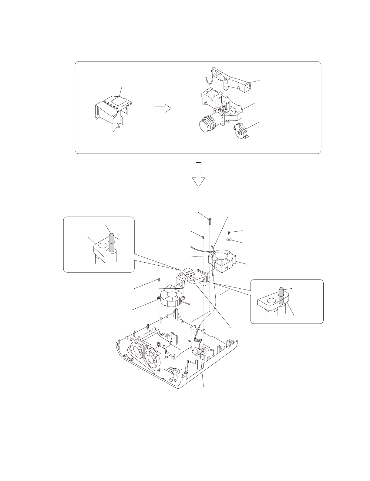
1-3-10. Fan
Lamp box assembly
Lamp nozzle assembly
Optical unit assembly
Focus/Zoom adjust
assembly
(Refer to section 1-3-6, steps 5 to 9) and
(refer to section 1-3-7, steps 1,2, 4 to 6.)
Dowel
Prism duct
Two tapping screws
(PH W/FLA M3 x 10L PT ZN)
Fan
70*70*25 240MM AB07012UB
Tapping screw
(PH W/FL M3 x 35 NI D-PT)
Two tapping screws
(PAN M3 x 7)
(Refer to section 1-3-8, steps 2 to 8.)
Harness
Tapping screw
(PAN M3 x 7)
Washer
Fan
75*75*30 145MM AB7512UB
Prism duct
Dowel
VPL-ES7
Prism duct
Thermal sensor board
1-9
Page 16
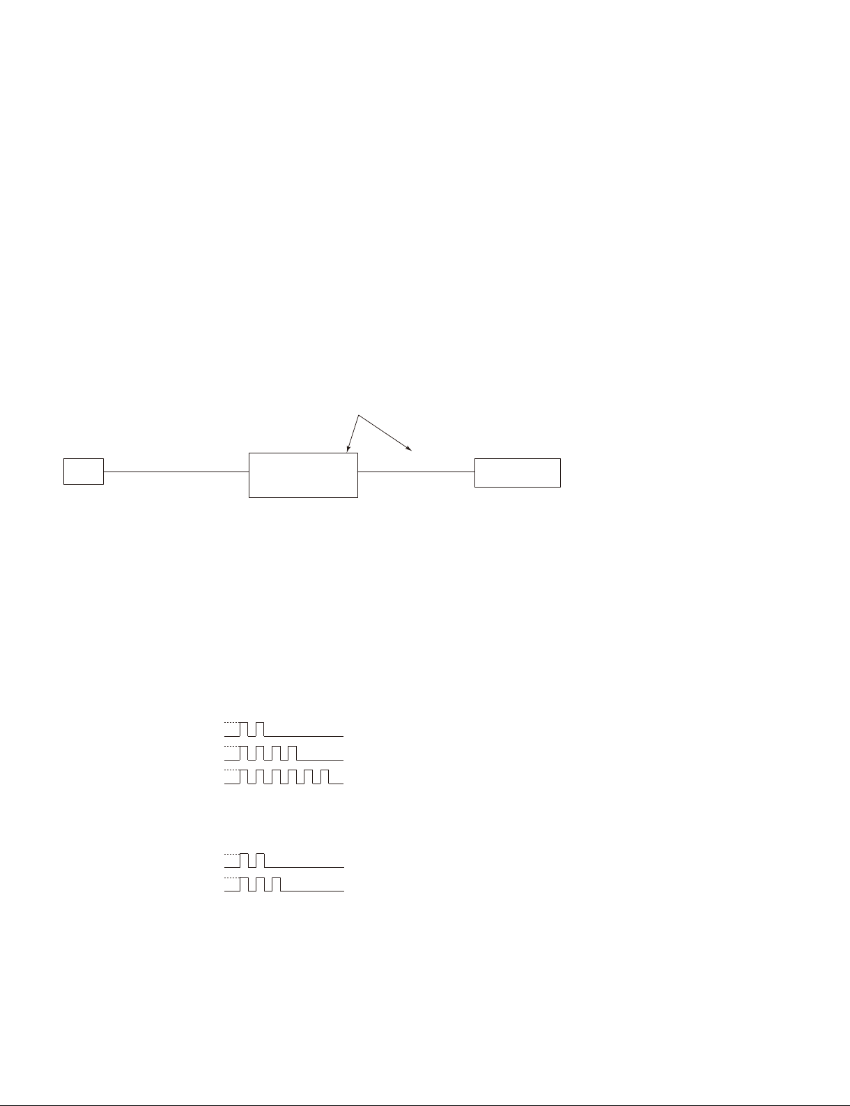
1-4. 3D GAMMA Service Tool Application Software
Feature:
The Ernie Service Tool is the application software for performing the tasks such as reading out and writing of the 3D GAMMA data on the projector that is connected to a PC via a communication function.
The Ernie Service Tool has the following features.
. It can read 3D GAMMA data from a set and save it in a fi le.
. It can write 3D GAMMA data in a PC into a set.
When the optical unit is replaced, write 3D GAMMA data recorded on the CD-ROM, which is supplied
together with the optical unit, into a set using the application software.
. VPL-ES7 set has not RS-232C terminal, use the QUICK ACCESS Assy.
. Remove the rubber cap on the upper left of the rear side of the unit.
QUICK ACCESS Assy
J12
Set
Main board CN
PC
RS-232C
Straight
cable
QUICK ACCESS
Dsub
Assy
9pin
(Parts No. A-1568-125-A)
CN 5P
CN J8
5pin
1-5. Indicator
The error status of the this units are indicated by the type of fl ashing of indicator. The top cover has the
ON/STANDBY indicator and the LAMP/COVER indicator. Various error contents are indicated by the
type of fl ashing of indicator. For details of the types of indicator fl ashing and the error statuses, refer to
the list shown below.
ON/STANDBY Indicator (Red fl ashing)
Error Name
Temperature Error
Fan Error
Power Error
LAMP/COVER Indicator (Orange fl ashing)
Cover Error
Lamp Error
Flash Frequency
ON
OFF
ON
OFF
ON
OFF
Flash FrequencyError Name Status
ON
OFF
ON
OFF
2 Times
4 Times
6 Times
2 Times
3 Times
Status
The temperature of the equipment is high.
Each fan dose not work normally.
The power is not turned on correctly.
The lamp or filter cover is opened.
The UHP lamp is not lighting.
1-10
VPL-ES7
Page 17

1-6. Circuit Description
Main Board:
Video input block
*1
The video input has two channels: Composite video and S-Video. The 2-channel inputs are sent directly to
the video processor, and converted to the digital data by the built-in AD converter of the video processor.
PC input block
There are two channels: Input A and Input B, one of which is selected with the toggle switch. The selected
output is input to the video processor and the video buffer. At the video processor, the signal is converted
to the digital data by the built-in AD converter. The signal input to the video buffer is output as a monitor
out.
To Input A, PC signals, component signals, and video GBR signals can be input. To Input B, only PC
signals can be input. (VPL-EX7IN can input only PC signals.)
Audio input block
*1
Stereo mini jack input. The L/R input is synthesized internally into a monaural signal. The signal is synthesized by a resistance, so the output level varies between the case where only one channel is input and
the case where both channels are input. The standard is prescribed under the condition where only one
channel is input.
Monitor output block (PC)
The signals input to Input A and Input B are output. The signal of the channel that is selected with the
input toggle switch is output. No output is made if Video or S-Video is selected.
Monitor output block (Audio)
*1
The signal input to the audio input is output. This output is variable with the volume control. If a cable is
connected to this connector, the output from the built-in speaker stops.
Video processor & System control block
PW-190 made by Pixelworks Inc. is used. This IC performs pixel number conversion, aspect conversion,
and OSD addition to the input signals. This IC also controls brightness, sharpness, chroma, and hue.
In addition, the built-in CPU controls the system.
Control target: Control panel, OSD display, lamp cover switch, fi lter door switch, LED control, serial
control
LCD timing generator (DSD) block
The IC for LCD panel made by Sony is used. This IC generates the timing for driving the LCD panel.
This uses the method that inverts the driving direction for each frame. In addition to timing generation,
this IC performs white balance adjustment, gamma adjustment, and color shading adjustment.
LCD driver block
The drive IC for LCD panel made by Sony is used. This drives the LCD panel in a 12-phase drive method
at the timing generated by the timing generator IC. The GBR and the circuit for three channels are
equipped.
*1: Not valid for VPL-EX7IN.
VPL-ES7
1-11
Page 18

FAN control, Thermal sensor block
The IC with the built-in FAN control and thermal sensor function is used.
. FAN control
This detects the FG of the FAN, and controls the number of rotations. The number of rotations is set in
accordance with the internal temperature.
. Thermal sensor
The thermal sensor is placed at the lower part of the power board, and the internal temperature is mea-
sured.
Ballast drive block
This drives the ballast in synchronization with the input signal. The synchronous circuit is formed by the
microprocessor.
When the lamp mode is standard, ballast is driven in synchronization with the frequency 1.5 times higher
than that of the input signal. When the lamp mode is high, the ballast is driven in synchronization with the
input signal.
RS232C block
This is used to connect the PW-190 via the RS232C driver/receiver IC. Because the number of serial ports
is limited on the PW-190, the RS232C and network cannot be used at the same time. The RS232C block
is equipped with the circuit that switches them.
Sensor Board:
The sensor boards include the thermal sensor board, lamp cover switch board, fi lter door switch board,
and IR sensor board.
Power Board:
This supplies the lamp power and the system power. For the system power, +15.25 V, +12 V, and +5 V
are output, and the circuit power is generated on the main board.
1-12
VPL-ES7
Page 19

1-7. Replacing Fuse
w
The fuse is essential parts for safe operation.
Replace the components with Sony parts whose part numbers appear in the manual published by Sony. If
the components are replaced with any parts other than the specifi ed ones, this may cause a fi re or electric
shock.
c
If the fuse is replaced while the main power is kept on, this may cause electric shock.
Before replacing the fuse, not only turn off the POWER switch but also disconnect the AC power cord
that is connected to the AC IN connector.
This unit is equipped with fuses.
The fuses blow if an excessive current fl ows due to abnormality inside the equipment. If fuses blow, turn
off the main power of the equipment once, and inspect inside of the equipment and remove the cause of
excessive current. After that, replace the fuses. (Refer to Section 1-3-4.)
Board Ref. No. (Address) Part No./Name
POWER F601 ! 1-576-233-51 Fuse 6.3 A, 250 V
F602 ! 1-576-973-11 Fuse 2 A, 600 V
Miniature fuse-links (F602)
Power board
Fuse (H.B.C.)
(F601)
VPL-ES7
1-13
Page 20

1-8. Connecting/Disconnecting the Flexible Card Wire
m
. Be very careful not to fold the fl exible card wire. Life of fl exible card wire will be signifi cantly short-
ened if it is folded.
. The fl exible card wire has the conduction side and the insulation side. If the conduction side and the
insulation side are connected in the wrong direction, the circuit will not function.
. Insert the fl exible card wire straight.
. Ensure that the conduction surface of the fl exible card wire is not contaminated.
Disconnecting
Life portions A of the connector to unlock, and disconnect the fl exible card wire.
Connecting
1. Insert the fl exible card wire fi rmly as far as it will go, with the conduction side up.
2. Push portions A of the connector to lock.
Disconnecting Connecting
Connector
Portion A
Portion A
Flexible card wire
Connector
Conduction
side
Flexible card wire
1-9. Lead-free Solder
Boards requiring use of lead-free solder are printed with a lead free mark (LF) indicating the solder
contains no lead.
(Caution: Some printed circuit boards may not come printed with the lead free mark due to their particular
size.)
: LEAD FREE MARK
m
. Be sure to use the lead-free solder for the printed circuit board printed with the lead free mark.
. The lead-free solder melts at a temperature about 40 dC higher than the ordinary solder, therefore, it is
recommended to use the soldering iron having a temperature regulator.
. The ordinary soldering iron can be used but the iron tip has to be applied to the solder joint for a slightly
longer time. The printed pattern (copper foil) may peel away if the heated tip is applied for too long, so
be careful.
1-14
VPL-ES7
Page 21

Section 2
Electrical Adjustments
2-1. Preparation
2-1-1. Required Equipment
. NTSC, PAL, SECAM component signal generator Tektronix TG2000 + AVG1 (option module) +
AWVG1 (option module) or equivalent
. VG (programmable video signal generator) VG828 or equivalent
. Chroma meter KONICA MINOLTA CL-200
2-1-2. How to Enter the Service Mode
1. Power on the projector.
2. Push the switches on the remote controller or controller panel as below.
[Enter] → [Enter] → [&] → [Enter] key
3. Service mode menu will appear on the screen.
2-2. Adjustment of Main Board When it is Replaced
2-2-1. Save the Optical Data and Replacement
1. Try to read the optical data from the faulty unit using the Emie Service tool. If succeeded in reading,
replacement of the EEPROM is not necessary but the V COM Adjustment should be performed.
(Refer to “2-5 V COM Adjustment”.)
2. If the optical data could not be read from the faulty unit in step 1, remove the IC (EEPROM) from the
faulty board and replace the IC (EEPROM) of the new board with the removed one.
Reference number: U33, U48 (ES7), U20 (EX7/EX7IN/EX70)
3. Run the RGB and YUV calibration.
VPL-ES7
2-1
Page 22

2-3. EEPROM Replacement
EEPROM of the main board contains the following alignment data
System EEPROM (32 kbits) (U33)
. V com setting
. Color temperature
. RGB gain and offset for PC
. YUV gain and offset for YPbPr
. OSD setting
Gamma EEPROM (256 kbits)
(U48: ES7, U20: EX7/EX7IN/EX70)
. 3D gamma
. Panel gamma
Gamma EEPROM
(U20)
System EEPROM(U33)
EX7/EX7IN/EX70 Main Board
Gamma EEPROM
(U48) (Side B)
System EEPROM(U33)
ES7 Main Board
2-4. ADC Calibration
2-4-1. RGB Alignment Procedure
1. Power on the projector.
2. Input the following signal from the signal generator to the INPUT A connector.
Timing: VPL-EX7/EX7IN/EX70: 1024 x 768 : 60 Hz
VPL-ES7: 800 x 600 : 60 Hz
Pattern: 16 gray pattern
If the pattern shown in Fig. 1 is not available, the pattern shown in Fig. 3 can be used for the adjust-
ment. Use the signal shown in Fig. 2 to run APA. Then, input the signal shown in Fig. 3.
Fig.1 Fig.2 Fig.3
2-2
VPL-ES7
Page 23

3. Enter the service mode and change to page “ADC Calibration”.
4. Press [*] key to run calibration.
5. When calibration is executed, the screen brightness changes for approx. 5 seconds. After that, the
screen brightness, the RGB Offset data and the RGB Gain data become stabilized.
P4 ADC calibration
RGB Calibrate
YUV Calibrate
RGB Offset
RGB Gain
YUV Offset
YUV Gain
R Offset
G Offset
B Offset
R Gain
G Gain
B Gain
< or >
< or >
119 128 102
67 65 57
129 109 108
81 71 63
129
109
108
81
71
63
ES7
<< >>ADC calibration
RGB Calibrate
YUV Calibrate
RGB Offset
RGB Gain
YUV Offset
YUV Gain
R Offset
G Offset
B Offset
R Gain
G Gain
B Gain
138 88 122
62 55 60
147 68 144
71 27 69
EX7/EX7IN/EX70
< or >
< or >
138
88
122
52
55
60
2-4-2. YUV Alignment Procedure
1. Power on the projector.
2. Input the following signal from the signal generator to the INPUT A connector.
Timing: 480P
Pattern: SMPTE color bar
3. Enter the service mode and change to page “ADC Calibration”.
4. Press [*] key to run calibration.
5. When calibration is executed, the screen brightness changes for approx. 5 seconds. After that, the
screen brightness, the YUV Offset data and the YUV Gain data become stabilized.
P4 ADC calibration
RGB Calibrate
YUV Calibrate
RGB Offset
RGB Gain
YUV Offset
YUV Gain
R Offset
G Offset
B Offset
R Gain
G Gain
B Gain
VPL-ES7
< or >
< or >
119 128 102
67 65 57
129 109 108
81 71 63
129
109
108
81
71
63
ES7
<< >>ADC calibration
RGB Calibrate
YUV Calibrate
RGB Offset
RGB Gain
YUV Offset
YUV Gain
R Offset
G Offset
B Offset
R Gain
G Gain
B Gain
138 88 122
62 55 60
147 68 144
71 27 69
EX7/EX70
< or >
< or >
138
88
122
52
55
60
2-3
Page 24

2-5. V COM Adjustment
. By the Ernie Service tool, the V COM data is not replaced. Therefore, perform the V COM Adjustment
when optical data is replaced by the Ernie Service tool.
. When the EEPROM is replaced, the V COM data is inherited so that the V COM adjustment is not
necessary.
If fl icker is signifi cant on the screen, perform the V COM adjustment.
Procedure: VPL-ES7
1. Input the 100 % fl at-fi eld signal to the INPUT A connector and allow the warm-up of 10 minutes
aging at a minimum.
2. Enter the service mode and change to page 4 “Vcom & Misc” page.
3. Input the XGA, R-single color, 30 %, single-line ON/OFF signal.
4. Move the cursor key until it is positioned at Vcom-R Normal.
5. Adjust the V com-R Normal value until fl icker is reduced to minimal by [*], [&] key.
6. Change the input signal to the XGA, G-single color, 30 %, single-line ON/OFF signal.
7. Move the cursor key until it is positioned at Vcom-G Normal.
8. Adjust the V com-G Normal value until fl icker is reduced to minimal by [*], [&] key.
9. Change the input signal to the XGA, B-single color, 30 %, single-line ON/OFF signal.
10. Move the cursor key until it is positioned at Vcom-B Normal.
11. Adjust the V com-B Normal value until fl icker is reduced to minimal by [*], [&] key.
12. Reverse the “Image Flip” upside-down and right-to-left, and repeat the above adjustment procedure
from step 2 to step 11.
Vcom & Misc.
<< >>
Vcom-R Normal
Vcom-G Normal
Vcom-B Normal
Vcom-R Flip
Vcom-G Flip
Vcom-B Flip
EDID Write Protect
ROM Version:
82
89
83
88
88
88
ON
0.06
2-4
VPL-ES7
Page 25

Procedure: VPL-EX7/EX7IN/EX70
1. Input the 100 % fl at fi eld signal to the INPUT A connector and allow the warm-up of 10 minutes
aging at a minimum.
2. Enter the service mode and change to page 4 to select “Vcom & Misc”.
3. Input the XGA, G-single color, 80 %, fl at-fi eld signal.
4. Move the cursor key until it is positioned at Vcom-G Normal.
5. Adjust the V com-G Normal value until fl icker is reduced to minimal by [*], [&] key.
6. Change the input signal to the XGA, R-single color, 80 %, fl at-fi eld signal.
7. Move the cursor key until it is positioned at Vcom-R Normal.
8. Adjust the V com-R Normal value until fl icker is reduced to minimal by [*], [&] key.
9. Change the input signal to the XGA, B-single color, 80 %, fl at-fi eld signal.
10. Move the cursor key until it is positioned at Vcom-B Normal.
11. Adjust the V com-B Normal value until fl icker is reduced to minimal by [*], [&] key.
12. Reverse the “Image Flip” upside-down and right-to-left, and repeat the above adjustment procedure
from step 2 to step 11.
Vcom & Misc.
<< >>
Vcom-R Normal
Vcom-G Normal
Vcom-B Normal
Vcom-R Flip
Vcom-G Flip
Vcom-B Flip
94
90
92
83
83
83
EDID Write Protect
ROM Version:
ON
1.00
VPL-ES7
2-5
Page 26

2-6. White Balance Adjustment
Preparation before adjustment
Input the 100 % fl at fi eld signal to the INPUT A connector and allow the warm-up of 10 minutes aging at a mini-
mum.
2-6-1. HIGH Mode of PC
1. Input the 80 % fl at fi eld computer signal to the INPUT-A connector.
2. Set the picture quality mode to STANDARD, and set color temperature to HIGH.
3. The target chromaticity (x, y) is (0.282, 0.299).
4. Enter the service mode and change to CXD9809-Page 2 (ES7) or White Balance 1 page (EX7/EX7IN/EX70).
5. Adjust the PC Hi Gain-R and PC Hi Gain-B until the target chromaticity (x, y) as shown is obtained.
6. Repeat steps 2 to 5 until the chromaticity (x ?0.002, y ?0.002) with reference to the target chromaticity (x, y)
is obtained.
P1-2 CXD9809-page2
PC Hi Gain-R
PC Hi Gain-G
PC Hi Gain-B
PC Hi Bias-R
PC Hi Bias-G
PC Hi Bias-B
PC Lo Gain-R
PC Lo Gain-G
PC Lo Gain-B
PC Lo Bias-R
PC Lo Bias-G
PC Lo Bias-B
112
83
128
0
0
0
128
78
93
0
0
0
ES7
White Balance 1
<< >>
PC Hi Gain-R
PC Hi Gain-G
PC Hi Gain-B
PC Hi Bias-R
PC Hi Bias-G
PC Hi Bias-B
PC Lo Gain-R
PC Lo Gain-G
PC Lo Gain-B
PC Lo Bias-R
PC Lo Bias-G
PC Lo Bias-B
433
410
494
- 5
0
- 6
478
430
452
5
0
- 6
EX7/EX7IN/EX70
2-6-2. MIDDLE Mode of PC
1. Input the 80 % fl at fi eld computer signal to the INPUT-A connector.
2. Set the picture quality mode to STANDARD, and set color temperature to MIDDLE.
3. The target chromaticity (x, y) is (0.390, 0.321).
4. Enter the service mode and change to CXD9809-Page4 (ES7) or White Balance 3 page (EX7/EX7IN/EX70).
5. Adjust the PC Mid Gain-R and PC Mid Gain-B until the target chromaticity (x, y) is obtained.
6. Repeat steps 2 to 5 until the chromaticity (x ?0.002, y ?0.002) with reference to the target chromaticity (x, y)
is obtained.
P1-4 CXD9809-page4
PC Mid Gain-R
PC Mid Gain-G
PC Mid Gain-B
PC Mid Bias-R
PC Mid Bias-G
PC Mid Bias-B
Video Mid Gain-R
Video Mid Gain-G
Video Mid Gain-B
Video Mid Bias-R
Video Mid Bias-G
Video Mid Bias-B
2-6
125
100
126
127
100
122
0
0
0
0
0
0
ES7
White Balance 3
<< >>
PC Mid Gain-R
PC Mid Gain-G
PC Mid Gain-B
PC Mid Bias-R
PC Mid Bias-G
PC Mid Bias-B
Video Mid Gain-R
Video Mid Gain-G
Video Mid Gain-B
Video Mid Bias-R
Video Mid Bias-G
Video Mid Bias-B
451
445
486
0
0
0
466
445
508
35
0
44
EX7/EX7IN/EX70
VPL-ES7
Page 27

2-6-3. LOW Mode of PC
1. Input the 80 % fl at fi eld computer signal to the INPUT A connector.
2. Set the picture quality mode to STANDARD, and set color temperature to LOW.
3. The target chromaticity (x, y) is (0.312, 0.334).
4. Enter the service mode and change to CXD9809-Page 2 (ES7) or White Balance 1 page (EX7/EX7IN/EX70).
5. Adjust the PC Lo Gain-R and PC Lo Gain-B until the target chromaticity (x, y) is obtained.
6. Repeat steps 2 to 5 until the chromaticity (x ?0.002, y ?0.002) with reference to the target chromaticity (x, y)
is obtained.
P1-2 CXD9809-page2
PC Hi Gain-R
PC Hi Gain-G
PC Hi Gain-B
PC Hi Bias-R
PC Hi Bias-G
PC Hi Bias-B
PC Lo Gain-R
PC Lo Gain-G
PC Lo Gain-B
PC Lo Bias-R
PC Lo Bias-G
PC Lo Bias-B
112
83
128
0
0
0
128
78
93
0
0
0
ES7
White Balance 1
<< >>
PC Hi Gain-R
PC Hi Gain-G
PC Hi Gain-B
PC Hi Bias-R
PC Hi Bias-G
PC Hi Bias-B
PC Lo Gain-R
PC Lo Gain-G
PC Lo Gain-B
PC Lo Bias-R
PC Lo Bias-G
PC Lo Bias-B
433
410
494
- 5
0
- 6
478
430
452
5
0
- 6
EX7/EX7IN/EX70
2-6-4. HIGH Mode of VIDEO
1. Input the 80 % fl at fi eld 480/60i or 575/50i signal to the INPUT A connector.
2. Set the picture quality mode to STANDARD, and set color temperature to HIGH.
3. The target chromaticity (x, y) is (0.282, 0.299).
4. Enter the service mode and change to CXD9809-Page 3 (ES7) or White Balance 2 page (EX7/EX70).
5. Adjust the PC Hi Gain-R and PC Hi Gain-B until the target chromaticity (x, y) is obtained.
6. Repeat steps 2 to 5 until the chromaticity (x ?0.002, y ?0.002) with reference to the target chromaticity (x, y)
is obtained.
P1-3 CXD9809-page3
Video Hi Gain-R
Video Hi Gain-G
Video Hi Gain-B
Video Hi Bias-R
Video Hi Bias-G
Video Hi Bias-G
Video Lo Gain-R
Video Lo Gain-G
Video Lo Gain-B
Video Lo Bias-R
Video Lo Bias-G
Video Lo Bias-B
117
84
128
0
0
0
128
79
88
0
0
0
ES7
White Balance 2
<< >>
Video Hi Gain-R
Video Hi Gain-G
Video Hi Gain-B
Video Hi Bias-R
Video Hi Bias-G
Video Hi Bias-G
Video Lo Gain-R
Video Lo Gain-G
Video Lo Gain-B
Video Lo Bias-R
Video Lo Bias-G
Video Lo Bias-B
442
410
512
19
0
38
503
430
475
35
0
26
EX7/EX70
VPL-ES7
2-7
Page 28

2-6-5. MIDDLE Mode of VIDEO
1. Input the 80 % fl at fi eld 480/60i or 575/50i signal to the INPUT A connector.
2. Set the picture quality mode to STANDARD, and set color temperature to MIDDLE.
3. The target chromaticity (x, y) is (0.390, 0.321).
4. Enter the service mode and change to CXD9809-Page 4 (ES7) or White Balance 3 page (EX7/EX70).
5. Adjust the PC Mid Gain-R and PC Mid Gain-B until the target chromaticity (x, y) is obtained.
6. Repeat steps 2 to 5 until the chromaticity (x ?0.002, y ?0.002) with reference to the target chromaticity (x, y)
is obtained.
P1-4 CXD9809-page4
PC Mid Gain-R
PC Mid Gain-G
PC Mid Gain-B
PC Mid Bias-R
PC Mid Bias-G
PC Mid Bias-B
Video Mid Gain-R
Video Mid Gain-G
Video Mid Gain-B
Video Mid Bias-R
Video Mid Bias-G
Video Mid Bias-B
125
100
126
0
0
0
127
100
122
0
0
0
ES7
White Balance 3
<< >>
PC Mid Gain-R
PC Mid Gain-G
PC Mid Gain-B
PC Mid Bias-R
PC Mid Bias-G
PC Mid Bias-B
Video Mid Gain-R
Video Mid Gain-G
Video Mid Gain-B
Video Mid Bias-R
Video Mid Bias-G
Video Mid Bias-B
451
445
486
0
0
0
466
445
508
35
0
44
EX7/EX70
2-6-6. LOW Mode of VIDEO
1. Input the 80 % fl at fi eld 480/60i or 575/50i signal to the INPUT A connector.
2. Set the picture quality mode to STANDARD, and set color temperature to LOW.
3. The target chromaticity (x, y) is (0.312, 0.224).
4. Enter the service mode and change to CXD9809-Page 3 (ES7) or White Balance 2 page (EX7/EX70).
5. Adjust the PC Lo Gain-R and PC Lo Gain-B until the target chromaticity (x, y) is obtained.
6. Repeat steps 2 to 5 until the chromaticity (x ?0.002, y ?0.002) with reference to the target chromaticity (x, y)
is obtained.
P1-3 CXD9809-page3
Video Hi Gain-R
Video Hi Gain-G
Video Hi Gain-B
Video Hi Bias-R
Video Hi Bias-G
Video Hi Bias-G
Video Lo Gain-R
Video Lo Gain-G
Video Lo Gain-B
Video Lo Bias-R
Video Lo Bias-G
Video Lo Bias-B
2-8
117
128
128
84
79
88
0
0
0
0
0
0
ES7
White Balance 2
<< >>
Video Hi Gain-R
Video Hi Gain-G
Video Hi Gain-B
Video Hi Bias-R
Video Hi Bias-G
Video Hi Bias-G
Video Lo Gain-R
Video Lo Gain-G
Video Lo Gain-B
Video Lo Bias-R
Video Lo Bias-G
Video Lo Bias-B
442
410
512
19
0
38
503
430
475
35
0
26
EX7/EX70
VPL-ES7
Page 29

2-7. Others
2-7-1. Note When Replacing the Main Board
The new Main board of VPL-ES7 is shipped with the 3D Gamma set to OFF.
After replacing the Main board and upon completion of adjustment, set the 3D Gamma setting to ON.
For the VPL-EX7/EX7IN/EX70, the following work is not necessary since the projector is shipped from
the factory with the 3D Gamma set to ON.
1. Enter the Factory Mode and display page 1.
2. Move the cursor to DELUT SW.
3. Operate the [*] key and set the 3D Gamma setting to ON.
P1-1 CXD9809-page1
TGHST Phase Hi
TGHST Phase Lo
SHSH1
TGHST Position
DEHPF On
DEHPF AAC
DEHPF TAP
DEUSC On
3D GammaSubCont
3D GammaSubBrt
DELUT SW
DEUF SW
0
111
31
18
ON
ON
3
OFF
8
50
OFF
ON
How to Enter the Factory Mode
1. Power on the projector.
2. Push the switches on the remote controller or controller panel as below.
[Enter] → [Enter] → [&] → [PIC|MUTING] key
3. Factory mode menu will appear on the screen.
n
In the factory mode, do not enter any items except the specifi ed one because the data cannot be returned
back to the original value if it is changed once.
VPL-ES7
2-9
Page 30

2-7-2. Status Information
The error status count is displayed.
P6 Error Count
Lamp can’t be
Light on
Fan operation
Abnormal
Thermal Sensor
Abnormal
Temperature
Abnormal
Fan Controller
Abnormal
Door switch open
Power level
Abnormal
Power Off
Abnormal
Lamp error
Fan 1 error
Fan 2 error
Fan 3 error
Fan 4 error
Sensor 1 open error
Sensor 2 open error
Sensor 1 short error
Sensor 2 short error
Temperature 1 error
Temperature 2 error
Fan IC I2C error
LampCovOpen in normal
FilterCovOpen in normal
Power error in normal
3540 Init error
System Crash
Reset error count
2-7-3. ADC Calibration Value
. RGB Offset: Offset value of computer signal
. RGB Gain: Gain adjustment of computer signal
. YUV Offset: Offset value of video signal
. YUV Gain: Gain adjustment of video signal
0
0
0
0
0
0
0
0
0
0
0
0
0
0
0
0
0
< or >
ES7
<< >>Error Count
Lamp error
Fan 1 error
Fan 2 error
Fan 3 error
Fan 4 error
Sensor 1 open error
Sensor 2 open error
Sensor 1 short error
Sensor 2 short error
Temperature 1 error
Temperature 2 error
Fan IC I2C error
LampCovOpen in normal
FilterCovOpen in normal
Power error in normal
3540 Init error
System Crash
Reset error count
EX7/EX7IN/EX70
0
0
0
0
0
0
0
0
0
0
0
0
0
0
0
0
0
< or >
P4 ADC calibration
RGB Calibrate
YUV Calibrate
RGB Offset
RGB Gain
YUV Offset
YUV Gain
R Offset
G Offset
B Offset
R Gain
G Gain
B Gain
100 124 121
164 222 164
< or >
< or >
69 61 65
93 105 93
100
124
121
69
61
65
2-10
VPL-ES7
Page 31

2-8. Memory Structure
Set memory Set memory Set memory
1
2
Status
Memory
3
Picture
Memory
4
W/B
Memory
5
Aspct Memory
6
Common
Memory
7
VPL-ES7
No.01 No.01 Status memory
No.02 No.02
No.03 No.03
No.04 No.04
No.05 No.05
--- --No.50 No.50
No.55 No.55
No.56 No.56
No.60 No.60
No.61 No.61
No.63 No.63
Dynamic Dynamic
Standard Standard
Video
S-Video
Input-A
Input-B
Component
Computer
Other than
Computer
Video, S-Video
Input-A
Input-B
Smart APA
(Computer only)
Volume Volume
Auto Input Search Auto Input Search
Input-A Signal Sel. *2 Input-A Signal Sel. *2
Color System *2
(Video/S-Video Only)
Power Saving Power Saving
IR Receiver IR Receiver
Panel Key Lock Panel Key Lock
Status Status
Language Language
Menu Position Menu Position
Start Up Image Start Up Image
Auto Keystone *1 Auto Keystone *1
Keystone Keystone
Image Flip Image Flip
Background Background
Lamp Mode Lamp Mode
High Altitude High Altitude
Security Lock Security Lock
CC Display *2 CC Display *2
FLASH ROM EEP ROM
Game Game
Living Living
Cinema Cinema
Presentation Presentation
Dynamic Dynamic
Standard Standard
Game Game
Living Living
Cinema Cinema
Presentation Presentation
Dynamic Dynamic
Standard Standard
Game Game
Living Living
Cinema Cinema
Presentation Presentation
Dynamic Dynamic
Standard Standard
Game Game
Living Living
Cinema Cinema
Presentation Presentation
Dynamic Dynamic
Standard Standard
Game Game
Living Living
Cinema Cinema
Presentation Presentation
High High
Mid Mid
Low Low
High High
Mid Mid
Low Low
No.1 No.1 Aspect memory
No.2 No.2
No.03 No.03
No.04 No.04
No.05 No.05
--- --No.50 No.50
No.55 No.55
No.56 No.56
No.60 No.60
No.61 No.61
No.63 No.63
No.21 No.21
No.22 No.22
No.23 No.23
--- --No.50 No.50
No.55 No.55
No.56 No.56
No.60 No.60
No.61 No.61
No.63 No.63
Status
Memory
Picture
Memory
W/B
Memory
Aspct Memory
Common
Memory
Video/Svideo
Input-A/Input-B
/Component
Video
S-Video
Input-A
Input-B
Component
Computer
Other than
Computer
Video, S-Video
Input-A
Input-B
Smart APA
(Computer only)
Color System *2
(Video/S-Video Only)
Direct Power OnDirect Power On
*1 : VPL-EX70 only
*2 : Not valid for VPL-EX7IN.
Picture memory
W/B memory
Common Memory
CPU RAM
2-11
Page 32

Memory structure of this model consists of the followings.
1 Set memory
2 Status memory
3 Picture memory
4 W/B memory
5 Aspct memory
6 Common memory
7 FLASH ROM/EEPROM
*
* The gamma memory is realized by giving offset to the Contrast and Brightness output values to the
devices in the gamma mode function.
Flow of data is described briefl y. When the power plug is connected to the wall outlet for the fi rst time
(Standby state), all data that are stored in the internal ROM are written in the NVM (non-volatile memory). When the POWER is turned ON, all the status memory data and other memory data that are required
for the present picture are selected from each memory block and expanded in the internal RAM.
When any adjustment is performed at this moment, the adjustment data (user mode items) are written in
the NVM automatically triggered by the memory operation.
The adjustment items (W/B, V com) that can be adjusted in the Service Mode, are memorized in the NVM
at the time when the user performs adjustment and performs the memory operation. Note that the factory
adjustment data will be lost at this moment.
2-12
VPL-ES7
Page 33

2-9. Initial Values of Adjustment Items
PICTURE
SETTING
INPUT
SETTING
SET
SETTING
MENU
SETTING
Picture Mode
Adjust Picture
Contrast
Bright
Color
Hue
Sharpness
DDE
Gamma Mode
Color Temp
Volu me
Adjust Signal
Dot Phase 31
H Size
Shift
Aspect refer to Aspect Default
Smart APA On
Auto Input Search Off
Input-A Signal Sel. *4Auto
Color System *4Auto
Power Saving Mode Off
Panel Key Lock Off
CC Display *4
Lamp Timer Reset
Status On
Language English
Menu Position Center
Start Up Image On
Set
30
Off
VIDEO *4
Dynamic Standard Game Living Cinema Dynamic Standard Game Living Cinema
*3
90 80 90 90 75 85 90 80 90 90 75 75
60 50 60 50 50 55 60 50 60 50 50 55
50 50 68 60 58 50 50 50 68 60 58 50
50 50 50 50 50 50 50 50 50 50 50 50
60 30 50 50 30 50 60 30 40 40 30 40
Film Film Film Film Film Film Film Film Film Film Film Film
High Low High Low Low High High Low High Low Low High
Present-
ation
S VIDEO *4
*3
Present-
ation
INSTALL
SETTING
INFORMATION
Auto Keystone *1
Keystone *10
V Keystone *2
Image Flip Off
Background Blue
Lamp Mode Standard
High Altitude Mode Off
Security Lock Off
Key Enter x 4
Direct Power On Off
All information is
display only
Auto
0
*1: VPL-EX70 only.
*2: VPL-ES7/EX7 only.
*3: The “Picture Mode” items in the “PICTURE SETTING” menu have their respective initial values for each input signal
(PRESET MEMORY No.).
n
There are some adjustment items that cannot be adjusted, depending on the input signal.
*4: Not valid for VPL-EX7IN.
(Continue)
VPL-ES7
2-13
Page 34

PICTURE
SETTING
INPUT
SETTING
SET
SETTING
MENU
SETTING
Picture Mode
Adjust Picture
Contrast
Bright
Color
Sharpness
DDE
Gamma Mode
Color Temp
Volu me
Adjust Signal
Dot Phase
H Size
Shift
Aspect
Smart APA
Auto Input Search
Input-A Signal Sel.
Color System
Power Saving Mode
Panel Key Lock
CC Display
Lamp Timer Reset
Status
Language
Menu Position
Start Up Image
INPUT A (Component/VideoGBR) *4 INPUT A (Computer), INPUT B (Computer)
Dynamic Standard Game Living Cinema
*3
90 80 90 90 75 85 90 80 90 90 60 85
60 50 60 50 50 55 60 50 60 50 50 55
50 50 68 60 58 50
Hue
60 30 40 40 30 40
Film Film Film Film Film Film
High Low High Low Low High High Low High Low Low
Present-
Dynamic Standard Game Living Cinema
ation
Graphics Graphics Graphics Graphics Graphics Graphics
*3
Present-
ation
Auto Keystone *1
Keystone *1
V Keystone *2
INSTALL
SETTING
INFORMATION
Image Flip
Background
Lamp Mode
High Altitude Mode
Security Lock
Key
Direct Power On
All information is
display only
*1: VPL-EX70 only.
*2: VPL-ES7/EX7 only.
*3: The “Picture Mode” items in the “PICTURE SETTING” menu have their respective initial values for each input signal
(PRESET MEMORY No.).
n
There are some adjustment items that cannot be adjusted, depending on the input signal.
*4: Not valid for VPL-EX7IN.
2-14
VPL-ES7
Page 35

SVGA(ES7) / XGA(EX7/EX7IN/EX70)
No. Preset Signal
1 VIDEO/60 *1 60Hz
2 VIDEO/50 *1 50Hz
3 480/60i *1 480/60i
4 575/50i *1 575/50i
480/60p (progressive
5 480/60p *1
component)
575/50p (progressive
6 575/50p *1
component)
7 1080/60i *1 1035/60i, 1080/60i
8 1080/50i *1 1080/50i
10 720/60p *1 720/60p
11 720/50p *1 720/50p
21
640x350
VGA mode1
22 VGA VESA 85Hz
23
640x400
NEC PC98
24 VGA mode 2
PC Component Video GBR
-
-
-
-
-
-
-
-
Full1
-
4:3 / Normal
4:3 / Normal
4:3 / Normal
4:3 / Normal
4:3 / Normal 4:3 / Normal
4:3 / Normal 4:3 / Normal
16:9 / Full
16:9 / Full
16:9 / Full
16:9 / Full
4:3 / Normal
4:3 / Normal
4:3 / Normal
4:3 / Normal
16:9 / Full
16:9 / Full
16:9 / Full
16:9 / Full
Full1 - -
Full1 - 25 VGA VESA 85Hz
26
640x480
VGA mode 3
27 Macintosh 13"
28 VGA VESA 72Hz
Full1
4:3 / Normal 4:3 / Normal
29 VGA VESA 75Hz (IBM M3)
30 VGA VESA 85Hz
31
800x600
SVGA VESA 56Hz
32 SVGA VESA 60Hz
33 SVGA VESA 72Hz
Full1 - 34 SVGA VESA 75Hz
35 SVGA VESA 85Hz
36 832x624 Macintosh 16"
37
1024x768
XGA VESA 60Hz
38 XGA VESA 70Hz
39 XGA VESA 75Hz
Full1
Full1 - -
--
40 XGA VESA 85Hz
41
1152x864
42 SXGA VESA 75Hz
SXGA VESA 70Hz
Full1 - 43 SXGA VESA 85Hz
44
1152x900
45
1280x960
46 SXGA VESA 75Hz
47
1280x1024
48 SXGA VESA 75Hz
SUN LO
SXGA VESA 60Hz
SXGA VESA 60Hz
Full1
--
Full1 - -
Full1 - 49 SXGA VESA 85Hz
50
1400x1050
55 1280x768 WXGA 60Hz
56 1280x720p WXGA 60Hz Full1
SXGA+ 60Hz
Full1
Full1
--
--
16:9 / Full 16:9 / Full
60 1360x768 1360x768/60 Full1 - 61 1440x900 1440x900/60 Full1 - 63 1280x800 1280x800/60 Full1 - -
*1: Not valid for VPL-EX7IN.
VPL-ES7
2-15
Page 36

Set
Page Item Name R G B
PC Hi Gain-R
PC Hi Gain-G
White Balance1
CXD9809
(ES7)
CXD3548
(EX7/EX7IN/EX70)
page1
PC Hi Gain-B
PC Hi Bias-R
PC Hi Bias-G
PC Hi Bias-B
PC Lo Gain-R
PC Lo Gain-G
PC Lo Gain-B
PC Lo Bias-R
PC Lo Bias-G
PC Lo Bias-B
Video Hi Gain-R
Video Hi Gain-G
White Balance2
CXD9809
(ES7)
CXD3548
(EX7/EX7IN/EX70)
Video Hi Gain-B
PC Mid Bias-R
Video Hi Bias-G
Video Hi Bias-B
Video Lo Gain-R
Video Lo Gain-G
Video Lo Gain-B
page2
Video Lo Bias-R
Video Lo Bias-G
Video Lo Bias-B
PC Mid Gain-R
PC Mid Gain-G
White Balance3
CXD9809
(ES7)
CXD3548
(EX7/EX7IN/EX70)
page3
PC Mid Gain-B
PC Mid Bias-R
PC Mid Bias-G
PC Mid Bias-B
Video Mid Gain-R
Video Mid Gain-G
Video Mid Gain-B
Video Mid Bias-R
Video Mid Bias-G
Video Mid Bias-B
Vcom & Misc
CXA7006
(ES7)
CXA7009
(EX7/EX7IN/EX70)
page4
Vcom-R Normal
Vcom-G Normal
Vcom-B Normal
Vcom-R Flip
Vcom-G Flip
Vcom-B Flip
EDID Write Protect
ROM Version
ES7 EX7/EX7IN/EX70
128
128
128
512
512
512
0
0
0
128
70
100
512
280
400
0
0
0
128
80
120
512
320
480
0
0
0
128
70
100
512
280
400
0
0
0
128
90
115
512
360
460
0
0
0
128
75
105
512
300
420
0
0
0
88
88
88
88
88
88
83
83
83
83
83
83
ON
1.00
Color
RGB Calibrate
YUV Calibrate
RGB Offset 164 222 164
RGB Gain 93 105 93
YUV Offset 164 222 164
ADC Calibration
YUV Gain 93 105 93
R Offset 164
G Offset 222
B Offset 164
R Gain 93
G Gain 105
B Gain 93
Error Count
All value is display only
average time
Current Y Axis
Current Tout counts
Display only
Display only
Display only
Save T1 data
Keystone
Adjustment
(VPL-EX70 only)
T1:
Axis1:
Save T2 data
T2:
Axis2:
set manual 'b' left key x
a
b
1
1
1
1
1000
1
1
Calculate sensitivity
sensitivity
current g
1
Display only
2-16
VPL-ES7
Page 37

Section 3
Troubleshooting
Connect the power cord to the unit.
Change the
main board.
1
The ON/STANDBY
The ON/STANDBY
No
No
lamp illuminated ?
LED indicator
is flashing
in red ?
Yes
LED indicator
is flashing
in green ?
Yes
The projector
Yes
Any image
is projected ?
No No
No
CN701 on the
power board is connected
to J17 on the
main board?
Yes
Check the power board.
F601 on the
power board
blows out ?
No
The temperature fuse
works normally ?
Yes
Change the power board.
Yes
No
Connect the
harness securely.
Change F601.
Change the
temperature fuse.
Check the R/G/B
LCD connectors.
Color is normal ?
Yes
Run the ADC calibration.
VPL-ES7
No
Yes
Yes
Strange color
One of the 3 color is
Change the main board
or the optical unit.
or
missing ?
No
3
All white screen ?
(only ES7/EX7/EX7IN)
All black screen ?
(only EX70)
No
Change the main board.
Nothing is projected ?
Yes
Change the optical unit.
Yes
Check the R/G/B
LCD connectors.
3-1
Page 38

1
The LAMP/COVER
LED indicator
flash 2 times ?
No
The LAMP/COVER
LED indicator
flash 3 times ?
No
The ON/STANDBY
red LED indicator
flash 2 times ?
No
The ON/STANDBY
red LED indicator
flash 4 times ?
Yes
Yes
Yes
Yes
Check the lamp cover
and filter cover.
Change the lamp.
1. Check the fan rotation.
2. Clean the filter.
Check the fan rotation.
No
The ON/STANDBY
red LED indicator
flash 6 times ?
No
2
Yes
Change the power board.
The projector
illuminates ?
No
Change the main board.
3-2
VPL-ES7
Page 39

2
F602 on the
power board
blows out ?
No
The lamp ballast
is connected to
J16 on the main board
with the harness
normally ?
Yes
The harness
between the
lamp and ballast
is normal ?
Yes
The lamp is broken ?
Yes
No
No
Yes
Change F602.
Connect the harness securely.
Connect the harness securely.
Change the lamp.
VPL-ES7
No
Change the ballast ?
No
Change the main board.
Yes
Change the ballast.
3-3
Page 40

3
Adjust
the white balance.
Adjust
the RGB V-com.
Yes
Yes
Yes
Screen is dark ?
No
Strange color ?
No
Screen flickers ?
No
Vertical stripes
on the screen ?
Yes
Run the ADC calibration.
The screen brightness
is normal ?
No
Change the lamp.
Screen bright
is normal ?
No
Clean the lens and
the panel to remove dust.
Yes
Yes
End
End
No
The IR remote control
does not function ?
Yes
No problem. The set is normal.
Check another device and cable.
No
Check the IR sensor board
and harness.
3-4
VPL-ES7
Page 41

Section 4
Spare Parts
4-1. Notes on Repair Parts
1. Safety Related Components Warning
w
Components marked ! are critical to safe operation.
Therefore, specifi ed parts should be used in the case of
replacement.
2. Standardization of Parts
Some repair parts supplied by Sony differ from those
used for the unit. These are because of parts commonality and improvement.
3. Stock of Parts
Parts marked with “o” at SP (Supply Code) column of
the spare parts list may not be stocked. Therefore, the
delivery date will be delayed.
4. Harness
Harnesses with no part number are not registered as
spare parts.
VPL-ES7
4-1
Page 42

Overall
4-2. Exploded Views
36
12
33
46
31
3
3
11
51
46
16
3
3
3
44
46
52
47
21
15
VPL-EX7
42
43
35
VPL-ES7
42
43
4
3
28
3
56
14
20
3
3
39
40
3
19
13
4-2
41
55
29
17
26
27
32
45
25
54
45
34
23
24
38
18
1
2
3
3
35
VPL-EX7IN
42
43
35
VPL-EX70
42
43
35
VPL-ES7
Page 43

No. Part No. SP Description
1 ! 1-576-233-51 s FUSE (H.B.C.) (F601)
2 ! 1-576-973-11 s MINIATURE FUSE-LINKS (F602)
3 2-681-550-01 s SCREW TAP PAN M3*7L NI D-PT
4 4-140-315-01 s MYLAR BALLAST
11 9-885-118-05 s WIRE 2P_CON+THERMAL 145MM E08X
12
! 1-787-869-11 s FAN 80*25 AD0812HB/HB
13 ! 1-787-872-11 s FAN 75*75*30 145MM AB7512UB
14 ! 1-787-871-11 s FAN 70*70*25 240MM AB07012UB
15 ! 1-787-870-11 s FAN 60*60*25 183MM AB0612HB
16 1-857-422-11 s MOUNTED CIRCUIT BOARD, MAIN (VPL-EX70)
1-857-424-11 s MOUNTED CIRCUIT BOARD, MAIN (VPL-EX7)
1-857-423-11 s MOUNTED CIRCUIT BOARD, MAIN (VPL-ES7)
1-857-468-11 s MOUNTED CIRCUIT BOARD, MAIN (VPL-EX7IN)
17 9-885-118-14 s MOUNTED CIRCUIT BOARD, IR
18 1-789-544-11 s MOUNTED CIRCUIT BOARD, THERMAL
19 1-857-381-11 s MOUNTED CIRCUIT BOARD, POWER
20 9-885-118-17 s MOUNTED CIRCUIT BOARD, SWITCH
21 9-885-118-18 s SPK 2W8OHM 130MM W4028CP-130
23 9-885-118-22 s DOOR FILTER PC E08X
24 9-885-118-23 s MESH FILTER E08X
25 9-885-118-24 s ASSY ADJ FOOT E08X
26 9-885-118-26 s RUBBER FRONT FOOT E08X
27 9-885-118-27 s NUT HEX+WASHER M3*2.3H NI
28 ! 1-487-368-11 s BALLAST EUC200DW/C01
29 9-885-118-29 s CAP LENS PC E08X
31 4-140-316-01 s ASSY UPPER CASE
32 4-140-317-01 s LAMP DOOR
33 4-140-318-01 s ASSY LAMP BOX
Overall
34 4-140-319-01 s PACK ASSY LOWER CASE
35 4-140-320-01 s PACK ASSY REAR CASE (VPL-EX70)
4-140-321-01 s PACK ASSY REAR CASE (VPL-EX7)
4-141-652-01 s PACK ASSY REAR CASE (VPL-ES7)
4-150-976-01 s PACK ASSY REAR CASE (VPL-EX7IN)
36 4-140-323-01 s ASSY FRONT CASE
38 9-885-118-41 s ASSY ADJUST GEAR E08 E08X
39 9-885-118-42 s SCRW TAP PH W/FLA M3*10L PT ZN
40 9-885-118-43 s SCRW TAP PH W/FL M3*35 NI D-PT
41 4-140-324-01 s LOGO (VPL-EX70)
4-140-325-01 s LOGO (VPL-EX7)
4-140-326-01 s LOGO (VPL-ES7)
4-150-980-11 s LOGO (VPL-EX7IN)
42 2-681-552-02 s SCRW MACH HEX #4-40*4
43 7-682-250-09 s SCRW +K 3X12
44 2-580-599-01 s SCRW +PSW M4X6
45 3-918-696-11 s SCRW (M3X6 LOCK ACE)
46 7-682-903-11 s SCRW +PWH 3X6
47 7-682-954-01 s SCRW +PSW M3X25
51 This part is not supplied as the repair part.
If this part is broken or lost, the part reference No. 39 can be used.
52 This part is not supplied as the repair part.
If this part is broken or lost, the part reference No. 46 can be used.
54 9-885-118-25 s RUBBER PAD ADJ FOOT E08X
55 9-885-114-31 s LENS WIRE CAP SL700X
56 1-910-057-82 s LAMP CONNECTOR ASSY 4P
VPL-ES7
4-3
Page 44

4-3. Electrical Parts List
Ref. No.
or Q'ty Part No. SP Description
1pc ! 1-576-233-51 s FUSE (H.B.C) (F601)
1pc ! 1-576-973-11 s MINITURE FUSE-LINKS (F602)
4-4. Packing Materials & Supplied Accessories
-------------------SUPPLIED ACCESSORIES
------------------- Ref. No.
or Q'ty Part No. SP Description
1pc A-1568-125-A s QUICK ACCESS ASSY (VPL-ES7)
1pc
1pc 1-832-428-11 s CABLE, VGA
1pc 9-885-118-30 s BAG CARRY E08 SONY
1pc 4-135-544-01 s CD-ROM MANUAL (For SY)
1pc 4-135-539-01 s QUICK REFERENCE MANUAL (For SY)
(JAPANESE, ENGLISH, FRENCH,
SPANISH, GERMAN, ITALIAN,
SIMPLIFIED CHINESE)
1pc 4-135-541-81 s OPERATING INSTRUCTIONS (For CN)
(SIMPLIFIED CHINESE)
1pc 4-150-509-01 s MANUAL INSTRUCTION (For IN)(ENGLISH)
1pc 1-833-570-11 s POWER-SUPPLY CORD (For CN)
! 1-487-177-11 s REMOTE RM-PJ6
4-4
VPL-ES7
Page 45

Section 5
Block Diagrams
Overall (VPL-ES7)Overall (VPL-ES7)
VPL-ES7
IR Receiver
S-Video
Video
INPUTA
Monitor
Output
Audio
Audio out
RS-232
Fan 2
Fan 3
Fan 4
Fan 1
IRR5 IRR
LUMA
CHROMA
CVBS
PC-RIN2
PC-GIN2
PC-BIN2
HSYNC2
VSYNC2
R_OUT
G_OUT
B_OUT
HSYNCO
VSYNCO
AUDIO_M
AUDIO_O+
AUDIO_O
AUDIO_O_
Analog RGB
Input/Output
Input/Output
Speaker
TXD
RXD
FG1
Fan2
FG2
Fan3
FG3
Fan4
FG4
Fan5
FG5
Fan Control
Audio
&
volume
control
PC-RIN
PC-GIN
PC-BIN
HSYNC
VSYNC
AUDIO_MUT
AUDIO_VOL1
AUDIO_VOL2
I2C_SW
FAN_ SW
SDA
SCL
U33
EEPROM
AT24C32CN
32.768 KHz
Video
Processor
&
Controller
Reset
IC
U48
EEPROM
AT24C256N
DR[9:0]
DG[9:0]
DB[9:0]
DCLK
DHS
DVS
LCD_SCL
LCD_SDA
27 MHz
LED[4:1]
PWR_fail
POWER_ON
RXD
TXD
Lamp PWR
Lamp EN
WP
Dust_SW
Door_SW
SDA
SCL
LCD
Timing
Generator
LED
Driver
Keypad
Input
Power
Fail DET
Ballast
P15VP
P12V
P5V
PRG
FRP
VD
LCDRGT
LCDRGTx
LCDENB
LCDHST
LCDVST
LCDVCK
LCDPCG
LCDDWN
HCK
HCK
HCK
HCKx
HCKx
HCKx
DCK[6:1]
SENi
SCLKi
SDATAi
P15VP
P12V
P5V
Power
Switch
LCDR[11:0]
CLK_R
P15V
P5VC
RGT
RGTx
ENB
HST
VST
VCK
PCG
DWN
HCK_R
HCK_G
HCK_B
HCKx_R
HCKx_G
HCKx_B
LCDG[11: 0]
CLK_G
DCK1_R
DCK2_R
DCK1_G
DCK2_G
DCK1_B
DCK2_B
DCK1x_R
DCK2x_R
DCK1x_G
DCK2x_G
DCK1x_B
DCK2x_B
LCDB[11: 0]
CLK_B
Power
Control
Dust SW
Door SW
P5V
P15VP
P5V
R
PRG
FRP
VD
SEN
SCLK
SDATA
PRG
FRP
VD
SEN
SCLK
SDATA
PRG
FRP
VD
SEN
SCLK
SDATA
LCD
Generator
LCD
Driver
LCD
Driver
RSIG[6:1]
RVCOM
RPSIG
G
GSIG[6:1]
GVCOM
GPSIG
B
BSIG[6:1]
BVCOM
BPSIG
+3.3V
REG
P2P5V
P135V P15V
+1.8V
REG
+3.3V
REG
+1.8V
REG
P2P5V
+2.5V
REG
P5VCV33
P5VP1P8V
DCK1_R
DCK1x_R
DCK2_R
DCK2x_R
HCK_R
HCKx_R
RGT
HST
ENB
VCK
VST
DWN
PCG
DCK1_G
DCK1x_G
DCK2_G
DCK2x_G
HCK_G
HCKx_G
RGTx
HST
ENB
VCK
VST
DWN
PCG
DCK1_B
DCK1x_B
DCK2_B
DCK2x_B
HCK_B
HCKx_B
RGT
HST
ENB
VCK
VST
DWN
PCG
R
LCD
G
LCD
B
LCD
VPL-ES7
Thermal
Sensor 1
Thermal
Sensor 2
D[0:15]
A[0:21]
memory
Flash
ROMOEn
ROMWEn
Reset
IC
5-1
5-1
P3P3V
P33V
+3.3V
REG
+3.3V
REG
Overall (VPL-ES7)
Page 46

Overall (VPL-EX70)Overall (VPL-EX70)
VPL-EX70
IR Receiver
S-Video
Video
INPUT B
INPUT A
Monitor
Output
Audio
Audio out
RS-232
Remote
Control
Fan 1
Fan 2
Fan 3
Fan 4
Fan 5
IRR5 IRR
LUMA
CHROMA
CVBS
PC-RIN1
PC-GIN1
PC-BIN1
HSYNC1
VSYNC1
PC-RIN2
PC-GIN2
PC-BIN2
HSYNC2
VSYNC2
R_OUT
G_OUT
B_OUT
HSYNCO
VSYNCO
AUDIO
Analog RGB
Input/Output
Input/Output
volume
AUDIO_O+
AUDIO_O
AUDIO_O-
control
Speaker
TX.DL
RX.DL
Fan1
FG1
Fan2
FG2
FG3
Fan4
FG4
Fan5
FG5
RS232
Receiver
Fan Control
32.768 KHz
Audio
&
Driver
Thermal
Sensor 2
PC-RIN
PC-GIN
PC-BIN
HSYNC
VSYNC
AUDIO_PWR
AUDIO_SW
AUDIO_MUT
AUDIO_VOL1
AUDIO_VOL2
TXD
RXD
FAN_ SW
SCL
U33
EEPROM
AT24C32CN
Keystone
Sensor
SDA
A[0:21]
D[0:15]
Flash
memory
Video
Processor
&
Controller
ROMOEn
ROMWEn
Reset
IC
U20
EEPROM
AT24C256N
SCL_DSD
SDA_DSD
DR[9:0]
DG[9:0]
DB[9:0]
PG_XCLR_OUT
PG_PLLSTB_OUT
DCLK
DHS
DVS
27 MHz
LED[4:1]
PWR_fail
POWER_ON
PVCC_POWER_ON
Dust_SW
Door_SW
Lamp_PWR
TXD
RXD
DVS
Lamp_SyncEN
LCD
Timing
Generator
LED
Driver
Keypad
Input
Power
Fail DET
Ballast
Lamp_EN
Lamp
Control
SCL_7009i
SDA_7009i
P15VP
P12V
P5V
PRG
FRP
VD
LCDSCAN
LCDXSCAN
LCDENB
LCDHST
LCDVST
LCDVCK
LCDPCG
LCDDWN
HCK
HCK
HCK
HCKx
HCKx
HCKx
DCK[4:1]_R(G,B)
P15VP
P12V
P5V
Power
Switch
VST
LCDR1[11:0]
LCDR2[11:0]
CLK_R
SCAN
XSCAN
ENB
HST
VST
VCK
PCG
DWN
HCK1_R
HCK1_G
HCK1_B
HCK2_R
HCK2_G
HCK2_B
LCDG1[11:0]
LCDG2[11:0]
CLK_G
R_DCK1
R_DCK3
G_DCK1
G_DCK3
B_DCK1
B_DCK3
R_DCK2
R_DCK4
G_DCK2
G_DCK4
B_DCK2
B_DCK4
LCDB1[11:0]
LCDB2[11:0]
CLK_B
Power
Control
Dust SW
Door SW
P5V
R_DCK1
R_DCK2
R_DCK3
R_DCK4
HCK1_R
P5VC3.3V
P5VP1P8V
HCK2_R
SCAN
HST
ENB
VCK
VST
DWN
PCG
G_DCK1
G_DCK2
G_DCK3
G_DCK4
HCK1_G
HCK2_G
XSCAN
HST
ENB
VCK
VST
DWN
PCG
B_DCK1
B_DCK2
B_DCK3
B_DCK4
HCK1_B
HCK2_B
SCAN
HST
ENB
VCK
VST
DWN
PCG
R
LCD
G
LCD
B
LCD
RSIG[12:1]
PRG
FRP
VD
SCL_7009
SDA_7009
PRG
FRP
VD
SCL_7009
SDA_7009
PRG
FRP
VD
SCL_7009
SDA_7009
P15VPP15V
P5VP5VC
R
LCD
Driver
G
LCD
Driver
B
LCD
Driver
RVCOM
RPSIG
GSIG[12:1]
GVCOM
GPSIG
BSIG[12:1]
BVCOM
BPSIG
+3.3V
REG
2.5V
1.8V
+2.5V
REG
+1.8V
REG
+1.8V
REG
P2P5V
P3P3V
P33V
+2.5V
REG
+3.3V
REG
+3.3V
REG
Overall (VPL-EX70)
5-2
5-2
VPL-ES7
Page 47

Overall (VPL-EX7)Overall (VPL-EX7)
VPL-EX7
IR Receiver
S-Video
Video
INPUT A
Monitor
Output
Audio
Input
Audio out
RS-232
Remote
Control
Fan 1
Fan 2
Fan 3
Fan 4
Fan 5
IRR5 IRR
LUMA
CHROMA
CVBS
PC-RIN2
PC-GIN2
PC-BIN2
HSYNC2
VSYNC2
R_OUT
G_OUT
B_OUT
HSYNCO
VSYNCO
AUDIO_M
Analog RGB
Input/Output
Input/Output
AUDIO_O+
AUDIO_O
AUDIO_O-
Speaker
TX.DL
RX.DL
Fan1
FG1
Fan2
FG2
FG3
Fan4
FG4
Fan5
FG5
Receiver
Fan Control
32.768 KHz
Audio
&
volume
control
RS232
Driver
Thermal
Sensor 2
PC-RIN
PC-GIN
PC-BIN
HSYNC
VSYNC
AUDIO_PWR
AUDIO_SW
AUDIO_MUT
AUDIO_VOL1
AUDIO_VOL2
TXD
RXD
FAN_SW
U33
EEPROM
AT24C32CN
SDA
SCL
A[0:21]
D[0:15]
Flash
memory
Video
Processor
&
Controller
ROMOEn
ROMWEn
Reset
IC
U20
EEPROM
AT24C256N
SCL_DSD
SDA_DSD
DR[9:0]
DG[9:0]
DB[9:0]
PG_XCLR_OUT
PG_PLLSTB_OUT
DCLK
DHS
DVS
27 MHz
LED[4:1]
PWR_fail
POWER_ON
PVCC_POWER_ON
Dust_SW
Door_SW
Lamp_PWR
TXD
RXD
DVS
Lamp_SyncEN
LCD
Timing
Generator
LED
Driver
Keypad
Input
Power
Fail DET
Ballast
Lamp_EN
Lamp
Control
SCL_7009i
SDA_7009i
P15VP
P12V
P5V
PRG
FRP
VD
LCDSCAN
LCDXSCAN
LCDENB
LCDHST
LCDVST
LCDVCK
LCDPCG
LCDDWN
HCK
HCK
HCK
HCKx
HCKx
HCKx
DCK[4:1]_R(G,B)
P15VP
P12V
P5V
Power
Switch
VST
LCDR1[11:0]
LCDR2[11:0]
CLK_R
SCAN
XSCAN
ENB
HST
VST
VCK
PCG
DWN
HCK1_R
HCK1_G
HCK1_B
HCK2_R
HCK2_G
HCK2_B
LCDG1[11:0]
LCDG2[11:0]
CLK_G
R_DCK1
R_DCK3
G_DCK1
G_DCK3
B_DCK1
B_DCK3
R_DCK2
R_DCK4
G_DCK2
G_DCK4
B_DCK2
B_DCK4
LCDB1[11:0]
LCDB2[11:0]
CLK_B
Power
Control
Dust SW
Door SW
P5V
R_DCK1
R_DCK2
R_DCK3
R_DCK4
HCK1_R
RSIG[12:1]
PRG
FRP
VD
SCL_7009
SDA_7009
PRG
FRP
VD
SCL_7009
SDA_7009
PRG
FRP
VD
SCL_7009
SDA_7009
P15VPP15V
P5VP5VC
R
LCD
Driver
G
LCD
Driver
B
LCD
Driver
RVCOM
RPSIG
GSIG[12:1]
GVCOM
GPSIG
BSIG[12:1]
BVCOM
BPSIG
+3.3V
REG
2.5V
1.8V
+2.5V
REG
+1.8V
REG
+1.8V
REG
P2P5V
P3P3V
P33V
+2.5V
REG
+3.3V
REG
+3.3V
REG
HCK2_R
SCAN
HST
ENB
VCK
VST
DWN
PCG
G_DCK1
G_DCK2
G_DCK3
G_DCK4
HCK1_G
HCK2_G
XSCAN
HST
ENB
VCK
VST
DWN
PCG
B_DCK1
B_DCK2
B_DCK3
B_DCK4
HCK1_B
HCK2_B
SCAN
HST
ENB
VCK
VST
DWN
PCG
P5VC3.3V
P5VP1P8V
R
LCD
G
LCD
B
LCD
Overall (VPL-EX7)
VPL-ES7
5-3
5-3
Page 48

VPL-EX7IN
IR Receiver
INPUT B
INPUT A
Monitor
Output
RS-232
Remote
Control
Fan 1
Fan 2
Fan 3
Fan 4
Fan 5
IRR5 IRR
PC-RIN1
PC-GIN1
PC-BIN1
HSYNC1
VSYNC1
PC-RIN2
PC-GIN2
PC-BIN2
HSYNC2
VSYNC2
R_OUT
G_OUT
B_OUT
HSYNCO
VSYNCO
TX.DL
RX.DL
Fan1
FG1
Fan2
FG2
FG3
Fan4
FG4
Fan5
FG5
Analog RGB
Input/Output
RS232
Driver
Receiver
Fan Control
32.768 KHz
Thermal
Sensor 2
PC-RIN
PC-GIN
PC-BIN
HSYNC
VSYNC
TXD
RXD
FAN_SW
SCL
U33
EEPROM
AT24C32CN
SDA
A[0:21]
D[0:15]
Flash
memory
Video
Processor
&
Controller
ROMOEn
ROMWEn
Reset
IC
U20
EEPROM
AT24C256N
SCL_DSD
SDA_DSD
DR[9:0]
DG[9:0]
DB[9:0]
PG_XCLR_OUT
PG_PLLSTB_OUT
DCLK
DHS
DVS
27 MHz
LED[4:1]
PWR_fail
POWER_ON
PVCC_POWER_ON
Dust_SW
Door_SW
Lamp_PWR
TXD
RXD
DVS
Lamp_SyncEN
Overall (VPL-EX7IN)Overall (VPL-EX7IN)
LCD
Timing
Generator
LED
Driver
Keypad
Input
Power
Fail DET
Ballast
Lamp_EN
Lamp
Control
SCL_7009i
SDA_7009i
P15VP
P12V
P5V
CLK_R
PRG
FRP
VD
LCDSCAN
LCDXSCAN
LCDENB
LCDHST
LCDVST
LCDVCK
LCDPCG
LCDDWN
HCK
HCK
HCK
HCKx
HCKx
HCKx
DCK[4:1]_R(G,B)
P15VP
P12V
P5V
Power
Switch
VST
LCDR1[11:0]
LCDR2[11:0]
SCAN
XSCAN
ENB
HST
VST
VCK
PCG
DWN
HCK1_R
HCK1_G
HCK1_B
HCK2_R
HCK2_G
HCK2_B
LCDG1[11:0]
LCDG2[11:0]
CLK_G
R_DCK1
R_DCK3
G_DCK1
G_DCK3
B_DCK1
B_DCK3
R_DCK2
R_DCK4
G_DCK2
G_DCK4
B_DCK2
B_DCK4
LCDB1[11:0]
LCDB2[11:0]
CLK_B
Power
Control
Dust SW
Door SW
P5V
R_DCK1
R_DCK2
R_DCK3
R_DCK4
HCK1_R
RSIG[12:1]
PRG
FRP
VD
SCL_7009
SDA_7009
PRG
FRP
VD
SCL_7009
SDA_7009
PRG
FRP
VD
SCL_7009
SDA_7009
P15VPP15V
P5VP5VC
R
LCD
Driver
G
LCD
Driver
B
LCD
Driver
RVCOM
RPSIG
GSIG[12:1]
GVCOM
GPSIG
BSIG[12:1]
BVCOM
BPSIG
+3.3V
REG
2.5V
1.8V
+2.5V
REG
+1.8V
REG
+1.8V
REG
P2P5V
P3P3V
P33V
+2.5V
REG
+3.3V
REG
+3.3V
REG
HCK2_R
SCAN
HST
ENB
VCK
VST
DWN
PCG
G_DCK1
G_DCK2
G_DCK3
G_DCK4
HCK1_G
HCK2_G
XSCAN
HST
ENB
VCK
VST
DWN
PCG
B_DCK1
B_DCK2
B_DCK3
B_DCK4
HCK1_B
HCK2_B
SCAN
HST
ENB
VCK
VST
DWN
PCG
P5VC3.3V
P5VP1P8V
R
LCD
G
LCD
B
LCD
Overall (VPL-EX7IN)
5-4
5-4
VPL-ES7
Page 49

Section 6
Schematic Diagrams
Frame Wiring (VPL-ES7)Frame Wiring (VPL-ES7)
VPL-ES7
S VIDEO
INPUT
INPUT
INPUTJ9AUDIO
INPUT
OUTPUT
VIDEO
INPUT A
MONITOR
J6
J5
J4
MAIN
BOARD
J14
J1
SENSOR
BOARD
CN1
DETECTION
SWITCH
BOARD
(LAMP DOOR)
CN1
DETECTION
SWITCH
BOARD
(DUST DOOR)
IR
1
2
J18
J2
J23
J24
J25
J3
J1
THERMAL
SENSOR
BOARD
LCD R
LCD G
LCD B
3
OUTPUT
AUDIO
SPEAKER
RS232C
CONNECTOR
J11
J12
J10
J21
J19
J20
J22
J16
FAN2
FAN3
FAN5
(REAR BOTTOM)
FAN4
(REAR TOP)
FAN1(FRONT BOTTOM)
BALLAST UNIT
CN701J17
!
!
!
!
!
CN605
POWER BOARD
HALOGEN
LAMP
4
5
CN601
Frame Wiring (VPL-ES7)
VPL-ES7
6-1
6-1
A B C D E F G H
Page 50

Frame Wiring (VPL-EX70)Frame Wiring (VPL-EX70)
VPL-EX70
J6
1
MAIN
BOARD
J14
INPUT
INPUT
J5
S VIDEO
J14
VIDEO
J1
SENSOR
BOARD
CN1
DETECTION
SWITCH
BOARD
(LAMP DOOR)
CN1
DETECTION
SWITCH
BOARD
(DUST DOOR)
IR
2
J26
INPUTJ9AUDIO A/B
J2
INPUT
3
INPUT
OUTPUT
INPUT A
J1
INPUT B
J3
MONITOR
J22
J23
J24
J1
THERMAL
SENSOR
BOARD
LCD R
LCD G
LCD B
J19
FAN2
!
J10
OUTPUT
AUDIO
4
J7
RS-232C
REMOTE
J21
J20
J18
FAN3
FAN5
(REAR BOTTOM)
FAN4
(REAR TOP)
FAN1(FRONT BOTTOM)
!
!
!
J11
SPEAKER
5
J16
CN701J17
!
BALLAST UNIT
CN605
POWER BOARD
HALOGEN
LAMP
CN601
Frame Wiring (VPL-EX70)
6-2
6-2
A B C D E F G H
VPL-ES7
Page 51

Frame Wiring (VPL-EX7)Frame Wiring (VPL-EX7)
VPL-EX7
S VIDEO
INPUT
VIDEO
INPUT
INPUTJ9AUDIO
INPUT
OUTPUT
INPUT A
MONITOR
J5
J14
J2
J3
MAIN
BOARD
J14
J26
J22
J23
J24
J6
J1
SENSOR
BOARD
CN1
DETECTION
SWITCH
BOARD
(LAMP DOOR)
CN1
DETECTION
SWITCH
BOARD
(DUST DOOR)
IR
1
2
J1
THERMAL
SENSOR
BOARD
LCD R
LCD G
LCD B
3
OUTPUT
REMOTE
AUDIO
RS-232C
SPEAKER
J19
J10
J21
J20
J7
J18
FAN2
!
FAN3
FAN5
(REAR BOTTOM)
FAN4
(REAR TOP)
FAN1(FRONT BOTTOM)
!
!
4
!
J11
J16
CN701J17
!
BALLAST UNIT
CN605
POWER BOARD
HALOGEN
LAMP
5
CN601
Frame Wiring (VPL-EX7)
VPL-ES7
6-3
6-3
A B C D E F G H
Page 52

Frame Wiring (VPL-EX7IN)Frame Wiring (VPL-EX7IN)
VPL-EX7IN
J6
1
MAIN
BOARD
J14
J1
SENSOR
BOARD
CN1
DETECTION
SWITCH
BOARD
(LAMP DOOR)
CN1
DETECTION
SWITCH
BOARD
(DUST DOOR)
IR
2
J26
J2
INPUT
3
INPUT
OUTPUT
INPUT A
J1
INPUT B
J3
MONITOR
J22
J23
J24
J1
THERMAL
SENSOR
BOARD
LCD R
LCD G
LCD B
J19
FAN2
!
FAN3
J21
FAN5
4
J7
REMOTE
RS-232C
J20
J18
(REAR BOTTOM)
FAN4
(REAR TOP)
FAN1(FRONT BOTTOM)
!
!
!
J16
5
CN701J17
!
BALLAST UNIT
CN605
POWER BOARD
HALOGEN
LAMP
CN601
Frame Wiring (VPL-EX7IN)
6-4
6-4
A B C D E F G H
VPL-ES7
Page 53

SAFETY CHECK-OUT
After correcting the original service problem,
perform the following safety checks before
releasing the set to the customer :
Check the metal trim, “metallized” knobs,
screws, and all other exposed metal parts for AC
leakage. Check leakage as described below.
LEAKAGE TEST
The AC leakage from any exposed metal part
to earth ground and from all exposed metal
parts to any exposed metal part having a return
to chassis, must not exceed 3.5 mA. Leakage
current can be measured by any one of three
methods.
1. A commercial leakage tester, such as the
Simpson 229 or RCA WT-540A. Follow the
manufacturers’ instructions to use these
instruments.
2. A battery-operated AC milliammeter. The
Data Precision 245 digital multimeter is
suitable for this job.
3. Measuring the voltage drop across a resistor
by means of a VOM or battery-operated AC
voltmeter. The “limit” indication is 5.25 V, so
analog meters must have an accurate lowvoltage scale. The Simpson 250 and Sanwa
SH-63Trd are examples of a passive VOM
that is suitable. Nearly all battery operated
digital multimeters that have a 20 V AC
range are suitable. (See Fig. A)
VPL-ES7
To Exposed Metal
Parts on Set
0.15 μF 1.5 k
Fig A. Using an AC voltmeter to check AC leakage.
Z
Earth Ground
AC
voltmeter
(5.25V)
Page 54

VPL-ES7 (SY)
VPL-ES7 (CN)
VPL-EX7 (SY)
VPL-EX7 (CN)
VPL-EX7IN (IN)
VPL-EX70 (SY)
VPL-EX70 (CN) E
9-883-673-03
Sony Corporation
Printed in Japan
2009. 6 16
©2009
 Loading...