

Sony VPL-EX5U User Manual

DATA PROJECTOR
VPLEX100
9
VPL-ES5
VPL-EX5
VPL-EX50
VPL-EX5U
VPL-EW5
REMOTE COMMANDER
RM-PJ4
SERVICE MANUAL
1st Edition (Revised 1)

! WARNING
This manual is intended for qualified service personnel only.
To reduce the risk of electric shock, fire or injury, do not perform any servicing other than that
contained in the operating instructions unless you are qualified to do so. Refer all servicing to
qualified service personnel.
! WARNUNG
Die Anleitung ist nur für qualifiziertes Fachpersonal bestimmt.
Alle Wartungsarbeiten dürfen nur von qualifiziertem Fachpersonal ausgeführt werden. Um die
Gefahr eines elektrischen Schlages, Feuergefahr und Verletzungen zu vermeiden, sind bei
Wartungsarbeiten strikt die Angaben in der Anleitung zu befolgen. Andere als die angegeben
Wartungsarbeiten dürfen nur von Personen ausgeführt werden, die eine spezielle Befähigung
dazu besitzen.
! AVERTISSEMENT
Ce manual est destiné uniquement aux personnes compétentes en charge de l’entretien. Afin
de réduire les risques de décharge électrique, d’incendie ou de blessure n’effectuer que les
réparations indiquées dans le mode d’emploi à moins d’être qualifié pour en effectuer d’autres.
Pour toute réparation faire appel à une personne compétente uniquement.
CAUTION
RISK OF EXPLOSION IF BATTERY IS REPLACED BY INCORRECT TYPE.
DISPOSE OF USED BATTERIES ACCORDING TO THE RULE IN REGION.
VPL-ES5/EX5/EX50/EX5U/EW5

Table of Contents
1. Service Overview
1-1. Appearance Figure ..........................................................1-1
1-2. Board Locations ..............................................................1-1
1-3. Disassembly ....................................................................1-2
1-3-1. Upper Case Assembly ........................................... 1-2
1-3-2. Sub Rear Case Assembly ......................................1-3
1-3-3. Main Board ............................................................ 1-3
1-3-4. Power Board and Thermal Sensor Board ..............1-4
1-3-5. Front Case Assembly and IR Sensor Board ..........1-5
1-3-6. Fan (Exhaust) -1 ....................................................1-5
1-3-7. Fan (Exhaust) -2 ....................................................1-6
1-3-8. Optical Unit Assembly ..........................................1-7
1-3-9. Lamp Power Supply ..............................................1-8
1-3-10. Fan .........................................................................1-9
1-3-11. 3D GAMMA Service tool Application
Software .............................................................. 1-10
2. Electrical Adjustments
2-1. Initial Values of Adjustment Items .................................2-1
2-2. Memory Structure ...........................................................2-7
3. Troubleshooting
4. Spare Parts
4-1. Notes on Repair Parts ..................................................... 4-1
4-2. Exploded Views .............................................................. 4-2
4-3. Electrical Parts List ......................................................... 4-4
4-4. Packing Materials & Supplied Accessories ....................4-4
4-5. Optional Fixtures ............................................................ 4-4
5. Block Diagrams
Overall (VPL-ES5) ......................................................... 5-1
Overall (VPL-EX50) ...................................................... 5-2
Overall (VPL-EX5) ........................................................ 5-3
Overall (VPL-EX5U) ...................................................... 5-4
Overall (VPL-EW5) ........................................................ 5-5
6. Diagrams
6-1. Frame Schematic Diagrams ............................................6-1
Frame (VPL-ES5) ...........................................................6-1
Frame (VPL-EX50) ........................................................ 6-2
Frame (VPL-EX5/EX5U) ...............................................6-3
Frame (VPL-EW5) ......................................................... 6-4
3-1. Electric Troubleshooting ................................................ 3-1
3-2. Power Board Troubleshooting ........................................3-3
3-2-1. No Power ...............................................................3-3
3-2-2. Failure of Turn on Lamp ....................................... 3-4
3-3. Optical Troubleshooting ................................................. 3-6
VPL-ES5/EX5/EX50/EX5U/EW5
1

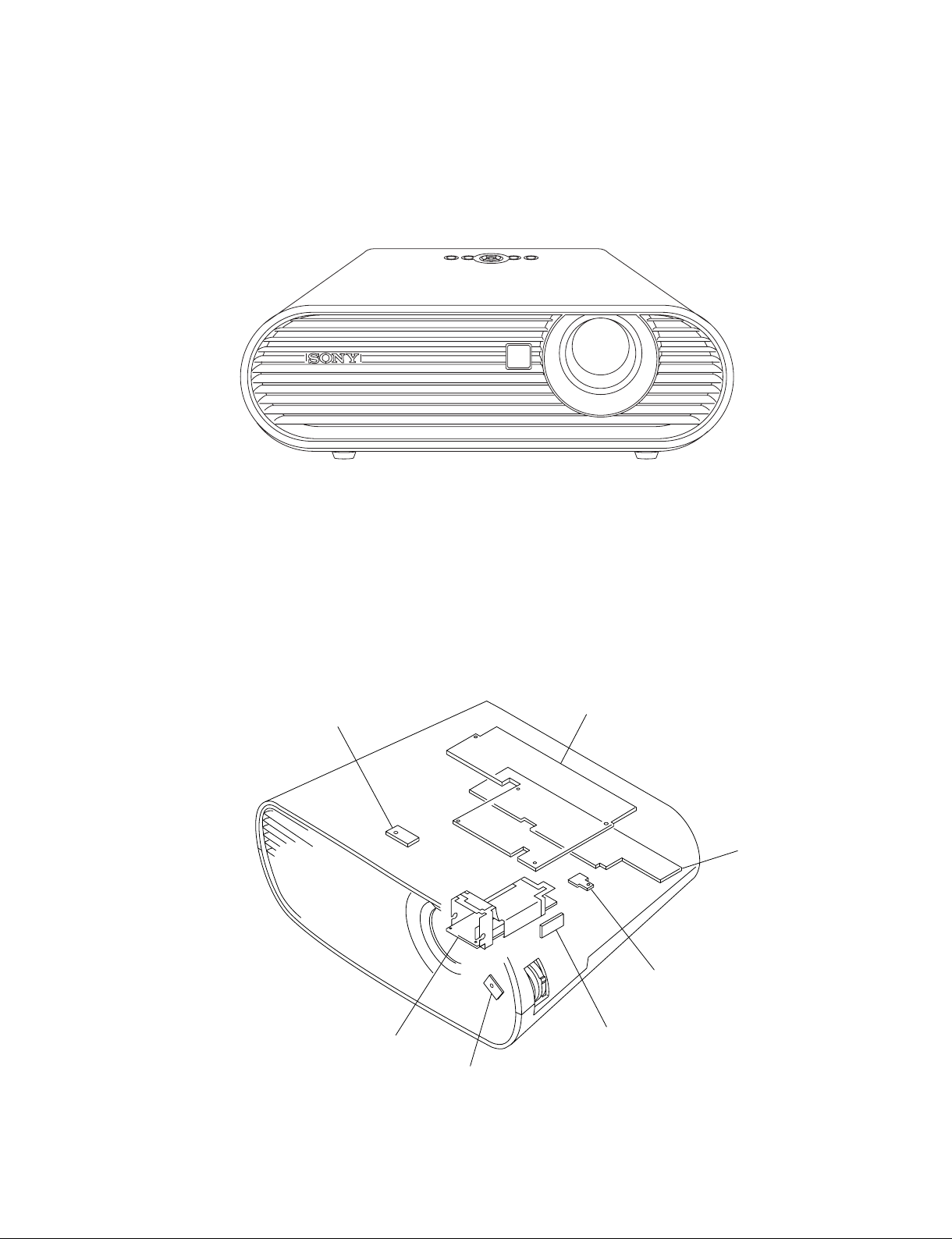
1-1. Appearance Figure
Section 1
Service Overview
1-2. Board Locations
Door detection switch
Lamp power supply
Main
Power
Thermal sensor
Door detection switch
IR sensor
VPL-ES5/EX5/EX50/EX5U/EW5
1-1
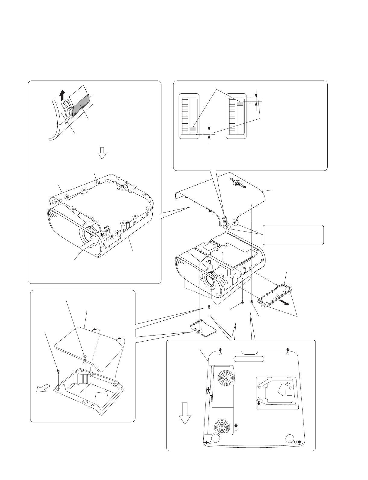
1-3. Disassembly
1-3-1. Upper Case Assembly
Focus adjust gear knob
8
Press here strongly.
9
Remove the Upper case assembly
in the direction of the arrow.
0
Disengage the claws at
the 17 locations respectively.
Upper case assembly
Caution :
Remove the upper case assembly from this corner.
When attaching the upper case assembly, attach it while
aligning with the lower case assembly starting from this corner.
Lower case assembly
Upon completion of the upper
case assembly attachment,
check to see that the spacing
in the top is equal to the
Caution :
If the spacings in the top and bottom are not equal, go to
method of optical unit assembly and Focus/Zoom
(Refer to section 1-3-8. Steps 9 to 14.)
spacing in the bottom.
adjust assembly”.
!- Upper case assembly
These portions are fragile.
Be very careful not to
damage them.
6
Remove the filter
door in the direction
of the arrow
“Assembling
C
.
2 Loosen screw.
4
Screw
(+P M3 x 6)
B
Front Side
of Unit
1-2
3
Lamp door assembly
B
Lower case assembly
B
Front Side
of Unit
A
Screw
A
B
1
Five screws
(+P M3 x 6)
B
7
(+P M3 x 6)
AA
C
5
Two claws
A
VPL-ES5/EX5/EX50/EX5U/EW5
A
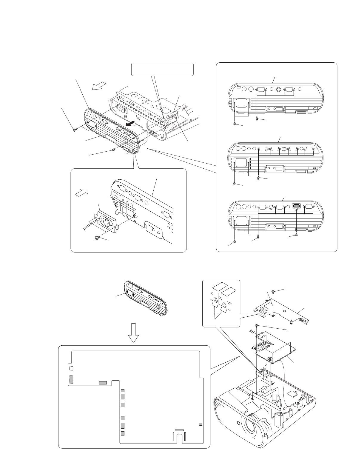
1-3-2. Sub Rear Case Assembly
4
Sub rear case assembly, etc.
3
Two screws
(+K 3 x 12)
VPL-EX5
VPL-EX5U
2
Six hexagon
screws
Rear Side
of Unit
6
Speaker
Rear Side
of Unit
Route the speaker harness
under the MB bracket.
7
Sub rear case assembly
5
Two screws
(+PWH 3 x 6)
Main board
J11
1
Speaker harness
Sub rear case assembly
4
VPL-ES5
3
VPL-EX50
3
VPL-EW5
3
Two screws (+K 3 x 12)
Sub rear case assembly
2
Two screws (+K 3 x 12)
4
Sub rear case assembly
2
Two screws (+K 3 x 12)
4
Sub rear case assembly
2
Six hexagon screws
Four hexagon screws
Eight hexagon screws
8
One screw (+F 3 x 8)
1-3-3. Main Board
1 Sub rear case assembly,
etc.
(Refer to section 1-3-2, steps 1 to 4.)
J11
J17
2
Remove the
twelve connectors.
J16
J26
J21
J20
J14
J19
J18
Main board
J24 J22
J23
J6
Shield
4
Two screws
(+PWH 3 x 6)
5
Shield
3
Three screws
(+PWH 3 x 6)
6
Main board
VPL-ES5/EX5/EX50/EX5U/EW5
1-3
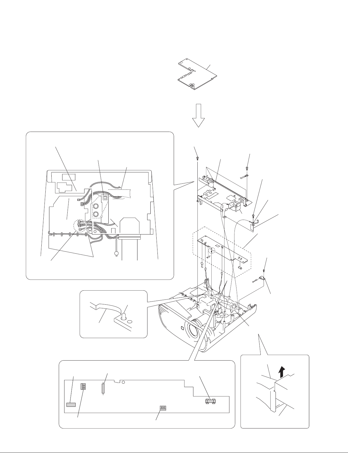
1-3-4. Power Board and Thermal Sensor Board
(Refer to section 1-3-3, steps 2 to 6.)
Check to see that the seven connectors are
protruding from the MB bracket.
Be careful that the harnesses must not override on
top of this port or must not be pinched by this portion.
Duct lamp assembly
1 Mai
6
Four tapping screws
(PAN 3 x 7)
8
n board
MB bracket
5
Screw
(+PSW M4 x 6)
2
Tapping screw
(PAN 3 x 7)
3
Clamp
Caution :
When attaching the MB bracket, bind the five harnesses into the shape
“U”
and attaching them to the MB bracket.
of
0
Dowel
Power board
CN701
Miniature fuse-links (F602)
Fuse (H.B.C.)
(F601)
Fan
!- Power board
Tapping screw
!=
(PAN 3 x 7)
J1
Thermal sensor board
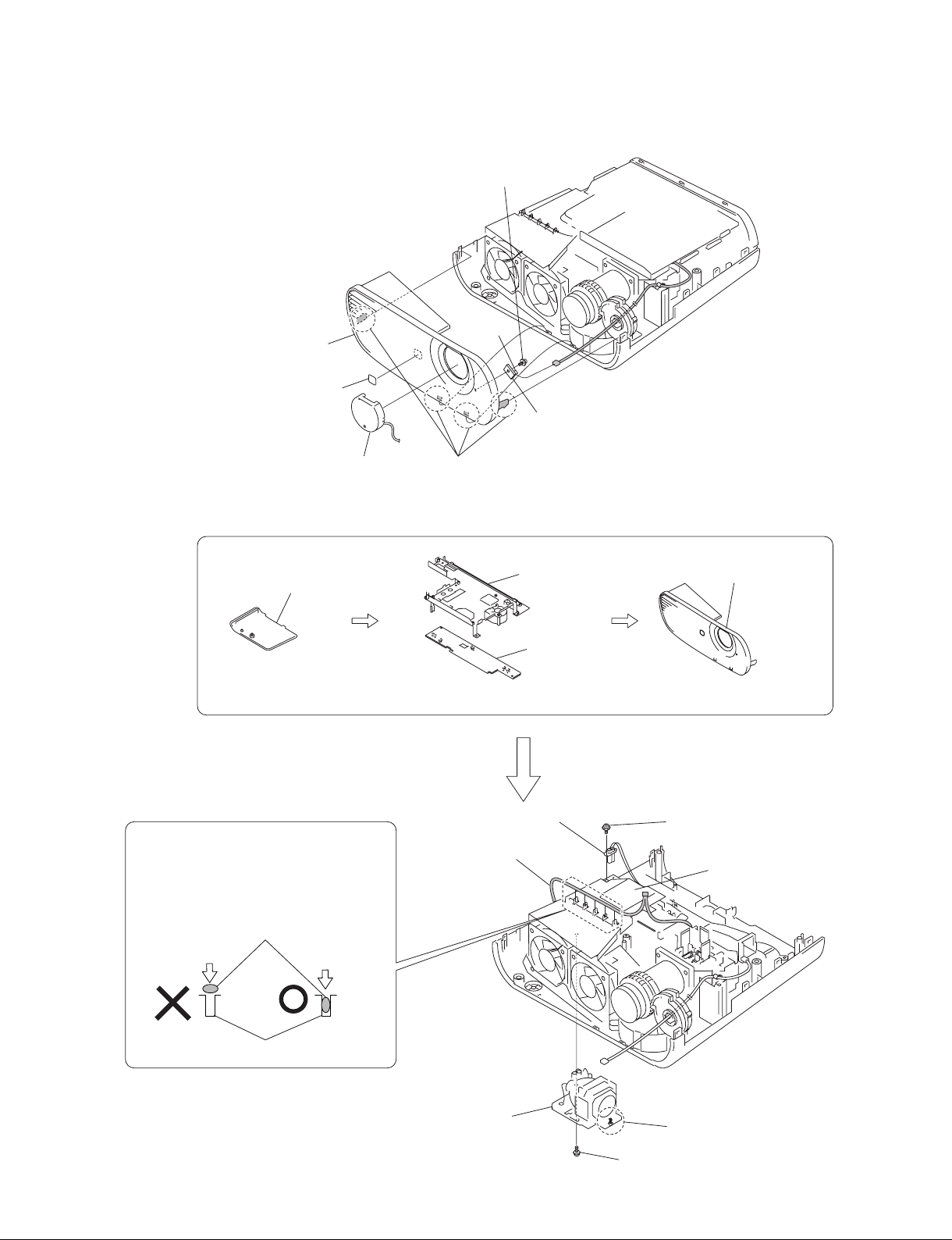
1-3-5. Front Case Assembly and IR Sensor Board
5
Tapping screw
(M3 x 7)
J7
4
Front case assembly
3
Logo
1
Lens cap
2
Four claws
1-3-6. Fan (Exhaust) -1
1
Lamp door assembly
6
IR sensor board
2
MB bracket
4 Front
case assembly
(Refer to section 1-3-1, steps 2 to 4.)
Caution :
Because the harness has the shape of flat
cross-section, do not insert the harness into the
harness clamp section with excessive force.
Find out the direction in which the harness can
be inserted easily, and then insert the harness.
Harness
Harness clamp section
3
Power board
(Refer to section 1-3-4, steps 2 to 11.)
9
Lamp power supply
connector
0
Door detection switch
harness
(Refer to section 1-3-5, steps 1 to 3.)
8
Screw
(+PWH M3 x 6)
Lamp box assembly
VPL-ES5/EX5/EX50/EX5U/EW5
7
Lamp assembly
6 Loosen screw.
5
Screw (+P M3 x 6)
1-5
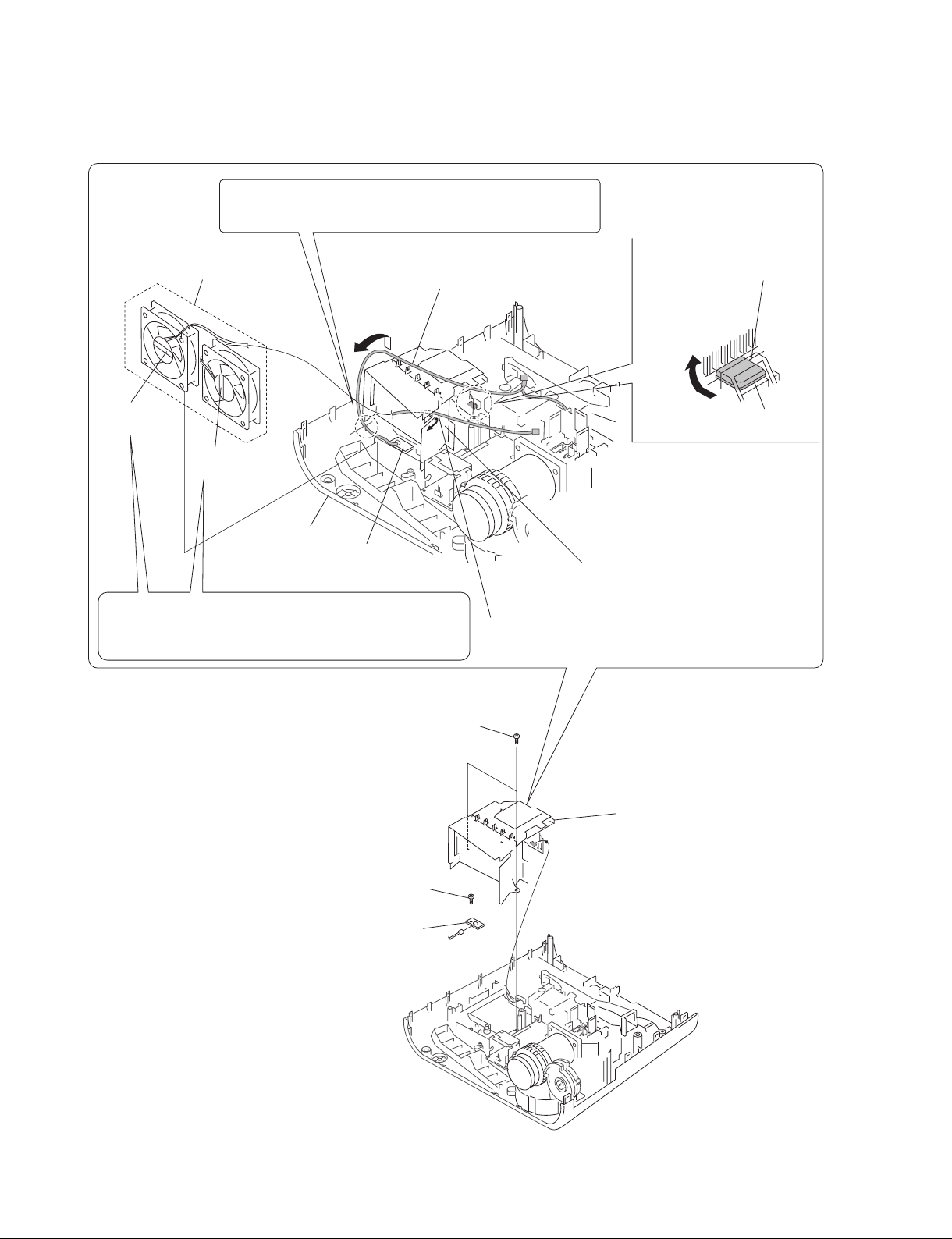
1-3-7. Fan (Exhaust) -2
Caution :
When attaching the lamp box assembly, insert the door detection
switch harness into the groove of the lower case assembly.
3
Fan (Exhaust)
*2 80*25 170MM AD0812UB/HB
4
Remove the door detection switch
harness in the direction of the arrow
5
Remove the protrusion in the
direction of the arrow
C
.
A
.
C
UB mark is
indicated.
HB mark is
indicated.
Lower case assembly
Door detection
switch board
Caution :
Two exhaust fans are the two different fans having the difference
characteristics. Be careful not to make mistake in choosing the
desired fan by confirming the indication on the fans.
1
Two tapping screws
(PAN 3 x 7)
B
A
protrusion
Lamp box assembly
2
Remove the fan harness in the direction of the arrow B.
1-6
7
Tapping screw
(PAN 3 x 7)
8
Door detection switch board
CN1
6
Lamp box assembly
VPL-ES5/EX5/EX50/EX5U/EW5
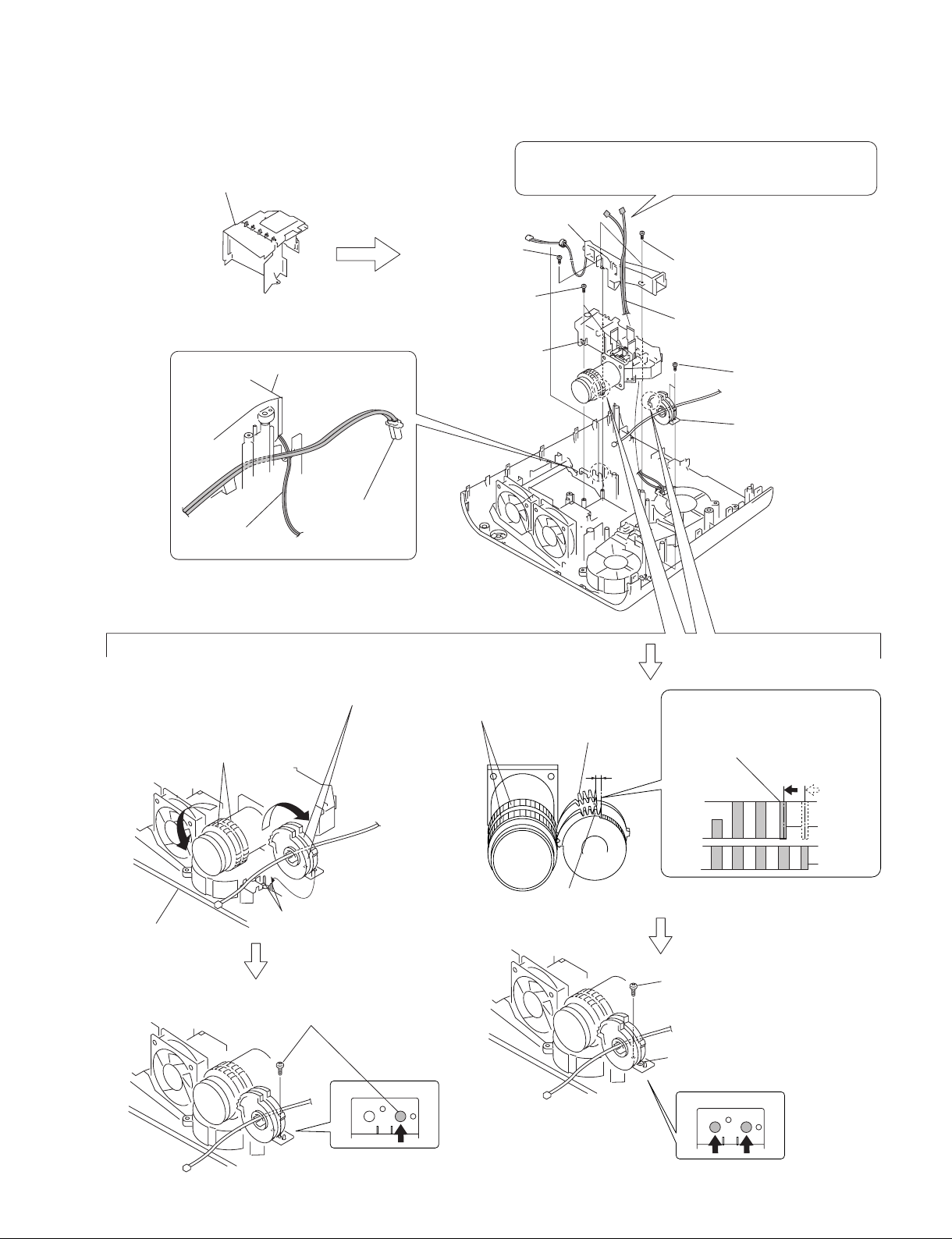
1-3-8. Optical Unit Assembly
1
Lamp box assembly
(Refer to section 1-3-6, steps 5 to 10) and
(refer to section 1-3-7, steps 1,2, 4 to 6.)
Duct lamp assembly
Lamp power supply
CON thermal
145MM wire
connector
4
Duct lamp assembly
3
Tapping screw
(PAN 3 x 10)
7
Three tapping screws
(PAN 3 x 7)
8
Optical unit
assembly
Caution :
When attaching the dust lamp assembly, route that harnesses
in between the duct lamp assembly and optical unit assembly.
2
Two tapping screws
(PAN 3 x 7)
Thermal sensor harness,
Fan harness
5
Two tapping screws
(PAN 3 x 7)
6
Focus/Zoom adjust
assembly
Assembling method of optical unit assembly and
Focus/Zoom adjust gears assembly
0
Attach the Focus/Zoom Adjust assembly into the two
dowels of the lower case assembly after rotating the
Focus/Zoom Adjust assembly as far as it can be rotated
in the direction of clockwise direction.
9
Lens: Rotate the Focus/Zoom gears in
the counter-clockwise direction as far
as it can be rotated.
Lower case assembly
!- Fix the Focus/Zoom Adjust assembly
tentatively with the screw.
Two dowels
Lens: Focus/Zoom gears
Focus adjust gear
Zoom adjust gear
!= Rotate the focus adjust gear in the
counter-clockwise direction by one
tooth. Then, engage these gears
with the corresponding lens gears.
![ Attach the other screw while fixing
the gear position.
VPL-ES5/EX5/EX50/EX5U/EW5
!] Tighten the screw finally that has
been tightened tentatively.
1-7
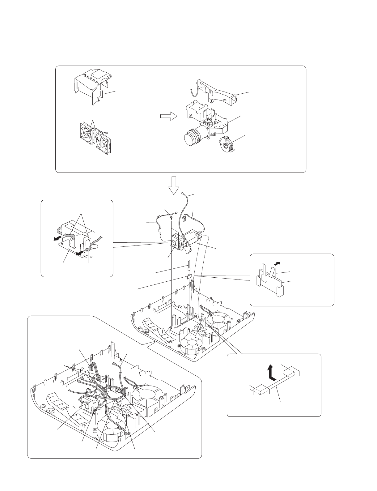
1-3-9. Lamp Power Supply
2
Fan (Exhaust)
*2 80*25 170MM AD0812UB/HB
1
Lamp box assembly
3
Duct lamp assembly
5
Optical unit assembly
4
Focus/Zoom adjust
assembly
(Refer to section 1-3-6, steps 5 to 10) and
(refer to section 1-3-7, steps 1 to 6.)
7
Two
harnesses
Lamp power supply
Door detection
!-
switch board
Caution :
When re-assembling the machine,
route the respective harnesses and
wires at the specified locations as shown.
D
Route the harness D
between them.
6
Two tapping screws
(PAN 3 x 7)
A
C
A
P1
(Refer to section 1-3-8, steps 2 to 8.)
B
D
9
Lamp power supply
CN1
E
0
Claw
Door detection
switch board
Lamp power supply
1-8
B
C
Route the harness
underneath this sheet.
Door detection switch board
A
8
Remove the lamp power supply
in the direction of the arrow
VPL-ES5/EX5/EX50/EX5U/EW5
E
.
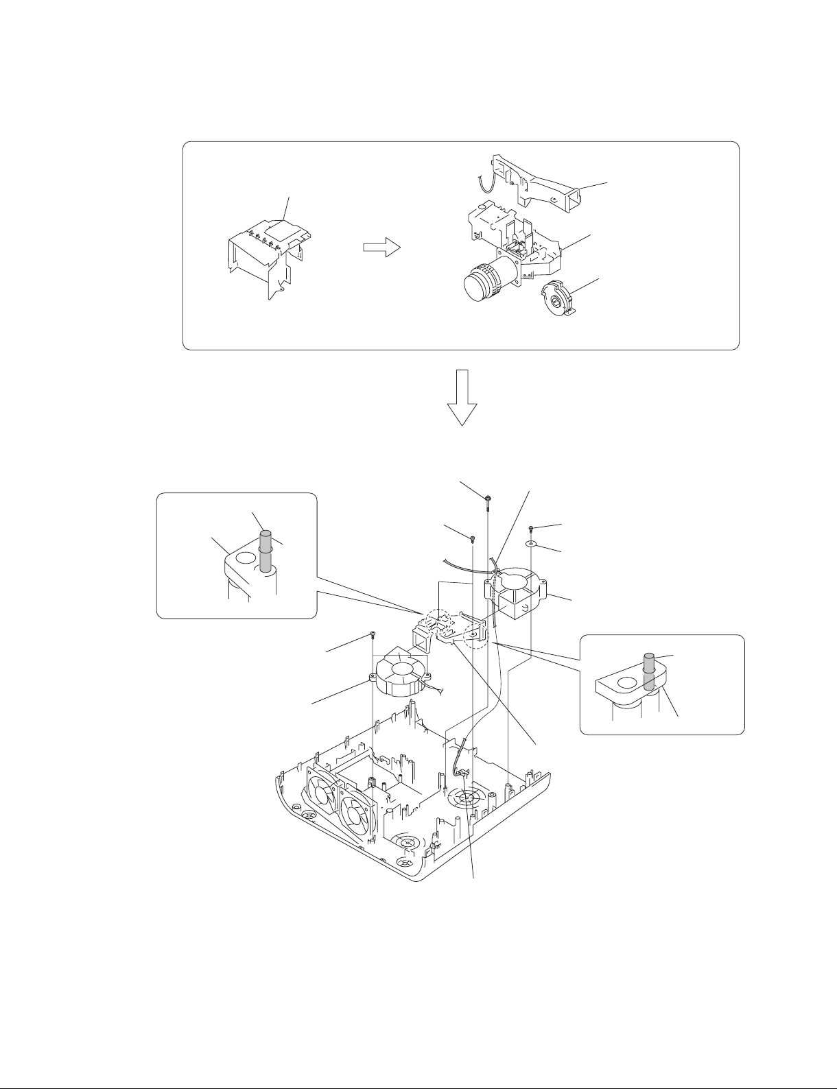
1-3-10. Fan
1
Lamp box assembly
2
Duct lamp assembly
4
Optical unit assembly
3
Focus/Zoom adjust
assembly
(Refer to section 1-3-6, steps 5 to 10) and
(refer to section 1-3-7, steps 1,2, 4 to 6.)
8
Dowel
Prism duct
!] Two tapping screws
(PAN 3 x 10)
!\
Fan
70*70*25 240MM AB07012UB
!= Tapping screw
(PH W/FL M3 x 35NI)
6
Two tapping screws
(PAN 3 x 7)
(Refer to section 1-3-8, steps 2 to 8.)
5
Harness
0
Tapping screw
(PAN 3 x 7)
Washer
!-
1-3-11. 3D GAMMA Service tool Application Software
Feature of 3D Gamma Quick Access :
. It can read 3D gamma data from a set and save it in a file.
. It can write 3D gamma data in a PC into a set.
When the optical unit is replaced, load 3D gamma data recorded on the micro floppy disk, which is
supplied together with the optical unit, into a set using the application software.
File configuration :
Executable : Ernie Service tool.exe
Readme File : readme_j.txt (Japanese)
readme_e.txt (English)
Software Acquisition :
Download the application software from the GSP website.
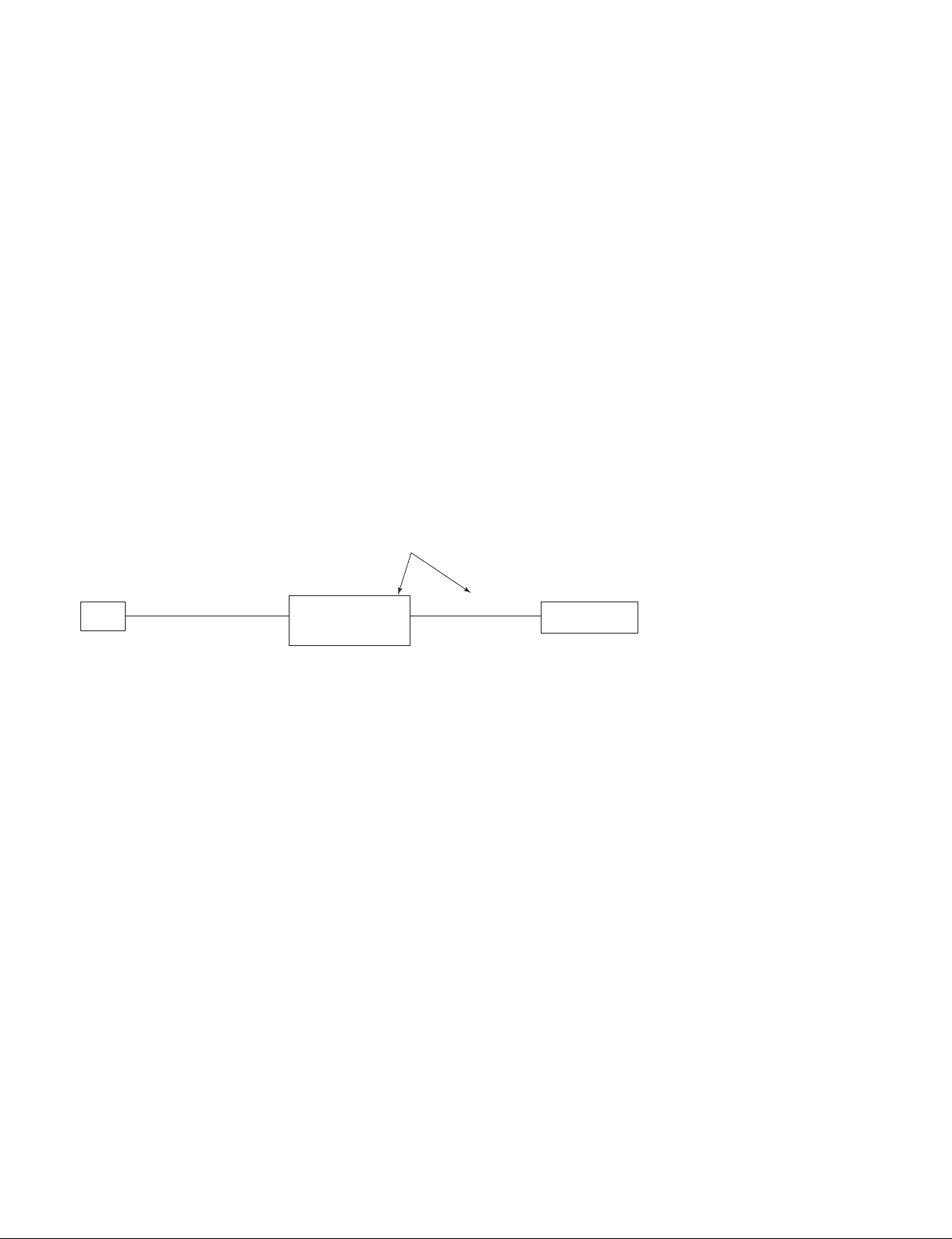
. VPL-ES5 set has not RS-232C terminal, use the PCBA MOTOR TEST BD E08S MI.
. Remove the rubber cap on the upper left of the rear side of the unit.
PCBA MOTOR TEST BD E08S MI
PC
RS-232C
Straight
cable
Dsub
9pin
PCBA MOTOR
TEST BD E08S MI
(Parts No. 9-885-122-51)
CN J8
5pin
CN 5P
J12
Set
Main board CN
1-10
VPL-ES5/EX5/EX50/EX5U/EW5
 Loading...