

Page 1

DATA PROJECTOR
VPLEX100
9
VPL-ES5
VPL-EX5
VPL-EX50
VPL-EX5U
VPL-EW5
REMOTE COMMANDER
RM-PJ4
SERVICE MANUAL
1st Edition (Revised 1)
Page 2

! WARNING
This manual is intended for qualified service personnel only.
To reduce the risk of electric shock, fire or injury, do not perform any servicing other than that
contained in the operating instructions unless you are qualified to do so. Refer all servicing to
qualified service personnel.
! WARNUNG
Die Anleitung ist nur für qualifiziertes Fachpersonal bestimmt.
Alle Wartungsarbeiten dürfen nur von qualifiziertem Fachpersonal ausgeführt werden. Um die
Gefahr eines elektrischen Schlages, Feuergefahr und Verletzungen zu vermeiden, sind bei
Wartungsarbeiten strikt die Angaben in der Anleitung zu befolgen. Andere als die angegeben
Wartungsarbeiten dürfen nur von Personen ausgeführt werden, die eine spezielle Befähigung
dazu besitzen.
! AVERTISSEMENT
Ce manual est destiné uniquement aux personnes compétentes en charge de l’entretien. Afin
de réduire les risques de décharge électrique, d’incendie ou de blessure n’effectuer que les
réparations indiquées dans le mode d’emploi à moins d’être qualifié pour en effectuer d’autres.
Pour toute réparation faire appel à une personne compétente uniquement.
CAUTION
RISK OF EXPLOSION IF BATTERY IS REPLACED BY INCORRECT TYPE.
DISPOSE OF USED BATTERIES ACCORDING TO THE RULE IN REGION.
VPL-ES5/EX5/EX50/EX5U/EW5
Page 3

Table of Contents
1. Service Overview
1-1. Appearance Figure ..........................................................1-1
1-2. Board Locations ..............................................................1-1
1-3. Disassembly ....................................................................1-2
1-3-1. Upper Case Assembly ........................................... 1-2
1-3-2. Sub Rear Case Assembly ......................................1-3
1-3-3. Main Board ............................................................ 1-3
1-3-4. Power Board and Thermal Sensor Board ..............1-4
1-3-5. Front Case Assembly and IR Sensor Board ..........1-5
1-3-6. Fan (Exhaust) -1 ....................................................1-5
1-3-7. Fan (Exhaust) -2 ....................................................1-6
1-3-8. Optical Unit Assembly ..........................................1-7
1-3-9. Lamp Power Supply ..............................................1-8
1-3-10. Fan .........................................................................1-9
1-3-11. 3D GAMMA Service tool Application
Software .............................................................. 1-10
2. Electrical Adjustments
2-1. Initial Values of Adjustment Items .................................2-1
2-2. Memory Structure ...........................................................2-7
3. Troubleshooting
4. Spare Parts
4-1. Notes on Repair Parts ..................................................... 4-1
4-2. Exploded Views .............................................................. 4-2
4-3. Electrical Parts List ......................................................... 4-4
4-4. Packing Materials & Supplied Accessories ....................4-4
4-5. Optional Fixtures ............................................................ 4-4
5. Block Diagrams
Overall (VPL-ES5) ......................................................... 5-1
Overall (VPL-EX50) ...................................................... 5-2
Overall (VPL-EX5) ........................................................ 5-3
Overall (VPL-EX5U) ...................................................... 5-4
Overall (VPL-EW5) ........................................................ 5-5
6. Diagrams
6-1. Frame Schematic Diagrams ............................................6-1
Frame (VPL-ES5) ...........................................................6-1
Frame (VPL-EX50) ........................................................ 6-2
Frame (VPL-EX5/EX5U) ...............................................6-3
Frame (VPL-EW5) ......................................................... 6-4
3-1. Electric Troubleshooting ................................................ 3-1
3-2. Power Board Troubleshooting ........................................3-3
3-2-1. No Power ...............................................................3-3
3-2-2. Failure of Turn on Lamp ....................................... 3-4
3-3. Optical Troubleshooting ................................................. 3-6
VPL-ES5/EX5/EX50/EX5U/EW5
1
Page 4

Page 5

1-1. Appearance Figure
Section 1
Service Overview
1-2. Board Locations
Door detection switch
Lamp power supply
Main
Power
Thermal sensor
Door detection switch
IR sensor
VPL-ES5/EX5/EX50/EX5U/EW5
1-1
Page 6

1-3. Disassembly
1-3-1. Upper Case Assembly
Focus adjust gear knob
8
Press here strongly.
9
Remove the Upper case assembly
in the direction of the arrow.
0
Disengage the claws at
the 17 locations respectively.
Upper case assembly
Caution :
Remove the upper case assembly from this corner.
When attaching the upper case assembly, attach it while
aligning with the lower case assembly starting from this corner.
Lower case assembly
Upon completion of the upper
case assembly attachment,
check to see that the spacing
in the top is equal to the
Caution :
If the spacings in the top and bottom are not equal, go to
method of optical unit assembly and Focus/Zoom
(Refer to section 1-3-8. Steps 9 to 14.)
spacing in the bottom.
adjust assembly”.
!- Upper case assembly
These portions are fragile.
Be very careful not to
damage them.
6
Remove the filter
door in the direction
of the arrow
“Assembling
C
.
2 Loosen screw.
4
Screw
(+P M3 x 6)
B
Front Side
of Unit
1-2
3
Lamp door assembly
B
Lower case assembly
B
Front Side
of Unit
A
Screw
A
B
1
Five screws
(+P M3 x 6)
B
7
(+P M3 x 6)
AA
C
5
Two claws
A
VPL-ES5/EX5/EX50/EX5U/EW5
A
Page 7

1-3-2. Sub Rear Case Assembly
4
Sub rear case assembly, etc.
3
Two screws
(+K 3 x 12)
VPL-EX5
VPL-EX5U
2
Six hexagon
screws
Rear Side
of Unit
6
Speaker
Rear Side
of Unit
Route the speaker harness
under the MB bracket.
7
Sub rear case assembly
5
Two screws
(+PWH 3 x 6)
Main board
J11
1
Speaker harness
Sub rear case assembly
4
VPL-ES5
3
VPL-EX50
3
VPL-EW5
3
Two screws (+K 3 x 12)
Sub rear case assembly
2
Two screws (+K 3 x 12)
4
Sub rear case assembly
2
Two screws (+K 3 x 12)
4
Sub rear case assembly
2
Six hexagon screws
Four hexagon screws
Eight hexagon screws
8
One screw (+F 3 x 8)
1-3-3. Main Board
1 Sub rear case assembly,
etc.
(Refer to section 1-3-2, steps 1 to 4.)
J11
J17
2
Remove the
twelve connectors.
J16
J26
J21
J20
J14
J19
J18
Main board
J24 J22
J23
J6
Shield
4
Two screws
(+PWH 3 x 6)
5
Shield
3
Three screws
(+PWH 3 x 6)
6
Main board
VPL-ES5/EX5/EX50/EX5U/EW5
1-3
Page 8
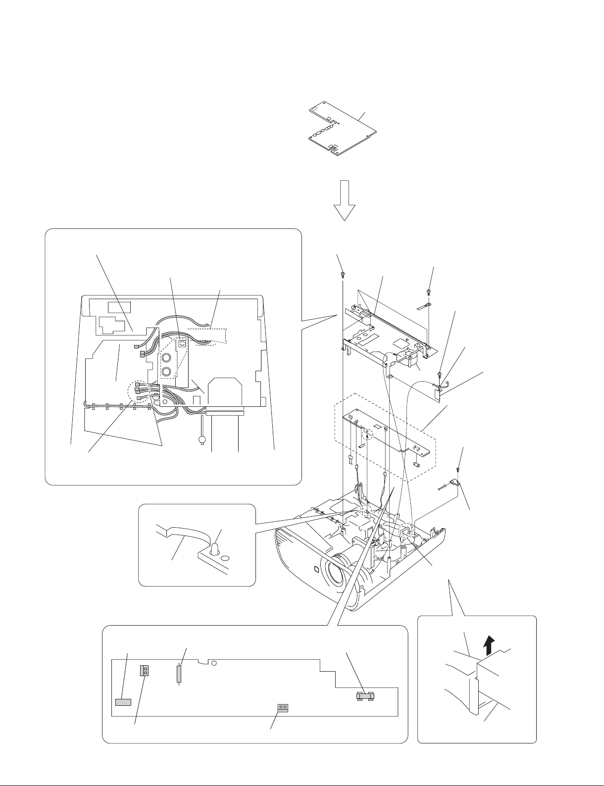
1-3-4. Power Board and Thermal Sensor Board
(Refer to section 1-3-3, steps 2 to 6.)
Check to see that the seven connectors are
protruding from the MB bracket.
Be careful that the harnesses must not override on
top of this port or must not be pinched by this portion.
Duct lamp assembly
1 Mai
6
Four tapping screws
(PAN 3 x 7)
8
n board
MB bracket
5
Screw
(+PSW M4 x 6)
2
Tapping screw
(PAN 3 x 7)
3
Clamp
Caution :
When attaching the MB bracket, bind the five harnesses into the shape
“U”
and attaching them to the MB bracket.
of
0
Dowel
Power board
CN701
Miniature fuse-links (F602)
Fuse (H.B.C.)
(F601)
Fan
!- Power board
Tapping screw
!=
(PAN 3 x 7)
J1
Thermal sensor board
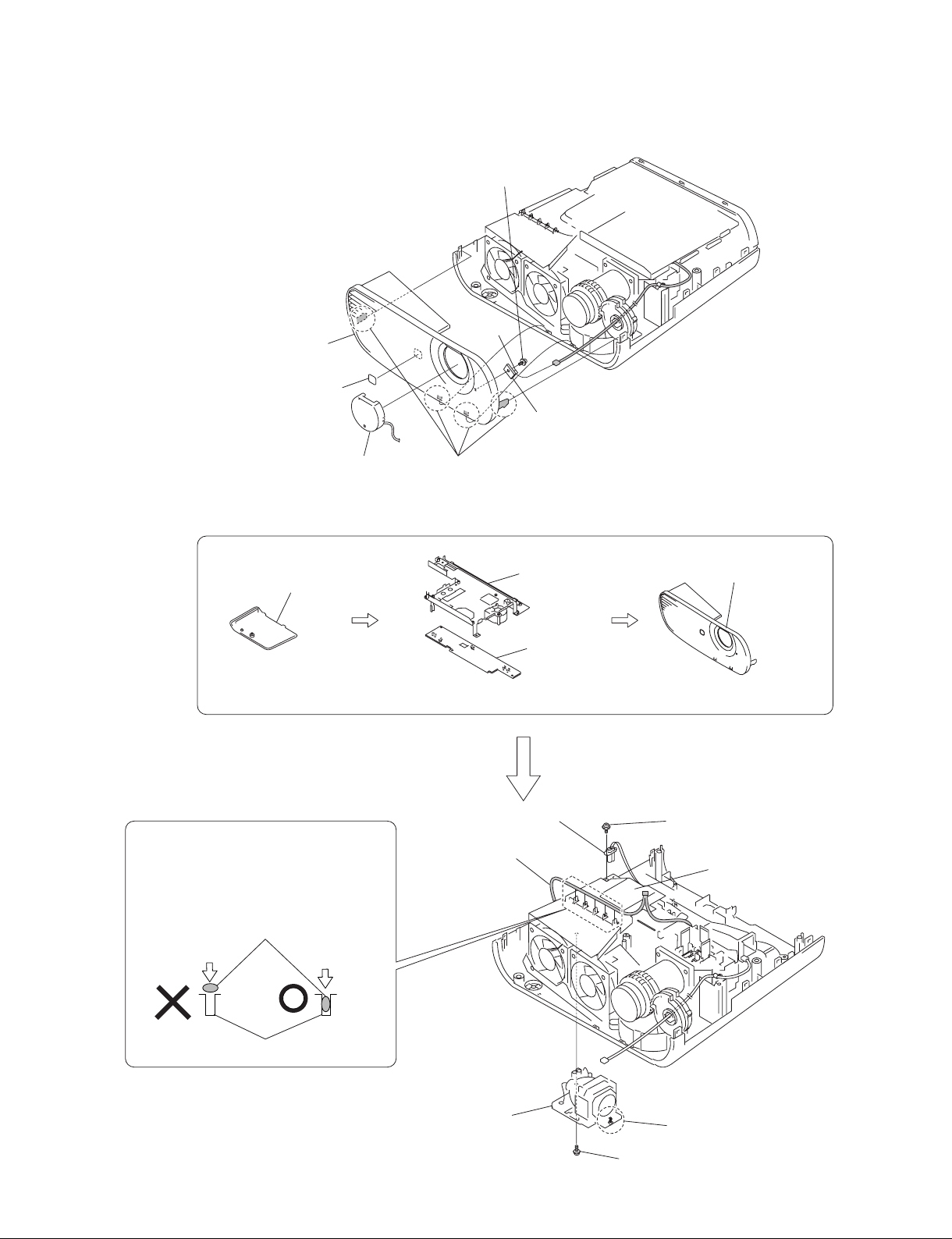
1-3-5. Front Case Assembly and IR Sensor Board
5
Tapping screw
(M3 x 7)
J7
4
Front case assembly
3
Logo
1
Lens cap
2
Four claws
1-3-6. Fan (Exhaust) -1
1
Lamp door assembly
6
IR sensor board
2
MB bracket
4 Front
case assembly
(Refer to section 1-3-1, steps 2 to 4.)
Caution :
Because the harness has the shape of flat
cross-section, do not insert the harness into the
harness clamp section with excessive force.
Find out the direction in which the harness can
be inserted easily, and then insert the harness.
Harness
Harness clamp section
3
Power board
(Refer to section 1-3-4, steps 2 to 11.)
9
Lamp power supply
connector
0
Door detection switch
harness
(Refer to section 1-3-5, steps 1 to 3.)
8
Screw
(+PWH M3 x 6)
Lamp box assembly
VPL-ES5/EX5/EX50/EX5U/EW5
7
Lamp assembly
6 Loosen screw.
5
Screw (+P M3 x 6)
1-5
Page 10

1-3-7. Fan (Exhaust) -2
Caution :
When attaching the lamp box assembly, insert the door detection
switch harness into the groove of the lower case assembly.
3
Fan (Exhaust)
*2 80*25 170MM AD0812UB/HB
4
Remove the door detection switch
harness in the direction of the arrow
5
Remove the protrusion in the
direction of the arrow
C
.
A
.
C
UB mark is
indicated.
HB mark is
indicated.
Lower case assembly
Door detection
switch board
Caution :
Two exhaust fans are the two different fans having the difference
characteristics. Be careful not to make mistake in choosing the
desired fan by confirming the indication on the fans.
1
Two tapping screws
(PAN 3 x 7)
B
A
protrusion
Lamp box assembly
2
Remove the fan harness in the direction of the arrow B.
1-6
7
Tapping screw
(PAN 3 x 7)
8
Door detection switch board
CN1
6
Lamp box assembly
VPL-ES5/EX5/EX50/EX5U/EW5
Page 11

1-3-8. Optical Unit Assembly
1
Lamp box assembly
(Refer to section 1-3-6, steps 5 to 10) and
(refer to section 1-3-7, steps 1,2, 4 to 6.)
Duct lamp assembly
Lamp power supply
CON thermal
145MM wire
connector
4
Duct lamp assembly
3
Tapping screw
(PAN 3 x 10)
7
Three tapping screws
(PAN 3 x 7)
8
Optical unit
assembly
Caution :
When attaching the dust lamp assembly, route that harnesses
in between the duct lamp assembly and optical unit assembly.
2
Two tapping screws
(PAN 3 x 7)
Thermal sensor harness,
Fan harness
5
Two tapping screws
(PAN 3 x 7)
6
Focus/Zoom adjust
assembly
Assembling method of optical unit assembly and
Focus/Zoom adjust gears assembly
0
Attach the Focus/Zoom Adjust assembly into the two
dowels of the lower case assembly after rotating the
Focus/Zoom Adjust assembly as far as it can be rotated
in the direction of clockwise direction.
9
Lens: Rotate the Focus/Zoom gears in
the counter-clockwise direction as far
as it can be rotated.
Lower case assembly
!- Fix the Focus/Zoom Adjust assembly
tentatively with the screw.
Two dowels
Lens: Focus/Zoom gears
Focus adjust gear
Zoom adjust gear
!= Rotate the focus adjust gear in the
counter-clockwise direction by one
tooth. Then, engage these gears
with the corresponding lens gears.
![ Attach the other screw while fixing
the gear position.
VPL-ES5/EX5/EX50/EX5U/EW5
!] Tighten the screw finally that has
been tightened tentatively.
1-7
Page 12

1-3-9. Lamp Power Supply
2
Fan (Exhaust)
*2 80*25 170MM AD0812UB/HB
1
Lamp box assembly
3
Duct lamp assembly
5
Optical unit assembly
4
Focus/Zoom adjust
assembly
(Refer to section 1-3-6, steps 5 to 10) and
(refer to section 1-3-7, steps 1 to 6.)
7
Two
harnesses
Lamp power supply
Door detection
!-
switch board
Caution :
When re-assembling the machine,
route the respective harnesses and
wires at the specified locations as shown.
D
Route the harness D
between them.
6
Two tapping screws
(PAN 3 x 7)
A
C
A
P1
(Refer to section 1-3-8, steps 2 to 8.)
B
D
9
Lamp power supply
CN1
E
0
Claw
Door detection
switch board
Lamp power supply
1-8
B
C
Route the harness
underneath this sheet.
Door detection switch board
A
8
Remove the lamp power supply
in the direction of the arrow
VPL-ES5/EX5/EX50/EX5U/EW5
E
.
Page 13

1-3-10. Fan
1
Lamp box assembly
2
Duct lamp assembly
4
Optical unit assembly
3
Focus/Zoom adjust
assembly
(Refer to section 1-3-6, steps 5 to 10) and
(refer to section 1-3-7, steps 1,2, 4 to 6.)
8
Dowel
Prism duct
!] Two tapping screws
(PAN 3 x 10)
!\
Fan
70*70*25 240MM AB07012UB
!= Tapping screw
(PH W/FL M3 x 35NI)
6
Two tapping screws
(PAN 3 x 7)
(Refer to section 1-3-8, steps 2 to 8.)
5
Harness
0
Tapping screw
(PAN 3 x 7)
Washer
!-
1-3-11. 3D GAMMA Service tool Application Software
Feature of 3D Gamma Quick Access :
. It can read 3D gamma data from a set and save it in a file.
. It can write 3D gamma data in a PC into a set.
When the optical unit is replaced, load 3D gamma data recorded on the micro floppy disk, which is
supplied together with the optical unit, into a set using the application software.
File configuration :
Executable : Ernie Service tool.exe
Readme File : readme_j.txt (Japanese)
readme_e.txt (English)
Software Acquisition :
Download the application software from the GSP website.
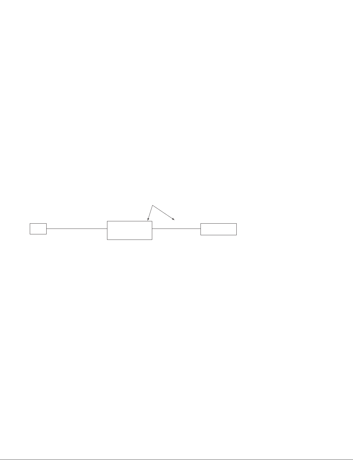
. VPL-ES5 set has not RS-232C terminal, use the PCBA MOTOR TEST BD E08S MI.
. Remove the rubber cap on the upper left of the rear side of the unit.
PCBA MOTOR TEST BD E08S MI
PC
RS-232C
Straight
cable
Dsub
9pin
PCBA MOTOR
TEST BD E08S MI
(Parts No. 9-885-122-51)
CN J8
5pin
CN 5P
J12
Set
Main board CN
1-10
VPL-ES5/EX5/EX50/EX5U/EW5
Page 15

Set
Dynamic Standard Game Living Cinema Dynamic Standard Game Living Cinema Dynamic Standard Game Living Cinema
Present-
ation
Present-
ation
Present-
ation
Present-
ation
Dynamic Standard Game Living Cinema
Picture Mode
Adjust Picture
Contrast
90 80 90 90 75 85 90 80 90 90 75 75 90 80 90 90 75 85 90 80 90 90 60 85
Bright
60 50 60 50 50 55 60 50 60 50 50 55 60 50 60 50 50 55 60 50 60 50 50 55
Color
50 50 68 60 58 50 50 50 68 60 58 50 50 50 68 60 58 50
Hue
50 50 50 50 50 50 50 50 50 50 50 50
Sharpness
60 30 50 50 30 50 60 30 40 40 30 40 60 30 40 40 30 40
DDE
Film Film Film Film Film Film Film Film Film Film Film Film Film Film Film Film Film Film
Gamma Mode
Graphics Graphics Graphics Graphics Graphics Graphics
Color Temp
High Low High Low Low High High Low High Low Low High High Low High Low Low High High Low High Low Low
Volume
30
Adjust Signal
Dot Phase 31
H Size
Shift
Aspect refer to Aspect Default
Smart APA On
Auto Input Search Off
Input-A Signal Sel. Auto
Color System Auto
Power Saving Mode Off
IR Receiver Front & Rear
Panel Key Lock Off
Lamp Timer Reset
Status On
Language English
Menu Position Center
Start Up Image On
Auto Keystone *1
V Keystone *2
Auto
Keystone *10
0
Image Flip Off
Background Blue
Lamp Mode *1 Standard
High Altitude Mode
*1
Off
Security Lock Off
Key Enter x 4
Direct Power On Off
VIDEO
INPUT A (Component/VideoGBR) INPUT A (Computer), INPUT B (Computer)
PICTURE
SETTING
S VIDEO
INPUT
SETTING
SET
SETTING
MENU
SETTING
INSTALL
SETTING
*3
*3
*3
*3
INFORMATION
All information is
display only
Section 2
Electrical Adjustments
MORY No.).
2-1. Initial Values of Adjustment Items
VPL-ES5/EX5/EX50/EX5U/EW5
*1: VPL-EX5/EX50/EX5U/EW5 only
*2: VPL-ES5 only
*3: The “Picture Mode” items in the “PICTURE SETTING” menu have their respective initial values for each input signal (PRESET ME
n
There are some adjustment items that cannot be adjusted, depending on the input signal.
2-1
Page 16

SVGA(ES5) / XGA(EX5/EX50/EX5U) / WXGA(EW5)
No. Preset Signal
1 VIDEO/60 60Hz
2 VIDEO/50 50Hz
3 480/60i 480/60i
4 575/50i 575/50i
480/60p (progressive
5 480/60p
component)
575/50p (progressive
6 575/50p
component)
7 1080/60i 1035/60i, 1080/60i
8 1080/50i 1080/50i
10 720/60p 720/60p
11 720/50p 720/50p
21 *
640x350
VGA mode1
22 * VGA VESA 85Hz
23 *
640x400
NEC PC98
24 * VGA mode 2
PC Component Video GBR
*1
-
-
-
-
-
-
-
-
Full1
-
4:3 / Normal
4:3 / Normal
4:3 / Normal
4:3 / Normal
4:3 / Normal *14:3 / Normal
4:3 / Normal *14:3 / Normal
16:9 / Full
16:9 / Full
16:9 / Full
16:9 / Full
4:3 / Normal
*1
4:3 / Normal
*1
4:3 / Normal
*1
4:3 / Normal
*2
16:9 / Full
*2
16:9 / Full
*2
16:9 / Full
*2
16:9 / Full
Full1 - -
Full1 - 25 * VGA VESA 85Hz
26 *
640x480
VGA mode 3
27 * Macintosh 13"
28 * VGA VESA 72Hz
Full1
4:3 / Normal *14:3 / Normal
29 * VGA VESA 75Hz (IBM M3)
30 * VGA VESA 85Hz
31 *
800x600
SVGA VESA 56Hz
32 * SVGA VESA 60Hz
33 * SVGA VESA 72Hz
Full1 - 34 * SVGA VESA 75Hz
35 * SVGA VESA 85Hz
36 * 832x624 Macintosh 16"
37 *
1024x768
XGA VESA 60Hz
38 * XGA VESA 70Hz
39 * XGA VESA 75Hz
Full1
Full1 - -
--
40 * XGA VESA 85Hz
41 *
1152x864
42 SXGA VESA 75Hz
SXGA VESA 70Hz
Full1 - 43 SXGA VESA 85Hz
44 *
45 *
1152x900
1280x960
46 SXGA VESA 75Hz
47 *
1280x1024
48 SXGA VESA 75Hz
*
49 SXGA VESA 85Hz
50
1400x1050
55 1280x768 WXGA 60Hz
56 1280x720p WXGA 60Hz Full1
SUN LO
SXGA VESA 60Hz
SXGA VESA 60Hz
SXGA+ 60Hz
Full1
--
Full1 - -
Full1 - -
Full1
Full1
--
--
16:9 / Full
*2
16:9 / Full
60 1360x768 1360x768/60 Full1 - 61 1440x900 1440x900/60 Full1 - 63 1280x800 1280x800/60 Full1 - -
*1
*1
*1
*1
*1
*1
*2
*2
*2
*2
*1
*2
*1: VPL-EW5 : Normal
*2: VPL-EW5 : Full
2-2
VPL-ES5/EX5/EX50/EX5U/EW5
Page 17

Set
ES5
Page Item Name R G B
EX5/EX50/EX5U
EW5
Color
P1-1
CXD9809
(ES5)
CXD3540
(EX5/EX50/
EX5U/EW5)
page1
P1-2
CXD9809
(ES5)
CXD3540
(EX5/EX50/
EX5U/EW5)
page2
TGHST Phase Hi
TGHST Phase Lo
SHSH1
TGHST Position
DEHPF On
DEHPF AAC
DEHPF TAP
DEUSC On
3D GammaSubCont
3D GammaSubBrt
DELUT SW
DEUF SW
Full Black/White SW
PC Hi Gain-R
PC Hi Gain-G
PC Hi Gain-B
PC Hi Bias-R
PC Hi Bias-G
PC Hi Bias-B
PC Lo Gain-R
PC Lo Gain-G
PC Lo Gain-B
PC Lo Bias-R
PC Lo Bias-G
PC Lo Bias-B
0
109
38
12
ON
ON
3
OFF
0
150
OFF
128
128
128
128
70
100
ON
ON
512
512
512
0
0
0
512
280
400
0
0
0
P1-3
CXD9809
(ES5)
CXD3540
(EX5/EX50/
EX5U/EW5)
page3
VPL-ES5/EX5/EX50/EX5U/EW5
Video Hi Gain-R
Video Hi Gain-G
Video Hi Gain-B
PC Mid Bias-R
Video Hi Bias-G
Video Hi Bias-B
Video Lo Gain-R
Video Lo Gain-G
Video Lo Gain-B
Video Lo Bias-R
Video Lo Bias-G
Video Lo Bias-B
128
80
120
128
70
100
512
320
480
0
0
0
512
280
400
0
0
0
2-3
Page 18

Page Item Name
PC Mid Gain-R
PC Mid Gain-G
P1-4
CXD980
(ES5)
PC Mid Gain-B
PC Mid Bias-R
PC Mid Bias-G
PC Mid Bias-B
CXD3540
(EX5/EX50/
EX5U/EW5)
page4
Video Mid Gain-R
Video Mid Gain-G
Video Mid Gain-B
Video Mid Bias-R
Video Mid Bias-G
Video Mid Bias-B
ES5
128
90
115
128
75
105
Set
EX5/EX50/EX5U
512
360
460
0
0
0
512
300
420
0
0
0
EW5
Color
RGB
P2
Fan Control
P3-1
CXA7006
(ES5)
CXA7009
(EX5/EX50/
EX5U/EW5)
page1
Temperature 1
Temperature 2
Display
only
Display only
Temperature 3 N/A
FanSpeed 1
FanSpeed 2
FanSpeed 3
FanSpeed 4
Display only
Display only
Display only
Display only
ManualFanSpeed OFF
Burn-In Cycle 0
Burn-In Cycle On min.
Burn-In Cycle Off min.
210
30
Burn-In Hour 50
Burn-In active OFF
Gain-R
Gain-G
Gain-B
SigCen-R
SigCen-G
SigCen-B
SidA-R
SidA-G
SidA-B
SidB-R
SidB-G
SidB-B
154
154
154
161
161
161
22
22
22
85
85
85
194
194
194
47
47
47
156
156
156
N/A
211
211
211
48
48
48
18
18
18
152
152
152
2-4
VPL-ES5/EX5/EX50/EX5U/EW5
Page 19

Page Item Name
Bias-R Normal
Bias-G Normal
P3-2
CXA7006
(ES5)
CXA7009
(EX5/EX50/
EX5U/EW5)
page2
Bias-B Normal
Bias-R Flip
Bias-G Flip
Bias-B Flip
Vcom-R Normal
Vcom-G Normal
Vcom-B Normal
Vcom-R Flip
Vcom-G Flip
Vcom-B Flip
RGB Calibrate
YUV Calibrate
RGB Offset 164 222 164
RGB Gain 93 105 93
YUV Offset 164 222 164
P4
ADC Calibration
YUV Gain 93 105 93
R Offset 164
G Offset 222
B Offset 164
R Gain 93
G Gain 105
B Gain 93
ES5
112
112
112
112
112
112
88
88
88
88
88
88
Set
EX5/EX50/EX5U
0
0
0
0
0
0
83
83
83
83
83
83
EW5
99
100
99
99
100
99
R
Color
GB
Power Savin
g Time 10
System Protect ON
Data Reset
Hard Reset *
ROM Version
P5
Lamp Timer
Operation Timer
Prev. Lamp Timer
SOG Threshold 9
P6
All value is display only
Error Count
* : Hard reset deletes the adjusted data and restores the default data.
VPL-ES5/EX5/EX50/EX5U/EW5
Not use
Display only
Display only
Display only
Display only
2-5
Page 20

Page Item Name
average time
Current Y Axis
Current Tout counts
Save T1 data
P7
T1:
Axis1:
Keystone
Adjustment
Save T2 data
T2:
Axis2:
set manual 'b' left key x
a
b
Calculate sensitivity
sensitivity
current g
ES5
Set
EX5/EX50/EX5U
Display
only
Display
only
Display
only
1
1
1
1
1000
1
1
1
Display
only
EW5
2-6
VPL-ES5/EX5/EX50/EX5U/EW5
Page 21

2-2. Memory Structure
Set memory Set memory Set memory
status
memory
Picture
memory
W/B
memory
Aspct memory
Common
Memory
No.01 No.01 Status memory
No.02 No.02
No.03 No.03
No.04 No.04
No.05 No.05
--- --No.50 No.50
No.55 No.55
No.56 No.56
No.60 No.60
No.61 No.61
No.63 No.63
Video
S-Video
Input-A
Input-B
Component
HDMI (video type) *1
HDMI (DVI type) *1
Computer
Other than
Computer
Video, S-Video
Input-A
Input-B
Smart APA
(Computer only)
Volume Volume
Auto Input Search Auto Input Search
Input-A Signal Sel. Input-A Signal Sel.
Color System
(Video/S-Video Only)
Power Saving Power Saving
IR Receiver IR Receiver
Panel Key Lock Panel Key Lock
Status Status
Language Language
Menu Position Menu Position
Start Up Image Start Up Image
Auto Keystone *2 Auto Keystone *2
Keystone Keystone
Image Flip Image Flip
Background Background
Lamp Mode Lamp Mode
High Altitude High Altitude
Security Lock Security Lock
Direct Power On Direct Power On
FLASH ROM EEP ROM
Dynamic Dynamic
Standard Standard
Game Game
Living Living
Cinema Cinema
Presentation Presentation
Dynamic Dynamic
Standard Standard
Game Game
Living Living
Cinema Cinema
Presentation Presentation
Dynamic Dynamic
Standard Standard
Game Game
Living Living
Cinema Cinema
Presentation Presentation
Dynamic Dynamic
Standard Standard
Game Game
Living Living
Cinema Cinema
Presentation Presentation
Dynamic Dynamic
Standard Standard
Game Game
Living Living
Cinema Cinema
Presentation Presentation
Dynamic
Standard
Game
Living
Cinema
Presentation
Dynamic
Standard
Game
Living
Cinema
Presentation
High High
Mid Mid
Low Low
High High
Mid Mid
Low Low
Video/Svideo
status
memory
memory
W/B memory
No.1 No.1 Aspect memory
No.2 No.2
No.03 No.03
No.04 No.04
No.05 No.05
--- --No.50 No.50
No.55 No.55
No.56 No.56
No.60 No.60
No.61 No.61
No.63 No.63
No.21 No.21
No.22 No.22
No.23 No.23
--- --No.50 No.50
No.55 No.55
No.56 No.56
No.60 No.60
No.61 No.61
No.63 No.63
Aspct memory
Common
Memory
picture
Input-A/Input-B
/Component
Video
S-Video
Input-A
Input-B
Component
HDMI (video type) *1
HDMI (DVI type) *1
Computer
Other than
Computer
Video, S-Video
Input-A
Input-B
Smart APA
(Computer only)
Color System
(Video/S-Video Only)
Dynamic
Standard
Game
Living
Cinema
Presentation
Dynamic
Standard
Game
Living
Cinema
Presentation
Picture memory
*1 : VPL-EW5 only
W/B memory
Common Memory
*2 : VPL-EX5/EX50/EX5U/EW5 only
CPU RAM
VPL-ES5/EX5/EX50/EX5U/EW5
2-7
Page 22

Memory structure of this model consists of the followings.
1 Set memory
2 Status memory
3 Picture memory
4 Chroma memory
5 W/B memory
6 Channel memory
* The gamma memory is realized by giving offset to the Contrast and Brightness output values to the
devices in the gamma mode function.
Flow of data is described briefly. When the power plug is connected to the wall outlet for the first time
(Standby state), all data that are stored in the internal ROM are written in the NVM (non-volatile memory). When the POWER is turned ON, all the status memory data and other memory data that are required
for the present picture are selected from each memory block and expanded in the internal RAM.
When any adjustment is performed at this moment, the adjustment data (user mode items) are written in
the NVM (Service/Special Service) automatically triggered by the memory operation.
The adjustment items (W/B, Device Adjust) that can be adjusted in the Service Mode or in the Special
Service Mode, are memorized in the NVM at the time when the user performs adjustment and performs
the memory operation. Note that the factory adjustment data will be lost at this moment.
2-8
VPL-ES5/EX5/EX50/EX5U/EW5
Page 23

3-1. Electric Troubleshooting
Connect the Power
Section 3
Troubleshooting
System Standby?
Ye s
Power projector
Lamp ON ?
Ye s
System shut-down
And cooling
No
No Picture ?
No
No
No
Ye s
Ye s
1. Check the LED Message and find error.
2. Check lamp door, dust door.
3. Check the power board out voltage 5V.
4. Change main board.
1. check the Ballast power and control
signal wire.
2. Check lamp door status.
3. Check lamp status.
1. Check the LED message and find error.
2. Check the Fan status or Thermal sensor
status.
3. Check the lamp door or dust door.
1. The picture is full-white pattern; please
check the LCD panel connector. (only ES5)
2. The picture is full-black pattern; please check
the LCD panel connector. (only EX5/EX50/
EX5U/EW5) please check the LCD driver on
the main board.
3. Check the system status: Is system in
burn-in mode?
Picture quality
No good ?
VPL-ES5/EX5/EX50/EX5U/EW5
No
Ye s
1. The picture a little green, blue, red,
please check the LCD panel connector.
2. The picture has dust, please check the
lens.
3. The picture flicker, please alignment
again.
1
3-1
Page 24

1
OSD flicker ?
No
Color temp wrong ?
No
Picture has
Vertical bar ?
No
IR remote control
No good ?
Yes
Yes
Yes
Yes
Please alignment V-com again.
Please alignment color temperature again.
Check the vertical bar color and find the
LCD panel connector. Then check the pin
of connector.
1. Please check the OSD setting
2. Check the front IR board.
No
Audio function is
No good ?
Yes
1. Check the OSD setting.
2. Check the speak wire.
3-2
VPL-ES5/EX5/EX50/EX5U/EW5
Page 25

3-2. Power Board Troubleshooting
3-2-1. No Power
No Power
Replace Q601 and F601
with new ones, and then
put power board into set.
If Q601 damages again,
check if other parts are
shorted.
Check if 15.25V or 12V
exist. If any voltage is
wrong, replace IC701 or
T602 with new ones.
Yes
Yes
F601
Open?
Yes
Q601 (D-S)
Short ?
No
Output
5V DC
exists ?
No
Voltage
outputs shut
down and built
repeatly ?
No
Yes
Check if CN701 inserted
properly.
Check if miss to solder
any SMD type of
components.
Check if D602 or IC602 is
broken.
if yes,replace it with now
one.
VPL-ES5/EX5/EX50/EX5U/EW5
No
Check LED circuit of
main board.
Check CN701 and find
out if some points are
shorted to gound.
3-3
Page 26

3-2-2. Failure of Turn on Lamp
Failure of turn on ballast.
Check main board.
A
Check if the input
voltage of ballast is
380V DC
No
Lamp
Broken ?
No
No
Control
Pin (SCI) is
normal ?
Yes
Replace ballast with new
one.
Yes
Yes
B
Replace lamp with new
one.
3-4
VPL-ES5/EX5/EX50/EX5U/EW5
Page 27

B
Check mian board.
A
No
exists at c-terminal
Yes
Check if there
is PFC_On/Off
signal.
Yes
Check if 18V
of Q603.
Yes
F602 Open ?
No
Q602 works
normally ?
No
Yes
Check Q701, IC604,
IC605, Q604, Q603,
Q653 or ZD603.
And then replace broken
parts.
Replace F602 with new
one.
VPL-ES5/EX5/EX50/EX5U/EW5
No
Check ZD602, R655 and
R656.
3-5
Page 28

3-3. Optical Troubleshooting
Connect the Power
Brightness
No good ?
No
Flicker ?
No
Color
No good ?
No
No Color Uniformity ?
No
No Focus ?
Yes
Yes
Yes
Yes
Yes
1. Check the EE setting (ADC calibration) /
Follow up EE alignment procedure.
2. Check the Lamp assembly.
1. Check the R,G,B VCOM.
1. Check the R,G,B Gain.
2. Check the Panel cable connector.
1. Check uniformity R,G,B value.
1. Check the Projection lens at datum surface.
3-6
No
Dust ?
No
Black level
No good ?
Yes
Yes
1. Cleaning the Lens array (front of lamp).
2. Cleaning the R,G,B Panel.
1. Check the FPC cable connecting.
VPL-ES5/EX5/EX50/EX5U/EW5
Page 29

4-1. Notes on Repair Parts
1. Safety Related Components Warning
w
Components marked ! are critical to safe operation.
Therefore, specified parts should be used in the case of
replacement.
[WARNHINWEIS][WARNHINWEIS]
[WARNHINWEIS]
[WARNHINWEIS][WARNHINWEIS]
Les composants identifiés par la marque ! sont
critiques pour la sécurité.
Ne les remplacer que par une pièce portant le numéro
spécifié.
2. Standardization of Parts
Some repair parts supplied by Sony differ from those
used for the unit. These are because of parts commonality and improvement.
Parts List has the present standardized repair parts.
Section 4
Spare Parts
3. Stock of Parts
Parts marked with “o” at SP (Supply Code) column of
the Spare Parts list may not be stocked. Therefore, the
delivery date will be delayed.
Items with no part number and no description are not
stocked because they are seldom required for routine
service.
4. Units for Capacitors, Inductors and Resistors
The following units are assumed in Schematic Diagrams, Electrical Parts List and Exploded Views
unless otherwise specified.
Capacitors : μF
Inductors : μH
Resistors : Ω
5. Note for Electrical key
The components identified by mark contain confidential information.
Strictly follow the instructions whenever the components are repaired and/or replaced.
VPL-ES5/EX5/EX50/EX5U/EW5
4-1
Page 30

Overall
4-2. Exploded Views
22
46
11
3
36
12
33
46
16
51
B
37
A
3
31
3
A
3
3
B
44
46
15
3
3
28
14
3
20
3
39
40
13
3
19
47
21
35
52
42
42
VPL-EX5
VPL-EX5U
43
VPL-ES5
43
4-2
41
29
17
26
27
32
45
25
45
34
24
23
38
18
1
2
3
3
35
VPL-EX50
42
35
42
35
VPL-ES5/EX5/EX50/EX5U/EW5
43
VPL-EW5
53
43
Page 31

No. Part No. SP Description
1 ! 1-576-233-51 s FUSE (H.B.C.) (F601)
2 ! 1-576-973-11 s MINIATURE FUSE-LINKS (F602)
3 2-681-550-01 s SCREW, TAP PAN M3*7L
11 9-885-118-05 s WIRE 2P_CON+THERMAL 145MM E08X
12 ! 9-885-118-06 s FAN*2 80*25 170MM AD0812UB/HB
13 ! 9-885-118-07 s FAN 75*75*30 145MM AB7512UB
14 ! 9-885-118-08 s FAN 70*70*25 240MM AB7012UB
15 ! 9-885-118-09 s FAN 60*60*25 183MM AB0612MB
16 9-885-118-10 s PCBA MAIN BD 6L E08X MI (VPL-EX50)
16 9-885-118-11 s PCBA MAIN BD 6L E08XJR MI (VPL-EX5)
16 9-885-118-12 s PCBA MAIN BD 6L E08S MI (VPL-ES5)
16 9-885-118-13 s PCBA MAIN BD 6L E08W MI (VPL-EW5)
16 9-885-122-39 s PCBA MAIN BD 6L E08XU MI (VPL-EX5U)
17 9-885-118-14 s PCBA IR BD E08X MI
18 1-789-544-11 s PCBA THERMAL SENSOR BD MI
19 9-885-118-16 s PCBA POWER BD 2L E08W MI
20 9-885-118-17 s PCBA SWITCH BD E08X MI
21 9-885-118-18 s SPK 2W8OHM 130MM W4028CP-130
22 3-094-309-01 s MYLAR BRIGHTERA E08 (EXCEPT VPL-ES5)
23 9-885-118-22 s DOOR FILTER PC E08X
24 9-885-118-23 s MESH FILTER E08X
25 9-885-118-24 s ASSY ADJ FOOT E08X
26 9-885-118-26 s RUBBER FRONT FOOT E08X
27 9-885-118-27 s NUT HEX+WASHER M3*2.3H NI
28 ! 9-885-118-28 s MYLAR BALLAST PC E08X
Overall
29 9-885-118-29 s CAP LENS PC E08X
31 9-885-118-31 s ASSY, UPPER CASE E08X (EXCEPT VPL-EX5U)
31 9-885-121-00 s ASSY UPPER CASE E08XU (VPL-EX5U)
32 9-885-118-32 s ASSY, LAMP DOOR E08X
33 9-885-118-33 s ASSY LAMP BOX E08X
34 9-885-118-34 s ASSY LOWER CASE E08X
35 9-885-118-35 s ASSY REAR CASE E08X (VPL-EX50)
35 9-885-118-36 s ASSY REAR CASE E08XJR (VPL-EX5, VPL-EX5U)
35 9-885-118-37 s ASSY REAR CASE E08S (VPL-ES5)
35 9-885-118-38 s ASSY REAR CASE E08W (VPL-EW5)
36 9-885-118-39 s ASSY FRONT CASE E08X
37 9-885-118-40 s ASSY LAMP NOZZLE E08X
38 9-885-118-41 s ASSY ADJUST GEAR E08 E08X
39 9-885-118-42 s SCREW TAP W/FLA M3x10L PT ZN
40 9-885-118-43 s SCREW TAP W/FLA M3x35 NI D-PT
41 9-885-118-44 s LOGO XGA PC E08X SONY (VPL-EX50)
41 9-885-118-45 s LOGO JR PC E08XJR SONY (VPL-EX5)
41 9-885-118-46 s LOGO SVGA PC E08S SONY (VPL-ES5)
41 9-885-118-47 s LOGO WXGA PC E08W SONY (VPL-EW5)
41 9-885-120-99 s LOGO PC E08XU SONY (VPL-EX5U)
42 2-681-552-02 s SCRW MACH HEX #4-40*4
43 7-682-250-09 s SCRW +K 3X12
44 2-580-599-01 s SCRW +PSW M4X6
45 3-918-696-11 s SCRW (M3X6 LOCK ACE)
46 7-682-903-11 s SCRW +PWH 3X6
47 7-682-954-01 s SCRW +PSW M3X25
51 This part is not supplied as the repair part.
If this part is broken or lost, the part reference No. 39 can be used.
52 This part is not supplied as the repair part.
If this part is broken or lost, the part reference No. 46 can be used.
53 4-654-811-21 s SCRW +F M3X8 EG (VPL-EW5)
VPL-ES5/EX5/EX50/EX5U/EW5
4-3
Page 32

4-3. Electrical Parts List
Ref. No.
or Q’ty Part No. SP Description
1pc ! 1-576-233-51 s FUSE (H.B.C) (F601)
1pc ! 1-576-973-11 s MINITURE FUSE-LINKS (F602)
4-4. Packing Materials & Supplied
-------------------SUPPLIED ACCESSORIES
------------------- Ref. No.
or Q’ty Part No. SP Description
1pc 1-479-775-12 s CARD COMMANDER
1pc 1-832-428-11 s CABLE SINGAL VGA
1pc 9-885-118-30 s BAG CARRY E08X SONY
1pc 3-293-835-03 s CD MANUAL WW E08 E08XJR
(EXCEPT CH/VPL-EX5U)
1pc 3-293-836-02 s MANUAL QUICK REF WW E08 E08XJR
(EXCEPT CH/VPL-EX5U)
(JAPANESE, ENGLISH, FRENCH,
SPANISH, GERMAN, ITALIAN,
SIMPLIFIED CHINESE)
1pc 3-293-838-71 s MANUAL INSTRUCTIONS (CH)
1pc 3-870-419-01 s MANUAL INSTRUCTIONS (E08XU)
(VPL-EX5U)
1pc 3-877-599-11 s MANUAL QUICK REF (E08XU) (VPL-EX5U)
1pc ! 1-783-795-64 s CORD SET, POWER (J)
1pc ! 1-833-570-11 s POWER-SUPPLY CORD (CH)
4-5. Optional Fixtures
Ref. No.
or Q’ty Part No. SP Description
Accessories
1pc 9-885-122-51 s PCBA MOTOR TEST BD E08S MI
4-4
VPL-ES5/EX5/EX50/EX5U/EW5
Page 33

GPSIG
HCKx_R
DCK1_B
DCK1x_R
DCK1_B
HCK_R
HCK
LCDPCG
LCDENB
VST
VD
DCK1x_G
HCKx_R
HST
HCKx
VCK
DCK2_G
HCKx
CLK_B
FRP
DCK1x_G
HST
PRG
DCK1_R
CLK_G
RPSIG
DCK2x_R
VD
DCK1_G
DCK1_R
RGT
HCKx
GSIG[6:1]
DWN
HCK_G
VCK
HCK_R
HCKx_G
HCK_B
DCK2x_B
LCDVCK
LCDRGTx
PCG
HCK_G
ENB
DCK2x_B
DCK2_G
DWN
HCK
ENB
FRP
PRG
DCK1x_R
PCG
LCDVST
RSIG[6:1]
VCK
HCKx_B
PCG
LCDRGT
HCK
BSIG[6:1]
VD
DCK2_B
PRG
DCK2x_G
VST
DCK2x_R
DCK2_R
LCDHST
BPSIG
RGTx
HST
LCDR[11:0]
DCK1_G
DCK2_R
DWN
RGT
VCK
PRG
DCK1x_B
GVCOM
CLK_R
HST
HCK_B
FRP
DWN
HCKx_G
HCKx_B
BVCOM
LCDG[11: 0]
RVCOM
ENB
RGT
DCK2_B
VD
FRP
RGTx
DCK[6:1]
LCDDWN
LCDB[11: 0]
ENB
PCG
DCK2x_G
DCK1x_B
VST
VST
SDA
SCL
WP
DR[9:0]
DG[9:0]
DB[9:0]
DCLK
DHS
DVS
SDATA
SEN
SDATA
SDATA
SCLK
SEN
SCLK
SEN
SCLK
SDATAi
SCLKi
SENi
PC-RIN2
PC-GIN2
PC-BIN2
HSYNC2
VSYNC2
R_OUT
G_OUT
B_OUT
HSYNCO
VSYNCO
LUMA
CHROMA
CVBS
PC-RIN
PC-GIN
PC-BIN
HSYNC
VSYNC
AUDIO_O_
AUDIO_O
AUDIO_MUT
AUDIO_VOL1
AUDIO_VOL2
TXD
RXD
AUDIO_M
AUDIO_O+
I2C_SW
FAN_SW
FG1
FG2
Fan3
FG3
Fan4
FG4
Fan5
FG5
Fan2
SDA
IRR5
IRF5
IRR
IRF
SCL
LED[4:1]
P15VP
P12V
P5V
PWR_fail
POWER_ON
LCD_SCL
LCD_SDA
Dust_SW
ROMOEn
ROMWEn
A[0:21]
D[0:15]
LampLIT
LampEN
Eco_mode
Door_SW
P15VP
P12V
P5V
P15VP
P5V
P15V
P5VC
P5V
P5VP1P8V
P2P5V
P3P3V
P33V
P5VCV33
P2P5V
P135V P15V
R
LCD
Generator
R
LCD
B
LCD
B
LCD
Driver
LCD
Timing
Generator
G
LCD
G
LCD
Driver
Video
Processor
&
Controller
Reset
IC
EEPROM
Speaker
Fan Control
EEPROM
IR Receiver
IR Receiver
S-Video
Video
INPUTA
Monitor
Output
Audio
Audio out
RS-232
Thermal
Sensor 1
Thermal
Sensor 2
Analog RGB
Input/Output
32.768 KHz
LED
Driver
Keypad
Input
27 MHz
Power
Fail DET
Dust SW
Door SW
Flash
memory
Reset
IC
Power
Control
Power
Switch
Ballast
Fan 1
Fan 2
Fan 3
Fan 4
Audio
Input/Output
&
volume
control
+2.5V
REG
+3.3V
REG
+3.3V
REG
+1.8V
REG
+3.3V
REG
+1.8V
REG
+3.3V
REG
U33
AT24C32CN
U48
AT24C256N
VPL-ES5
Overall (VPL-ES5)Overall (VPL-ES5)
Section 5
Block Diagrams
VPL-ES5/EX5/EX50/EX5U/EW5
5-1
5-1
Page 34

VPL-EX50
GPSIG
HCK2_R
B_DCK1
R_DCK2
B_DCK1
HCK1_R
HCK
LCDPCG
LCDENB
VST
VD
HCK2_R
HST
HCKx
VCK
HCKx
CLK_B
FRP
G_DCK2
HST
PRG
R_DCK1
CLK_G
RPSIG
R_DCK4
VD
G_DCK1
R_DCK1
SCAN
HCKx
GSIG[12:1]
DWN
HCK1_G
VCK
HCK1_R
HCK2_G
HCK1_B
B_DCK4
LCDVCK
LCDXSCAN
PCG
HCK1_G
ENB
B_DCK4
G_DCK3
DWN
HCK
ENB
FRP
PRG
R_DCK2
PCG
LCDVST
RSIG[12:1]
VCK
HCK2_B
PCG
LCDSCAN
HCK
BSIG[12:1]
VD
B_DCK3
PRG
G_DCK4
VST
R_DCK4
R_DCK3
LCDHST
BPSIG
XSCAN
HST
LCDR1[11:0]
G_DCK1
R_DCK3
DWN
SCAN
VCK
PRG
B_DCK2
GVCOM
CLK_R
HST
HCK1_B
FRP
DWN
HCK2_G
HCK2_B
BVCOM
LCDG1[11:0]
RVCOM
ENB
SCAN
B_DCK3
VD
FRP
XSCAN
DCK[4:1]_R(G,B)
LCDDWN
ENB
PCG
B_DCK2
VST
VST
DR[9:0]
DG[9:0]
DB[9:0]
DCLK
DHS
DVS
SCL_7009
SDA_7009
SDA_7009
SCL_7009
SDA_7009
SDA_7009i
SCL_7009i
PC-RIN1
PC-GIN1
PC-BIN1
HSYNC1
VSYNC1
PC-RIN2
PC-GIN2
PC-BIN2
HSYNC2
VSYNC2
R_OUT
G_OUT
B_OUT
HSYNCO
VSYNCO
LUMA
CHROMA
CVBS
PC-RIN
PC-GIN
PC-BIN
HSYNC
VSYNC
AUDIO_M
AUDIO_O-
AUDIO_O
AUDIO_MUT
AUDIO_VOL1
AUDIO_VOL2
TXD
RXD
AUDIO_S
TX.DL
RX.DL
AUDIO_O+
FAN_SW
Fan4
FG4
Fan5
FG5
AUDIO_SW
IRR5
IRF5
IRR
IRF
SCL
LED[4:1]
P15VP
P12V
P5V
PWR_fail
POWER_ON
Dust_SW
ROMOEn
ROMWEn
A[0:21]
D[0:15]
LampLIT
Eco_mode
Door_SW
FG2
Fan2
FG3
Fan1
FG1
AUDIO_PWR
PG_XCLR_OUT
PG_PLLSTB_OUT
SCL_7009
PVCC_POWER_ON
G_DCK2
G_DCK3
G_DCK4
LCDB1[11:0]
LCDB2[11:0]
LCDG2[11:0]
LCDR2[11:0]
LampEN
Lamp_SyncEN
SDA
SCL_DSD
SDA_DSD
P15VP
P12V
P5V
P5VP5VC
P5V
P5VP1P8V
P2P5V
P3P3V
P33V
P5VC3.3V
P15VPP15V
2.5V
1.8V
VST
R
LCD
Driver
B
LCD
LCD
Timing
Generator
G
LCD
G
LCD
Driver
Video
Processor
&
Controller
EEPROM
Speaker
RS232
Driver
Receiver
Fan Control
EEPROM
IR Receiver
IR Receiver
S-Video
Video
INPUT A
INPUT B
Monitor
Output
Audio
Audio A/B
Audio out
RS-232
Remote
Control
Thermal
Sensor 2
Analog RGB
Input/Output
LED
Driver
Keypad
Input
27 MHz
Power
Fail DET
Dust SW
Door SW
Flash
memory
Reset
IC
Power
Control
Power
Switch
Ballast
Fan 5
Fan 4
Audio
Input/Output
&
volume
control
+2.5V
REG
+3.3V
REG
+3.3V
REG
+1.8V
REG
+3.3V
REG
+1.8V
REG
Fan 3
Fan 1
Fan 2
+2.5V
REG
Lamp
Control
Keystone
Sensor
32.768 KHz
B
LCD
Driver
R
LCD
U33
AT24C32CN
AT24C256N
U20
Overall (VPL-EX50)Overall (VPL-EX50)
5-2
5-2
VPL-ES5/EX5/EX50/EX5U/EW5
Page 35

VPL-EX5
GPSIG
HCK2_R
B_DCK1
R_DCK2
B_DCK1
HCK1_R
HCK
LCDPCG
LCDENB
VST
VD
HCK2_R
HST
HCKx
VCK
HCKx
CLK_B
FRP
G_DCK2
HST
PRG
R_DCK1
CLK_G
RPSIG
R_DCK4
VD
G_DCK1
R_DCK1
SCAN
HCKx
GSIG[12:1]
DWN
HCK1_G
VCK
HCK1_R
HCK2_G
HCK1_B
B_DCK4
LCDVCK
LCDXSCAN
PCG
HCK1_G
ENB
B_DCK4
G_DCK3
DWN
HCK
ENB
FRP
PRG
R_DCK2
PCG
LCDVST
RSIG[12:1]
VCK
HCK2_B
PCG
LCDSCAN
HCK
BSIG[12:1]
VD
B_DCK3
PRG
G_DCK4
VST
R_DCK4
R_DCK3
LCDHST
BPSIG
XSCAN
HST
LCDR1[11:0]
G_DCK1
R_DCK3
DWN
SCAN
VCK
PRG
B_DCK2
GVCOM
CLK_R
HST
HCK1_B
FRP
DWN
HCK2_G
HCK2_B
BVCOM
LCDG1[11:0]
RVCOM
ENB
SCAN
B_DCK3
VD
FRP
XSCAN
DCK[4:1]_R(G,B)
LCDDWN
ENB
PCG
B_DCK2
VST
VST
DR[9:0]
DG[9:0]
DB[9:0]
DCLK
DHS
DVS
SCL_7009
SDA_7009
SDA_7009
SCL_7009
SDA_7009
SDA_7009i
SCL_7009i
PC-RIN2
PC-GIN2
PC-BIN2
HSYNC2
VSYNC2
R_OUT
G_OUT
B_OUT
HSYNCO
VSYNCO
LUMA
CHROMA
CVBS
PC-RIN
PC-GIN
PC-BIN
HSYNC
VSYNC
AUDIO_M
AUDIO_O-
AUDIO_O
AUDIO_MUT
AUDIO_VOL1
AUDIO_VOL2
TXD
RXD
TX.DL
RX.DL
AUDIO_O+
FAN_SW
Fan4
FG4
Fan5
FG5
AUDIO_SW
IRR5
IRF5
IRR
IRF
SCL
LED[4:1]
P15VP
P12V
P5V
PWR_fail
POWER_ON
Dust_SW
ROMOEn
ROMWEn
A[0:21]
D[0:15]
LampLIT
Eco_mode
Door_SW
FG2
Fan2
FG3
Fan1
FG1
AUDIO_PWR
PG_XCLR_OUT
PG_PLLSTB_OUT
SCL_7009
PVCC_POWER_ON
G_DCK2
G_DCK3
G_DCK4
LCDB1[11:0]
LCDB2[11:0]
LCDG2[11:0]
LCDR2[11:0]
LampEN
Lamp_SyncEN
SDA
SCL_DSD
SDA_DSD
P15VP
P12V
P5V
P5VP5VC
P5V
P5VP1P8V
P2P5V
P3P3V
P33V
P5VC3.3V
P15VPP15V
2.5V
1.8V
VST
EEPROM
Speaker
EEPROM
S-Video
Video
INPUT A
Monitor
Output
Audio
Input
Audio out
27 MHz
32.768 KHz
R
LCD
Driver
B
LCD
LCD
Timing
Generator
G
LCD
G
LCD
Driver
Video
Processor
&
Controller
RS232
Driver
Receiver
Fan Control
Analog RGB
Input/Output
Audio
Input/Output
&
volume
control
B
LCD
Driver
R
LCD
LED
Driver
Keypad
Input
Power
Fail DET
Dust SW
Door SW
Flash
memory
Reset
IC
Power
Control
Power
Switch
Ballast
Lamp
Control
Keystone
Sensor
IR Receiver
IR Receiver
+2.5V
REG
+3.3V
REG
+3.3V
REG
+1.8V
REG
+3.3V
REG
+1.8V
REG
+2.5V
REG
RS-232
Remote
Control
Fan 5
Fan 4
Fan 3
Fan 1
Fan 2
Thermal
Sensor 2
U33
AT24C32CN
AT24C256N
U20
Overall (VPL-EX5)Overall (VPL-EX5)
VPL-ES5/EX5/EX50/EX5U/EW5
5-3
5-3
Page 36

VPL-EX5U
GPSIG
HCK2_R
B_DCK1
R_DCK2
B_DCK1
HCK1_R
HCK
LCDPCG
LCDENB
VST
VD
HCK2_R
HST
HCKx
VCK
HCKx
CLK_B
FRP
G_DCK2
HST
PRG
R_DCK1
CLK_G
RPSIG
R_DCK4
VD
G_DCK1
R_DCK1
SCAN
HCKx
GSIG[12: 1]
DWN
HCK1_G
VCK
HCK1_R
HCK2_G
HCK1_B
B_DCK4
LCDVCK
LCDXSCAN
PCG
HCK1_G
ENB
B_DCK4
G_DCK3
DWN
HCK
ENB
FRP
PRG
R_DCK2
PCG
LCDVST
RSIG[12: 1]
VCK
HCK2_B
PCG
LCDSCAN
HCK
BSIG[12: 1]
VD
B_DCK3
PRG
G_DCK4
VST
R_DCK4
R_DCK3
LCDHST
BPSIG
XSCAN
HST
LCDR1[11:0]
G_DCK1
R_DCK3
DWN
SCAN
VCK
PRG
B_DCK2
GVCOM
CLK_R
HST
HCK1_B
FRP
DWN
HCK2_G
HCK2_B
BVCOM
LCDG1[11: 0]
RVCOM
ENB
SCAN
B_DCK3
VD
FRP
XSCAN
DCK[4:1]_R(G,B)
LCDDWN
ENB
PCG
B_DCK2
VST
VST
DR[9:0]
DG[9:0]
DB[9:0]
DCLK
DHS
DVS
SCL_7009
SDA_7009
SDA_7009
SCL_7009
SDA_7009
SDA_7009i
SCL_7009i
PC-RIN2
PC-GIN2
PC-BIN2
HSYNC2
VSYNC2
R_OUT
G_OUT
B_OUT
HSYNCO
VSYNCO
LUMA
CHROMA
CVBS
PC-RIN
PC-GIN
PC-BIN
HSYNC
VSYNC
AUDIO_M
AUDIO_O-
AUDIO_O
AUDIO_MUT
AUDIO_VOL1
AUDIO_VOL2
TXD
RXD
TX.DL
RX.DL
AUDIO_O+
FAN_SW
Fan4
FG4
Fan5
FG5
AUDIO_SW
IRR5
IRF5
IRR
IRF
SCL
LED[4:1]
P15VP
P12V
P5V
PWR_f ail
POWER_ON
Dust_SW
ROMOEn
ROMWEn
A[0:21]
D[0:15]
LampLI T
Eco_mode
Door_SW
FG2
Fan2
FG3
Fan1
FG1
AUDIO_PWR
PG_XCLR_OUT
PG_PLLSTB_OUT
SCL_7009
PVCC_POWER_ ON
G_DCK2
G_DCK3
G_DCK4
LCDB1[11: 0]
LCDB2[11: 0]
LCDG2[11: 0]
LCDR2[11:0]
LampEN
Lamp_Sync EN
SDA
SCL_DSD
SDA_DSD
P15VP
P12V
P5V
P5VP5VC
P5V
P5VP1P8V
P2P5V
P3P3V
P33V
P5VC3.3V
P15VPP15V
2.5V
1.8V
VST
R
LCD
Driver
R
LCD
B
LCD
B
LCD
Driver
LCD
Timing
Generator
G
LCD
G
LCD
Driver
Video
Processor
&
Controller
EEPROM
Speaker
RS232
Driver
Receiver
Fan Control
EEPROM
IR Receiver
IR Receiver
S-Video
Video
INPUT A
Monitor
Output
Audio Input
Audio out
RS-232
Remote
Control
Thermal
Sensor 2
Analog RGB
Input/Output
LED
Driver
27 MHz
Power
Fail DET
Dust SW
Door SW
Flash
memory
Reset
IC
Power
Control
Power
Switch
Ballast
Fan 5
Fan 4
Audio
Input/Output
&
volume
control
+2.5V
REG
+3.3V
REG
+3.3V
REG
+1.8V
REG
+3.3V
REG
+1.8V
REG
Fan 3
Fan 1
Fan 2
+2.5V
REG
Lamp
Control
Keystone
Sensor
32.768 KHz
Overall (VPL-EX5U)Overall (VPL-EX5U)
5-4
5-4
VPL-ES5/EX5/EX50/EX5U/EW5
Page 37

VPL-EW5
GPSIG
HCK2_R
B_DCK1
R_DCK2
B_DCK1
HCK1_R
HCK
LCDPCG
LCDENB
VST
VD
HCK2_R
HST
HCKx
VCK
HCKx
CLK_B
FRP
G_DCK2
HST
PRG
R_DCK1
CLK_G
RPSIG
R_DCK4
VD
G_DCK1
R_DCK1
SCAN
HCKx
GSIG[12: 1]
DWN
HCK1_G
VCK
HCK1_R
HCK2_G
HCK1_B
B_DCK4
LCDVCK
LCDXSCAN
PCG
HCK1_G
ENB
B_DCK4
G_DCK3
DWN
HCK
ENB
FRP
PRG
R_DCK2
PCG
LCDVST
RSIG[12: 1]
VCK
HCK2_B
PCG
LCDSCAN
HCK
BSIG[12: 1]
VD
B_DCK3
PRG
G_DCK4
VST
R_DCK4
R_DCK3
LCDHST
BPSIG
XSCAN
HST
LCDR1[11:0]
G_DCK1
R_DCK3
DWN
SCAN
VCK
PRG
B_DCK2
GVCOM
CLK_R
HST
HCK1_B
FRP
DWN
HCK2_G
HCK2_B
BVCOM
LCDG1[11: 0]
RVCOM
ENB
SCAN
B_DCK3
VD
FRP
XSCAN
DCK[4:1]_R(G,B)
LCDDWN
ENB
PCG
B_DCK2
VST
VST
DR[9:0]
DG[9:0]
DB[9:0]
DCLK
DHS
DVS
SCL_7009
SDA_7009
SDA_7009
SCL_7009
SDA_7009
SDA_7009i
SCL_7009i
HDMI_CKN/P
HDMI_D0N/P
HDMI_D1N/P
HDMI_D3N/P
DSCL1/DSDA1
PC-RIN2
PC-GIN2
PC-BIN2
HSYNC2
VSYNC2
R_OUT
G_OUT
B_OUT
HSYNCO
VSYNCO
LUMA
CHROMA
CVBS
PC-RIN
PC-GIN
PC-BIN
HSYNC
VSYNC
AUDIO_M
AUDIO_O-
AUDIO_O
AUDIO_MUT
AUDIO_VOL1
AUDIO_VOL2
TXD
RXD
AUDIO_S
TX.DL
RX.DL
AUDIO_O+
FAN_SW
Fan4
FG4
Fan5
FG5
AUDIO_SW
IRR5
IRF5
IRR
IRF
SCL
LED[4:1]
P15VP
P12V
P5V
PWR_f ail
POWER_ON
Dust_SW
ROMOEn
ROMWEn
A[0:21]
D[0:15]
LampLI T
Eco_mode
Door_SW
FG2
Fan2
FG3
Fan1
FG1
AUDIO_PWR
PG_XCLR_OUT
PG_PLLSTB_OUT
SCL_7009
PVCC_POWER_ ON
G_DCK2
G_DCK3
G_DCK4
LCDB1[11: 0]
LCDB2[11: 0]
LCDG2[11: 0]
LCDR2[11:0]
LampEN
Lamp_Sync EN
SDA
SCL_DSD
SDA_DSD
HDMI_D2N/P
HDMI_R/Cr[9..2]
HDMI_B/Cb [9..2]
HDMI_G/Y[9..2]
HDMI_DE
HDMI_VS
HDMI_HS
HDMI_CLK
P15VP
P12V
P5V
P5VP5VC
P5V
P5VP1P8V
P2P5V
P3P3V
P33V
P5VC3.3V
P15VPP15V
2.5V
1.8V
VST
R
LCD
Driver
R
LCD
B
LCD
B
LCD
Driver
LCD
Timing
Generator
G
LCD
G
LCD
Driver
Video
Processor
&
Controller
EEPROM
Speaker
RS232
Driver
Receiver
Fan Control
EEPROM
IR Receiver
IR Receiver
S-Video
Video
INPUT A
INPUT B
Monitor
Output
Audio
Audio A/B
Audio out
RS-232
Remote
Control
Thermal
Sensor 2
Analog RGB
Input/Output
LED
Driver
Keypad
Input
27 MHz
Power
Fail DET
Dust SW
Door SW
Flash
memory
Reset
IC
Power
Control
Power
Switch
Ballast
Fan 5
Fan 4
Audio
Input/Output
&
volume
control
+2.5V
REG
+3.3V
REG
+3.3V
REG
+1.8V
REG
+3.3V
REG
+1.8V
REG
Fan 3
Fan 1
Fan 2
+2.5V
REG
Lamp
Control
Keystone
Sensor
32.768 KHz
HDMI receiver
Input/Output
Overall (VPL-EW5)Overall (VPL-EW5)
VPL-ES5/EX5/EX50/EX5U/EW5
5-5
5-5
Page 38

Page 39

Section 6
CN601
CN605
HALOGEN
LAMP
BALLAST UNIT
POWER BOARD
FAN2
FAN3
FAN1(FRONT BOTTOM)
FAN5
(REAR BOTTOM)
FAN4
(REAR TOP)
CN701J17
SPEAKER
J11
RS232C
CONNECTOR
J12
J22
J6
J1
J20
J19
J14
J21
J16
J23
J24
J25
J2
INPUT
INPUT A
J3
OUTPUT
MONITOR
J4
VIDEO
J5
S VIDEO
INPUT
INPUT
CN1
CN1
J18
J1
THERMAL
SENSOR
BOARD
DETECTION
SWITCH
BOARD
(LAMP DOOR)
DETECTION
SWITCH
BOARD
(DUST DOOR)
LCD R
IR
SENSOR
BOARD
MAIN
BOARD
LCD G
LCD B
INPUT
J9
AUDIO
OUTPUT
J10
AUDIO
Diagrams
Frame (VPL-ES5) Frame (VPL-ES5)
6-1. Frame Schematic Diagrams
VPL-ES5
1
2
3
4
5
VPL-ES5/EX5/EX50/EX5U/EW5
A BCDEFGH
6-1
6-1
Page 40

CN601
CN605
HALOGEN
LAMP
BALLAST UNIT
POWER BOARD
FAN2
FAN3
FAN1(FRONT BOTTOM)
FAN5
(REAR BOTTOM)
FAN4
(REAR TOP)
CN701J17
SPEAKER
J11
J18
J6
J1
J20
J21
J14
J19
J16
J22
J23
J24
J1
INPUT
INPUT B
J2
INPUT
INPUT A
J3
OUTPUT
MONITOR
J14
VIDEO
J5
S VIDEO
INPUT
INPUT
J7
RS-232C
REMOTE
CN1
CN1
J26
J1
THERMAL
SENSOR
BOARD
DETECTION
SWITCH
BOARD
(LAMP DOOR)
DETECTION
SWITCH
BOARD
(DUST DOOR)
LCD R
IR
SENSOR
BOARD
MAIN
BOARD
LCD G
LCD B
INPUT
J9
AUDIO A/B
INPUT
J8
AUDIO
OUTPUT
J10
AUDIO
Frame (VPL-EX50) Frame (VPL-EX50)
VPL-EX50
1
2
3
4
5
6-2
6-2
VPL-ES5/EX5/EX50/EX5U/EW5
ABCDEFGH
Page 41

CN601
CN605
HALOGEN
LAMP
BALLAST UNIT
POWER BOARD
FAN2
FAN3
FAN1(FRONT BOTTOM)
FAN5
(REAR BOTTOM)
FAN4
(REAR TOP)
CN701J17
SPEAKER
J11
J18
J6
J1
J20
J21
J14
J19
J16
J22
J23
J24
J2
INPUT
INPUT A
J3
OUTPUT
MONITOR
J14
VIDEO
J5
S VIDEO
INPUT
INPUT
J7
RS-232C
REMOTE
CN1
CN1
J26
J1
THERMAL
SENSOR
BOARD
DETECTION
SWITCH
BOARD
(LAMP DOOR)
DETECTION
SWITCH
BOARD
(DUST DOOR)
LCD R
IR
SENSOR
BOARD
MAIN
BOARD
LCD G
LCD B
INPUT
J9
AUDIO
OUTPUT
J10
AUDIO
VPL-EX5/EX5U
Frame (VPL-EX5/EX5U) Frame (VPL-EX5/EX5U)
1
2
3
4
5
VPL-ES5/EX5/EX50/EX5U/EW5
6-3
6-3
A BCDEFGH
Page 42

Frame (VPL-EW5) Frame (VPL-EW5)
CN601
CN605
HALOGEN
LAMP
BALLAST UNIT
POWER BOARD
FAN2
FAN3
FAN1(FRONT BOTTOM)
FAN5
(REAR BOTTOM)
FAN4
(REAR TOP)
CN701J17
SPEAKER
J11
J18
J6
J1
J20
J21
J14
J19
J16
J22
J23
J24
J1
HDMI
J2
INPUT
INPUT A
J3
OUTPUT
MONITOR
J14
VIDEO
J5
S VIDEO
INPUT
INPUT
J7
RS-232C
REMOTE
CN1
CN1
J26
J1
THERMAL
SENSOR
BOARD
DETECTION
SWITCH
BOARD
(LAMP DOOR)
DETECTION
SWITCH
BOARD
(DUST DOOR)
LCD R
IR
SENSOR
BOARD
MAIN
BOARD
LCD G
LCD B
INPUT
J9
AUDIO A
INPUT
J8
AUDIO
OUTPUT
J10
AUDIO
VPL-EW5
1
2
3
4
5
6-4
6-4
VPL-ES5/EX5/EX50/EX5U/EW5
ABCDEFGH
Page 43

Page 44

VPL-ES5 (SY)
VPL-ES5 (CH)
VPL-EX5 (SY)
VPL-EX5 (CH)
VPL-EX50 (SY)
VPL-EX50 (CH)
VPL-EX5U (SYY)
VPL-EW5 (SY)
VPL-EW5 (CH) E
9-883-651-02
English
Sony EMCS Corporation 2008DR16-1
Ichinomiya Tec ©2008
 Loading...