

Sony VPL-ES3 Service Manual

DATA PROJECTOR
VPL-ES3
REMOTE COMMANDER
RM-PJ4
SERVICE MANUAL
1st Edition
! WARNING
This manual is intended for qualified service personnel only.
To reduce the risk of electric shock, fire or injury, do not perform any servicing other than that
contained in the operating instructions unless you are qualified to do so. Refer all servicing to
qualified service personnel.
! WARNUNG
Die Anleitung ist nur für qualifiziertes Fachpersonal bestimmt.
Alle Wartungsarbeiten dürfen nur von qualifiziertem Fachpersonal ausgeführt werden. Um die
Gefahr eines elektrischen Schlages, Feuergefahr und Verletzungen zu vermeiden, sind bei
Wartungsarbeiten strikt die Angaben in der Anleitung zu befolgen. Andere als die angegeben
Wartungsarbeiten dürfen nur von Personen ausgeführt werden, die eine spezielle Befähigung
dazu besitzen.
! AVERTISSEMENT
Ce manual est destiné uniquement aux personnes compétentes en charge de l’entretien. Afin
de réduire les risques de décharge électrique, d’incendie ou de blessure n’effectuer que les
réparations indiquées dans le mode d’emploi à moins d’être qualifié pour en effectuer d’autres.
Pour toute réparation faire appel à une personne compétente uniquement.
CAUTION
RISK OF EXPLOSION IF BATTERY IS REPLACED BY INCORRECT TYPE.
DISPOSE OF USED BATTERIES ACCORDING TO THE RULE IN REGION.
VPL-ES3

Table of Contents
1. Service Information
1-1. Appearance Figure ..........................................................1-1
1-2. Board Locations ..............................................................1-1
1-3. Disassembly ....................................................................1-1
1-3-1. Upper Case Assembly ........................................... 1-2
1-3-2. Front Case Assembly and
Sub Rear Case Assembly ...................................... 1-2
1-3-3. Main Board ............................................................ 1-3
1-3-4. Tunnel Outlet Section ............................................ 1-4
1-3-5. Main Board Bracket Section ................................. 1-4
1-3-6. Power Board and Lamp Power Supply ................. 1-5
1-3-7. Optics Section ....................................................... 1-6
1-3-8. DC Fan .................................................................. 1-7
1-4. Warning on Power Connection ....................................... 1-8
2. Electrical Adjustments
2-1. Initial Values of Adjustment Items ................................. 2-1
2-2. Memory Structure ...........................................................2-5
4. Spare Parts
4-1. Notes on Repair Parts ..................................................... 4-1
4-2. Exploded Views .............................................................. 4-2
4-3. Electrical Parts List ......................................................... 4-4
4-4. Packing Materials & Supplied Accessories ....................4-4
5. Block Diagram
Overall ............................................................................ 5-1
6. Diagram
6-1. Frame Schematic Diagram ............................................. 6-1
3. Troubleshooting
3-1. Electric Troubleshooting ................................................ 3-1
3-2. Power Board Troubleshooting ........................................3-3
3-2-1. No Power ...............................................................3-3
3-2-2. Failure of Turn on Lamp ....................................... 3-4
VPL-ES3
1

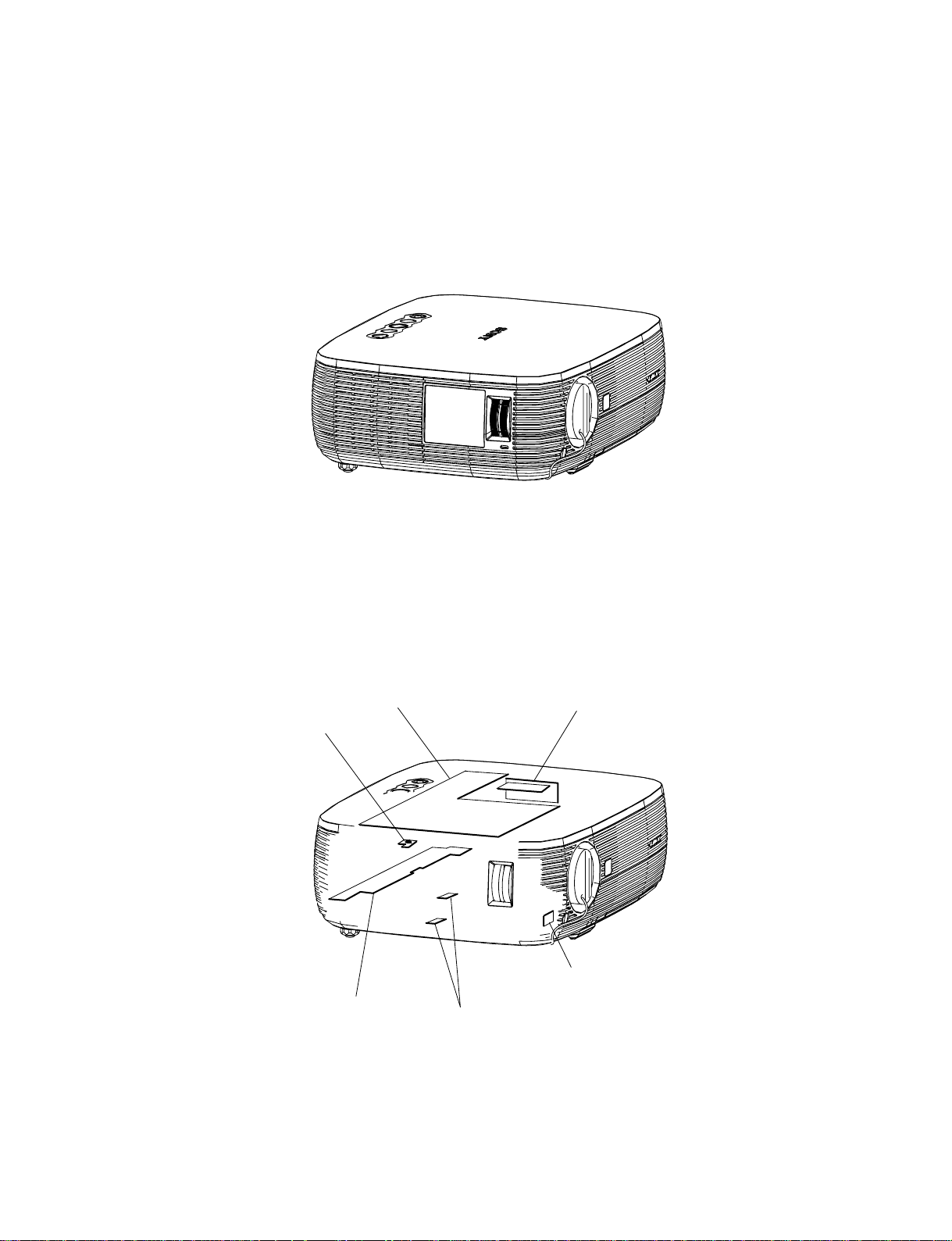
1-1. Appearance Figure
Section 1
Service Information
1-2. Board Locations
Thermal sennsor
Power
Main
Detection switch
Lamp power supply
IR sensor
VPL-ES3
1-1
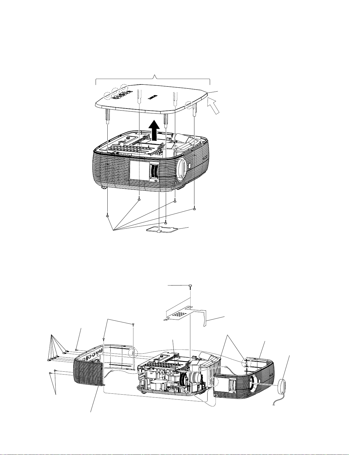
1-3. Disassembly
1-3-1. Upper Case Assembly
3
Four claws
4 Upper Case assembly
Remove the Upper Case from this corner with the
strong force to the extent that the Upper Case will
not be damaged.
1
Filter door
2
Five screws
(M 3 x 6)
1-3-2. Front Case Assembly and Sub Rear Case Assembly
2
Two screws
(M 3 x 6)
7
Two screws
(M 3 x 6)
crew (M 3)
Main board
J6
5
Six
hexagon
screws
6 Flat head
s
8
Two claws
J11
3 Shield
0
Front case assembly
1
Lens cap
1-2
4
Two screws
(+K 3 x 12)
9
Sub rear case assembly
VPL-ES3
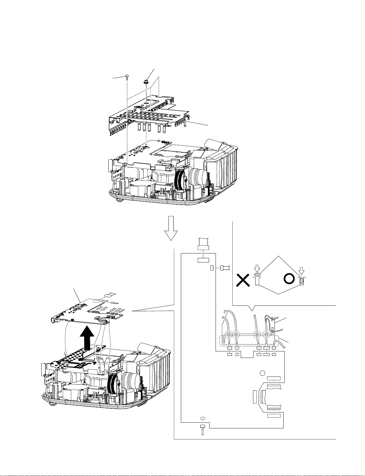
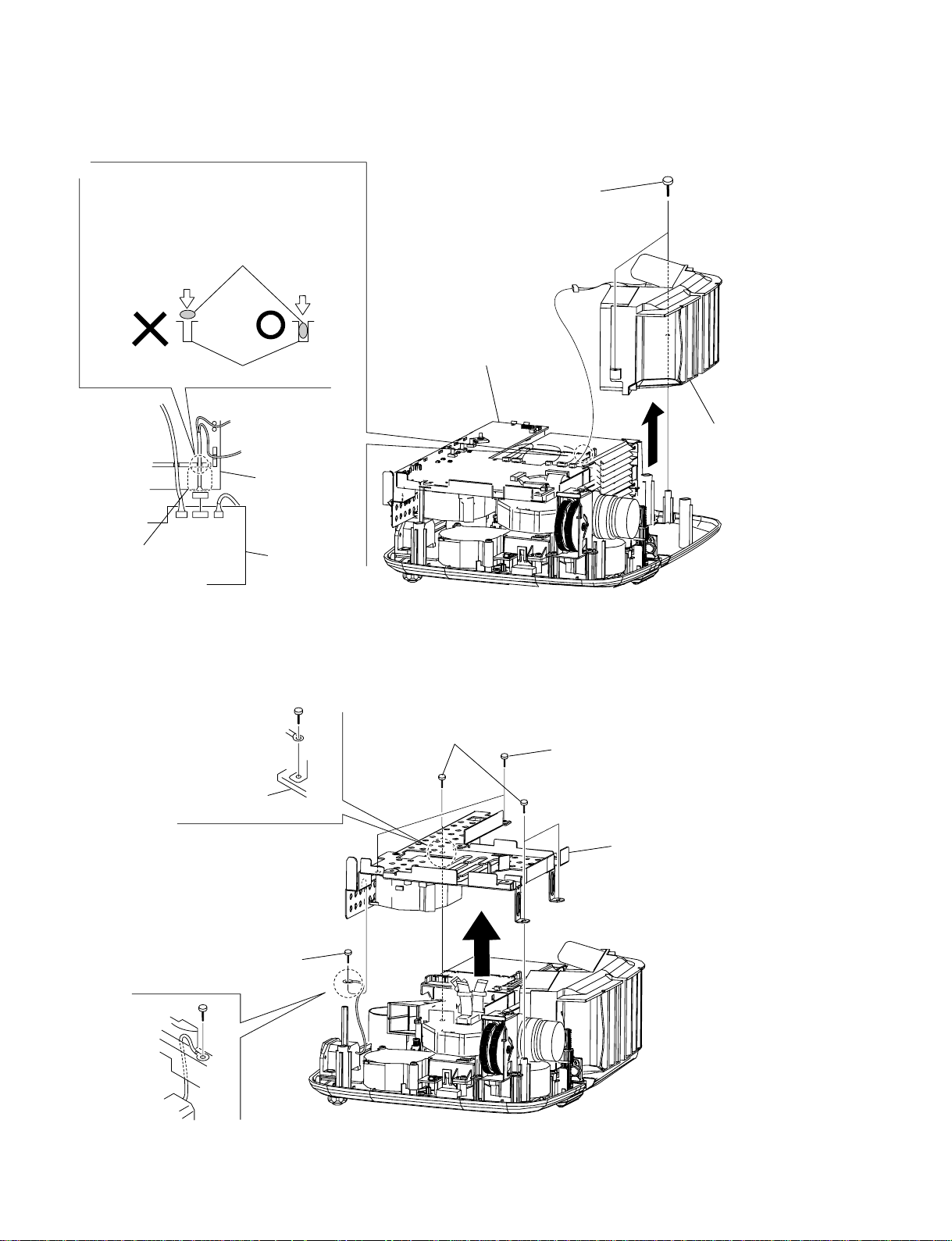
1-3-3. Main Board
1
Three screws
(M 3 x 6)
2
Joystick key
J19
J12
3
Main shield
Because the harnesses has the shape of flat
cross-section, do not insert the harnesses with
excessive force. Find out the direction in
which the harnesses can be inserted easily,
and then insert the harnesses.
Harnesses
VPL-ES3
4
Main board
Main board
J14
J13
J17
Harnesses clamp section
J24 J16 J18
J22
J21
J20
Lamp box assembly
When re-assembling,
give an appropriate
amount of extra slack
of this harnesses.
1-3
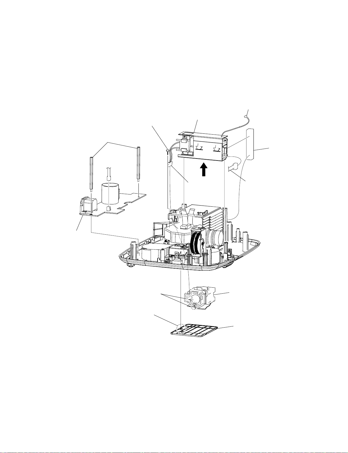
1-3-4. Tunnel Outlet Section
Because the harnesses has the shape of flat
cross-section, do not insert the harnesses with
excessive force. Find out the direction in
which the harnesses can be inserted easily,
and then insert the harnesses.
Harnesses
Harnesses clamp section
Lamp box
assembly
J16
When re-assembling,
give an appropriate
amount of extra slack
of this harnesses.
Main board
1
Two tapping screws
(PAN 3 x 7)
Main board
J16
2
Tunnel outlet section
1-3-5. Main Board Bracket Section
Remove the Main board before starting the removal work
2
Three tapping screws
(PAN 3 x 7)
Power board
3 S
crew
(M 4 x 6)
1
Two screws
(M 3 x 6)
4
Main board bracket section
1-4
VPL-ES3
1-3-6. Power Board and Lamp Power Supply
Remove the Tunnel Outlet unit before starting the removal work.
n
In older to remove the connector that is connected to the lamp power supply block, remove the lamp
power supply first. Then, remove the connector after the lamp power supply block is raise up. Do not give
an excessive force to the harness.
To the main board J12
0
Lamp power supply
9
1 Two
3 Screw
(+PWH 3 x 8)
stands assembly
CN603
Cushion
2
Power board
6
Loosen two screws.
4
loosen screw.
8
Lamp power
supply
connector
From the Main board CN602
(Red and Black wires)
7
Lamp
5
Lamp door
VPL-ES3
1-5
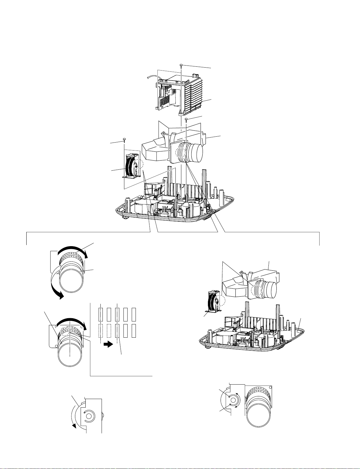
1-3-7. Optics Section
1
Two tapping screws
(PAN 3 x 7)
2
Lamp box assembly
5
Four screws
(+P 2.5 x 8)
3
Two tapping screws
(PAN 3 x 7)
4
Focus/Zoom adjust
assembly
Assembling Method of Optics section and
Focus/Zoom Adjust Assembly
Phase matching
1
Rotate the Zoom dial clockwise
as shown until it is stopped.
2
Rotate the Focus dial
counter-clockwise as
shown until it is stopped.
6 Optics
During the assembling process,
never change the gear position
that is set by step
3
section
Install the Optics section
.
5
in the Lower Case.
Focus dial
4
Rotate the Focus/Zoom Adjust Assembly
counter-clockwise until it is stopped.
1-6
3
Rotate the Focus dial
counter-clockwise as
shown until it is stopped.
6
Install the Focus/Zoom
Adjust Assembly as shown.
7 After installation is completed, verify that the Optics
section can rotate from the position A to the position
B smoothly.
A
B
Lower case
VPL-ES3
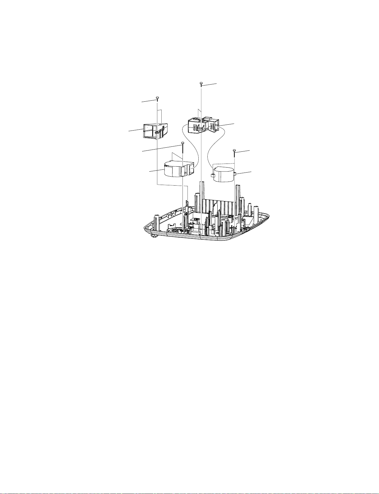
1-3-8. DC Fan
7
Two tapping screws
(PAN 3 x 7)
8
Duct lamp
5
Two tapping screws
(M 3 x 25)
1
Two tapping screws
(PAN 3 x 7)
2
Duct
LCD assembly
3
Two tapping screws
(+PWH 3 x 10)
6 DC fan
4 DC fan
VPL-ES3
1-7
 Loading...