

Sony VPL-ES3 User Manual
Data Projector
Operating Instructions
2-672-629-13 (1)
VPL-ES3
VPL-EX3
© 2006 Sony Corporation

WARNING
To reduce the risk of fire or electric
shock, do not expose this apparatus
to rain or moisture.
To avoid electrical shock, do not open
the cabinet. Refer servicing to
qualified personnel only.
WARNING
THIS APPARATUS MUST BE
EARTHED.
IMPORTANT
The nameplate is located on the bottom.
WARNING
This unit has no power switch.
When installing the unit, incorporate a
readily accessible disconnect device in the
fixed wiring, or connect the power cord to
socket-outlet which must be provided near
the unit and easily accessible.
If a fault should occur during operation of
the unit, operate the disconnect device to
switch the power supply off, or disconnect
the power cord.
CAUTION
Danger of explosion if battery is incorrectly
replaced.
Replace only with the same or equivalent
type recommended by the manufacturer.
Dispose of used batteries according to the
manufacturer’s instructions.
For the customers in the USA
This equipment has been tested and found to
comply with the limits for a Class B digital
device, pursuant to Part 15 of the FCC Rules.
These limits are designed to provide
reasonable protection against harmful
interference in a residential installation.
This equipment generates, uses, and can
radiate radio frequency energy and, if not
installed and used in accordance with the
instructions, may cause harmful interference
to radio communications. However, there is
no guarantee that interference will not occur
in a particular installation. If this equipment
does cause harmful interference to radio or
television reception, which can be
determined by turning the equipment off and
on, the user is encouraged to try to correct
the interference by one or more of the
following measures:
– Reorient or relocate the receiving antenna.
– Increase the separation between the
equipment and receiver.
– Connect the equipment into an outlet on a
circuit different from that to which the
receiver is connected.
– Consult the dealer or an experienced radio/
TV technician for help.
You are cautioned that any changes or
modifications not expressly approved in this
manual could void your authority to operate
this equipment.
All interface cables used to connect
peripherals must be shielded in order to
comply with the limits for a digital device
pursuant to Subpart B of Part 15 of FCC
Rules.
This device complies with Part 15 of the
FCC Rules. Operation is subject to the
following two conditions: (1) This device
may not cause harmful interference, and (2)
this device must accept any interference
received, including interference that may
cause undesired operation.
If you have any questions about this product,
you may call:
Sony Customer Information Service Center
1-800-222-7669 or http://www.sony.com/
The number below is for FCC related
matters only.
Declaration of Conformity
Trade N ame: SONY
Model: VPL-ES3, VPL-EX3
Responsible Party: Sony Electronics Inc.
Address: 16530 Via Esprillo,
San Diego, CA 92127 U.S.A.
Telephone Number: 858-942-2230
WARNING: THIS WARNING IS
APPLICABLE FOR USA ONLY.
If used in USA, use the UL LISTED power
cord specified below.
2
WARNING
DO NOT USE ANY OTHER POWER
CORD.
Plug Cap Parallel blade with ground pin
(NEMA 5-15P Configuration)
Cord Type SJT, three 16 or 18 AWG
wires
Length Minimum 1.5m (4 ft .11in.), Less
than 2.5 m (8 ft .3 in.)
Rating Minimum 10A, 125V
Using this unit at a voltage other than 120V
may require the use of a different line cord or
attachment plug, or both.
To reduce the risk of fire or electric shock,
refer servicing to qualified service
personnel.
WA R N I NG : THIS WARNING IS
APPLICABLE FOR OTHER
COUNTRIES.
1. Use the approved Power Cord (3-core
mains lead) / Appliance Connector / Plug
with earthing-contacts that conforms to
the safety regulations of each country if
applicable.
2. Use the Power Cord (3-core mains lead) /
Appliance Connector / Plug conforming
to the proper ratings (Voltage, Ampere).
Disposal of Old Electrical &
Electronic Equipment (Applicable in
the European Union and other
European countries with separate
collection systems)
This symbol on the product or
on its packaging indicates that
this product shall not be treated
as household waste. Instead it
shall be handed over to the
applicable collection point for
the recycling of electrical and
electronic equipment. By ensuring this
product is disposed of correctly, you will
help prevent potential negative
consequences for the environment and
human health, which could otherwise be
caused by inappropriate waste handling of
this product. The recycling of materials will
help to conserve natural resources. For more
detailed information about recycling of this
product, please contact your local city office,
your household waste disposal service or the
shop where you purchased the product.
For the customers in Taiwan only
If you have questions on the use of the above
Power Cord /Appliance Connector /Plug,
please consult a qualified service personnel.
Voor de klanten in Nederland
• Gooi de batterij niet weg maar lever deze
in als klein chemisch afval (KCA).
• Dit apparaat bevat een vast ingebouwde
batterij die niet vervangen hoeft te worden
tijdens de levensduur van het apparaat.
• Raadpleeg uw leverancier indien de
batterij toch vervangen moet worden.
De batterij mag alleen vervangen worden
door vakbekwaam servicepersoneel.
• Lever het apparaat aan het einde van de
levensduur in voor recycling, de batterij
zal dan op correcte wijze verwerkt
worden.
WARNING
3

Table of Contents
Precautions ......................................... 5
Notes on Installation and Usage ........ 6
Overview
Features ..............................................8
Location and Function of Controls .... 9
Top/Right Side/Front .................... 9
Rear/Bottom ................................. 9
Control Panel ..............................10
Connector Panel .........................11
Remote Commander ...................11
Projecting the Picture
Installing the Projector ..................... 13
Connecting the Projector ................. 14
Connecting a Computer ..............14
Connecting a VCR .....................15
Projecting ......................................... 16
Turning Off the Power ..................... 18
The INSTALL SETTING Menu .......31
The INFORMATION Menu .............32
Maintenance
Replacing the Lamp ..........................34
Cleaning the Air Filter ......................36
Others
Troubleshooting ................................37
Messages List ..............................39
Specifications ...................................41
Installation Diagram .........................46
Floor Installation (Front
Projection) ...............................46
Ceiling Installation (Front
Projection) ...............................48
Dimensions .......................................50
Index .................................................51
Convenient Functions
Selecting the Menu Language .......... 19
Security Lock ...................................20
Effective Tools for Your
Presentation .................................. 21
Adjustments and Settings
Using a Menu
Using a MENU ................................23
The PICTURE SETTING Menu ...... 25
The INPUT SETTING Menu .......... 26
About the Preset Memory No. ...27
The SET SETTING Menu ............... 28
The MENU SETTING Menu .......... 30
4
Table of Contents

Precautions
Safety
• Check that the operating voltage of your
unit is identical with the voltage of your
local power supply.
• Should any liquid or solid object fall into
the cabinet, unplug the unit and have it
checked by qualified personnel before
operating it further.
• Unplug the unit from the wall outlet if it is
not to be used for several days.
• To disconnect the cord, pull it out by the
plug. Never pull the cord itself.
• The wall outlet should be near the unit and
easily accessible.
• The unit is not disconnected to the AC
power source (mains) as long as it is
connected to the wall outlet, even if the
unit itself has been turned off.
• Do not look into the lens while the lamp is
on.
• Do not place your hand or objects near the
ventilation holes. The air coming out is
hot.
• Be careful not to get your fingers caught in
the adjuster.
• Do not spread a cloth or paper under the
unit.
Illumination
• To obtain the best picture, the front of the
screen should not be exposed to direct
lighting or sunlight.
• Ceiling-mounted spot lighting is
recommended. Use a cover over
fluorescent lamps to avoid lowering the
contrast ratio.
• Cover any windows that face the screen
with opaque draperies.
• It is desirable to install the unit in a room
where floor and walls are not of lightreflecting material. If the floor and walls
are of reflecting material, it is
recommended that the carpet and wall
paper be changed to a dark color.
Preventing internal heat build-up
After you turn off the power with the ?/1
key, do not disconnect the unit from the wall
outlet while the cooling fan is still running.
Caution
The unit is equipped with ventilation holes
(intake) and ventilation holes (exhaust). Do
not block or place anything near these holes,
or internal heat build-up may occur, causing
picture degradation or damage to the
projector.
Cleaning
• To keep the cabinet looking new,
periodically clean it with a soft cloth.
Stubborn stains may be removed with a
cloth lightly dampened with a mild
detergent solution. Never use strong
solvents, such as thinner, benzene, or
abrasive cleansers, since these will
damage the cabinet.
• Avoid touching the lens. To remove dust
on the lens, use a soft dry cloth. Do not use
a damp cloth, detergent solution, or
thinner.
• Clean the filter at regular intervals.
LCD data projector
• This LCD data projector is manufactured
using high-pre cision technology. You may,
however, see tiny black points and/or
bright points (red, blue, or green) that
appear continuously on the LCD data
projector. This is a normal result of the
manufacturing process and does not
indicate a malfunction.
Precautions
5
Notes on Installation and Usage
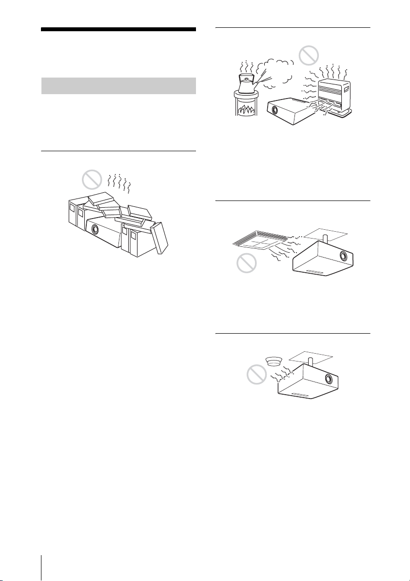
Unsuitable Installation
Do not install the projector in the following
situations. Installation is these situations
or locations may cause a malfunction or
damage to the unit.
Poorly ventilated locations
• Allow adequate air circulation to prevent
internal heat build-up. Do not place the
unit on surfaces (rugs, blankets, etc.) or
near materials (curtains, draperies) that
may block the ventilation holes. When
internal heat builds up due to blockage of
ventilation holes, the temperature sensor
will function, and the power will be turned
off automatically.
• Leave space of more than 30 cm (11
inches) around the unit.
• Be careful not to allow the ventilation
holes to inhale tiny objects such as pieces
of paper or clumps of dust.
7
/8
Hot and humid
• Avoid installing the unit in a location
where the temperature or humidity is very
high, or the temperature is very low.
• To avoid moisture condensation, do not
install the unit in a location where the
temperature may rise rapidly.
Locations subject to direct cool or
warm air from an air-conditioner
Installing the projector in such a location
may cause a malfunction of the unit due to
moisture condensation or a rise in
temperature.
Near a heat or smoke sensor
6
Notes on Installation and Usage
Malfunction of the sensor may occur.
Very dusty, extremely smoky
locations
Blocking the ventilation holes
Avoid installing the unit in a very dusty or
extremely smoky environment. Otherwise,
the air filter will become obstructed, and this
may cause a malfunction of the unit or
damage it. Dust preventing the air passing
through the filter may cause a rise in the
internal temperature of the unit. Clean the
filter periodically.
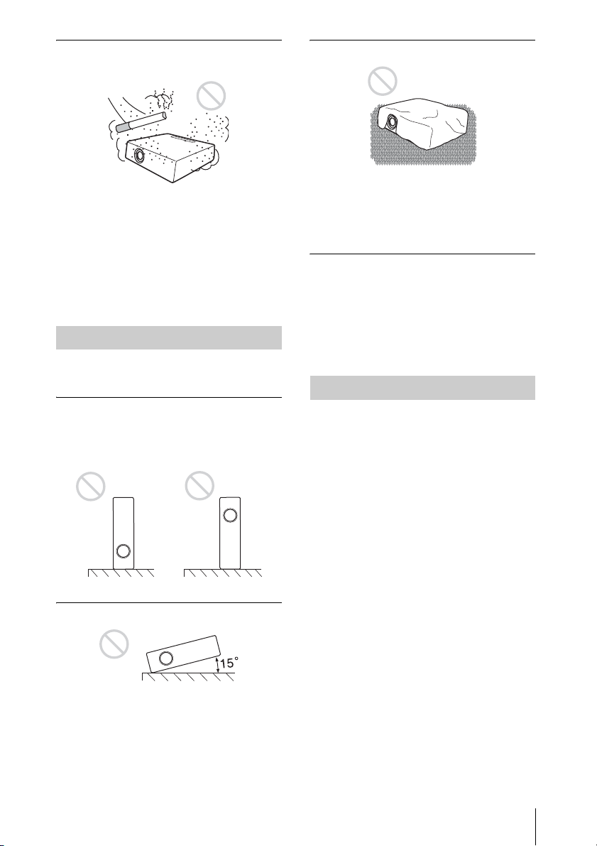
Unsuitable Conditions
Do not use the projector under the following
conditions.
Standing the unit upright on one
side
Avoid using the unit standing upright on its
side. It may cause malfunction.
Tilting the unit to the right or left
Avoid using a thick-piled carpet or anything
that covers the ventilation holes (exhaust/
intake); otherwise, internal heat may build
up.
Placing a blocking object just in
front of the lens
Do not place any object just in front of the
lens that may block the light during
projection. Heat from the light may damage
the object. Use the PIC MUTING key on the
Remote Commander to cut off the picture.
Usage at High Altitude
When using the projector at an altitude of
1,500 m or higher, turn on “High
Altitude Mode” in the INSTALL SETTING
menu. Failing to set this mode when using
the projector at high altitudes could have
adverse effects, such as reducing
the reliability of certain components.
Note on carrying the projector
The unit is manufactured using highprecision technology. When transporting the
unit stored in the carrying case, do not drop
the unit or subject it to shock, as this may
cause damage. When storing the unit in the
carrying case, disconnect the AC power cord
and all other connecting cables or cards, and
store the supplied accessories in a pocket of
the carrying case.
Avoid tilting the unit to an angle of 15°, and
avoid installing the unit in any way other
than placing it on a level surface or
suspending from the ceiling. Such an
installation may cause color shading or
shorten the lamp life excessively.
Note on the screen
When using a screen with an uneven surface,
a striped pattern may rarely appear on the
screen depending on the distance between
the screen and the projector or the zooming
magnification settings used. This is not a
malfunction of the projector.
Notes on Installation and Usage
7

B Overview
Features
prevents the projector from operating
incorrectly.
High brightness, high picture
quality
High brightness
Adopting Sony's unique optical system that
provides a high-efficiency optical system. It
allows the 165 W lamp to give a light output
of 2000 ANSI lumen.
High picture quality
VPL-ES3: Three super-high-aperture 0.63inch SVGA panels with approximately
480,000 effective pixels, produce a
resolution of 800 × 600 dots (horizontal/
vertical) for RGB input, and 500 horizontal
TV lines for video input.
VPL-EX3: Three super-high-aperture 0.63inch XGA panels with approximately
790,000 effective pixels, produce a
resolution of 1024 × 768 dots (horizontal/
vertical) for RGB input, and 750 horizontal
TV lines for video input.
Quiet presentation environment
Low fan noise reduces distraction allowing
you to run an optimum presentation even in
a quiet environment.
About Trademarks
• Adobe Acrobat is a trademark of Adobe
Systems Incorporated.
• Windows is a registered trademark of
Microsoft Corporation in the United States
and/or other countries.
• VGA, SVGA, XGA and SXGA are
registered trademarks of the International
Business Machines Corporation, U.S.A.
• Kensington is a registered trademark of
Kensington Technology Group.
• Macintosh is a registered trademark of
Apple Computer, Inc.
• VESA is a registered trademark of the
Video Electronics Standard Association.
• Display Data Channel is a trademark of the
Video Electronics Standard Association.
Short focal lens
The projection distance is very short,
approximately 2.3 m (7.5 feet), when
projecting an 80-inch image, which allows
projection on a larger screen even in a
limited space.
Security Functions
Security lock
This function makes it possible to prevent
projection of a picture on the screen unless
the required password is entered when the
projector is turned on.
Panel key lock
This function locks all the keys on the
control panel of the projector, allowing use
of the keys on the Remote Commander. This
8
Features
Location and
7
Function of Controls
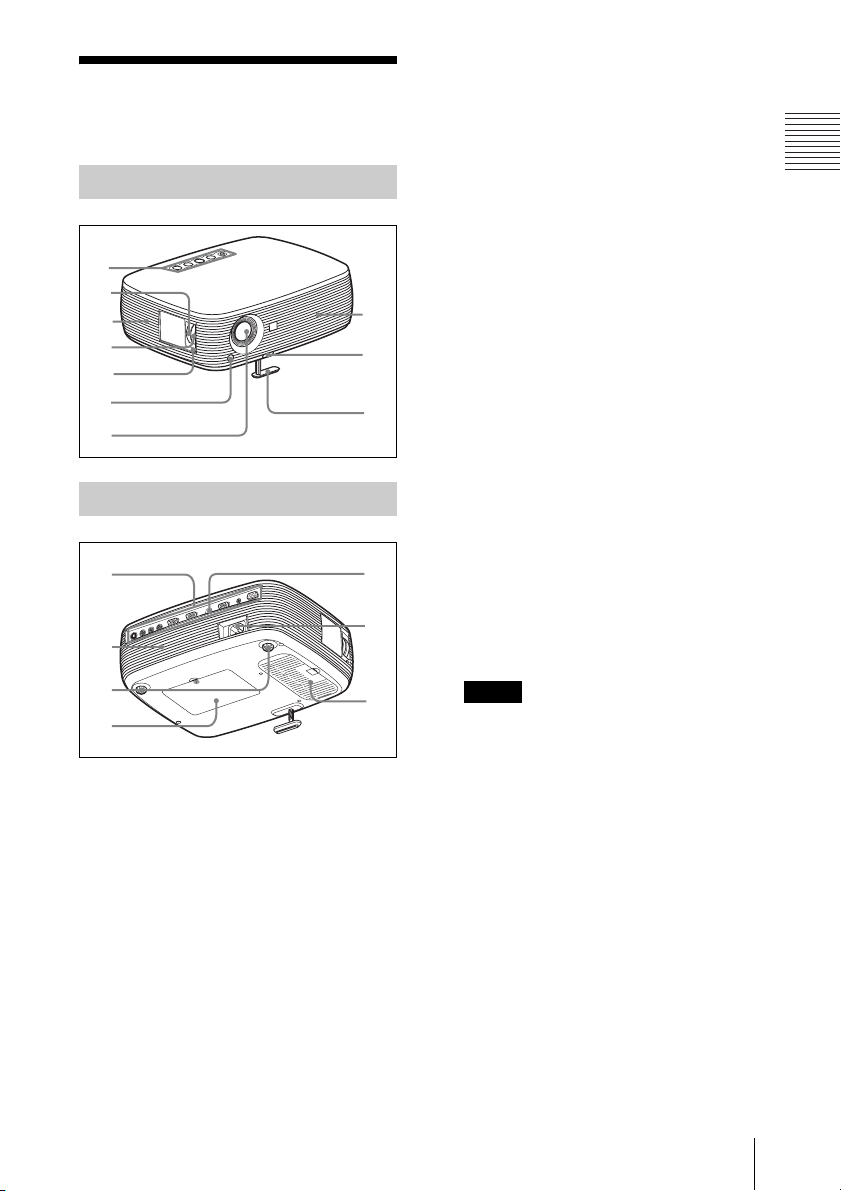
Top/Right Side/Front
1
2
3
4
5
6
8
9
0
f Front remote control detector
g Lens
Remove the lens cover before
projection.
h Ventilation holes (exhaust)
i Adjuster adjustment button
For details, see “Using the adjuster” on
page 17.
j Adjuster
k Connector Panel
For details, see “Connector Panel” on
page 11.
l Speaker
m Adjusters (hind pad)
Overview
Rear/Bottom
qa
qs
qd
qf
a Control panel
For details, see “Control Panel” on
page 10.
b Zoom ring
Adjusts the picture size.
c Ventilation holes (intake)
d Focus ring
Adjusts the picture focus.
e Security lock
Connects to an optional security cable
(from Kensington).
Web page address:
http://www.kensington.com/
qg
qh
qj
n Lamp cover
o Rear remote control detector
p AC IN socket
Connects the supplied AC power cord.
q Ventilation holes (intake)/Air
filter cover
Notes
• Do not place anything near the
ventilation holes as this may cause
internal heat build-up.
• Do not place your hand near the
ventilation holes as this may cause
injury.
• To maintain optimal performance, clean
the air filter every 500 hours.
For details, see “Cleaning the Air
Filter” on page 36.
Location and Function of Controls
9
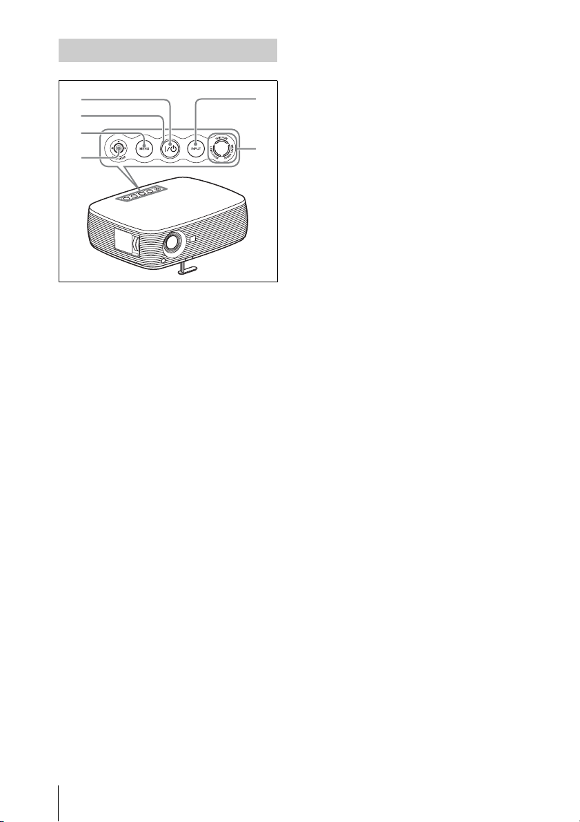
Control Panel
1
5
2
3
4
a ?/1 (On/Standby) key
Turns on the projector when the
projector is in standby mode. The ON/
STANDBY indicator around the ?/1 key
flashes in green until the projector is
ready to operate.
b ON/STANDBY indicator (located
around the
Lights up or flashes under the following
conditions:
– Lights in red when the AC power cord
is plugged into a wall outlet. Once the
projector is in standby mode, you can
turn it on with the ?/1 key.
– Lights in green when the power is
turned on, and when it is ready to
operate.
– Flashes in green from the projector is
turned on until the projector is ready to
operate. Also, flashes in green while
the cooling fan is running after the
power is turned off with the ?/1 key.
The fan runs for about 90 seconds after
the power is turned off.
For detail on the ?/1 indicator, see
page 18.
?/1 key)
6
d PUSH ENTER/v/V/b/B (Arrow)
keys
Used to enter the settings of items in the
menu system, select a menu, or make
various adjustments.
e INPUT key
f Status indicators
• POWER SAVING
Lights when the projector is in power
saving mode.
• TEMP (Temperature)/FAN
Lights or flashes under the following
conditions:
– Lights when the temperature inside
the projector becomes unusually
high.
– Flashes when the fan is broken.
• LAMP/COVER
Lights or flashes under the following
conditions:
– Lights when the lamp has reached
the end of its life or reaches a high
temperature.
– Flashes when the lamp cover or air
filter cover is not secured firmly.
For details, see page 39.
c MENU key
Displays the on-screen menu. Press
again to clear the menu.
10
Location and Function of Controls
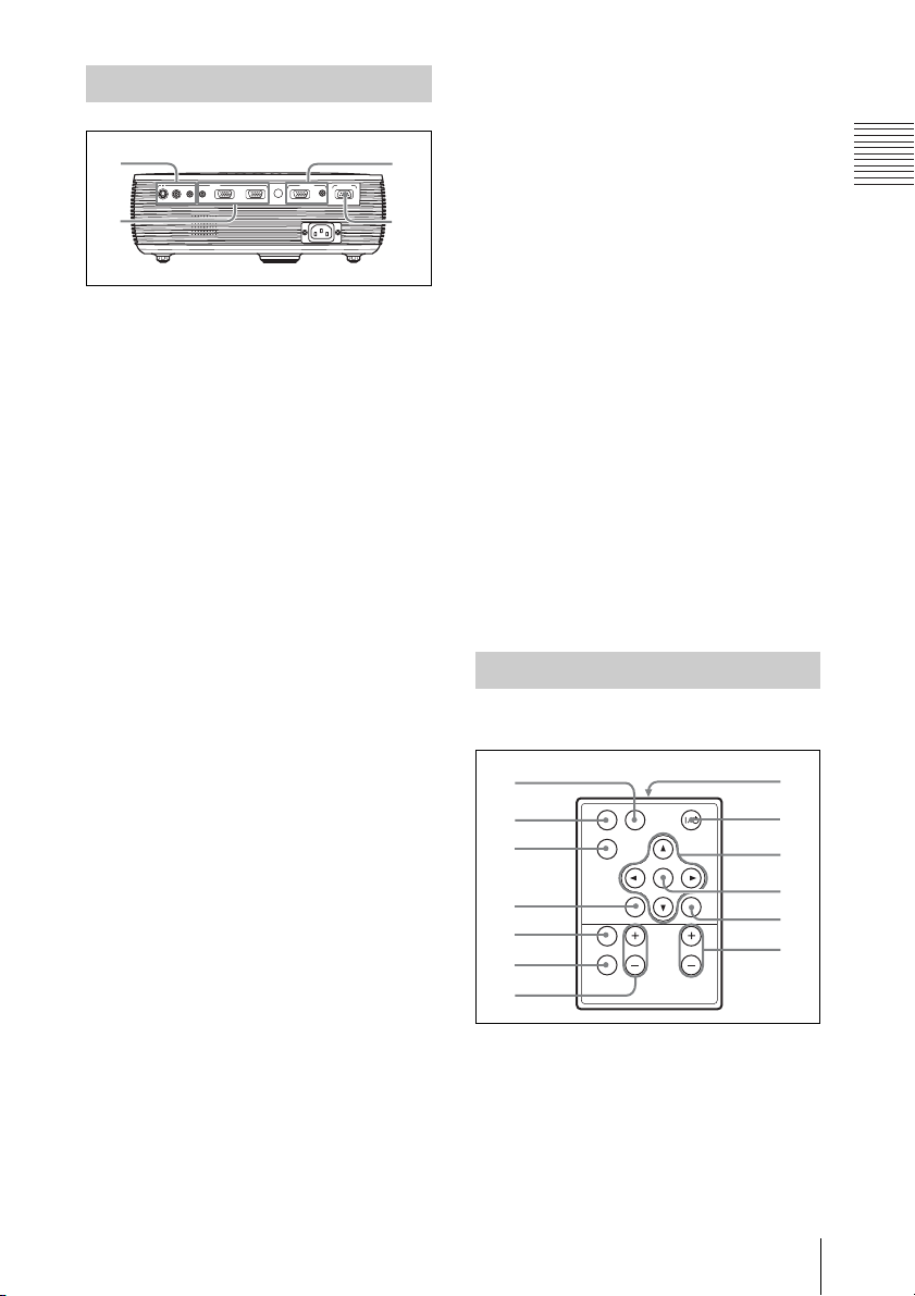
Connector Panel
1
INPUT OUTPUT REMOTE
AUDIO
INPUT A
S VIDEO VIDEO AUDIO
INPUT A/B
INPUT B MONITOR AUDIO RS232C
2
a VIDEO INPUT connector
• S VIDEO (mini DIN 4-pin):
Connects to the S video output (Y/C
video output) of video equipment.
• VIDEO (phono type): Connects to
the composite video output of video
equipment.
• AUDIO jack (stereo minijack): To
listen to sound output from video
equipment, connect via this jack to the
audio output of the video equipment.
To listen to sound output from a
computer with the VPL-ES3, connect
via this jack to the audio output of the
computer.
b INPUT connector
• AUDIO INPUT A/B jack (stereo
minijack) (for VPL-EX3 only): To
listen to sound output from a
computer, connect via this jack to the
audio output of the computer.
(common INPUT A/B)
• INPUT A (HD D-sub 15-pin,
female): Inputs a computer signal,
video GBR signal, component signal,
or DTV signal depending on the
connected equipment.
Connects to the output connector of
equipment using the supplied cable or
an optional cable.
For details, see “Connecting a
Computer” on page 14 and
“Connecting a VCR” on page 15.
• INPUT B connector (HD D-sub 15pin) (for VPL-EX3 only): Connect to
external equipment such as a
computer.Connect to the monitor
output of a computer.
3
4
c OUTPUT connector
• MONITOR (HD D-sub 15-pin,
female): Connect to the video input
connector of the monitor. Outputs
signals from the selected channel and
computer signals only from among the
signals from the INPUT A or INPUT
B (VPL-EX3 only).
• AUDIO (stereo minijack): Connects
to external active speakers. The
volume of the speakers can be
controlled by the VOLUME +/– keys
on the Remote Commander.
For the VPL-EX3, when INPUT A or
INPUT B is selected, the sound input
to the AUDIO (AUDIO INPUT A/B)
connector which is common for
INPUT A/B is output.
When VIDEO or S VIDEO is selected,
the sound input to the AUDIO input
connector of VIDEO IN is output.
d RS-232C connector (D-sub 9-
pin, female)
Connects to a computer to operate the
projector from the computer.
Remote Commander
The keys that have the same names as those
on the control panel function identically.
1
2
3
4
5
6
APA
INPUT
KEY
STONE
RESET
PIC
MUTING
D ZOOM VOLUME
FREEZE
ENTER
MENU
8
9
0
qa
qs
qd
7
a INPUT key
b APA (Auto Pixel Alignment) key
Automatically adjusts a picture to its
clearest while a signal is input from a
computer.
For details, see “Smart APA” in “The
SET SETTING Menu” on page 28.
Overview
Location and Function of Controls
11
c KEYSTONE (Trapezoidal
distortion correction) key
Adjusts the vertical trapezoidal
distortion of the image. Pressing this
key, the adjustment menu are displayed.
Use the arrow keys (v/V/b/B) for
adjustment.
d RESET key
Resets the value of an item to its factory
preset value or returns the enlarged
image to its original size. This key
functions when the menu or a setting
item is displayed on the screen.
e PIC MUTING key
Cuts off the picture. Press again to
restore the picture.
f FREEZE key
Freezes the projected picture. To cancel
the frozen picture, press the key again.
g D ZOOM (Digital Zoom) +/– key
Enlarges the image at a desired location
on the screen.
h Infrared transmitter
i ?/1 (On/Standby) key
v/V/b/B (Arrow) keys
j
k ENTER key
l MENU key
m VOLUME +/– keys
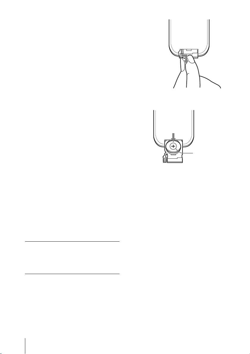
Before using the Remote
Commander
Pull out the clear film from the lithium
battery holder.
To replace a battery
1 Release the lock of the lithium battery
holder by picking it, and pull out the
holder from the Remote Commander.
2 Install the lithium battery.
Face th e +
side up.
3 Put the lithium battery holder back
into the Remote Commander.
Notes on the lithium battery
• A button type lithium battery (CR2025) is
used in the Remote Commander. Do not
use batteries other than CR2025.
• Keep the lithium battery out of the reach of
children.
• Should the battery be swallowed,
immediately consult a doctor.
Notes on Remote Commander
operation
• Make sure that nothing obstructs the
infrared beam between the Remote
Commander and the remote control
detector on the projector. Direct the
Remote Commander toward the remote
control detector.
• The operation range is limited. The shorter
the distance between the Remote
Commander and the remote control
detector is, the wider the angle within
which the commander can control the
projector becomes.
12
Location and Function of Controls
B Projecting the Picture
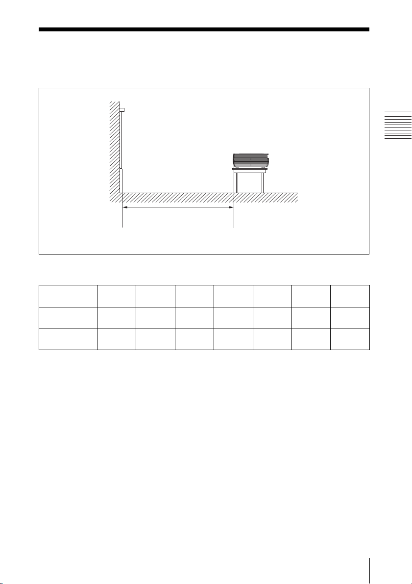
Installing the Projector
The distance between the lens and the screen varies depending on the size of the screen. Use
the following table as a guide.
Screen
Distance between the screen
and the center of the lens
Unit: m (feet)
Screen size
(inches)
Minimum
Distance
Maximum
Distance
There may be a slight difference between the actual value and the design value shown in the table
above.
40 80 100 150 200 250 300
1.2
(3.9)
1.4
(4.6)
2.3
(7.5)
2.8
(9.2)
2.9
(9.5)
3.6
(11.8)
4.4
(14.4)
5.4
(17.7)
5.9
(19.4)
7.2
(23.6)
7.3
(24)
9.0
(29.5)
(28.9)
(35.1)
8.8
10.7
Projecting the Picture
For details on installation diagram, see “Installation Diagram” on page 46.
Installing the Projector
13
Connecting the
P
Projector
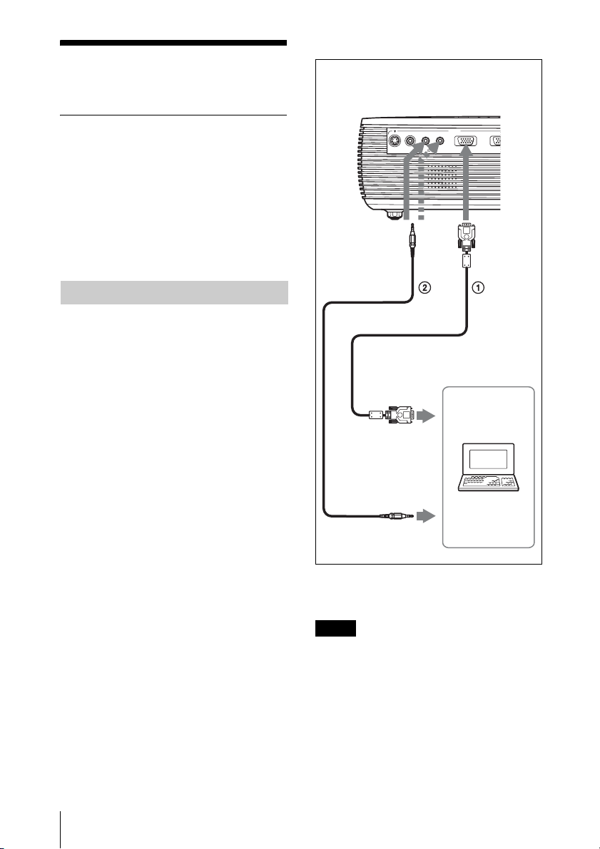
To connect a computer
Rear side
When you connect the projector,
make sure to:
• Turn off all equipment before making any
connections.
• Use the proper cables for each connection.
• Insert the cable plugs firmly; loose
connections may increase noise and
reduce performance of picture signals.
When pulling out a cable, be sure to pull it
out by the plug, not the cable itself.
Connecting a Computer
This section describes how to connect the
projector to a computer.
For more information, refer to the
computer’s instruction manual.
S VIDEO VIDEO AUDIO
to monitor output
to audio output
AUDIO
INPUT A/B
INPUT
INPUT A
Computer
IN
14
Connecting the Projector
1 HD D-sub 15-pin cable (supplied)
2 Stereo audio connecting cable (not supplied)
(Use a no-resistance cable.)
Notes
• For stereo audio connection, connect the
stereo audio connecting cable to the AUDIO
connector for VPL-ES3, or to the AUDIO
INPUT A/B connector for VPL-EX3.
• The projector accepts VGA, SVGA, XGA,
SXGA, and SXGA+ signals. However, we
recommend that you set the output mode of
your computer to SVGA (VPL-ES3) or XGA
(VPL-EX3) mode for the external monitor.
• If you set your computer, such as a notebook
computer, to output the signal to both your
computer’s display and the external monitor,
P
the picture of the external monitor may not
appear properly. Set your computer to output
the signal to only the external monitor.
For details, refer to the operating
instructions supplied with your computer.
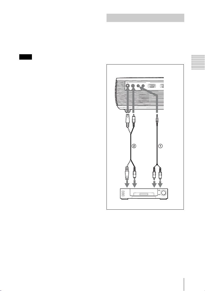
Connecting a VCR
This section describes how to connect the
projector to a VCR.
For more information, refer to the
instruction manuals of the equipment you
are connecting.
Note
To connect a Macintosh computer equipped
with a video output connector of a type having
two rows of pins, use a commercially available
plug adaptor.
To connect to a video or S video
output connector
Rear side
INPUT
AUDIO
INPUT A
IN
to audio
output (R)
to S
video
output
S VIDEO VIDEO AUDIO
INPUT A/B
to audio
output (L)
to video
output
Projecting the Picture
VCR
1 Stereo audio connecting cable (not supplied)
(Use a no-resistance cable.)
2 Video cable (not supplied) or S-Video cable
(not supplied)
Connecting the Projector
15
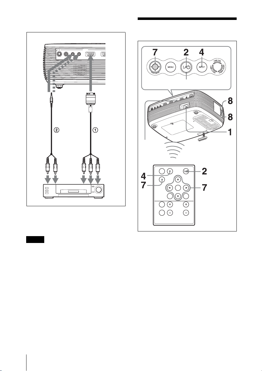
To connect to a video GBR/
P
Component output connector
Rear side
INPUT
AUDIO
INPUT A
S VIDEO VIDEO AUDIO
to
audio
output
(L)
INPUT A/B
to
audio
output
(R)
VCR
1 Signal Cable (not supplied)
HD D-sub 15-pin (male) ↔ 3 × phono jack
2 Stereo audio connecting cable (not supplied)
(Use a no-resistance cable.)
IN
to video
GBR/
component
output
Projecting
Rear
remote
control
detector
ON/STANDBY indicator
APA
INPUT
KEY
STONE
ENTER
RESET
MENU
PIC
MUTING
D ZOOM VOLUME
FREEZE
Notes
• For stereo audio connection, connect the
stereo audio connecting cable to the AUDIO
connector for VPL-ES3, or to the AUDIO
INPUT A/B connector for VPL-EX3.
• Set the aspect ratio using “Wide Mode” on
the INPUT SETTING menu according to the
input signal.
• When you connect the projector to a video
GBR output connector, select “Video GBR”
or when you connect the projector to a
component output connector, select
“Component” with the “Input-A Signal Sel.”
setting on the SET SETTING menu.
• Use the composite sync signal when you
input the external sync signal from video
GBR/component equipment.
16
Projecting
1 Plug the AC power cord into a wall
outlet, and connect all equipment, then
remove the lens cover.
The ON/STANDBY indicator lights in
red and the projector goes into standby
mode.
2 Press the ?/1 key.
The ON/STANDBY indicator lights
after flashing in green. The projector
cannot be used while the ON/
STANDBY indicator is flashing.
3 Turn on the equipment connected to
the projector.
 Loading...