


UHF Synthesized
4-590-342-11 (1)
Transmitter
Operating Instructions
UTX-B03HR
© 2016 Sony Corporation

Table of Contents
Features .......................................................3
Parts Identification......................................3
Power Supply...............................................5
Inserting the Batteries ................................... 5
Supplying Power from a USB Connector..... 6
Charging Nickel Metal Hydride Batteries .... 6
Preparation ..................................................7
Connecting a Lavalier Microphone .............. 7
Attaching a Belt Clip .................................... 7
Settings ........................................................8
Setting the Transmit Channel ....................... 8
Setting the Compander Mode ....................... 9
Using the Infrared Communication
Function............................................... 9
Menu Displays and Detailed Settings......10
Menu Structure and Operation.................... 10
Configuration Menu.................................... 11
Error Messages .........................................13
Troubleshooting ........................................14
Important Notes on Use............................16
Usage and Storage ...................................... 16
Cleaning...................................................... 16
Specifications............................................16
2
Features
The UTX-B03HR UHF Synthesized Transmitter is a
body-pack transmitter equipped with an SMC9-4S
connector designed for high reliability.
Reliable and proven SMC9-4S (female) interface
The unit is compatible with Sony ECM-77BC and ECM44BC lavalier microphones, which have a proven record
of reliable performance in broadcasting.
Digital companding
The built-in DSP enables digital companding for highquality audio transmissions. Switching to compander
mode allows operation in conjunction with Sony analog
wireless microphone system (UWP-D series, UWP
series, and WRR series) receivers.
LINE input equipped
MIC/LINE switching allows you to handle inputs from
various audio equipment.
Phase switching function
The phase switching function provides support for
reversed phase microphones.
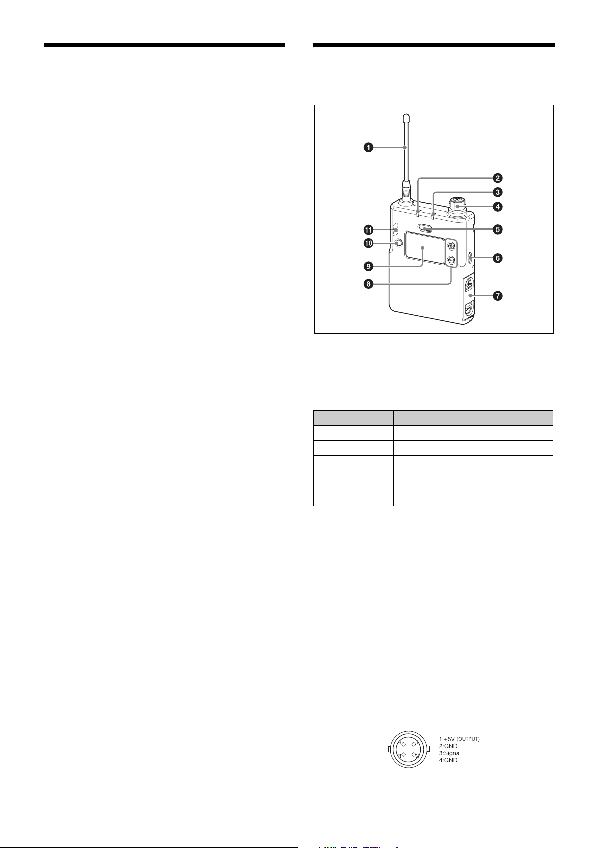
Parts Identification
a Antenna
Infrared communication function
When operating in conjunction with UWP-D series
receivers, the frequency and compander mode settings
configured on the receiver can be received via the infrared
communication function, allowing you to complete
channel configurations quickly.
Flexible power supply options
The unit supports three types of batteries; alkaline, nickel
metal hydride, and lithium. Power can also be supplied
via USB.
When using nickel metal hydride batteries, you can
charge the batteries while they are inside the unit by using
a commercially available USB portable power supply.
b POWER indicator
Displays the battery level and charging status.
Indicator display Status
On (green) Sufficient battery level
Flashing (green) Battery is getting low
On (orange) Charging (when nickel metal hydride
rechargeable batteries are inserted
and power is turned off)
Off Power is off or charging is complete
c AUDIO (audio input level) indicator
Turns on or off according to the audio input level as
follows.
On (red): Audio input level is too high. If the sound is
distorted, adjust the attenuation level to decrease the
audio input level (page 11).
On (green): Audio input level is appropriate.
Off: There is no audio input or the input level is too low.
Flashing (orange): Audio is muted (i.e., disabled).
d Audio input connector (SMC9-4S type
(female))
Connect to Sony ECM-77BC and ECM-44BC lavalier
microphones. You can also connect other microphone
types by using EC-1.5CF microphone cable (not
supplied).
3
Note
When the audio input level is set to MIC, a voltage for the
lavalier microphone power supply is applied to the audio
input connector. When connecting equipment other than
lavalier microphones, always use an EC-1.5CF
microphone cable (not supplied).
e POWER/MUTING button
Turns the power on/off. You also use this button to turn
the muting function on/off.
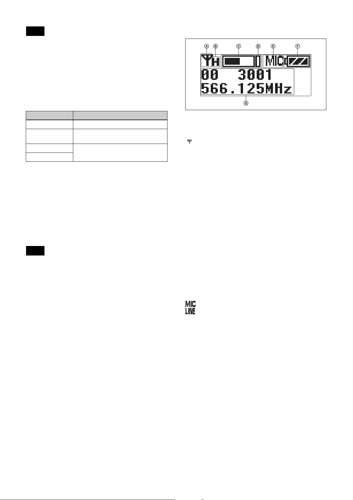
i Display section
Function Operation
Supply ON Press button for 1 second or longer
Supply OFF Press button until the indicator turns
off
Muting ON Press button
Muting OFF
f USB connector (Micro B type)
Connect to a commercially available USB portable power
supply.
When a USB portable power supply is connected while
the power is turned on, the unit automatically operates
with power supplied by the USB portable power supply.
When a USB portable power supply is connected while
nickel metal hydride batteries are inserted and the power
is turned off, the batteries are charged by the USB
portable power supply.
Note
Alkaline batteries and lithium batteries cannot be
recharged.
g Battery compartment
Accepts two AA batteries (alkaline, nickel metal hydride,
or lithium batteries).
For details on how to insert batteries, see “Power
Supply” (page 5).
h + or – button
Selects functions or values shown on the display.
A RF transmission indicator
Displays the current transmission status.
: Transmitting
– : Transmission stopped
B RF transmission power indicator
Indicates the current transmission power setting. You can
change the setting with the RF transmission power setting
function.
For details on the RF transmission power setting
function, see “Setting the transmit output level (RF
POWER)” (page 11).
C Audio input level meter
Displays the audio input level.
D Peak indicator
Lights up when the signal is 3 dB below the level at which
distortion begins as a warning of excessive input level.
E Input level indicator
Displays the input level status.
: Microphone input
: Line input
F Battery level indicator
Displays the battery level. Displays “EXT” when power
is supplied from the USB connector.
For details, see “Battery level indicator” (page 6).
G Menu display section
Displays various functions. Press the + or – button to
switch functions.
For details, see “Configuration Menu” (page 11).
j SET button
Adjusts displayed function settings and applies the
displayed value.
Holding down the SET button while turning on the power
turns the transmitter on without transmitting a signal
(transmission stopped mode).
4
k Infrared detector
Receives the frequency and compander mode set on the
receiver.
Power Supply
The unit operates using power supplied from two AA
batteries (alkaline, nickel metal hydride, or lithium
batteries) or from a supply connected to the USB
connector. If power is supplied simultaneously from
batteries and from a supply connected to the USB
connector, power from the USB connector has
precedence. For details about inserting batteries and
displaying the battery level, or supplying power from a
supply connected to the USB connector, see the following
sections.
Note
The use of manganese batteries will result in poor
performance. Do not use manganese batteries.
Inserting the Batteries
Notes
• Always use sets of the same type of battery. Do not use
batteries of different types or batteries with different
charge level together.
• Replacing the batteries during operation may generate
a large noise. Be sure to turn off the unit before
replacing the batteries.
1
Press and hold the POWER/MUTING button to turn
the power off.
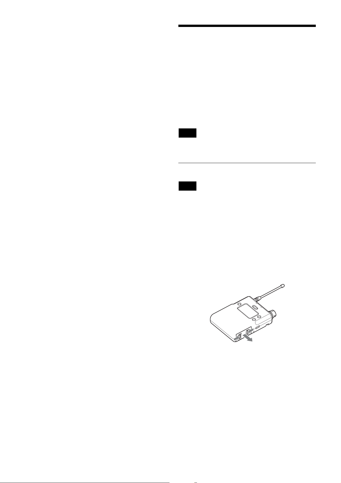
2
Slide the two catches inward (as indicated) and pull
the battery compartment out.
5
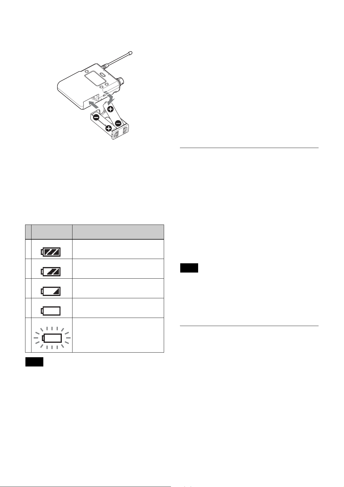
3
Insert two new AA batteries into the battery
compartment with 3 and # polarities in the correct
orientation, and close the compartment.
For details on the BATTERY function setting, see “Setting
the battery type (BATTERY)” (page 12).
Battery precautions
Batteries may leak or explode if mistreated. Be sure to
follow these instructions.
• Insert batteries in the correct 3 and # polarity
orientation.
• Always replace the two batteries together with new
ones.
• Do not use different types of batteries or old and new
ones together.
• Dry cells are not rechargeable.
• When not using the device for a long period of time,
remove the batteries. If the batteries leak for any reason,
contact your Sony service representative.
Make sure that the battery compartment is locked
securely.
Battery level indicator
Press and hold the POWER button for 1 second or longer
to display the battery level on the display.
Immediately replace both batteries with new batteries if
the indicator starts flashing (indication 5 below). If using
new alkaline batteries, use after checking the
recommended time limits.
Battery level
indicator
1Lights Good
2 Lights Less than 70% charge remaining
3 Lights Less than 40% charge remaining
4 Lights Less than 20% charge remaining
5 Flashes Almost empty
Battery status
Supplying Power from a USB
Connector
The unit can operate from a commercially available USBoutput type AC adapter or portable power supply
connected to the USB connector.
When supplying power using a USB-output type AC
adapter or portable power supply, use a unit that satisfies
the following conditions.
• Output connector: USB micro B type
• Rated voltage: 5 V
• Output current: 200 mA or higher
Displays “EXT” when power is supplied from the USB
connector.
Note
Noise may occur in the audio depending on the AC
adapter or portable power supply that is connected. In
such cases, you can reduce the noise by distancing the
unit or lavalier microphone from the AC adapter or
portable power supply or otherwise altering their
positions.
Notes
• When BATTERY is set to TYPE1, the battery level is
indicated based on the use of new LR6 (size AA) Sony
alkaline batteries. The battery level may not be
displayed correctly when different kinds of batteries,
different brand of batteries, or old batteries are used. If
using batteries other than size AA alkaline batteries,
select the battery type using the BATTERY function.
• If you plan to use the transmitter continuously for a long
period of time, it is recommended that you replace the
batteries with brand new ones.
Charging Nickel Metal Hydride
Batteries
You can charge nickel metal hydride batteries inserted in
the unit.
When charging nickel metal hydride batteries, turn the
power off and connect a commercially available USBoutput type AC adapter or portable power supply to the
USB connector.
The POWER indicator is lit orange while charging
batteries. When charging is finished, the POWER
indicator goes off.
When charging batteries using a USB-output type AC
adapter or portable power supply, use a unit that satisfies
the following conditions.
• Output connector: USB micro B type
• Rated voltage: 5 V
6

• Output current: 1 A or higher
Notes
• Charging may not be supported, depending on the
connected AC adapter, portable power supply, or
computer port.
• Nickel metal hydride batteries are not charged while the
transmitter or receiver is turned on.
Preparation
Connecting a Lavalier Microphone
Connect a Sony ECM-77BC or ECM-44BC lavalier
microphone to the unit.
Microphone
For a secure connection, turn to lock the connector.
Note
Be sure to attach or remove the microphone after turning
off the transmitter.
Attaching a Belt Clip
Insert one end of the belt
clip into one of two holes
on either side of the
transmitter, and then
insert the other end into
the hole on the other side.
7

To remove a belt clip
Insert a pointed object, such as
a ball-point pen, between the
belt clip and the transmitter,
and pry the end of the belt clip
from the hole on the side of the
transmitter.
Settings
Setting the Transmit Channel
For details about the channel groups and channels that can
be selected, refer to the “Frequency List” on the
CD-ROM.
Note
To prevent interference and noise, beware of the
following.
• Do not use multiple transmitters that have been set to
the same channel at the same time.
• When using two or more channels at the same time,
always configure different channels within the same
group.
• Keep all transmitters and receivers at least 3 m away
from each other.
1
Press and hold the SET button and press the POWER/
MUTING button to turn the power on.
2
Use the + or – button to display the GP/CH menu.
3
Press and hold the SET button for 1 second or longer.
Press and hold until the channel group display starts
flashing.
4
Use the + or – button to select the desired group
name, then press the SET button.
The channel group is set, and the channel number
display starts flashing.
5
Use the + or – button to select the desired channel
number, then press the SET button.
The displays stops flashing and the desired channel is
set.
8

6
Press and hold the POWER/MUTING button to turn
the power off, then press and hold the POWER/
MUTING button again to turn the power on.
Signal transmission starts.
Notes
• If there is no user input within 10 seconds after the
channel group display or channel number display starts
flashing, the displayed setting that is flashing is saved.
The same applies when setting other parameters.
• The frequency indicator changes in response to the
channel number.
• Do not remove the batteries while making settings. If
they are removed, re-insert them and repeat the
procedure from the beginning.
• Make sure that the same channel is set on transmitters
and receivers within the same system.
Setting the Compander Mode
Depending on the receiver being used in conjunction with
the unit, changing the compander mode may be
necessary.
Notes
Note
Audio will not be output if the combination of receivers
and compander mode settings are not correct.
Receiver Compander mode on
unit
UWP-D UWP WL800
UWP-D
series
(URX-P03,
URX-S03D)
UWP series (URX-P2, URX-M2) No Yes No
WRR series (WRR-855S,
WRR-862, etc.)
Compander mode:
UWP-D
Compander mode:
UWP
Compander mode:
WL800
Ye s N o N o
No Yes No
No No Yes
No No Yes
Using the Infrared Communication
Function
When operating in conjunction with UWP-D series
receivers, the frequency and compander mode settings
configured on the receiver can be sent and applied to the
unit using the infrared communication function.
• When operating in conjunction with UWP-D series
receivers, set the receivers to the same compander
mode.
• No audio will be output if the tone signal frequency is
different due to inconsistencies in compander mode
settings configured on the devices being used together.
• The compander mode can be configured when the menu
display is set to extended mode (page 10).
1
Use the + or – button to display the COMPANDER
menu.
2
Press and hold the SET button for 1 second or longer.
The selected item starts flashing.
3
Use the + or – button to select the compander mode,
then press the SET button.
The selected compander mode is configured.
UWP-D: Select this when operating in conjunction
with Sony UWP-D series receivers.
UWP: Select this when operating in conjunction with
Sony UWP series receivers.
WL800: Select this when operating in conjunction
with Sony WRR series receivers.
Note
This function cannot be used when operating in
conjunction with UWP or WRT series transmitters.
For details on the infrared communication function, refer
to the operating instructions supplied with the UWP-D
series receiver.
Receiver and compander mode
combinations
Configure the appropriate compander mode based on the
receivers being used.
9

Menu Displays and Detailed Settings
Menu Structure and Operation
• COMPANDER (compander mode) setting
• PWR LOCK (POWER button lock) function
• MUTING (muting function) setting
• PHASE (phase switching) setting
• BATTERY (battery type) setting
• CONTRAST (display text contrast) setting
• RESET (factory default setting) function
• VERSION (software version) display
There are three menu display modes that can be selected
according to the application.
Simple mode
This mode displays only the required settings for
transmitting audio.
You can enable simple mode by setting MENU MODE
(menu display mode) to SIMPLE.
Configuration menus
• GP/CH (group/channel) select
• BAND (frequency band) select (Not available on
Japanese and Korean models)
• RF POWER (RF transmit output level) select
• ATT (attenuator) setting
• LCF (low-cut filter) setting
• IN LEVEL (audio input level) select
• TIME (accumulated running time) display
• MENU MODE (menu display mode) setting
Note
The following configuration menus cannot be modified
during transmission. Set these menus in transmission
stopped mode.
• GP/CH (group/channel) select
The following configuration menus do not appear and
cannot be modified during transmission. Set these menus
in transmission stopped mode.
• BAND (frequency band) select (Not available on
Japanese and Korean models)
• RF POWER (RF transmit output level) select
• RESET (factory default setting) function
Transmission stopped mode
This mode allows settings to be modified when RF
transmission has stopped.
Use this mode to make settings without risk of
interrupting other wireless traffic when setting channels
and other settings.
With the power off, press and hold the SET button and
press the POWER/MUTING button for at least 1 second
to turn the power on and to display the transmission
stopped mode menu.
The following configuration menus can only be modified
in transmission stopped mode.
• GP/CH (group/channel) select
• BAND (frequency band) select (Not available on
Japanese and Korean models)
• RF POWER (RF transmit output level) select
• RESET (factory default setting) function
Extended mode
This mode displays all configuration menus.
You can enable extended mode by setting MENU MODE
(menu display mode) to ADVANCED.
Note
The existing settings configured in extended mode are
active even when using simple mode.
Configuration menus
• GP/CH (group/channel) select
• BAND (frequency band) select (Not available on
Japanese and Korean models)
• RF POWER (RF transmit output level) select
• ATT (attenuator) setting
• LCF (low-cut filter) setting
• IN LEVEL (audio input level) select
• TIME (accumulated running time) display
• MENU MODE (menu display mode) setting
Basic menu operation
The basic menu operation is the same in simple mode,
extended mode, and transmission stopped mode.
Function name
Setting
1
Press the + or – button to display the function to be
set.
10

2
Press and hold the SET button until the setting starts
flashing.
3
Press the + or – button to change the setting.
4
Press the SET button to apply the setting.
Adjusting the audio input attenuation
level (ATT)
Set the audio input attenuation level in 3 dB increments to
reduce noise distortion.
The factory default setting is 9 dB.
Note
If no operation is performed for 5 seconds, the backlight
will turn off. Pressing any button will turn the backlight
on again.
Configuration Menu
This section describes each function and configurable
items.
Underlined entries indicate factory default settings.
Selecting group/channel (GP/CH)
The factory default setting varies depending on the
model.
For details, see “Setting the Transmit Channel” (page 8).
Note
This function can be modified in transmission stopped
mode only.
Notes
• “---” is displayed if IN LEVEL is set to LINE, and the
attenuation level cannot be modified (fixed at 0 dB).
• If the attenuation level is set too high, the noise level
may increase. Set the level as close as possible to 0 dB
if using a lavalier microphone attached to your torso.
Setting the low-cut filter (LCF)
Set the low-cut filter to reduce noise caused by wind.
You can set the cutoff frequency to OFF/LOW/MID/
HIGH.
OFF
: No filtering
LOW: 100 Hz cutoff frequency
MID: 150 Hz cutoff frequency
HIGH: 200 Hz cutoff frequency
Switching the audio input level (IN LEVEL)
Set the input level according to the audio input device.
You can switch between MIC and LINE. The factory
default setting is MIC.
Note
Selecting the frequency band (BAND)
Select the transmit frequency band.
Notes
• This function can be modified in transmission stopped
mode only.
• This menu is not available on Japanese and Korean
models. On these models, the frequency band cannot be
selected.
For details about the groups and channels in each
frequency band, refer to the “Frequency List” on the
CD-ROM.
Setting the transmit output level (RF
POWER)
Set the transmitted RF power to HIGH or LOW. The
transmit power level varies depending on the model.
Note
This function can be modified in transmission stopped
mode only.
Do not switch this function to “MIC” when the audio
input source is an audio mixer or other line level device.
If an excessive audio level is input, it may cause noise
distortion or damage the playback/recording equipment.
Displaying the accumulated running time
(TIME)
Display the accumulated running time of the transmitter
as a guide to total usage time.
The factory default setting is 00:00. Up to 99:99 can be
displayed.
To reset the time display
1
Press and hold the SET button until the time display
starts flashing.
2
Press the – button to display “00:00 CLR” and press
the SET button.
Pressing the + button when “00:00 CLR” is displayed
causes the time display to start flashing. You can
press the SET button in this state to cancel the reset of
the accumulated running time.
Setting the menu display mode (MENU
MODE)
Set the menu display mode.
SIMPLE
11
: Displays only the required settings.

ADVANCED: Displays all settings.
Setting the compander mode
(COMPANDER)
Set the operating mode of the compander.
UWP-D
combination with UWP-D series devices.
UWP: Mode supported in combination with Sony UWPseries receivers.
WL800: Mode supported in combination with Sony 800series receivers.
Notes
• This function is displayed in extended mode only.
• No audio is output if the tone signal frequency is
: High speech quality mode supported in
different due to the use of a combination of devices with
different compander mode settings.
ENABLE
the output.
DISABLE: The output is not muted even when the
POWER/MUTING button is pressed.
Notes
• This function is displayed in extended mode only.
• In muting, the audio signal is not output but an RF
signal is still transmitted.
: Pressing the POWER/MUTING button mutes
Switching the phase of the microphone
(PHASE)
Depending on the model of the connected microphone,
change the phase setting.
NORMAL
INVERT: Reverses the phase within the transmitter. Set
to INVERT when an EC-1.5CF is connected.
: Phase is not reversed.
Locking the POWER/MUTING button
(PWR LOCK)
Lock the POWER/MUTING button to prevent the power
being turned off inadvertently during transmission.
UNLOCK
to turn the power on/off.
LOCK: The power does not turn off, even after pressing
the POWER/MUTING button.
To release the lock state
To release the lock state, either set the PWR LOCK menu
to UNLOCK or use the following procedure.
1
2
Notes
: Press and hold the POWER/MUTING button
When the button is in the LOCK state, press and hold
the POWER/MUTING button.
A prompt appears asking you whether to release the
lock state.
Use the + or – button to select YES, then press the
SET button.
The lock state is released.
Note
This function is displayed in extended mode only.
Setting the battery type (BATTERY)
Set the type of battery being used in order to provide a
more accurate battery level indication.
TYPE1
(size AA) batteries. Indicates the battery level based on
the characteristics of new Sony alkaline LR6 (size AA)
batteries.
TYPE2: Recommended setting when using rechargeable
nickel metal hydride batteries.
TYPE3: Recommended setting when using lithium
batteries.
Notes
• This function is displayed in extended mode only.
• The characteristics of batteries change according to
: Recommended setting when using alkaline LR6
battery type and environmental conditions. It is
recommended that you understand the characteristics of
batteries before using them.
• This function is displayed in extended mode only.
• The POWER/MUTING button lock state does not
change after switching to simple mode after setting the
button to LOCK in extended mode.
• If the batteries are removed and reinserted while the
POWER/MUTING button is set to LOCK, the power
will turn on automatically but the lock state of the
POWER/MUTING button does not change.
Muting the output (MUTING)
Pressing the POWER/MUTING button while
transmitting mutes the audio so that audio from the
receiver is not output.
Pressing the POWER/MUTING button again restores the
audio output.
Setting the display contrast (CONTRAST)
Adjust the contrast of text and icons on the display in the
range 1 to 10.
The configurable values are given below.
(Light) 1 2 3 4 5 6
Note
This function is displayed in extended mode only.
7 8 9 10 (Dark)
Restoring factory default settings
(RESET)
Restore all parameters to their factory default settings.
Press and hold the SET button. A prompt appears asking
you whether to restore factory default settings. Press the
12

+ or – button to select YES, then press the SET button.
The transmitter parameters are restored to their factory
default settings.
Error Messages
Notes
• This function can be used in transmission stopped mode
only.
• After a reset, the audio input level is also restored to its
factory default setting. Note that this may cause the
volume on devices connected to the receiver and in
headphones to suddenly change.
Displaying the software version
(VERSION)
Display the software version of the transmitter.
Note
This function is displayed in extended mode only.
When a problem occurs, one of the following error
messages may appear on the display.
Message Meaning Solution
EEP
ERROR
PLL ERROR An error occurred in
An error has
occurred in the
backup memory
data.
the PLL synthesizer
circuit.
Contact your Sony
service representative.
Restart the unit. If the
message persists,
contact your Sony
service representative.
13

Troubleshooting
If you have any problem, use the following checklist before asking for repairs. If the problem persists, contact your Sony
service representative.
Symptom Cause Solution
The unit does not turn
on.
The unit does not turn
off.
The batteries become
drained quickly.
The channel cannot
be changed.
There is no sound. The channel setting on the transmitter is different
The sound is weak. The attenuation level on the transmitter is too high. The input level of the transmitter is low. Set the
The sound is
distorted.
There is sound
interruption or noise.
The 3 and # polarity orientation of the batteries is
incorrect.
The batteries are getting low. Replace the batteries with new ones.
The battery terminals are dirty. Clean the 3 and # terminals with a cotton swab.
The POWER/MUTING button is locked. Release the locked status in the PWR LOCK
The batteries are getting low. Replace the batteries with new ones.
Manganese batteries are being used. Use alkaline batteries. The battery life of a
The device is being used under cold conditions. The batteries drain quickly under cold conditions.
The unit is not in transmission stopped mode. Turn off the unit, and then turn it on again while
from that on the receiver.
The transmitter is not transmitting signals, or the
transmission output is weak.
The transmitter is set to line level input. Switch to microphone input.
The compander mode setting on the transmitter is
different from that on the receiver.
The transmitter is muted.
The volume on the amplifier or mixer is low. Adjust the volume to an appropriate level.
The transmitter is set to line level input. Switch to microphone input.
The compander mode setting on the transmitter is
different from that on the receiver.
The attenuation level on the transmitter is too low
or is set to 0.
The channel setting on the transmitter is different
from that on the receiver.
The compander mode setting on the transmitter is
different from that on the receiver.
The channel setting on the transmitter is different
from that on the receiver.
Two or more transmitters are set to the same
channel.
The transmitters are not set to the channels within
the same channel group.
Adjacent channels are being used. Use the channels separated by at least two
Insert the batteries with the correct polarity
orientation.
menu.
manganese battery is less than half that of an
alkaline battery.
holding down the SET button to switch to
transmission stopped mode.
Use the same channel setting on both the
transmitter and receiver.
Confirm that the transmitter is turned on.
Alternatively, reduce the distance between the
transmitter and receiver.
Use the same compander mode setting on both
the transmitter and receiver.
Press the POWER/MUTING button on the
transmitter to release the muted state.
attenuation of the transmitter to an appropriate
level.
Use the same compander mode setting on both
the transmitter and receiver.
The input level is extremely high. Set the
attenuation on the transmitter so that the audio is
not distorted.
Use the same channel setting on both the
transmitter and receiver.
Use the same compander mode setting on both
the transmitter and receiver.
Use the same channel setting on both the
transmitter and receiver.
Two or more transmitters cannot be used on the
same channel. Refer to the frequency list stored
on the supplied CD-ROM, and reconfigure the
channel on each transmitter.
The channel plan is set so that no signal
interference occurs when two or more transmitters
are used simultaneously. Set each transmitter to a
different channel within the same channel group.
channels (250 kHz).
14

Symptom Cause Solution
The transmitter
channel cannot be set
with infrared
transmission.
The infrared receptor on the transmitter is too far
from the infrared transmission port on the receiver.
Interference from infrared communications
between other devices or from direct sunlight is
present.
Reduce the distance between the infrared receptor
on the transmitter and the infrared transmission
port on the receiver to within about 20 cm (8 in.).
The transmitting distance is reduced when
interference from strong sunlight, for example, is
present. Place the transmitter and receiver as
close to each other as possible.
15

Important Notes on Use
Specifications
Usage and Storage
• Operating the UWP-D series devices near electrical
equipment (motors, transformers, or dimmers) may
cause interference due to electromagnetic induction.
Keep the devices as far from such equipment as
possible.
• The presence of lighting equipment may produce
electrical interference over a wide frequency range. In
this case, interference may fluctuate with the position of
the receiver antenna and position of the transmitter.
Position the devices so that interference is minimized.
• To avoid degradation of the signal to noise ratio, do not
use UWP-D devices in noisy places or in locations
subject to vibration, such as the following:
– Near electrical equipment, such as motors,
transformers, or dimmers
– Near air conditioning equipment or places subject to
direct air flow from an air conditioner
– Near PA (public address) loudspeakers
– Near equipment that might knock against the receiver
Keep devices as far from such equipment as possible or
use buffering material.
Cleaning
Clean the surface and the connectors of devices with a
dry, soft cloth. Never use thinners, benzene, alcohol, or
any other chemicals, since these may mar the finish.
To prevent electromagnetic interference
Some channels may be unable to be used due to noise
generated due to the effects of external noise and/or
radio interference. In this case, it is recommended to
stop transmitting (turn the power off) or change to
another frequency (change channel).
To prevent electromagnetic interference from
portable communication devices
The use of portable telephones and other
communication devices near the devices may result in
malfunction and interference with audio signals. It is
recommended that portable communication equipment
near the devices be turned off.
Antenna 1/4 λ wavelength wire antenna
Audio input connector
SMC9-4S (female)
Reference audio input level
–60 dBV (MIC input, 0 dB attenuation)
Frequency response
40 Hz to 18 kHz
Attenuation 0 dB to 27 dB (3 dB steps)
Indicators AUDIO, POWER/MUTING
Oscillator type Crystal-controlled PLL synthesizer
Carrier frequencies
Models available in USA:
470 MHz to 542 MHz (UC14 model),
566 MHz to 608 MHz and
614 MHz to 638 MHz (UC30 model),
638 MHz to 698 MHz (UC42 model)
Models available in Europe:
470 MHz to 542 MHz (CE21 model),
566 MHz to 630 MHz (CE33 model),
638 MHz to 694 MHz (CE42 model)
Model available in China:
710 MHz to 782 MHz (CN38 model)
Model available in Korea:
925 MHz to 937.5 MHz (KR Model)
Model available in Thailand:
794 MHz to 806 MHz (E model)
RF output level 30 mW/5 mW selectable (for model
available in USA, Europe, and
China)
10 mW/2 mW selectable (for model
available in Thailand and Korea)
Preemphasis 50 μs
Reference deviation
±5 kHz (–60 dBV, 1 kHz input)
Distortion 0.9% or less (–60 dBV, 1 kHz input)
Signal-to-noise-ratio
60 dB or more
Voice delay 0.35 ms
Tone signal frequency
In UWP-D compander mode:
32.382 kHz
In UWP compander mode: 32 kHz
In WL800 compander mode:
32.768 kHz
Supply voltage 3.0 V DC (two LR6/AA size alkaline
batteries)
5.0 V DC (supplied from USB
connector)
Battery life (measured with two Sony LR6/AA size
alkaline batteries at 25 °C (77 °F))
Approx. 8 hours with output power of
30 mW (for model available in USA,
Europe, and China)
Approx. 10 hours with output power of
10 mW (for model available in
Thailand and Korea)
16

Operating temperature
0 °C to 50 °C (32 °F to 122 °F)
0 °C to 35 °C (32 °F to 95 °F) when
charging
Storage temperature
–20 °C to +55 °C (–4 °F to +131 °F)
Dimensions
63 × 92.6 × 20 mm (2
13
/16in.) (width / height / depth)
1
/2 × 3 3/4 ×
(excluding antenna)
Mass Approx. 105 g (3.7 oz.)
(excluding batteries)
Supplied accessories
Belt clip (1)
Battery case (1) (Chinese model only)
Before Use (1)
CD-ROM (1)
Warranty card (1)
Design and specifications are subject to change without
notice.
Notes
• Always verify that the unit is operating properly
before use. SONY WILL NOT BE LIABLE FOR
DAMAGES OF ANY KIND INCLUDING, BUT
NOT LIMITED TO, COMPENSATION OR
REIMBURSEMENT ON ACCOUNT OF THE
LOSS OF PRESENT OR PROSPECTIVE PROFITS
DUE TO FAILURE OF THIS UNIT, EITHER
DURING THE WARRANTY PERIOD OR AFTER
EXPIRATION OF THE WARRANTY, OR FOR
ANY OTHER REASON WHATSOEVER.
• SONY WILL NOT BE LIABLE FOR CLAIMS OF
ANY KIND MADE BY USERS OF THIS UNIT OR
MADE BY THIRD PARTIES.
• SONY WILL NOT BE LIABLE FOR THE
TERMINATION OR DISCONTINUATION OF
ANY SERVICES RELATED TO THIS UNIT THAT
MAY RESULT DUE TO CIRCUMSTANCES OF
ANY KIND.
17

Sony Corporation
 Loading...