

Sony UP-890MD, UP-880, UP-890CE User Manual [en, de, fr, it]
Video Graphic
Printer
3-798-008-15 (1)
Instructions for Use Page 2
Before operating this unit, please read this manual thoroughly
and retain it for future reference.
Mode d’emploi Page 24
Avant la mise en service de cet appareil, prière de lire
attentivement ce mode d’emploi que l’on conservera pour toute
référence ultérieure.
Gebrauchsanweisung Seite 46
Bevor Sie dieses Gerät verwenden, lesen Sie diese Anleitung
bitte sorgfältig durch, und bewahren Sie sie für später zum
Nachschlagen auf.
Manual de instrucciones página 68
Antes de utilizar la unidad, lea este manual detenidamente y
consérvelo para futuras referencias.
Istruzioni per l’uso pagina 90
Prima di usare l’apparecchio, leggete con attenzione questo
manuale e conservatelo per riferimenti futuri.
UP-880/890CE/890MD
1994 by Sony Corporation

English
Owner’ s Record
The model and serial numbers are located at the rear.
Record these number in the space provided below.
Refer to these numbers whenever you call upon your
Sony dealer regarding this product.
Model No.
Serial No.
W ARNING
To prevent fire or shock hazard, do not expose the unit
to rain or moisture.
To avoid electrical shock, do not open the cabinet. Refer
servicing to qualified personnel only.
For UP-890CE/890MD
Symbols on the products
This symbol indicates the equipotential
terminal which brings the various parts of a
system to the same potential.
3.The leakage current could increase when connected to
other equipment.
4.This equipment generates, uses, and can radiate
frequency energy. If it is not installed and used in
accordance with the instruction manual, it may cause
interference to other equipment. If this unit causes
interference (which can be determined by unplugging
the power cord from the unit), try these measures:
Relocate the unit with respect to the susceptible
equipment. Plug this unit and the susceptible
equipment into different branch circuit. Consult your
dealer.
For the customers in the U.S.A.
This equipment has been tested and found to comply
with the limits for a Class A digital device, pursuant to
Part 15 of the FCC Rules. These limits are designed to
provide reasonable protection against harmful
interference when the equipment is operated in a
commercial environment.
This equipment generates, uses, and can radiate radio
frequency energy and, if not installed and used in
accordance with the instruction manual, may cause
harmful interference to radio communications. Operation
of this equipment in a residential area is likely to cause
harmful interference in which case the user will be
required to correct the interference at his own expense.
For UP-890MD
This symbol is intended to alert the
user to the presence of uninsulated
"dangerous voltage" within the
product's enclosure that may be of
sufficient magnitude to constitute a risk
of electric shock to persons.
This symbol is intended to alert the
user to the presence of important
operating and maintenance (servicing)
instructions in the literature
accompanying the appliance.
Important safequards notices for use in the
medical environments
1.All the equipments connected to this unit shall be
certified according to Standard IEC601-1, IEC950,
IEC65 or other IEC/ISO Standards applicable to the
equipments.
2.When this unit is used together with other equipment in
the patient area*, the equipment shall be either
powered by an isolation transformer or connected via
an additional protective earth terminal to system
ground unless it is certified according to Standard
IEC601-1.
* Patient Area
R1.5m
You are cautioned that any changes or modifications not
expressly approved in this manual could void your
authority to operate this equipment.
The shielded interface cable recommended in this
manual must be used with this equipment in order to
comply with the limits for a digital device pursuant to
Subpart B of Part 15 of FCC Rules.
For the customers in the United Kingdom
WARNING
THIS APPARATUS MUST BE EARTHED
IMPORTANT
The wires in this mains lead are coloured in accordance
with the following code:
Green-and-yellow: Earth
Blue: Neutral
Brown: Live
As the colours of the wires in the mains lead of this
apparatus may not correspond with the coloured
markings identifying the terminals in your plug proceed
as follows:
The wire which is coloured green-and-yellow must be
connected to the terminal in the plug which is marked by
the letter E or by the safety earth symbol Y or coloured
green or green-and-yellow.
The wire which is coloured blue must be connected to the
terminal which is marked with the letter N or coloured
black.
The wire which is coloured brown must be connected to
the terminal which is marked with the letter L or coloured
red.
2

Table of Contents
Introduction
Preparation
Operation
Others
Overview 4
Connection 5
Before Printing 6
Setting the Type of Paper 6
Setting the DIP Switches 7
Loading Paper 10
Printing 12
Making Print-outs 12
Selecting the Printing Direction 13
Selecting the Printing Size 13
Adjusting the Contrast and Brightness 15
Precautions 16
Maintenance 17
On the Type of Paper 19
Specifications 20
Troubleshooting 21
Location and Function of Parts 22
Front 22
Back 23
3

Introduction
Overview
The UP-880/890CE/890MD is a black and white video graphic printer that can be
used to print images displayed on video monitor.
Clear, consistent print quality
• High definition, 10.2 dots/mm printing using a thermal head with high-speed
drive IC.
• 256 gradations of black and white.
Fast printing
• You can make a single print-out in about 3.9 seconds in STD and NORM mode.
• You can make a maximum of 11 copies of the same image continuously.
Two way printing direction and five printing sizes selectable
• The printing direction selector on the front panel enables you to print in vertical
and horizontal directions.
• The printing size control on the front panel enables you to select five kinds of
printing size.
DIP switches to optimize the printer
• You can make print-outs starting either from the bottom or top of the image by
setting the DIRECTION DIP switch.
• You can set the print-out aspect ratio to 4:3 or 1:1 by setting the ASPECT DIP
switch.
• You can set the range to be printed by setting the SCAN DIP switch.
• You can save your paper by setting the POSTFEED DIP switch (paper saving
function).
Automatic video signal discrimination
The type of input signal, black and white (EIA or CCIR) or input color (NTSC or
PAL), is automatically discriminated and printed in same duration and size.
Alarm buzzer
The alarm buzzer prevents you from making any misoperation.
Easy and quick paper loading
You can load paper just by opening the paper lid with the OPEN/CLOSE button
and placing the paper roll.
4
Introduction
Preparation
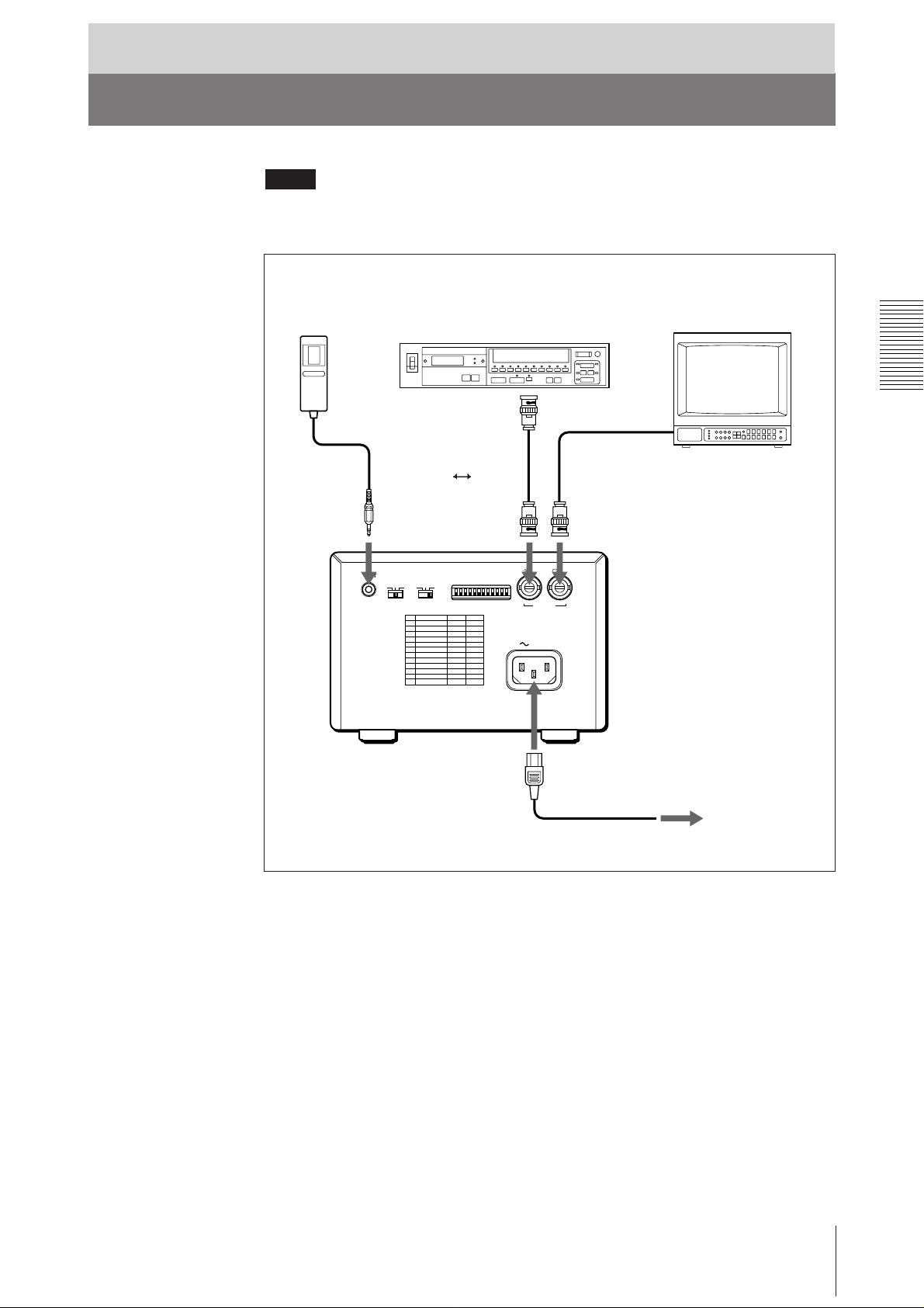
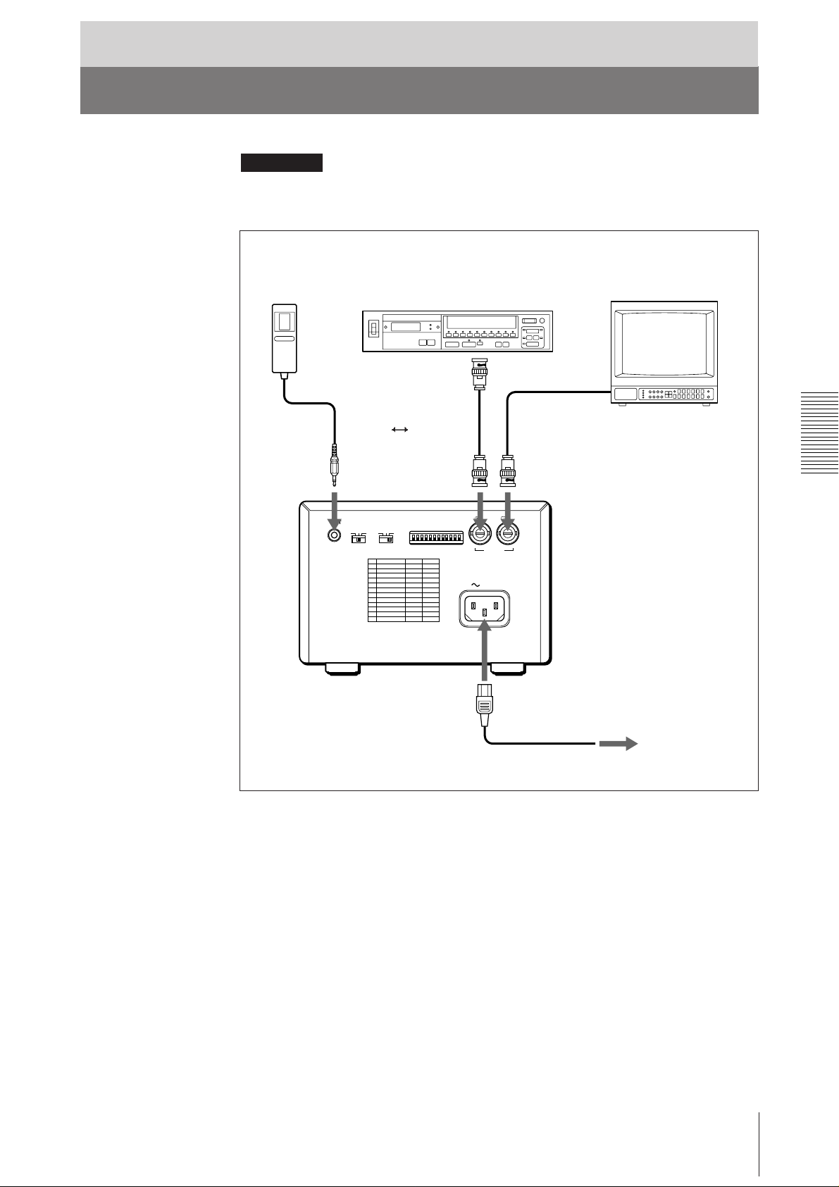
Connection
Notes
• Turn off the power to each device before making connection.
• Connect the AC power cord last.
RM-91 remote
commander*
to REMOTE
Video equipment
to video output
connector
Supplied coaxial
connecting cable
(BNC ˜ BNC)
REMOTE GAMMA TYPE
PAPER
IIIIII IIIIV
to VIDEO IN
DIP SW
OFF
ON
Color/black and white
video monitor
Connecting cable
(not supplied)
to video input
connector
to VIDEO OUT
IN OUT
VIDEO
AC IN
to AC IN
to wall outlet
Supplied AC power cord
* The RM-91 remote commander is supplied with UP-890MD only.
Preparation
5
Before Printing
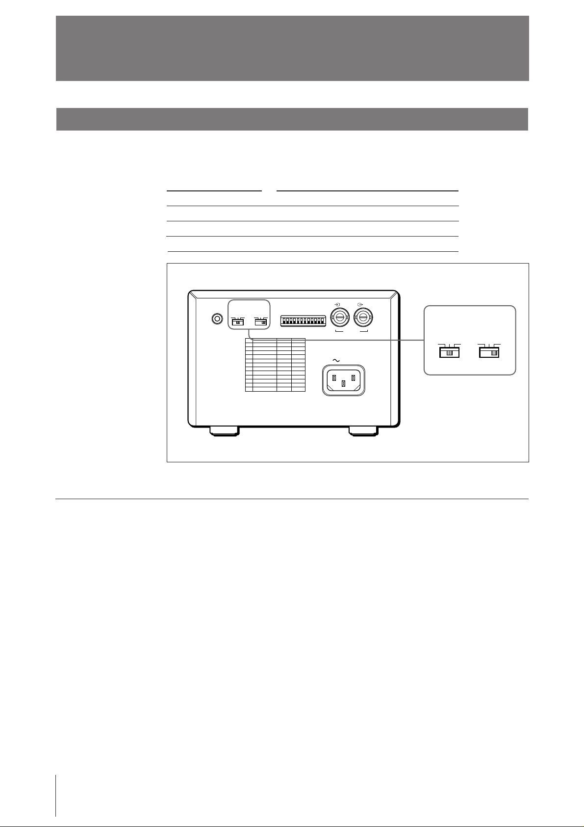
Setting the Type of Paper
Set the PAPER TYPE selector to the type of paper to be used.
The use of paper other than Sony may result in reduced printer performance and
poor print quality.
Type of paper
UPP-110S
UPP-110HD
UPP-110HA
REMOTE GAMMA TYPE
PAPER
IIIIII IIIIV
PAPER TYPE switch position
I (Normal)
II (High density)
IV (Enhanced)
DIP SW
OFF
ON
IN OUT
VIDEO
AC IN
GAMMA TYPE
IIIIII IIIIV
PAPER
When you use the UPP-110HA or UPP-110HD
When you set the PAPER TYPE selector to II or IV, set the density gradation with
the GAMMA selector.
I: Soft gradation
II: Standard
IV: Hard gradation
6
Preparation
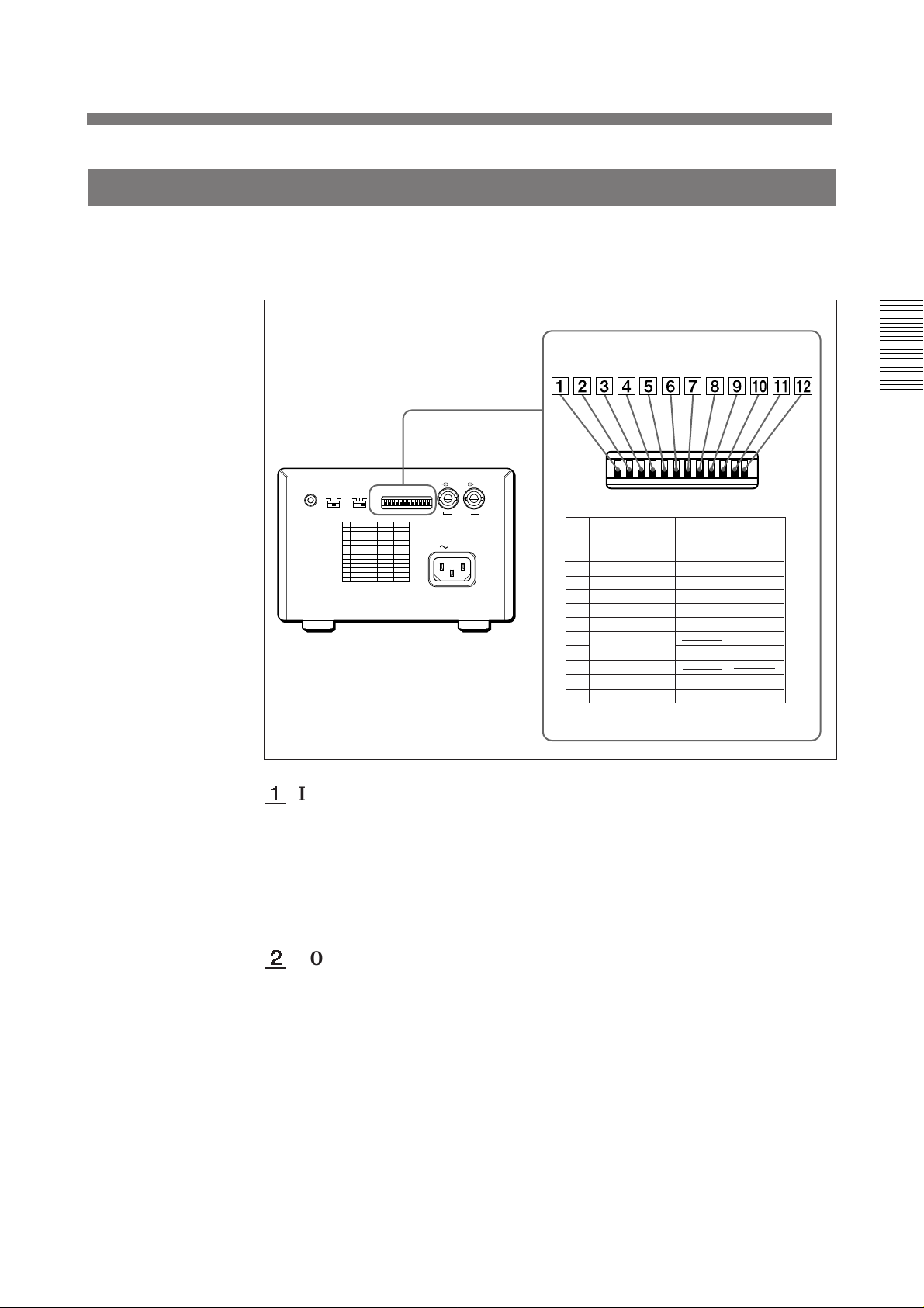
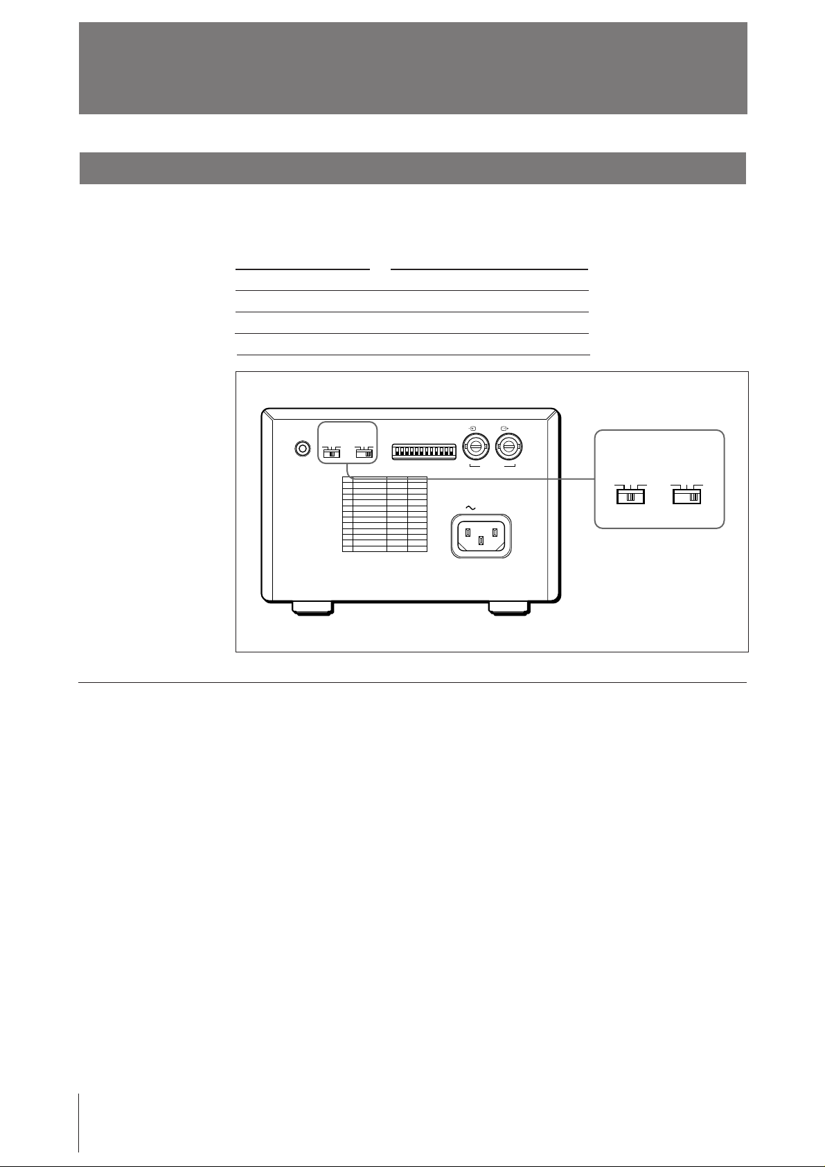
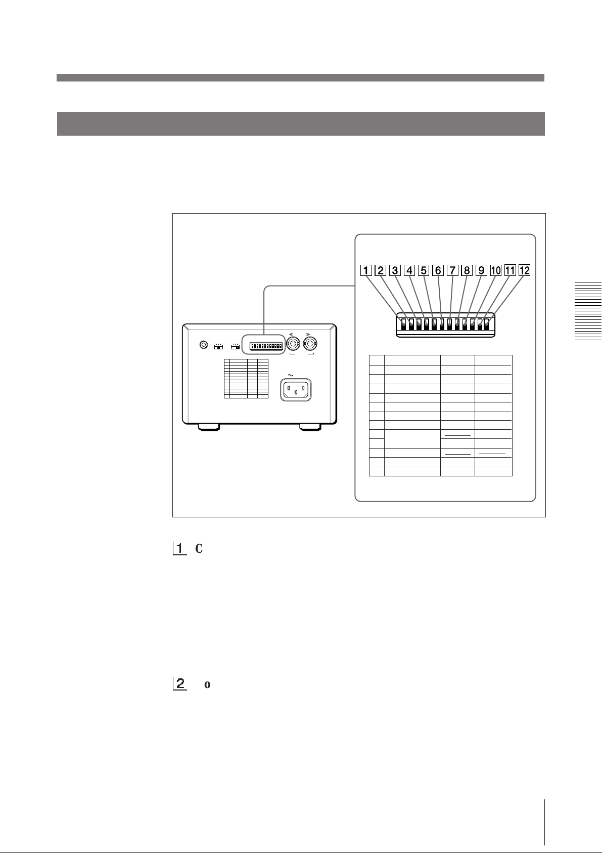
Setting the DIP Switches
Set the DIP switches according to the required print mode. Before setting the DIP
switches, turn the power off. Change the settings using a small pointed tool such as
a small screwdriver. The factory settings are as follows.
REMOTE GAMMA TYPE
PAPER
IIIIII IIIIV
DIP SW
OFF
ON
IN OUT
VIDEO
AC IN
DIP SW
OFF
ON
DIP SW FUNCTION TABLE
NO
FUNCTION
1
INTERRUPT
2
POSTFEED
3
ASPECT
4
MEMORY
5
IMAGE
6
MIRROR
7
DIRECTION
8
SCAN
9
10
RESERVED
11
INPUT
12
75
SW-ON
ON
ON
4:3
FRAME
POSI
NORM
NORM
WIDE 1
B&W
ON
SW-OFF
OFF
OFF
1:1
FIELD
NEGA
REV
REV
WIDE 2
NORM
COLOR
OFF
1
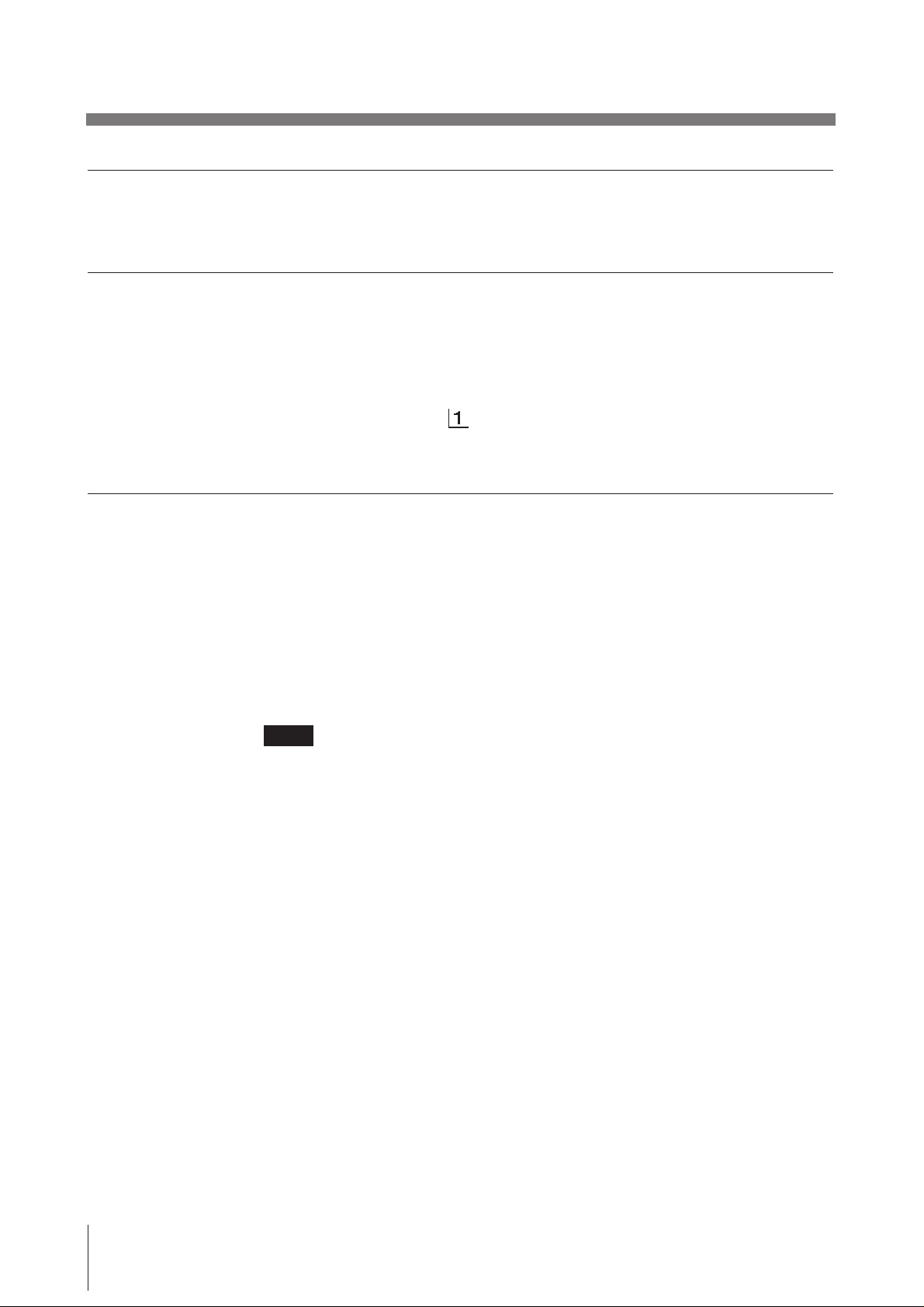
INTERRUPT ON/OFF switch
To interrupt the printing under way and print a new picture when you press
the PRINT button during printing, set this switch to ON.
To disregard that the PRINT button is pressed during printing and continue
the printing under way, set to OFF.
If you press the PRINT button during printing in OFF mode, the alarm buzzer
will sound.
2
POSTFEED ON/OFF switch
To feed out extra blank paper once a picture has been printed, set this switch
to ON.
To save paper by feeding only a short length of paper after printing a picture,
set to OFF. You can make more print-outs per roll of printing paper, but you
have to take out and cut the paper yourself.
Preparation
7
Before Printing (continued)
275
87654321
475
50
250
9
4
5
5
7
5
4
3
3
2
3
2
30
10
7
0
3
275
87654321
475
50
250
9
4
5
5
7
5
4
3
3
2
3
2
30
10
7
0
3
275
87654321
475
50
250
9
4
5
5
7
5
4
3
3
2
3
2
30
10
7
0
3
275
87654321
475
50
250
9
4
5
5
7
5
4
3
3
2
3
2
30
10
7
0
3
3
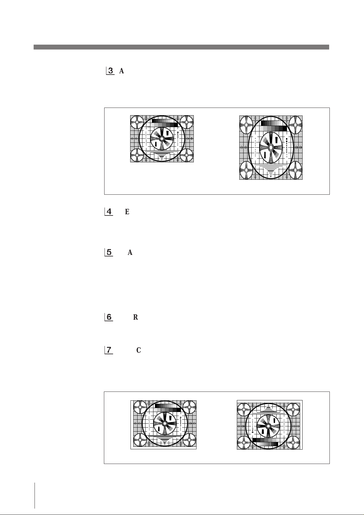
ASPECT 4:3/1:1 switch
Normally keep this switch set to 4:3. When the aspect ratio of the video
signal is 1:1, set to 1:1.
The print-out will be longer than a print-out made at 4:3.
1
2
3
3
5
2
3
30
4
3
3
4
1 357 7 531
4
3
3
4
30
3
2
5
3
3
2
1
4 : 3
5
2
3
1
3
2
3
30
4
3
3
4
4
3
3
4
30
3
2
5
3
3
2
1
1
2
3
3
5
2
3
30
4
3
3
4
1 357 7 531
4
3
3
4
30
3
2
5
3
3
2
1
5
3
1
4
3
3
4
4
3
3
4
5
3
1
1 : 1
4
MEMORY FRAME/FIELD switch
Normally keep this switch set to FRAME (ON). When printing fast-moving
pictures (such as a ball being thrown), the print-out may blur. If this happens,
set to FIELD. The print-out definition will be poorer but less blurred.
5
IMAGE POSI/NEGA switch
Normally keep this switch set to POSI (ON). To make negative print-outs, set
to NEGA (OFF).
Note
If you set the THRU/EE selector to the EE side, the unit prints positive
pictures irrespective of setting the IMAGE POSI/NEGA switch.
2
3
2
3
30
30
3
2
3
2
6
MIRROR NORM/REV switch
Normally keep this switch set to NORM (ON). To print the right and left
sides reversed, set to REV (OFF).
7
DIRECTION NORM/REV switch
Selects whether the top or bottom of the screen is to be printed first.
Normally keep this switch set to NORM (ON). Printing is done from the
bottom of the screen. To start printing from the top of the screen, set to REV
(OFF).
1
2
3
3
5
2
3
30
4
3
3
4
1 357 7 531
4
3
3
4
30
3
2
5
3
3
2
1
Preparation
8
NORM
5
2
3
1
3
2
3
30
4
3
3
4
4
3
3
4
30
3
2
5
3
3
2
1
1
2
3
3
5
2
3
30
4
3
3
4
4
3
3
4
30
3
2
3
1
3
2
5
1
2
3
3
5
2
3
30
4
3
3
4
1 357 7 531
4
3
3
4
30
3
2
5
3
3
2
1
REV
89
275
87654321
475
50
250
9
4
5
5
7
5
4
3
3
2
3
2
30
10
7
0
3
275
87654321
475
50
250
9
4
5
5
7
5
4
3
3
2
3
2
30
10
7
0
3
275
87654321
475
50
250
9
4
5
5
7
5
4
3
3
2
3
2
30
10
7
0
3
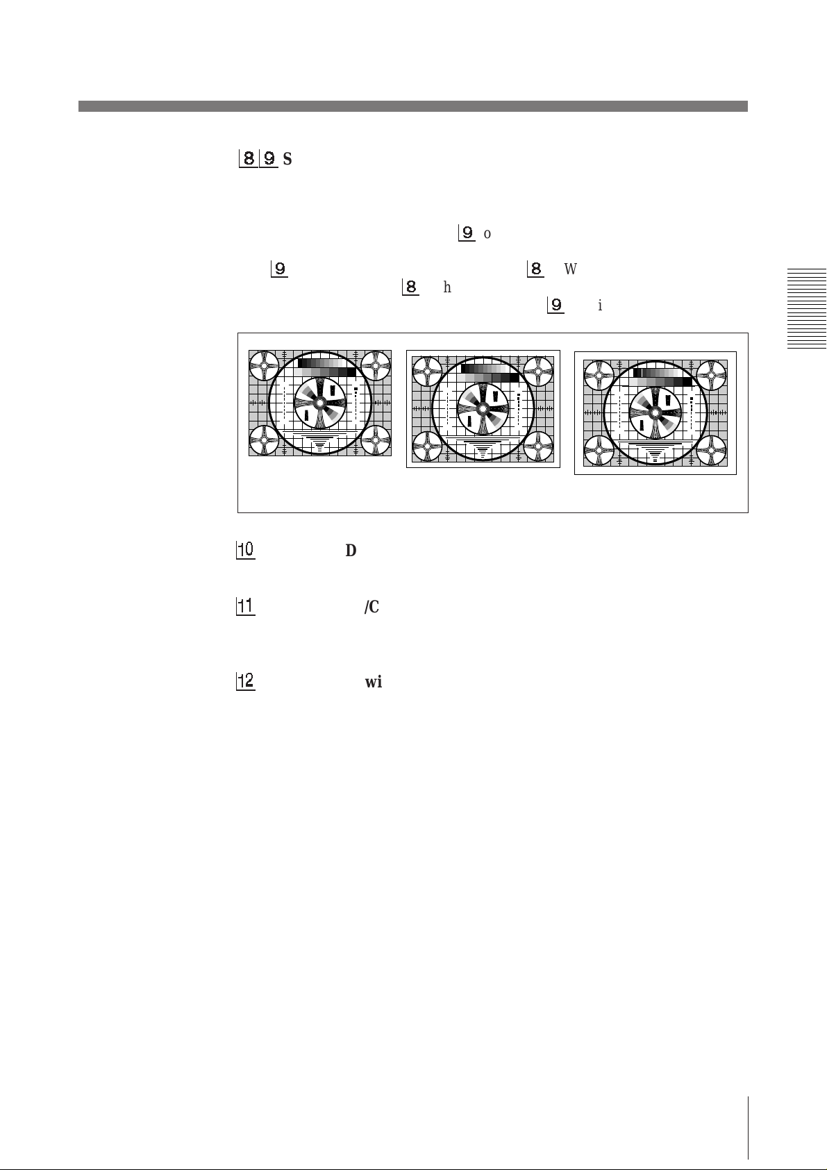
SCAN NORM/WIDE 1/WIDE 2 switch
Sets the print-out range. The print-out range is widened in the NORM, WIDE
1, and WIDE 2 order.
To print only the image displayed on the standard screen size of the video
monitor, set the SCAN switch 9 to NORM (OFF). To print when the signal
scans beyond the edge of the standard monitor screen, set the SCAN switch
9
to WIDE 1 (ON) or the SCAN switch 8 to WIDE 2 (OFF). When you
set the SCAN switch 8 to the WIDE 2 position, WIDE 2 is selected
regardless of the setting of the SCAN switch 9 position.
1
2
3
3
5
2
3
30
4
3
3
4
1 357 7 531
4
3
3
4
30
3
2
5
3
3
2
1
NORM
!º
RESERVED switch
5
2
3
1
3
2
3
30
4
3
3
4
4
3
3
4
30
3
2
5
3
3
2
1
1
2
3
3
5
2
3
30
4
3
3
4
1 357 7 531
4
3
3
4
30
3
2
5
3
3
2
1
WIDE 1
5
2
3
1
3
2
3
30
4
3
3
4
4
3
3
4
30
3
2
5
3
3
2
1
1
2
3
3
5
2
3
30
4
3
3
4
1 357 7 531
4
3
3
4
30
3
2
5
3
3
2
1
WIDE 2
Keep this switch set to ON.
!¡
INPUT B&W/COLOR switch
Set this switch to B & W (ON) when the signal to be printed is black and
white. Set to COLOR (OFF) when the signal is color.
!™
75 ON/OFF switch
Set this switch to OFF when a video monitor or other video equipment is
connected to the VIDEO OUT connector.
Set to ON when nothing is connected to the VIDEO OUT connector.
When you connect two printers to one video equipment, set the 75 switch of
one of the printer to ON, and the other to OFF.
5
2
3
1
3
2
3
30
4
3
3
4
4
3
3
4
30
3
2
5
3
3
2
1
Preparation
9
Loading Paper
Notes
• Do not fold the paper or touch the printing surface. Dust on the printing surface
will result in poor print quality.
• After loading the paper roll, pull out and cut off the first 15 to 20 cm (6 to 7
inches) to remove any slack.
• Use only UPP-110 series paper (p. 19).
• Set the PAPER TYPE selector according to the paper type (p. 6).
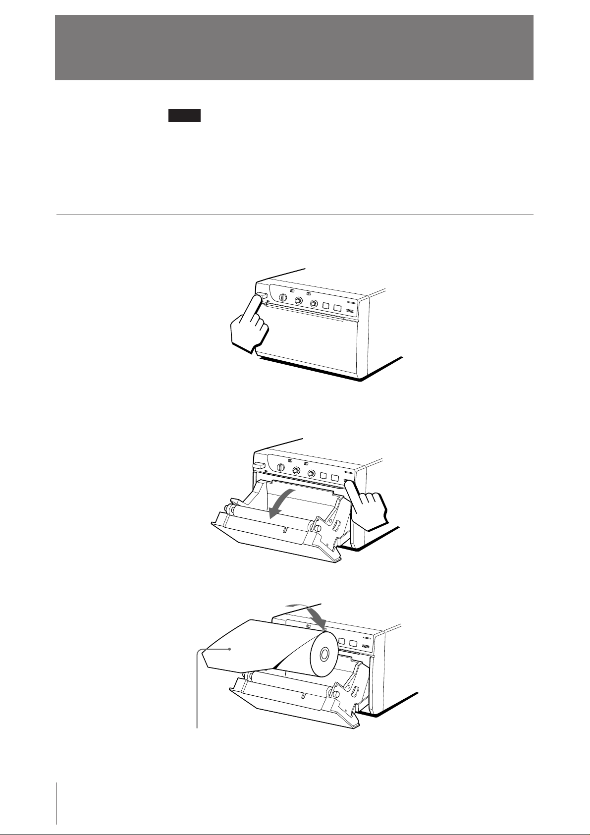
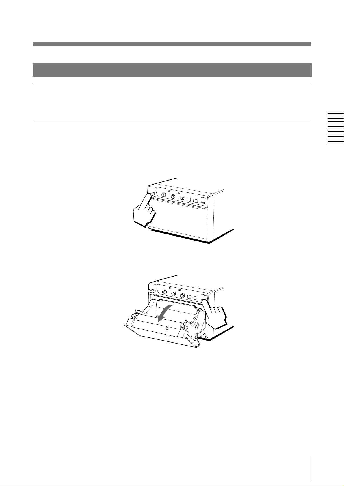
Loading
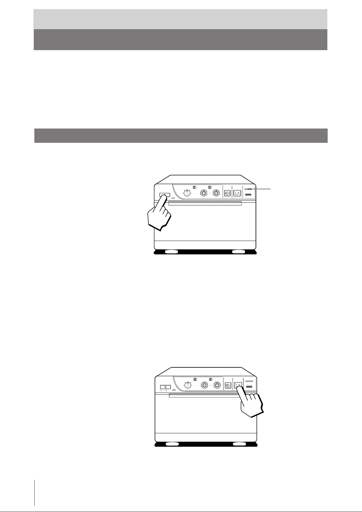
1 Press the power ON/OFF switch to turn on the printer.
7
⁄8
2 Press the OPEN/CLOSE button to open the paper lid.
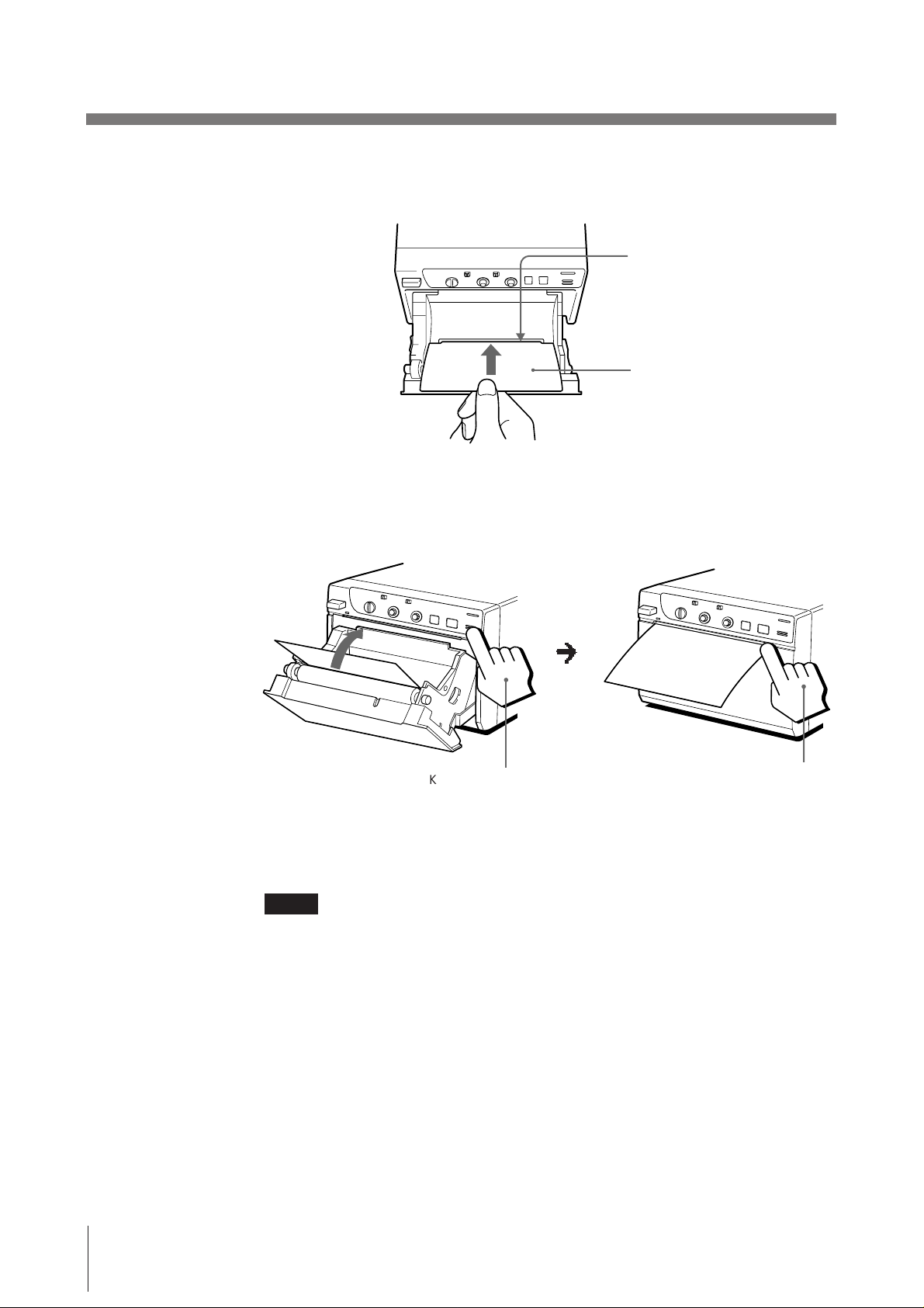
3 Place the paper roll in the printer.
10
Place the paper with the thermo-sensitive
side (printing side) up.
Preparation
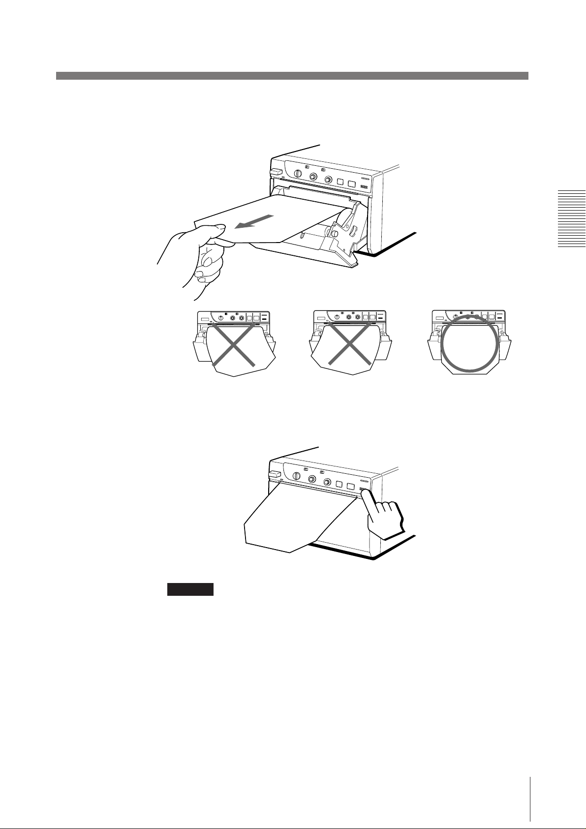
4 Pull out the first 15 to 20 cm (6 to 7
slack in the roll.
7
⁄8 inches) of the paper to remove any
5 Press the OPEN/CLOSE button to close the paper lid.
You can also close the paper lid simply by pushing it.
CAUTION
Keep fingers clear of paper lid assembly and paper cutting blade when paper lid is
closing.
Preparation
11
Operation
Printing
Before making print-outs
• Are the connections correct? (p. 5)
• Is the paper roll loaded properly? (p. 10).
• Is the paper type set correctly? (p. 6).
• Are the DIP switches set correctly? (p. 7 – 9)
• Is the print source being input?
Making Print-outs
1 Press the power ON/OFF switch to turn on the printer.
The power indicator lights.
CONTR
EE
THRU
BRIGHT
COPY PRINT
PAPER EMPTY
OPEN / CLOSE
PAPER EMPTY indicator
ON/ OFF
STD SIDE
STD
NORMAL
SMALL
ZOOM 1 . 5x
ZOOM 2x
LARGE
2 Make sure that the PAPER EMPTY indicator is not lit.
If lit, load paper.
3 Select the printing direction and size.
See “Selecting the Printing Direction” and “Selecting the Printing Size” on
the next page.
4 When the picture you want to print is on the video monitor, press the PRINT
button.
The printer makes a print-out of the picture displayed at the instant you press
the PRINT button.
12
Operation
ON/ OFF
STD SIDE
STD
NORMAL
SMALL
ZOOM 1 . 5x
LARGE
ZOOM 2x
CONTR
EE
THRU
BRIGHT
COPY PRINT
PAPER EMPTY
OPEN / CLOSE
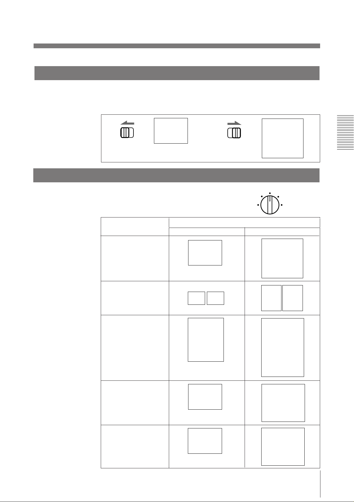
Selecting the printing direction
C
C
C
C
C
You can select the vertical or horizontal direction using the STD/SIDE selector.
To print in the vertical direction, set to STD.
To print in the horizontal direction, set to SIDE.
STD SIDE
Selecting the printing size
You can print in small or large size.
Also you can enlarge the center of the picture by
1.5 or 2 times.
Control position (mode)
NORMAL
SMALL
ABC
STD SIDE
ABC
NORMAL
SMALL
LARGE
Priting size
Vertical (STD) Horizontal (SIDE)
ZOOM 1 . 5x
ZOOM 2x
ABC
ABC
ABC ABC
ABC
ABC
LARGE
ZOOM 1.5X
ZOOM 2X
B
AB
B
ABC
AB
B
Operation
13
Printing (continued)
To print in SMALL mode
Press the PRINT button twice. When you press the PRINT button once, the buzzer
sounds. The printer starts printing after the PRINT button is pressed twice.
Stopping printing midway
Press the OPEN/CLOSE button while printing or while copying. The printer stops
printing.
To stop printing and print another picture displayed on the video
monitor
To do this, the DIP switch 1 (INTERRUPT) must be set to ON (p. 7).
Press the PRINT button while printing or copying. The printer stops printing and
starts printing the picture displayed at the instant you press the PRINT button.
Making copies of the last print-out
Press the COPY button. The printer makes a copy of the last print-out. The last
print-out is retained in the printer’s memory until you press the PRINT button
again or turn the power off.
To copy in different sizes
You can copy the last print-out in different sizes.
Before pressing the COPY button, select the printing size as described in
“Selecting the Printing Size”.
Notes
• If you press the COPY button immediately after turning the power on, the alarm
buzzer will sound as nothing is stored in memory.
• In SMALL mode (p. 13), if you press the COPY button after you have pressed
the PRINT button only once, the alarm buzzer will sound and the printer will not
copy.
To make multiple copies of the same print-out
Press the COPY button as many times as necessary (maximum 11 copies including
the first print-out) while printing or copying the first print-out. Each time you press
the COPY button, the short buzzer sounds.
To stop copying midway
Press the OPEN/CLOSE button.
14
Operation
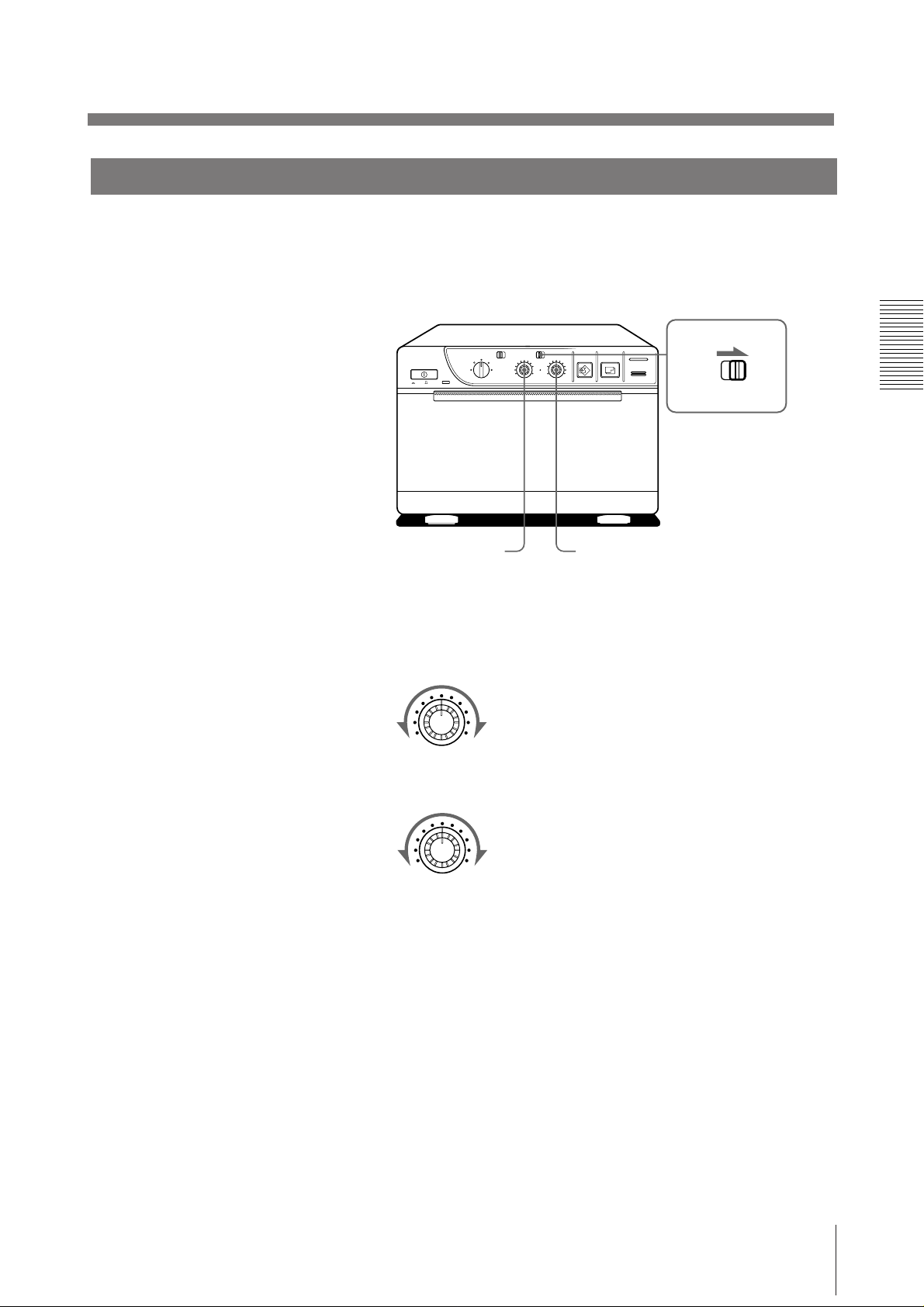
Adjusting the Contrast and Brightness
You can adjust the contrast and brightness of the print-out.
1 Set the THRU/EE selector to EE.
You can check the adjusted picture on the video monitor.
ON/ OFF
STD SIDE
STD
NORMAL
SMALL
ZOOM 1 . 5x
ZOOM 2x
LARGE
CONTR
EE
THRU
BRIGHT
COPY PRINT
PAPER EMPTY
OPEN / CLOSE
THRU
EE
BRIGHTCONTR
2 Adjust the brightness with the BRIGHT control and the contrast with the
CONTR control while watching the picture on the video monitor.
Adjusting the contrast
CONTR
Weaker
Adjusting the brightness
Stronger
BRIGHT
Darker
Brighter
To directly input the video signal from the video equipment, which is
connected to the printer, to the video monitor
Set the THRU/EE selector to THRU. The video signal is directly input to the video
monitor without being processed by the printer’s circuitry.
Operation
15

Others
Precautions
On the safety
• Check the operating voltage before operation.
• Stop operation immediately if any liquid or solid object falls into the cabinet.
• Unplug the unit from a wall outlet if you will not be using it for a long time.
• Do not disassemble the cabinet. Refer servicing to qualified personnel only.
• Do not touch the cutting blade of the printer.
• Keep fingers clear of paper lid assembly and paper cutting blade when paper lid
• Connect the power plug of the printer to a wall outlet having protective earth
On operation
Operate the unit only with a power source specified in “Specifications”.
Unplug the unit and have it checked by qualified personnel.
Disconnect the power cord by grasping the plug. Never pull the cord itself.
is closing.
terminal. The safety earth should be properly established.
On printer carriage
On installation
Do not turn the power off while the printer is printing. The thermal head may be
damaged.
Do not carry and move the printer when the paper roll is placed in the printer.
Doing so may cause malfunction.
• Place the printer on a level and stable surface during operation.
• Do not install the printer near heat sources. Avoid locations near radiators or air
ducts, or place subject to direct sunlight or excessive dust, humidity, mechanical
shock or vibration.
• Provide adequate air circulation to prevent heat build-up. Do not place the printer
on surfaces such as rugs, blankets, etc., or near materials such as curtains and
draperies.
• If the printer is subjected to wide and sudden changes in temperature, such as
when it is moved from a cold room to a warm room or when it is left in a room
with a heater that tends to produce large amounts of moisture, condensation may
form inside the printer. In such cases the printer will probably not work properly,
and may even develop a fault if you persist in using it. If moisture condensation
forms, turn off the power and leave the printer to stand for at least one hour.
16
Others
Maintenance
Cleaning the cabinet
Do not use strong solvents to clean the printer. Thinner or abrasive cleansers will
damage the cabinet.
Cleaning the thermal head
If the print-out is dirty or white stripes appear on the print-outs, clean the thermal
head using the supplied cleaning sheet.
1 Press the power ON/OFF switch to turn on the printer.
2 Press the OPEN/CLOSE button to open the paper lid.
Others
17
Precautions (continued)
3 Insert the cleaning sheet, with the black surface facing down, into the groove
in the paper lid.
4 Press the OPEN/CLOSE button and keep it pressed.
The paper lid closes and the printer starts cleaning the head.
When the buzzer sounds and the printer starts ejecting the cleaning sheet,
release the OPEN/CLOSE button.
Insert into groove.
Cleaning sheet (supplied)
m
Keep the button pressed.
5 Remove the cleaning sheet.
Notes
• Do not press the PRINT or COPY button while the cleaning sheet is in the
printer.
• Clean the head only when necessary. If you clean the head too often, it may
cause malfunction.
When the buzzer
sounds, release the
button.
18
Others

On the Type of Paper
Type of paper
• Use only the Sony UPP-110 series paper. The use of other paper may result in
reduced printer performance and poor print quality.
• The following types of paper are available.
Storing paper
Printing density
TYPE I (Normal)
TYPE II (High density)
TYPE IV (Enhanced)
• Store unused or printed paper in a cool, dark place (below 30°C or 86°F). We
recommend that you store printed paper in a polypropylene pouch.
• Do not store unused or printed paper in hot or humid place.
• Do not leave unused or printed paper in direct sunlight or other bright place for
extended periods.
• Do not allow any volatile organic solvent or vinyl chloride to touch the printed
paper. Alcohol, plastic tape or film will fade the print-out.
• To attach printed paper to another piece of paper, use double-sided adhesive tape,
or water-based or solid glue.
• Do not stack printed paper on or under a diazo copy sheet. The print-out may
become discolor in black.
Type of paper
UPP-110S
UPP-110HD
UPP-110HA
Others
19

Specifications
Thermal head
Thin-film thermal head (with built-in drive
IC) 1024-dot drive
Gradation
256
Resolution (in WIDE 1 mode)
EIA: 970 x 490 dots
CCIR: 970 x 582 dots
Print size (in NORM and WIDE 1 mode)
STD mode
EIA: 95 x 72 mm
CCIR: 95 x 71 mm
SIDE mode
EIA: 127 x 96 mm
CCIR: 127 x 95 mm
Printing speed (in STD and NORM mode)
About 3.9 seconds/screen (aspect ratio 4:3)
Picture memory
768 K x 6 bits
Input/output connectors
VIDEO IN (BNC)
EIA or CCIR
Composite video signals
1.0 Vp-p, 75 ohms/high-impedance (EIA/
CCIR automatically discriminated)
VIDEO OUT (BNC)
EIA or CCIR
Composite video signals
1.0 Vp-p, 75 ohms, loop-through/EE
switchable
REMOTE (stereo minijack)
Power requirements and consumption
UP-880: 120 V AC, 50/60 Hz, 1.8 A
UP-890CE/890MD:
120 V AC, 50/60 Hz, 1.5 A
220 to 240 V AC, 50/60 Hz, 0.8 A
Dimensions
Approx. 154 x 106 x 303 mm (w/h/d) (6
1
4
⁄4 x 12 inches)
Mass
Approx. 3.5 kg (7 lb 11 oz), Main unit only
Protection against electric shock
Class I
Protection against harmful ingress of water
Ordinary
Degree of safety in the presence of flammable
anesthetics or oxygen
Not suitable for use in the presence of
flammable anesthetics or oxygen
Mode of operation
Continuous
Supplied accessories
Paper roll (UPP-110HA) (1)
BNC – BNC connecting cable (1)
AC power cord (1)
Head cleaning sheet (1)
Remote commander RM-91 (1) supplied
with UP-890MD only
Design and specifications are subject to change
without notice.
1
⁄8 x
20
3
2
1
1 GND
2 PRINT SIGNAL (TTL)
Input of LOW pulse over 100 msec.
initiates print.
3 PRINT BUSY (TTL)
Goes HIGH during printing.
Others

Troubleshooting
Symptom
White specks on first few
print-outs.
Printing does not start
when you press the
PRINT button.
Black borders or missing
portions around the printout.
Paper jam
Print-out is dirty.
The printer stops printing
when it prints
continuously black
pictures.
White lines or small
letters on the screen are
not printed clearly.
Small squares appear
over the whole screen.
The print-out is too dark
or too light.
The print-out seems
stretched.
Cause/remedy
When printing with a newly inserted roll of paper,
dust on the surface of the paper may cause white
specks on the print-outs.
m
Feed the paper by pressing the OPEN/CLOSE
button until clean paper appears.
• Paper is not fed.
m
Is the paper slack?
m
Is the power turned on?
m
Are all connections correct? (p. 5)
m
Did you press the PRINT button twice in
SMALL mode?
• When the alarm buzzer sounds:
m
Has the thermal head overheated?
m
Is the video signal of the picture input?
m
Is the paper loaded correctly?
• Paper is fed, but printing does not start.
m
Is the paper loaded with the thermo-sensitive
side up?
This may result according to the video signal input
to the printer.
m
Change the setting of the SCAN switches (DIP
switches 8, 9). (p. 9)
• Open the paper lid by pressing the OPEN/
CLOSE button, then pull the jammed paper
slowly and remove it.
• There is condensation within the unit.
m
Moving the unit suddenly from a cold place to
a warm place often results in condensation
forming. In the event of condensation forming,
remove the paper, turn off the power and leave
the unit for about one to two hours.
The thermal head is dirty.
m
Clean the thermal head with the supplied head
cleaning sheet. (p. 17)
This is likely to occur when the printer prints
continuously 15 or more black pictures. In such a
case, the buzzer sounds. This is because that the
protective circuit works against heat build-up of the
thermal head. Stop printing for a while.
Is the INPUT switch (DIP SWITCH !¡) set to B &
W when the input signal is a black and white
signal? (p. 9)
Is the INPUT switch (DIP switch !¡) set to COLOR
when the input singal is a color signal? (p. 9)
• Is the 75 switch (DIP switch !™) set correctly?
(p. 9)
• Is the GAMMA selector set correctly? (p. 6)
The ASPECT switch (DIP switch 3) is set to 1:1.
m
Set to 4:3. (p. 8)
Others
21
Location and Function of Parts
For details, refer to the pages indicated in parentheses.
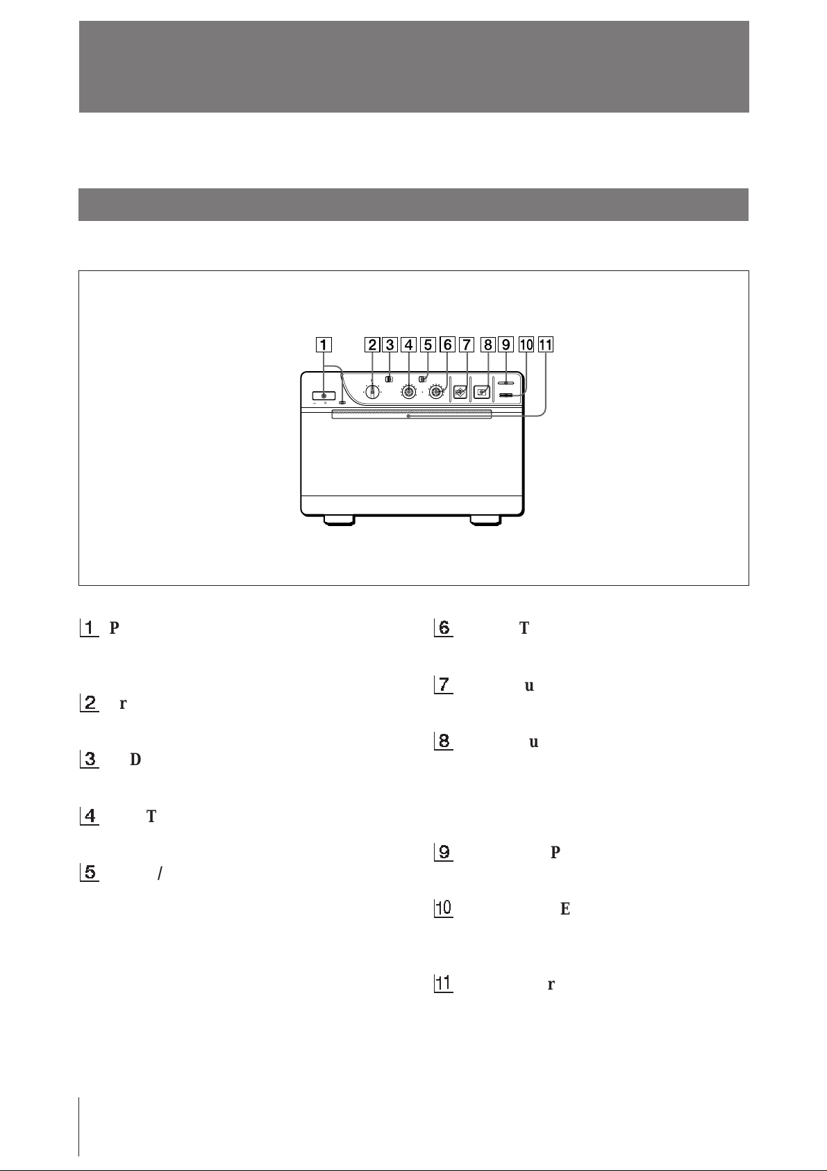
Front
1
Power ON/OFF switch and indicator
Turns the power on. The indicator is lit while
the power is on.
2
Printing size selector (13)
Selects the printing size.
3
STD (standard)/SIDE selector (13)
Selects the printing direction.
4
CONTR (contrast) control (15)
Adjusts the contrast of the print-outs.
5
THRU/EE selector (15)
Selects the video signal output from the
VIDEO OUT connector.
THRU: Input signals are directly output to
the video monitor.
EE: Input signals are output to the video
monitor after being processed by the printer’s
circuitry.
ON/ OFF
STD SIDE
STD
NORMAL
SMALL
ZOOM 1 . 5x
ZOOM 2x
LARGE
EE
THRU
BRIGHT
CONTR
6
PAPER EMPTY
COPY PRINT
OPEN / CLOSE
BRIGHT (brightness) control (15)
Adjusts the brightness of the print-outs.
7
COPY button (14)
Prints another copy of the previous print-out.
8
PRINT button (12)
Prints the picture currently displayed on the
video monitor. The picture displayed when
you press the PRINT button is stored in
memory.
9
PAPER EMPTY indicator
Lights when the printer is out of paper.
!º
OPEN/CLOSE button (10, 14)
Opens or closes the door. Also, stops printing
midway.
!¡
Paper feeder and cutter
Cuts the printing paper.
22
Others
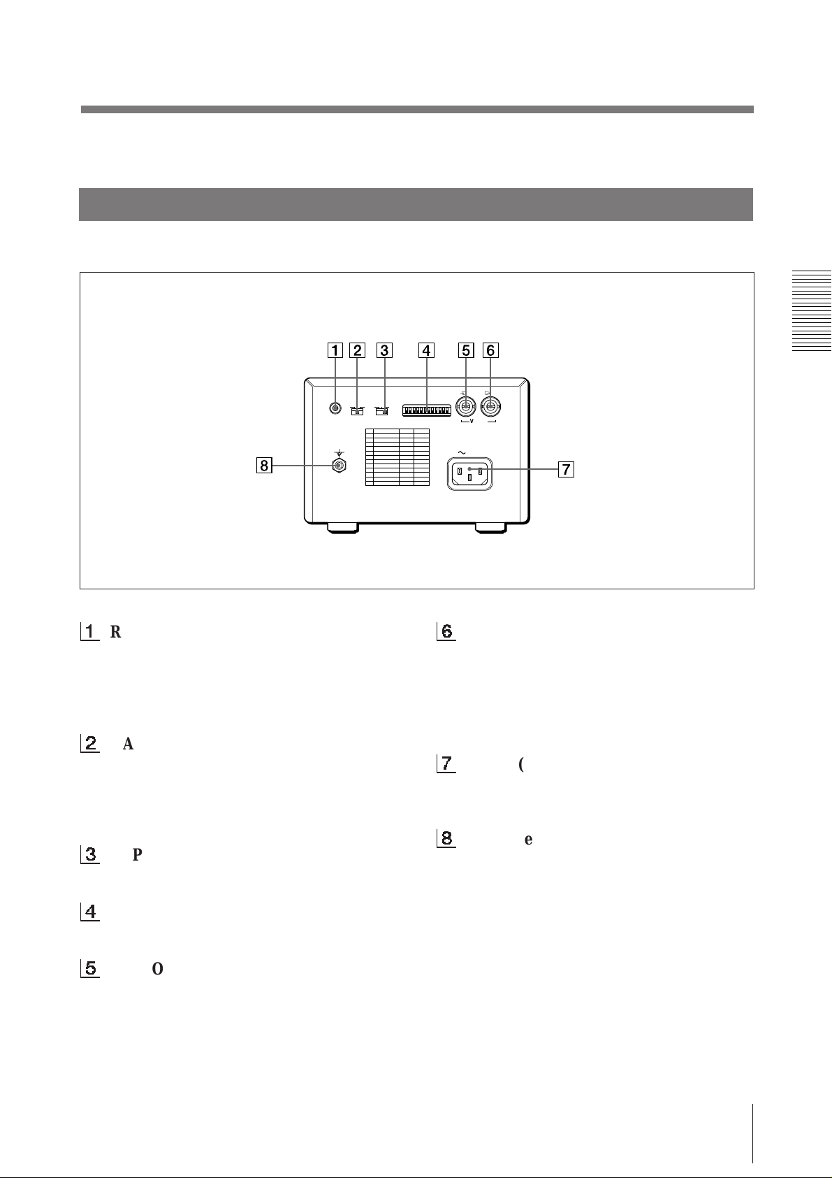
Back
1
REMOTE connector (5)
Connect the RM-91 remote commander for
controlling print operation from a distance.
The RM-91 remote commander is supplied
with UP-890MD only.
2
GAMMA selector (6)
Changes the print mode to that for highdensity printing paper. The selector is
effective when the PAPER TYPE selector is
set to II or IV.
3
PAPER TYPE selector (6)
Sets the type of paper.
REMOTE GAMMA TYPE
PAPER
IIIIII IIIIV
DIP SW
OFF
ON
IN OUT
VIDEO
AC IN
6
VIDEO OUT (output) connector (BNC
type) (5)
Connect to the video input connector of the
video monitor. The output signal type
depends on the setting of the THRU/EE
selector.
7
AC IN (AC power input) connector (5)
Connect to a wall outlet using the supplied
AC power cord.
8
Equipotential terminal
Equipped only with the UP-890CE/890MD.
4
DIP SW (switches) (7 – 9)
Sets the print modes and functions.
5
VIDEO IN (input) connector (BNC
type) (5)
Connect to the video output connector of the
video equipment.
Others
23
Français
AVERTISSEMENT
Afin d’éviter tout risque d’électrocution, ne pas exposer
cet appareil à la pluie ou à l’humidité.
Afin d’écarter tout risque d’électrocution, garder le coffret
fermé. Ne confier l’entretien de l’appareil qu’à un
personnel qualifié.
Pour UP-890CE/890MD
Symboles
Ce symbole indique la borne équipotentielle
qui ramène les différentes parties d’un
système à la même tension.
Instructions de sécurité importantes en vue d’une
utilisation dans un environnement médical
1. Tous les équipements raccordés à cet appareil
doivent être agréés suivant les normes IEC601-1,
IEC950, IEC65 ou les autres normes IEC/ISO
applicables à ces équipements.
2. Si cet appareil est utilisé conjointement avec d’autres
équipements à proximité d’un patient*, ces
équipements doivent être alimentés par un
transformateur d’isolement ou raccordés à la mise à
la terre du système par une borne de terre de
protection sauf s’ils sont agréés suivant la norme
IEC601-1.
* Proximité d’un patient
R1,5m
3. Dans le cas d’une connexion à d’autres équipements,
le courant de fuite peut augmenter.
4. Cet appareil génère, utilise et peut émettre des
radiofréquences. S’il n’est pas installé et utilisé
conformément au mode d’emploi, il peut provoquer
des interférences avec d’autres appareils. Si cet
appareil génère des interférences (ce que l’on peut
facilement contrôler en débranchant le cordon
d’alimentation de l’appareil), appliquez l’une des
mesures suivantes : Installez cet appareil à un autre
endroit en tenant compte de l’autre équipement.
Branchez cet appareil et l’autre équipement sur des
circuits d’alimentation différents. Consultez votre
revendeur.
24

Table des matières
Introduction
Préparation
Opérations
Autres
Vue d’ensemble du système 26
Raccordement 27
Avant l’impression 28
Sélection du type de papier 28
Réglage des microcommutateurs 29
Chargement du papier 32
Impression 34
Réalisation de tirages 34
Sélection du sens d’impression 35
Sélection du format d’impression 35
Réglage du contraste et de la luminosité 37
Précautions 38
Entretien 39
A propos du type de papier 41
Spécifications 42
Dépannage 43
Localisation et fonction des composants 44
Avant 44
Arrière 45
25

Introduction
V ue d’ensemble du système
L’UP-880/890CE/890MD est une imprimante graphique vidéo noir et blanc
pouvant être utilisée pour imprimer des images affichées sur un moniteur vidéo.
Qualité d’impression claire et homogène
• Impression haute définition 10,2 points/mm grâce à l’utilisation d’une tête
thermique à CI d’entraînement ultra-rapide.
• 256 gradations de noir et blanc.
Impression rapide
• Vous obtenez un tirage simple en environ 3,9 secondes en mode STD et NORM.
• Vous pouvez réaliser jusqu’à 11 copies en continu de la même image.
Deux sens d’impression et cinq formats d’impression
• Le sélecteur du sens d’impression sur le panneau frontal vous permet d’imprimer
dans les sens vertical et horizontal.
• La commande de format d’impression située sur le panneau frontal vous permet
de sélectionner cinq types de formats d’impression différents.
Optimisation de l’imprimante par des microcommutateurs
• Vous pouvez réaliser des tirages en commençant par le bas ou par le haut de
l’image en réglant le microcommutateur DIRECTION.
• Vous pouvez sélectionner les rapports d’image 4:3 et 1:1 commutables en réglant
le microcommutateur ASPECT.
• Vous pouvez sélectionner la plage d’impression à l’aide du microcommutateur
SCAN.
• Vous pouvez économiser du papier en réglant le microcommutateur POSTFEED
(fonction d’écomonie de paper).
Identification automatique du signal vidéo
L’imprimante identifie automatiquement le type de signal d’entrée, noir et blanc
(EIA ou CCIR) ou couleur (NTSC ou PAL), et l’imprime avec la même durée et
dans le même format.
Alarme
L’alarme retentit pour vous signaler une erreur de manipulation.
Chargement simple et rapide du papier
Pour charger le papier, il suffit d’ouvrir la réserve papier à l’aide de la touche
OPEN/CLOSE et d’installer le rouleau de papier.
26
Introduction
Préparation
Raccordement
Remarques
• Mettez tous les appareils hors tension avant de procéder au raccordement.
• Branchez le cordon d’alimentation en dernier lieu.
Télécommande
RM-91*
Equipement vidéo
vers le connecteur de
sortie vidéo
Cable de connexion
coaxial fourni
(BNC ˜ BNC)
REMOTE GAMMA TYPE
PAPER
IIIIII IIIIV
vers VIDEO IN
DIP SW
OFF
ON
Moniteur vidéo
couleur/noir et blanc
Câble de connexion
(non fourni)
vers le connecteur
d’entrée vidéoto
vers VIDEO OUTvers REMOTE
IN OUT
VIDEO
AC IN
vers AC IN
vers une prise murale
Cordon d’alimentation
fourni
* La télécommande RM-91 est fournie avec le modèle UP-890MD uniquement.
Préparation
27
A vant l’impression
Sélection du type de papier
Réglez le sélecteur PAPER TYPE suivant le type de papier que vous utilisez.
L’utilisation d’un papier d’une marque autre que Sony peut entraîner une altération
des performances de l’imprimante et de la qualité d’impression.
Type de papier
UPP-110S
UPP-110HD
UPP-110HA
REMOTE GAMMA TYPE
PAPER
IIIIII IIIIV
Position du sélecteur PAPER TYPE
I (Normal)
II (Haute densité)
IV (Supérieur)
DIP SW
OFF
ON
IN OUT
VIDEO
AC IN
GAMMA TYPE
IIIIII IIIIV
PAPER
Si vous utilisez UPP-110HA ou UPP-110HD
Si vous réglez le sélecteur PAPER TYPE sur II ou sur IV, réglez la gradation de la
densité à l’aide du sélecteur GAMMA.
I: Gradation douce
II: Standard
IV: Gradation dure
Préparation
28
Réglage des microcommutateurs
Réglez les microcommutateurs suivant le mode d’impression requis. Avant de
procéder au réglage des microcommutateurs, mettez le système hors tension.
Modifiez les réglages en vous aidant d’un outil finement pointu comme un tournevis
à lame étroite. Les microcommutateurs sont réglés par défaut comme suit :
REMOTE GAMMA TYPE
PAPER
IIIIII IIIIV
DIP SW
OFF
ON
IN OUT
VIDEO
AC IN
DIP SW
OFF
ON
DIP SW FUNCTION TABLE
NO
FUNCTION
1
INTERRUPT
2
POSTFEED
3
ASPECT
4
MEMORY
5
IMAGE
6
MIRROR
7
DIRECTION
8
SCAN
9
10
RESERVED
11
INPUT
12
75
SW-ON
ON
ON
4:3
FRAME
POSI
NORM
NORM
WIDE 1
B&W
ON
SW-OFF
OFF
OFF
1:1
FIELD
NEGA
REV
REV
WIDE 2
NORM
COLOR
OFF
1
Contacteur d’interruption marche/arret (INTERRUPT
ON/OFF)
Pour interrompre un cycle d’impression et imprimer une nouvelle image
lorsque vous appuyez sur la touche PRINT en cours d’impression, réglez cet
interrupteur sur ON.
Pour que la touche PRINT soit sans effet durant l’impression et que
l’imprimante poursuive le cycle, réglez-le sur OFF.
Si vous appuyez sur la touche PRINT pendant une impression en mode OFF,
l’alarme retentit.
2
Contacteur POSTFEED march/arret (POSTFEED ON/OFF)
Pour avancer une longueur de papier supplémentaire, réglez ce commutateur
sur ON.
Pour économiser le papier en faisant seulement avancer une étroite bande de
papier après l’impression d’une image, réglez-le sur OFF. Vous pouvez
réaliser davantage de tirages par rouleau de papier d’impression en réglant ce
commutateur sur OFF, mais vous devez dans ce cas sortir le papier et le
couper manuellement.
Préparation
29
Avant l’impression (suite)
275
87654321
475
50
250
9
4
5
5
7
5
4
3
3
2
3
2
30
10
7
0
3
275
87654321
475
50
250
9
4
5
5
7
5
4
3
3
2
3
2
30
10
7
0
3
275
87654321
475
50
250
9
4
5
5
7
5
4
3
3
2
3
2
30
10
7
0
3
275
87654321
475
50
250
9
4
5
5
7
5
4
3
3
2
3
2
30
10
7
0
3
3
Commutateur de rapport d’image (ASPECT 4:3/1:1)
En principe, réglez ce commutateur sur 4:3. Si le rapport hauteur/largeur du
signal vidéo est de 1:1, réglez-le sur 1:1.
Le tirage sera plus long qu’un tirage en 4:3.
1
2
3
3
5
2
3
30
4
3
3
4
1 357 7 531
4
3
3
4
30
3
2
5
3
3
2
1
4 : 3
5
2
3
1
3
2
3
30
4
3
3
4
4
3
3
4
30
3
2
5
3
3
2
1
1
2
3
3
5
2
3
30
4
3
3
4
1 357 7 531
4
3
3
4
30
3
2
5
3
3
2
1
5
3
1
4
3
3
4
4
3
3
4
5
3
1
1 : 1
4
Touche de mémoire (MEMORY FRAME/FIELD)
En principe, réglez ce commutateur sur FRAME (ON). Pour imprimer une
image avec un sujet en déplacement rapide (comme un ballon), le tirage
risque d’être flou. Si cela se produit, réglez-le sur FIELD. La définition ainsi
obtenue sera moins bonne, mais le tirage sera moins flou.
5
Touche d’image (IMAGE POSI/NEGA)
Réglez normalement ce commutateur sur POSI (ON). Pour réaliser des tirages
négatifs, réglez-le sur NEGA (OFF).
Remarque
Si vous réglez le sélecteur THRU/EE sur la position EE, l’appareil imprime
des images positives, quel que soit le réglage du commutateur IMAGE POSI/
NEGA.
2
3
2
3
30
30
3
2
3
2
6
Touche d’impression miroir (MIRROR NORM/REV)
Réglez normalement ce commutateur sur NORM (ON). Pour imprimer les
côtés gauche et droit inversés en miroir, réglez ce commutateur sur REV
(OFF).
7
Touche de sens d’impression (DIRECTION NORM/REV)
Déterminez si l’impression doit commencer par le haut ou par le bas de
l’image.
Normalement, laissez ce commutateur sur NORM (ON). L’impression est
alors réalisée depuis le bas de l’écran. Pour lancer l’impression à partir du
haut, réglez-le sur REV (OFF).
1
2
3
3
5
2
3
30
4
3
3
4
1 357 7 531
4
3
3
4
Préparation
30
30
3
2
5
3
3
2
1
NORM
5
2
3
1
3
2
3
30
4
3
3
4
4
3
3
4
30
3
2
5
3
3
2
1
1
2
3
3
5
2
3
30
4
3
3
4
4
3
3
4
30
3
2
3
1
3
2
5
1
2
3
3
5
2
3
30
4
3
3
4
1 357 7 531
4
3
3
4
30
3
2
5
3
3
2
1
REV
 Loading...