

3-864-335-12(1)
Integrated
Ster eo Amplifier
Operating Instructions
Mode d’emploi
Manual de instrucciones
Manual de instruções
GB
F
ES
P
TA-FB920R
TA-FB820R
TA-FB720R
1998 by Sony Corporation
WARNING
To prevent fire or shock
hazard, do not expose the unit
to rain or moisture.
To avoid electrical shock, do
not open the cabinet. Refer
servicing to qualified
personnel only.
Do not install the appliance in
a confined space, such as a
bookcase or built-in cabinet.
Precautions
On safety
• Do not disassemble the cabinet as this
may result in an electrical shock.
Refer servicing to qualified personnel
only.
• Should any solid object or liquid fall
into the cabinet, unplug the amplifier
and have it checked by qualified
personnel before operating it any
further.
On power sources
• Before operating the amplifier, check
that the operating voltage of the
amplifier is identical with your local
power supply. The operating voltage
is indicated on the nameplate at the
rear of the amplifier.
• If you are not going to use the
amplifier for a long time, be sure to
disconnect the amplifier from the wall
outlet. To disconnect the AC power
cord (mains lead), grasp the plug
itself; never pull the cord.
• AC power cord must be changed only
at the qualified service shop.
On the prevention of howling
Do the following:
—lower the volume.
—keep the turntable as far from the
speakers as possible.
—use commercially available audio
insulators on the bottom of the
turntable.
—keep the microphone away from the
speakers during use.
For further protection against howling,
set the speakers or turntable on top of a
heavy wooden board or concrete slab.
If you have any questions or problems
concerning your amplifier, please
consult your nearest Sony dealer.
On placement
• Place the amplifier in a location with
adequate ventilation to prevent heat
built-up and prolong the life of the
amplifier.
• Do not place the amplifier near heat
sources, or in a place subject to direct
sunlight, excessive dust or mechanical
shock.
• Do not place anything on top of the
cabinet that might block the
ventilation holes and cause
malfunctions.
On operation
Before connecting other components, be
sure to turn off and unplug the
amplifier.
On cleaning the amplifier
Clean the cabinet, panel and controls
with a soft cloth slightly moistened with
a mild detergent solution. Do not use
any type of abrasive pad, scouring
powder or solvent such as alcohol or
benzine.
GB
2
Welcome!
Thank you for purchasing the Sony
Integrated Stereo Amplifier. Before
operating the amplifier, please read this
manual thoroughly and retain it for
future reference.
About This Manual
The instructions in this manual are for
models TA-FB920R, FB820R, and
FB720R. Check your model number by
looking at the rear panel of your
amplifier. The TA-FB920R is the model
used for illustration purposes unless
stated otherwise.
Any difference in operation is clearly
indicated in the text, for example,
“TA-FB920R only.”
Conventions
• Instructions in this manual describe
the controls on the amplifier.
For details on the remote buttons
control, see ”Remote Button
Descriptions” on page 12.
• The following icon is used in this
manual:
TABLE OF CONTENTS
Getting Started
Hookup Overview 4
Audio Component Hookups 4
Speaker System Hookups 5
Mains Lead Hookups 6
Listening to the Music 7
Recording 9
Additional Information
Troubleshooting 10
Specifications 10
Rear Panel Descriptions 12
Remote Button Descriptions 12
GB
Unpacking
Check that you have received the following supplied items:
• Remote commander (remote) (1) RM-S316
• Sony batteries R6 (size-AA) (2)
z Indicates hints and tips for making
the task easier.
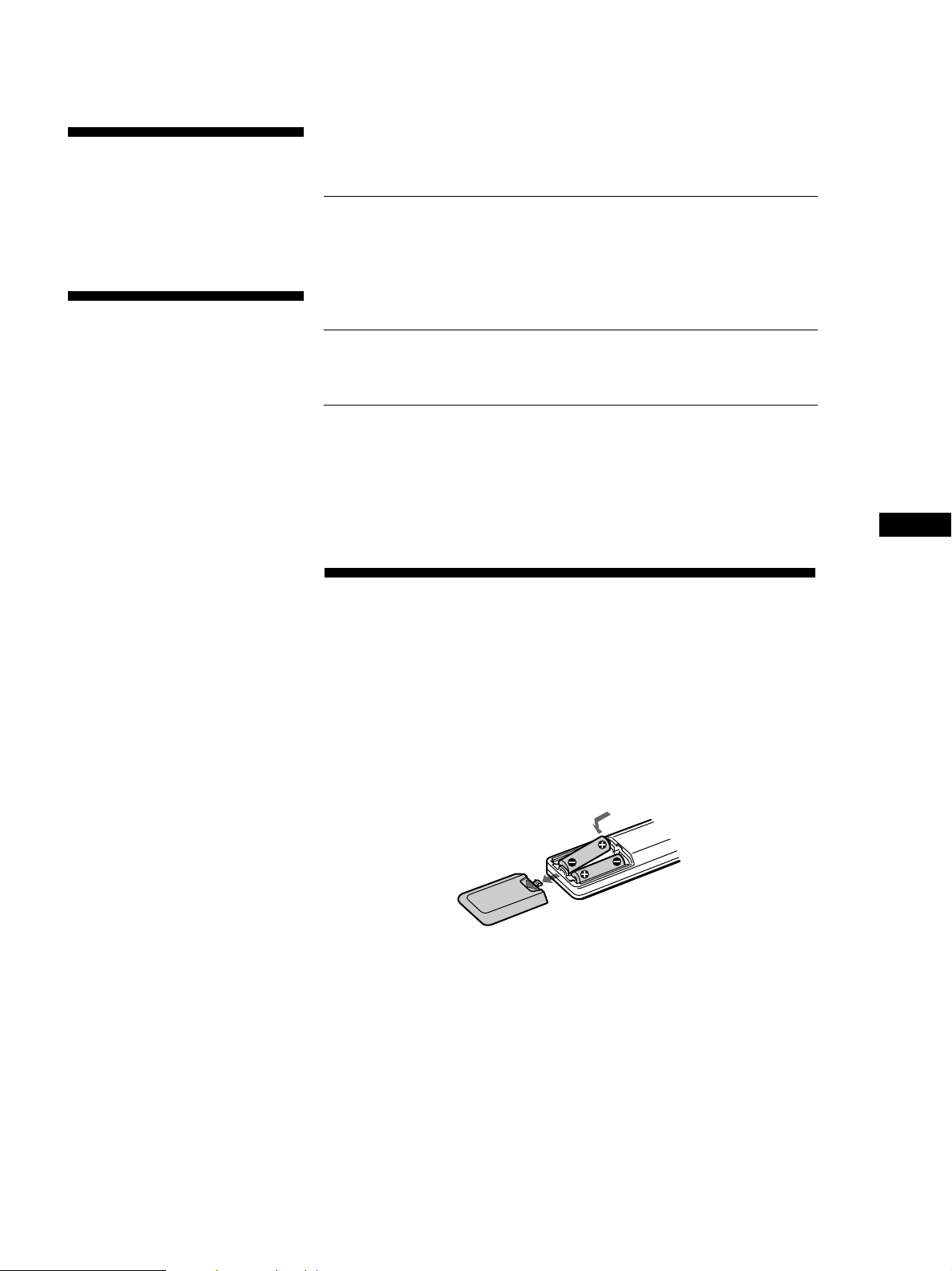
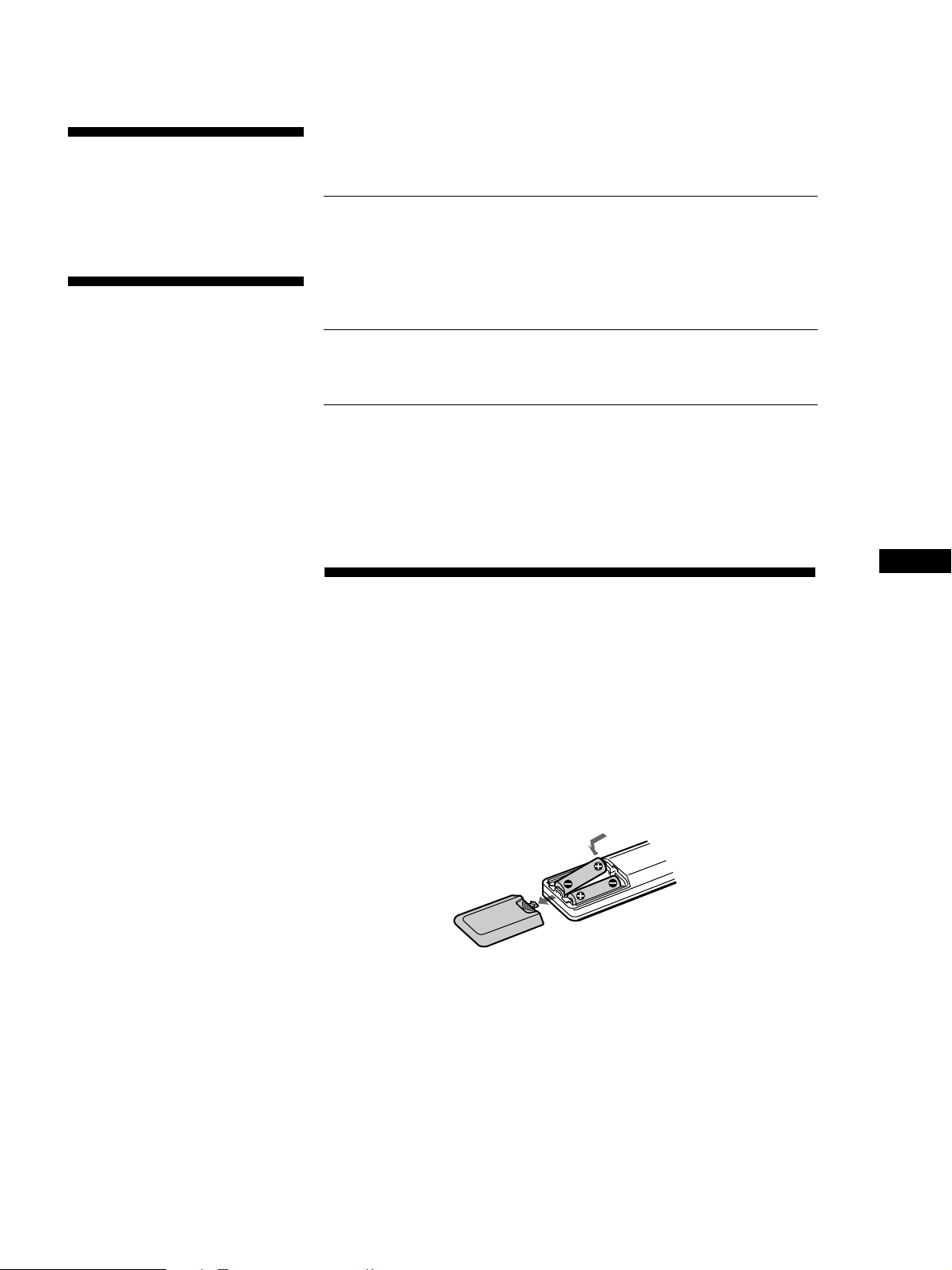
Inserting batteries into the remote
Insert two R6 (size-AA) batteries, matching the + and – on the batteries with
the markings inside the battery compartment. When using the remote, point
it at the remote control sensor g on the amplifier.
z When to replace batteries
With normal use, the batteries should last for about 6 months. When the remote
no longer operates the amplifier, replace all the batteries.
Notes
• Do not leave the remote near an extremely hot or humid place.
• Do not drop any foreign object into the remote casing, particularly when replacing
the batteries.
• Do not expose the remote sensor to direct sunlight or lighting equipment. Doing
so may cause a malfunction.
• If you don’t use the remote for an extended period of time, remove the batteries to
avoid possible damage from battery leakage and corrosion.
GB
3
Getting Started
PHONO TAPE1/DAT
EON CONTROL INTUNER TAPE2/MDCD
y
AUX
SPEAKERS
EON CONTROL
R
B
A
L
++––
RL
++––
TAPE1/DAT
L
REC OUT IN
IMPEDANCE USE 4–16Ω
A+B USE 8–16Ω
BI WIRE USE 4–16Ω
IN
R
L
R
TAPE2/MD
REC OUT IN
AUXINCDINTUNER
IN
L
R
PHONO
IN
SIGNAL
GND
y
Getting Started
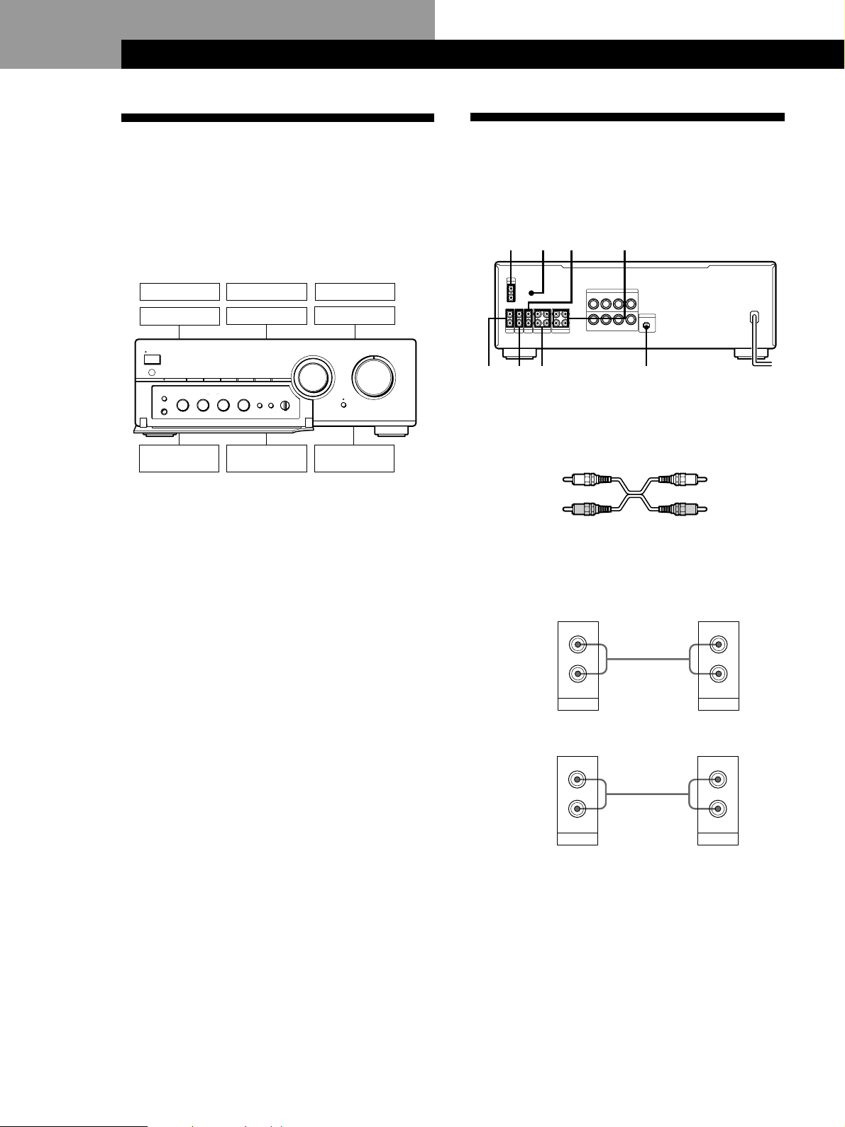
Hookup Overview
The amplifier allows you to connect and control the
following audio components. Follow the hookup
procedure indicated for each component that you want
to connect.
To learn the location and name of each jack, see ”Rear
Panel Descriptions” on page 12.
DAT deck
MD deck
PROTECTION
U
g
TAPE1/DATEON LINK CD TUNER PHONOAUXTAPE2/MD
SPEAKERS
EON LINK
A
OFF
B
•
•
•
A
+
B
•
PHONES
–10+
Speaker (L)
Before you get started
• Turn off the power to all components before making
any connections.
• Do not connect the mains leads of the various
components until all connections are completed.
• Use the audio connecting cords supplied with each
component for hooking up with the amplifier.
Purchase and use optionally available cords as
required.
• Be sure to make connections firmly to prevent hum
and noise.
• When connecting an audio connecting cord, be sure
to match the R (right) and L (left) jacks of the
amplifier to the R and L jacks on the other
components.
TONE
BASS
0
•
•
•
10
Tape deck
Turntable
TREBLE
BALANCE
0
•
•
•
•
•
–10+
10
LEFT RIGHT
TV or video
•
LOUDNESS
SUBSONIC
Ø ON ø OFF Ø ON ø OFF
deck
TAPE MONITOR
SOURCE
TAPE1 TAPE2
•
•
•
CD player
INPUT SELECTOR
SOURCE DIRECT
Speaker (R)
Tuner
VOLUME
010
Audio Component Hookups
Overview
Here you learn how to connect your audio components
to the amplifier.
What cords will I need?
Audio connecting cord (not supplied) (2 for each tape deck,
DAT deck, or MD deck; 1 for other components)
White (L)
Red (R) Red (R)
Hookups
The arrow ç indicates signal flow.
CD player
Amplifier
Tuner
L
R
IN
CD
Amplifier
L
R
IN
TUNER
Ç
Ç
White (L)
CD player
L
R
LINE
OUTPUT
Tuner
L
R
LINE
OUTPUT
GB
4
Tape deck, DAT deck, or MD deck
Amplifier
Tape deck
Getting Started
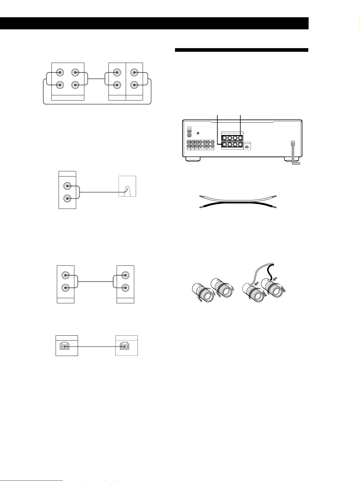
Speaker System Hookups
L
R
REC OUT IN
TAPE1/DAT
Ç
ç
LINE
OUTPUT
L
R
LINE
INPUT
Use the configuration above to connect the OUTPUT and
INPUT jacks of:
—a tape deck or DAT deck to the TAPE1/DAT jacks.
—a tape deck or MD deck to the TAPE2/MD jacks.
Turntable
Amplifier
PHONO
IN
L
R
Ç
Turntable
Note
To prevent hum, connect the earth lead to SIGNAL GND (y)
on the amplifier.
TV or video deck
Amplifier TV or video deck
L
R
IN
AUX
Ç
L
R
LINE
OUTPUT
Overview
Here you learn how to connect speakers to the
amplifier. You can connect two pairs of speakers,
SPEAKERS A and B.
SPEAKERS A SPEAKERS B
PHONO
SIGNAL
IN
GND
L
y
R
L
R
REC OUT IN
IN
REC OUT IN
TAPE1/DAT
TAPE2/MD
AUXINCDINTUNER
L
R
SPEAKERS
++––
R
B
A
++––
RL
IMPEDANCE USE 4–16Ω
A+B USE 8–16Ω
BI WIRE USE 4–16Ω
L
EON CONTROL
IN
What cords will I need?
Speaker cord (not supplied) (1 for each speaker)
(+)
(–)
Twist the stripped ends of the cord about 15mm. Be sure to
match the speaker cord to the appropriate terminal on the
components: + to + and – to –. If the cords are reversed, the
sound will be distorted and will lack bass.
(+)
(–)
Hookups
}
}
]
]
EON CONTROL
Amplifier
EON CONTROL
Tuner
EON CONTROL
Ç
IN
If your tuner is equipped with an EON CONTROL OUT
terminal, connect it to the EON CONTROL IN terminal on
the amplifier to allow use of the EON (Enhanced Other
Networks) function of the RDS (Radio Data System) (see
page 8).
OUT
GB
5

Getting Started
Connecting to bi-wire system speakers
Since the two pairs of speaker terminals on your
amplifier, SPEAKERS A and B, can provide
simultaneous speaker output, you can use them to
connect a bi-wire speaker system. To drive both
speaker systems simultaneously, set SPEAKERS to
A+B.
To select the speaker system A or B
Set SPEAKERS to A or B. To drive both speaker systems
simultaneously, set SPEAKERS to A+B.
Note
Use speakers with a nominal impedance of 4 to 16 ohms.
When outputting at the same time to two speaker systems,
use speakers with a nominal impedance of 8 to 16 ohms.
Mains Lead Hookups
Connecting the mains lead
Connect the mains lead from this amplifier and from
your audio/video components to wall outlets.
z You can power other components through AC
OUTLET on the amplifier (unavailable on the U.K.
model)
By connecting other audio components to AC OUTLET
on the amplifier, you can supply power to the
connected components through the amplifier and turn
them all on or off when you turn the amplifier on or off.
Caution
Make sure that the total power consumption of all
components connected to the outlets on the amplifier does
not exceed 100 watts. Do not connect electrical home
appliances such as an electric iron, fan, TV, or other highwattage appliances to these outlets.
Note
Separate the mains lead, audio connecting cords and speaker
cords. Noise or sound deterioration may occur when audio
connecting cords are in contact with the mains lead, or when
the mains lead or speaker cords are placed near the tuner’s
loop aerial or aerial wire.
GB
6
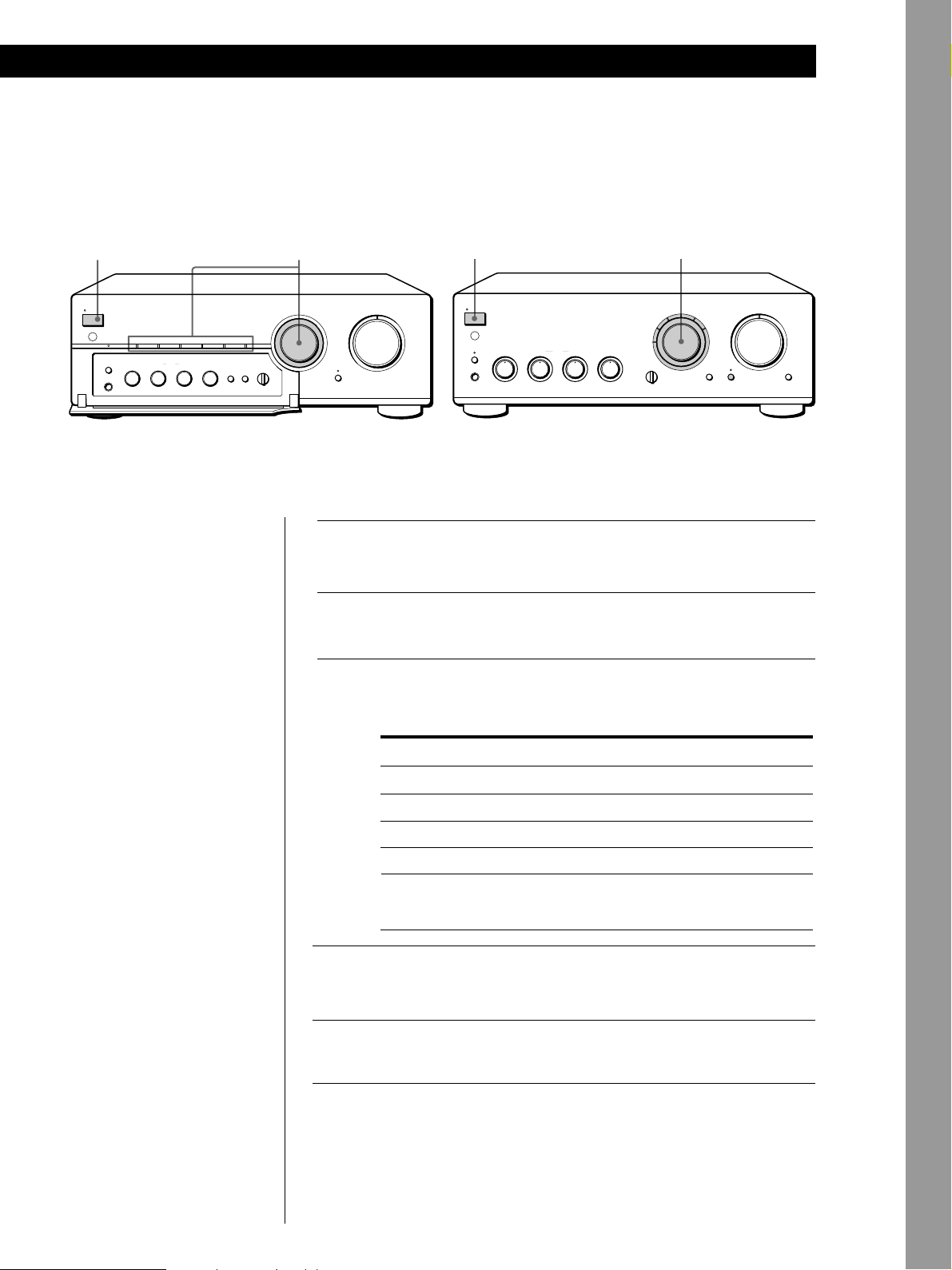
Basic Operations
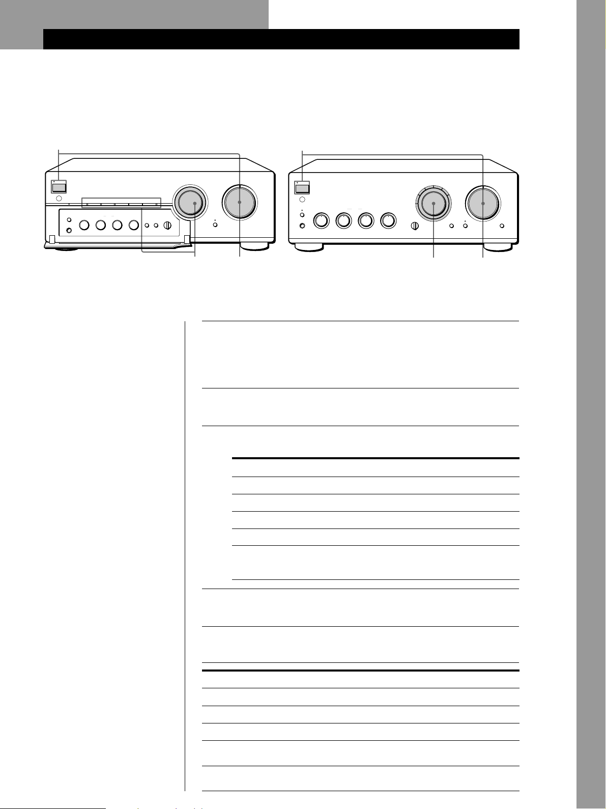
Listening to the Music
TA-FB920R TA-FB820R/FB720R
Basic Operations
1
PROTECTION
U
g
TAPE1/DATEON LINK CD TUNER PHONOAUXTAPE2/MD
SPEAKERS
TONE
BASS
TREBLE
EON LINK
A
OFF
B
•
•
•
A
+
B
•
PHONES
–10+
•
z To listen through the
headphones
Connect the headphones to
PHONES and set
SPEAKERS to OFF.
z To listen directly to the
input signal
Press SOURCE DIRECT so
that the indicator lights up.
Since the circuits of TONE
controls, BALANCE control,
LOUDNESS button, and
SUBSONIC button are
bypassed, you cannot adjust
bass, treble, the balance,
reinforce the bass and treble,
or reduce subsonic noise
components while listening
to a source directly.
Note
Avoid high speaker output at
which the sound is distorted.
High-frequency distortion may
damage the tweeters.
BALANCE
0
0
•
•
•
LOUDNESS
•
10
–10+
Ø ON ø OFF Ø ON ø OFF
•
•
•
•
10
LEFT RIGHT
1
SOURCE DIRECT
VOLUME
010
5
PROTECTION
U
g
EON LINK
A
PHONES
SPEAKERS
A0
B
OFF
+
B
–10+
BASS
TONE
TREBLE
BALANCE
0
–10+
•
•
•
10
LEFT RIGHT
•
10
INPUT SELECTOR VOLUME
CD
TAPE2/MD
TAPE1/DAT
TAPE MONITOR
SOURCE
TAPE1
3
TUNERAUX
PHONO
LOUDNESS
Ø ON ø OFF
Press U to turn on the amplifier and turn VOLUME fully
counterclockwise to prevent damaging the speakers with
excessive output.
The PROTECTION indicator lights up, then goes off.
Turn on the programme source you want to listen to.
Set INPUT SELECTOR to the respective programme source.
The indicator for the programme source lights up.
To listen to a
Record
Radio broadcast
Compact disc
Source connected to AUX
Source connected to:
—TAPE1/DAT
—TAPE2/MD
Turn INPUT SELECTOR for
PHONO
TUNER
CD
AUX
TAPE1/DAT
TAPE2/MD
Start the programme source.
SOURCE DIRECT
010
5
SUBSONIC
Ø ON ø OFF
Basic Operations
INPUT SELECTOR
TAPE MONITOR
SUBSONIC
SOURCE
•
•
TAPE1 TAPE2
•
3
1
2
3
4
Adjust the volume by turning VOLUME.
5
To
Adjust the bass
Adjust the treble
Adjust the balance
Reinforce the bass and treble at low
listening level
Reduce subsonic noise components
created by warped records, etc.
Press or turn
BASS
TREBLE
BALANCE
LOUDNESS
SUBSONIC
GB
7
Basic Operations
z What is the Enhanced
Other Networks (EON)?
One convenient RDS service
is ”Enhanced Other
Networks” (or ”EON”).
This allows the unit to
automatically switch to a
programme type of your
choice when one starts in
your broadcast area.
To receive the Enhanced Other Networks (EON) programmes
When your ampifier is connected to a Sony tuner with the EON CONTROL
system, the amplifier switches to any EON programme that is broadcast in
your EON area, and switches back to the last selected programme source
when the programme ends.
TA-FB920R TA-FB820R/FB720R
EON LINK
PROTECTION
U
g
SPEAKERS
EON LINK
OFF
•
A
+
B
•
PHONES
TAPE1/DATEON LINK CD TUNER PHONOAUXTAPE2/MD
A
B
•
•
–10+
INPUT SELECTOR
TONE
BASS
TREBLE
BALANCE
0
0
•
•
•
•
•
•
10
–10+
10
LEFT RIGHT
TAPE MONITOR
•
LOUDNESS
SUBSONIC
SOURCE
Ø ON ø OFF Ø ON ø OFF
•
•
TAPE1 TAPE2
•
•
•
EON LINK
PROTECTION
U
g
EON LINK
A
+B
PHONES
SPEAKERS
BASS
A0
B
OFF
•
–10 +10
INPUT SELECTOR
TAPE2/MD
BALANCE
LEFT RIGHT
TAPE1/DAT
•
•
TAPE MONITOR
SOURCE
TAPE1
TONE
TREBLE
0
•
–10 +10
1 Make sure that the amplifier and the tuner are connected through the
EON CONTROL terminals (see page 5).
2 Press EON LINK so that the indicator lights up.
Whenever an EON programme starts on the radio frequency that your
tuner is set to, you will receive it.
To cancel EON reception
Press EON LINK again so that the indicator goes off.
CD
TUNERAUX
PHONO
LOUDNESS
Ø ON ø OFF
Notes
• If you select another programme source while receiving an EON programme, EON
reception ends. However, as long as the EON LINK indicator lights up, you can
receive EON programmes automatically.
• Make sure to cancel EON reception before starting to record since an EON
programme may interfere with your recording.
• If you activate the Tape Monitor function (see page 9) while the EON LINK indicator
is lit, the indicator goes off and you cannot receive EON programmes. If this
happens, deactivate the Tape Monitor function so that the indicator lights up again.
GB
8
Recording
TA-FB920R TA-FB820R/FB720R
Basic Operations
13
PROTECTION
U
g
TAPE1/DATEON LINK CD TUNER PHONOAUXTAPE2/MD
SPEAKERS
TONE
BASS
TREBLE
EON LINK
A
OFF
B
•
•
•
A+B
•
PHONES
•
–10 +10
BALANCE
0
0
•
•
•
LOUDNESS
SUBSONIC
•
–10 +10
Ø ON ø OFF Ø ON ø OFF
•
•
•
•
LEFT RIGHT
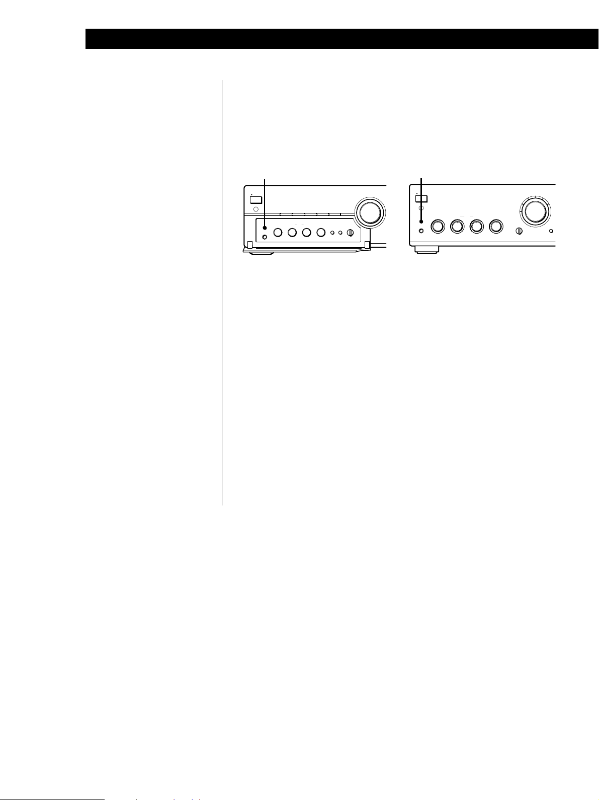
z You can record the same
source on two recording
components at the same
time
z You can monitor the
recorded sound (Tape
Monitor function)
You can monitor the
recorded sound if the tape
deck you are recording on
has separate playback and
recording heads.
To monitor the sound, set
TAPE MONITOR to TAPE1
or TAPE2.
Note that on the
TA-FB820R/FB720R, you
can monitor the only sound
being recorded from the
TAPE1/DAT jacks.
TAPE MONITOR
SOURCE
TAPE1 TAPE2
•
INPUT SELECTOR
•
•
1
2
3
VOLUME
SOURCE DIRECT
010
Press U to turn on the amplifier.
Turn on the programme source you want to record.
Select the programme source that you want to record by
turning INPUT SELECTOR.
The indicator for the programme source lights up.
To record a
Record
Radio broadcast
Compact disc
Source connected to AUX
Source connected to:
—TAPE1/DAT
—TAPE2/MD
1 3
PROTECTION
U
g
EON LINK
A
PHONES
SPEAKERS
A0
B
OFF
+
B
–10+
BASS
TONE
TREBLE
BALANCE
0
–10+
•
•
•
10
LEFT RIGHT
•
10
INPUT SELECTOR VOLUME
CD
TAPE2/MD
TAPE1/DAT
TAPE MONITOR
SOURCE
TAPE1
Set INPUT SELECTOR to
PHONO
TUNER
CD
AUX
TAPE1/DAT
TAPE2/MD
TUNERAUX
PHONO
LOUDNESS
ON ø OFF
Ø
SOURCE DIRECT
010
SUBSONIC
ON ø OFF
Ø
Basic Operations
Prepare the recording component for recording, then start
4
recording.
Start playing the programme source.
5
GB
9

Additional Information
Troubleshooting
If you experience any of the following difficulties while
using the amplifier, use this troubleshooting guide to
help you remedy the problem. Should any problem
persist, consult your nearest Sony dealer.
No sound output.
/ Connect the audio connecting cords firmly.
/ Connect the amplifier and other audio components
correctly.
/ Turn INPUT SELECTOR to the appropriate programme
source.
No audio from one channel or unbalanced speaker
output.
/ Turn BALANCE to adjust the balance.
/ Check the speaker and input connections of silent
channel.
Weak bass or treble.
/ Adjust the TONE controls.
/ Change speaker positions or room conditions to
eliminate obstructions in sound path.
Distorted sound.
/ Improperly selected input signal.
/ Insufficient input capacity of speakers. Lower the
volume.
Lack of bass or ambiguity in instrument positions.
/ Speaker cord and terminal polarity are reversed.
Reconnect the cords with correct polarity.
Hum or noise.
/ Ground the turntable system (see page 5).
/ Connect the audio connecting cords firmly.
/ The amplifier is picking up interference from a TV set.
Move the amplifier away from the TV set or turn the TV
set off.
The remote does not function.
/ Remove any obstructions between the remote control
sensor on the amplifier and the remote.
/ Point the remote towards the remote sensor on the front
of the amplifier.
/ The remote is too far from the amplifier. Move closer to
the amplifier.
/ Replace the batteries in the remote.
The PROTECTION indicator lights up and/or sudden loss
of audio.
/ Check if a short-circuit has occurred. Turn off the
amplifier and check the connected components and
speakers.
Specifications
Amplifier section
DIN power output
TA-FB920R (Continental Europe):
120 W + 120 W (4 ohms at 1 kHz)
80 W + 80 W (8 ohms at 1 kHz)
TA-FB920R (U.K.):
100 W + 100 W (4 ohms at 1 kHz)
65 W + 65 W (8 ohms at 1 kHz)
TA-FB820R: 100 W + 100 W (4 ohms at 1 kHz)
65 W + 65 W (8 ohms at 1 kHz)
TA-FB720R: 90 W + 90 W (4 ohms at 1 kHz)
60 W + 60 W (8 ohms at 1 kHz)
Total harmonic distortion
Less than 0.008% (at 10 W output)
Frequency response
PHONO (20 Hz - 20 kHz): RIAA equalization curve
±0.5 dB
TUNER, CD, AUX, TAPE1/DAT, TAPE2/MD:
7 Hz - 100 kHz
S/N (network A)
PHONO
TA-FB920R/FB820R: 94 dB
TA-FB720R: 90 dB
TUNER, CD, AUX , TAPE1/DAT, TAPE2/MD:
105 dB
Output voltage / impedance
REC OUT 1, 2: 150 mV, 1 kilohm
PHONES: 10 mW (at 8 ohms)
Speakers impedance
4 - 16 ohms, 8 - 16 ohms (SPEAKERS A+B)
Damping factor
100 (8 ohms, 1 kHz)
+0–3
dB
10
GB

General
System
Power amplifier: Pure-complementary SEPP OCL
power amplifier with all stages directly coupled
Preamplifier: Low-noise, equalizer amplifier
Power requirements
230 V AC, 50/60 Hz
Power consumption
TA-FB920R: 210 W
TA-FB820R: 180 W
TA-FB720R: 170 W
Dimensions (approx.) (w/h/d)
TA-FB920R: 430 × 150 × 410 mm
TA-FB820R/FB720R: 430 × 150 × 405 mm
incl. projecting parts and controls
Mass (approx.)
TA-FB920R: 10.3 kg
TA-FB820R: 9.3 kg
TA-FB720R: 8.6 kg
Additional Information
Supplied accessories
See page 3.
Design and specifications are subject to change without
notice.
11
GB
Additional Information
Additional Information
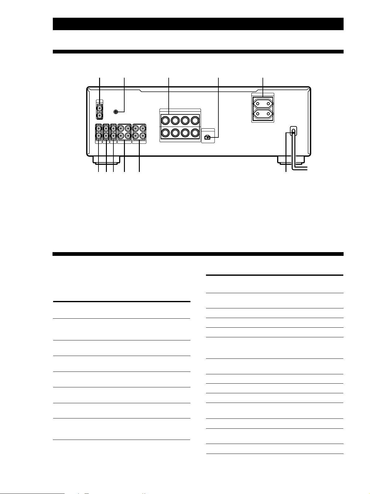
Rear Panel Descriptions
3 51
PHONO
SIGNAL
IN
L
R
L
R
GND
y
B
L
A
AUXINCDINTUNER
REC OUT IN
TAPE2/MD
IN
REC OUT IN
TAPE1/DAT
R
IMPEDANCE USE 4–16Ω
SPEAKERS
++––
R
++––
RL
0!¡ 9 8 7 6
1 PHONO
2 y (SIGNAL GND)
3 SPEAKERS A/B
4 EON CONTROL IN
5 AC OUTLET (unavailable on the TA-FB920R (U.K.
model))
A+B USE 8–16Ω
BI WIRE USE 4–16Ω
L
42
EON CONTROL
IN
6 Mains lead
7 TAPE1/DAT
8 TAPE2/MD
9 AUX
0 CD
!¡ TUNER
AC OUTLET
SWITCHED 100W MAX
Remote Button Descriptions
You can use the supplied remote to control other Sony
audio components equipped with the g (remote
control sensor) mark.
Remote
Button(s)
FUNCTION
CD
TUNER Amplifier Selects input signal from
PHONO Amplifier Selects input signal from
TAPE1/DAT Amplifier Selects input signal from
TAPE2/MD Amplifier Selects input signal from
AUX Amplifier Selects input signal from
TUNER
PRESET +/–
For operating
Function
the
Amplifier Selects input signal from
Tuner
the CD jacks.
the TUNER jacks.
the PHONO jacks.
the TAPE1/DAT jacks.
the TAPE2/MD jacks.
the AUX jacks.
Scans and selects preset
stations.
Remote
Button(s)
For operating
the
Function
CD
·
CD player Starts playback.
Pauses playback.P CD player
Stops playback.p CD player
=/+
D.SKIP Skips a disc (for CD player
CD player
CD player
Locates tracks (AMS*).
equipped with a multi-disc
changer).
MD
·
p
=/+
MD deck
MD deck
MD deck
MD deck
Starts playback.
Pauses playback.P
Stops playback.
Locates tracks.
TAPE DECK A/B
ª/·
p Deck A or B
0/) Fast-forwards or rewinds
Deck A or B Starts playback.
Stops all tape operations.
Deck A or B
the tape.
VOL +/– Amplifier Controls the volume.
*Automatic Music Sensor
12
GB

Additional Information
13
GB

AVERTISSEMENT
Afin d’éviter tout risque
d’incendie ou d’électrocution,
ne pas exposer cet appareil à
la pluie ou à l’humidité.
Afin d’écarter tout risque
d’électrocution, garder le
coffret fermé. Ne confier
l’entretien de l’appareil qu’à
un personnel qualifié.
N’installez pas l’appareil dans
un espace confiné comme dans
une bibliothèque ou un
meuble encastré.
Précautions
Sécurité
• Afin d’éviter tout choc électrique,
n’ouvrez pas le coffret. Confiez
l’entretien de l’amplificateur à un
technicien qualifié.
• Si un objet ou un liquide tombait dans
l’amplificateur, débranchez-le et
faites-le vérifier par un technicien
qualifié avant de le remettre en
marche.
Sources d’alimentation
• Avant de mettre l’amplificateur sous
tension, vérifiez si sa tension de
fonctionnement correspond à celle du
secteur local. La tension de
fonctionnement est indiquée sur la
plaque signalétique à l’arrière de
l’amplificateur.
• Débranchez l’amplificateur de la prise
murale s’il doit rester inutilisé
pendant une période prolongée. Pour
débrancher le cordon d’alimentation
secteur, tirez sur la fiche; jamais sur le
cordon lui-même.
• Le cordon d’alimentation secteur doit
être remplacé par un technicien
compétent.
Installation
• Installez l’amplificateur à un endroit
suffisamment aéré pour éviter toute
surchauffe interne et prolonger sa
durée de vie.
• N’installez pas l’amplificateur près
d’une source de chaleur, ou bien à un
endroit exposé en plein soleil, à une
poussière excessive ou à des chocs
mécaniques.
• Ne posez rien sur l’amplificateur qui
pourrait obstruer les ailettes de
ventilation ou provoquer une panne.
Fonctionnement
Avant de raccorder d’autres appareils,
mettez l’amplificateur hors tension et
débranchez-le.
Nettoyage de l’amplificateur
Nettoyez le coffret, le panneau et les
commandes avec un chiffon doux,
légèrement humidifié de solution
détergente douce. N’utilisez pas de
tampon abrasif, de poudre à récurer ou
de solvant, comme l’alcool ou l’essence.
Pour éviter le ronflement
—Réduisez le volume.
—Éloignez le tourne-disque le plus
possible des enceintes.
—Mettez des isolateurs audio en vente
dans le commerce sous le tournedisque.
—Maintenez le microphone éloigné des
enceintes pendant l’utilisation.
Pour protéger encore mieux contre le
hurlement, installez les enceintes ou le
tourne-disque sur une planche de bois
épaisse ou une dalle de béton.
Pour toute question ou problème au
sujet de cet appareil, veuillez contacter
votre revendeur Sony agréé.
F
2
Bienvenue!
Nous vous remercions pour l’achat de
cet amplificateur stéréo intégré. Avant
de l’utiliser, veuillez lire attentivement
ce mode d’emploi et le conserver pour
toute référence ultérieure.
A propos de ce
TABLE DES MATIÈRES
Préparatifs
Raccordements 4
Raccordement d’appareils audio 4
Raccordement des enceintes 5
Raccordement du cordon d’alimentation secteur 6
mode d’emploi
Les instructions de ce mode d’emploi
concernent les modèles TA-FB920R,
FB820R, et FB720R. Vérifiez le numéro
de votre modèle sur le panneau arrière
de l’amplificateur.
Le TA-FB920R est le modèle utilisé dans
les illustrations, sauf spécification
contraire. Toute différence de
fonctionnement est clairement indiquée
dans le texte, par exemple “TA-FB920R
seulement”.
Conventions
• Les instructions dans ce mode
d’emploi décrivent les commandes de
l’amplificateur.
• Pour les touches de la télécommande,
voir “Description des touches de la
télécommande”, page 12.
• L’icône suivante est utilisée dans ce
mode d’emploi:
z Indique des conseils et méthodes
qui facilitent une manipulation.
Ecoute d’une source musicale 7
Enregistrement 9
Informations additionnelles
Guide de dépannage 10
Spécifications 10
Description du panneau arrière 12
Description des touches de la télécommande 12
F
Déballage
Vérifiez que les articles suivants se trouvent bien dans l’emballage:
• Télécommande (1) RM-S316
• Piles Sony R6 (format AA) (2)
Mise en place des piles dans la télécommande
Insérez deux piles R6 (format AA) en faisant correspondre les pôles + et –
des piles avec les indications dans le logement des piles. Quand vous utilisez
la télécommande, dirigez-la vers le capteur de télécommande g de
l’amplificateur.
z Quand faut-il remplacer les piles?
En fonctionnement normal, les piles devraient durer environ 6 mois. Remplacez
toutes les piles quand la télécommande ne peut plus piloter l’amplificateur.
Remarques
• Ne laissez pas la télécommande à un endroit extrêmement chaud ou humide.
• Ne laissez rien tomber dans son boîtier, en particulier au remplacement des piles.
• N’exposez pas la télécommande en plein soleil ou sous un dispositif d’éclairage.
Cela pourrait provoquer un mauvais fonctionnement.
• Si la télécommande doit rester inutilisée pendant une période prolongée, retirez
les piles pour éviter tout dommage dû à une fuite des piles ou à la corrosion.
F
3

Préparatifs
PHONO TAPE1/DAT
EON CONTROL INTUNER TAPE2/MDCD
y
AUX
SPEAKERS
EON CONTROL
R
B
A
L
++––
RL
++––
TAPE1/DAT
L
REC OUT IN
IMPEDANCE USE 4–16Ω
A+B USE 8–16Ω
BI WIRE USE 4–16Ω
IN
R
L
R
TAPE2/MD
REC OUT IN
AUXINCDINTUNER
IN
L
R
PHONO
IN
SIGNAL
GND
y
Préparatifs
Raccordements
Cet amplificateur permet de raccorder et de
commander les appareils audio ci-dessous. Suivez la
procédure indiquée pour chaque appareil que vous
souhaitez raccorder.
L’emplacement et le nom de chaque prise sont indiqués dans
“Description du panneau arrière”, page 12.
Platine DAT
Platine MD
PROTECTION
U
g
TAPE1/DATEON LINK CD TUNER PHONOAUXTAPE2/MD
SPEAKERS
BASS
EON LINK
A
0
OFF
B
•
•
•
•
A
+
B
•
PHONES
•
–10+
Enceinte (L)
Avant de commencer
• Eteignez tous les appareils avant de les raccorder.
• Ne branchez pas les cordons d’alimentation secteur
des différents appareils tant que les raccordements
ne sont pas achevés.
• Utilisez les cordons de liaison audio fournis avec
chaque appareil pour le raccordement à
l’amplificateur. Au besoin, procurez-vous des
cordons audio en vente dans le commerce.
• Insérez à fond les fiches dans les prises pour éviter
tout ronflement et bruit.
• Au raccordement d’un cordon de liaison audio,
reliez bien les connecteurs droit (R) et gauche (L) de
l’amplificateur aux connecteurs droit (R) et gauche
(L) de l’autre appareil.
Platine à
Tourne-disque
TONE
TREBLE
BALANCE
0
•
•
•
•
•
•
•
10
–10+
10
LEFT RIGHT
Téléviseur ou
magnétoscope
cassette
TAPE MONITOR
LOUDNESS
SUBSONIC
SOURCE
Ø ON ø OFF Ø ON ø OFF
TAPE1 TAPE2
Tuner
Lecteur CD
SOURCE DIRECT
VOLUME
010
INPUT SELECTOR
•
•
•
Enceinte (R)
Raccordement d’appareils audio
Aperçu
Cette section explique comment raccorder des
appareils audio à l’amplificateur.
Quels cordons utiliser?
Des cordons de liaison audio (non fournis) (2 pour chaque
platine à cassette, platine DAT ou platine MD; 1 pour les
autres appareils)
Blanc (L)
Rouge (R)
Raccordements
La flèche ç indique le sens du signal.
Lecteur CD
Tuner
Amplificateur
L
R
IN
CD
Amplificateur
Ç
Blanc (L)
Rouge (R)
Lecteur CD
L
R
LINE
OUTPUT
Tuner
F
4
L
Ç
R
IN
TUNER
L
R
LINE
OUTPUT

Platine à cassette, platine DAT ou platine MD
Amplificateur
Platine à cassette
Préparatifs
Raccordement des enceintes
L
R
REC OUT IN
TAPE1/DAT
Ç
ç
LINE
OUTPUT
L
R
LINE
INPUT
Utilisez la configuration ci-dessus pour connecter les
connecteurs OUTPUT et INPUT
—d’une platine à cassette ou DAT aux connecteurs TAPE1/
DAT.
—d’une platine à cassette ou DAT aux connecteurs TAPE2/
MD.
Tourne-disque
Amplificateur
PHONO
IN
L
R
Ç
Tourne-disque
Remarque
Raccordez le conducteur de mise à la terre à la borne de
SIGNAL GND (y) de l’amplificateur pour éviter le
ronflement.
Aperçu
Cette section explique comment raccorder des
enceintes à l’amplificateur. Vous pouvez raccorder
deux paires d’enceintes, SPEAKERS A et B.
SPEAKERS A SPEAKERS B
PHONO
SIGNAL
IN
GND
L
y
R
L
R
REC OUT IN
IN
REC OUT IN
TAPE1/DAT
TAPE2/MD
AUXINCDINTUNER
L
R
SPEAKERS
++––
R
B
A
++––
RL
IMPEDANCE USE 4–16Ω
A+B USE 8–16Ω
BI WIRE USE 4–16Ω
L
EON CONTROL
IN
Quels cordons utiliser?
Cordons d’enceinte (non fournis) (1 pour chaque enceinte)
(+)
(–)
Torsadez les extrémités à nu du cordon sur 15 mm environ.
Raccordez bien les cordons appropriés aux bornes, c’est–à–
dire + à + et – à –. Si les cordons sont inversés, le son sera
déformé et manquera de graves.
(+)
(–)
Raccordements
Téléviseur ou magnétoscope
Amplificateur
L
R
IN
AUX
Ç
Téléviseur ou
magnétoscope
L
R
LINE
OUTPUT
EON CONTROL
Amplificateur
EON CONTROL
Tuner
EON CONTROL
Ç
IN
Si votre tuner est pourvu d’une borne EON CONTROL OUT,
raccordez-là à la borne EON CONTROL IN de
l’amplificateur pour pernettre l’enploi de la fonction EON
(Réseau de fréquences locales) de RDS (Radio Data System)
(voir page 8).
OUT
]
}
}
]
F
5

Préparatifs
Raccordement d’une paire d’enceintes à
deux fils
Comme les doubles connecteurs d’enceinte de
l’amplificateur, SPEAKERS A et B, peuvent assurer une
sortie d’enceintes simultanée, ils peuvent servir au
raccordement d’enceintes à deux fils. Ou bien, églez à
A+B pour piloter les deux simultanément.
Sélection des enceintes A ou B
Réglez SPEAKERS à A ou B. Ou bien, églez à A+B pour
piloter les deux simultanément.
Remarque
Utilisez des enceintes à impédance nominale de 4 à 16 ohms.
Quand le son est fourni en même temps aux deux paires
d’enceintes, utilisez des enceintes à impédance nominale de
8 à 16 ohms.
Raccordement du cordon
d’alimentation secteur
Raccordement du cordon d’alimentation
secteur
Raccordez les cordons d’alimentation secteur de cet
amplificateur et des appareils audio et vidéo à une
prise murale.
z Vous pouvez alimenter d’autres appareils via le
connecteur AC OUTLET de l’amplificateur (non
disponible sur le modèle pour le R. -U.)
Si vous raccordez d’autres appareils audio à AC
OUTLET de l’amplificateur, il est possible d’alimenter
les appareils raccordés via l’amplificateure, ce qui
permet de mettre tout le système sous/hors tension en
mettant l’amplificateur sous/hors tension.
Précaution
Vérifiez que la consommation totale de tous les appareils
raccordés aux sorties de l’amplificateur ne dépasse pas 100
watts. Ne raccordez pas d’appareil électrique domestique,
tels que fer à repasser, téléviseur, ou autre appareil gros
consommateur à ces sorties.
Remarque
Séparez le cordon d’alimentation, les cordons de liaison
audio et les cordons d’enceintes les uns des autres. Du bruit
ou une détérioration du son est possible quand les cordons
audio sont en contact avec le cordon d’alimentation secteur.
ou quand le cordon d’alimentation secteur ou les cordons
d’enceintes sont à proximité de l’antenne cadre ou de
l’antenne fil du tuner.
F
6

Opérations de base
Opérations de base
Ecoute d’une source musicale
TA-FB920R TA-FB820R/FB720R
1
PROTECTION
U
g
TAPE1/DATEON LINK CD TUNER PHONOAUXTAPE2/MD
SPEAKERS
TONE
BASS
TREBLE
EON LINK
A
OFF
B
•
•
•
A
+
B
•
PHONES
–10+
•
z Pour écouter avec des
écouteurs
Raccordez les écouteurs à
PHONES et réglez
SPEAKERS à OFF.
z Pour écouter directement
le signal d’entrée
Appuyez sur SOURCE
DIRECT de sorte que
l’indicateur s’allume.
Comme les circuits des
commandes TONE,
BALANCE, LOUDNESS et
SUBSONIC sont contournés,
le réglage des graves, aigus,
de la balance, le
renforcement des graves et
des aigus, ou la réduction du
bruit subsonique sont
impossibles pendant l’écoute
directe.
Remarque
Evitez toute sortie des enceintes à
niveau très élevé à laquelle le son
est déformé. La distorsion de haute
fréquence peut endommager les
haut-parleurs d’aigus.
BALANCE
0
0
•
•
•
•
•
•
10
–10+
10
LEFT RIGHT
•
•
LOUDNESS
Ø ON ø OFF Ø ON ø OFF
TAPE MONITOR
SUBSONIC
SOURCE
TAPE1 TAPE2
1
INPUT SELECTOR VOLUME
CD
TAPE2/MD
TAPE1/DAT
TAPE MONITOR
SOURCE
TAPE1
3
TUNERAUX
Ø ON ø OFF
PHONO
LOUDNESS
SOURCE DIRECT
010
5
SUBSONIC
Ø ON ø OFF
Opérations de base
SOURCE DIRECT
VOLUME
010
5
PROTECTION
U
g
EON LINK
A
PHONES
SPEAKERS
A0
B
OFF
+
B
–10+
BASS
TONE
TREBLE
BALANCE
0
–10+
•
•
•
10
LEFT RIGHT
•
10
INPUT SELECTOR
•
•
•
3
Appuyez sur U pour allumer l’amplificateur et tournez
1
VOLUME complètement vers la gauche pour éviter
d’endommager les enceintes par une sortie de son excessive.
L’indicateur PROTECTION s’allume, puis s’éteint.
Allumez la source de programme que vous souhaitez écouter.
2
Tournez INPUT SELECTOR pour sélectionner la source de
3
programme. L’indicateur correspondant à la source de
programme s’allume.
Réglez INPUT SELECTOR surPour écouter
Un disque
La radio
Un disque compact
La source raccordée à AUX
La source raccordée à:
—TAPE1/DAT
—TAPE2/MD
PHONO
TUNER
CD
AUX
TAPE1/DAT
TAPE2/MD
Démarrez la source de programme.
4
Réglez le volume en tournant la commande VOLUME.
5
Pour
Régler les graves
Régler les aigus
Régler la balance
Renforcer les graves et les aigus à niveau
d’écoute faible
Réduire le bruit subsonique créé par des
disques gondolés, etc.
Appuyez ou tournez
BASS
TREBLE
BALANCE
LOUDNESS
SUBSONIC
F
7

Opérations de base
z Qu’est-ce que “EON”
(réseau de fréquences
locales)?
Le réseau “EON” (réseau de
fréquences locales) est un
service RDS très pratique
qui permet à l’appareil de
passer automatiquement au
type de programme de votre
choix dès que sa diffusion
commence dans la région.
Pour recevoir les programmes EON (réseau de fréquences locales)
Quand votre amplificateur est raccordé à un tuner Sony à système EON
CONTROL, il commute au programme EON diffusé dans la région EON, puis
revient à la source de programme sélectionnée quand le programme est
terminé.
TA-FB920R
EON LINK
PROTECTION
U
g
EON LINK
OFF
A
+
B
•
PHONES
TAPE1/DATEON LINK CD TUNER PHONOAUXTAPE2/MD
SPEAKERS
A
B
•
•
•
–10+
INPUT SELECTOR
TONE
BASS
TREBLE
BALANCE
0
0
•
•
•
•
•
•
10
–10+
10
LEFT RIGHT
TAPE MONITOR
•
LOUDNESS
SUBSONIC
SOURCE
Ø ON ø OFF Ø ON ø OFF
•
•
TAPE1 TAPE2
•
•
•
TA-FB820R/FB720R
EON LINK
PROTECTION
U
g
EON LINK
SPEAKERS
BASS
TONE
A0
B
OFF
•
+
B
A
PHONES
–10+
10
–10+
INPUT SELECTOR
CD
TUNERAUX
TAPE2/MD
BALANCE
LEFT RIGHT
TAPE1/DAT
•
•
TAPE MONITOR
SOURCE
TAPE1
TREBLE
0
•
10
1 Vérifiez que l’amplificateur et le tuner sont raccordés par les connecteurs
EON CONTROL (voir page 5).
2 Appuyez sur EON LINK de sorte que le témoin s’allume.
Vous recevrez tout programme EON diffusé sur la fréquence radio
sélectionnée au tuner dès qu’il commencera.
Pour annulerla réception EON
Appuyez une seconde fois sur EON LINK de manière à éteindre le témoin.
PHONO
LOUDNESS
Ø ON ø OFF
Remarques
• Si vous sélectionnez une autre source de programme pendant la réception d’un
programme EON, la réception EON s’arrêtera. Mais tant que le témoin EON LINK
reste allumé, il est possible de recevoir automatiquement les programmes EON.
• Annulez la réception EON avant de commencer l’enregistrement car un programme
EON pourrait interférer avec l’enregistrement.
• Si vous activez la fonction de contrôle de bande (voir page 9) alors que le témoin
EON LINK est allumé, le témoin s’éteint et la réception des programmes EON
devient impossible. Dans ce cas, désactivez la fonction de contrôle de bande pour
que le témoin se rappume.
F
8

Enregistrement
Opérations de base
TA-FB920R
13
PROTECTION
U
g
TAPE1/DATEON LINK CD TUNER PHONOAUXTAPE2/MD
SPEAKERS
TONE
BASS
TREBLE
EON LINK
A
OFF
B
•
•
•
A+B
•
PHONES
•
–10 +10
BALANCE
0
0
•
•
•
LOUDNESS
SUBSONIC
Ø ON ø OFF Ø ON ø OFF
•
•
•
–10 +10
LEFT RIGHT
TAPE1 TAPE2
•
•
z Vous pouvez enregistrer la
même source de
programme sur trois
enregistreurs en même
temps.
z Vous pouvez contrôlee le
son enregistré (fonction
d’écoute de bande)
Vous pouvez contrôler le
son enregistré si la platine à
cassette utilisée pour
l’enregistrement a des têtes
d’enregistrement et de
lecture séparées. Pour
contrôler le son enregistré,
réglez TAPE MONITOR à
TAPE1 ou TAPE2. Notez
que, sur le TA-FB820R/
FB720R, vous pouvez
seulement contrôler le son
enregistré par les
connecteurs TAPE1/DAT.
TAPE MONITOR
SOURCE
INPUT SELECTOR
•
•
•
1
2
3
VOLUME
SOURCE DIRECT
010
Appuyez sur U pour allumer l’amplificateur.
Allumez la source de programme que vous souhaitez
enregistrer.
Sélectionnez la source que vous voulez enregistrer en tournant
INPUT SELECTOR.
L’indicateur correspondant à la source de programme
s’allume.
Pour enregistrer
Un disque
Une émission de radio
Un disque compact
La source raccordée à AUX
La source raccordée à:
—TAPE1/DAT
—TAPE2/MD
TA-FB820R/FB720R
1 3
PROTECTION
U
g
EON LINK
A
PHONES
SPEAKERS
A0
B
OFF
+
B
–10+
BASS
TONE
TREBLE
BALANCE
0
–10+
•
•
•
10
LEFT RIGHT
•
10
INPUT SELECTOR VOLUME
CD
TAPE2/MD
TAPE1/DAT
TAPE MONITOR
SOURCE
TAPE1
Réglez INPUT SELECTOR à
PHONO
TUNER
CD
AUX
TAPE1/DAT
TAPE2/MD
TUNERAUX
Ø ON ø OFF
PHONO
LOUDNESS
SOURCE DIRECT
010
SUBSONIC
Ø ON ø OFF
Opérations de base
Préparez l’enregistreur, puis commencez l’enregistrement.
4
Démarrez la lecture de la source de programme.
5
F
9

Informations additionnelles
Informations additionnelles
Guide de dépannage
Si vous rencontrez un problème quelconque quand
vous utilisez l’amplificateur, consultez ce guide de
dépannage pour le résoudre. Si le problème persiste,
consultez le revendeur Sony le plus proche.
Aucun son
/ Insérez à fond les fiches des cordons de liaison dans les
prises.
/ Raccordez l’amplificateur et les autres appareils audio
correctement.
/ Réglez INPUT SELECTOR à la source de programme
appropriée.
Aucun son sur un canal ou sortie d’enceinte
déséquilibrée.
/ Tournez BALANCE pour ajuster la balance.
/ Vérifiez les liaisons d’enceintes et d’entrée du canal sans
son.
Faiblesse des graves ou des aigus.
/ Réglez les commandes TONE.
/ Changez les enceintes de position ou la disposition des
meubles dans la pièce pour éliminer ce qui fait obstacle
dans le parcours du son.
Son déformé.
/ Signal d’entrée mal sélectionné.
/ Capacité d’entrée insuffisante des enceintes. Baissez le
volume.
Absence de graves ou ambiguïté de la position des
instruments.
/ Les cordons d’enceintes et la polarité des bornes sont
inversés. Raccordez les cordons en respectant les
polarités.
Ronflement ou bruit.
/ Mettre le tourne-disque à la terre (voir page 5).
/ Insérez les fiches des cordons de liaison fermement dans
les prises.
/ L’amplificateur capte des interférences produites par un
téléviseur. Eloignez l’amplificateur du téléviseur ou
éteignez le téléviseur.
La télécommande ne fonctionne pas.
/ Eliminez les obstacles entre le capteur de télécommande
de l’amplificateur et la télécommande.
/ Dirigez la télécommande vers le capteur de
télécommande à l’avant de l’amplificateur.
/ La télécommande est trop éloignée de l’amplificateur.
Rapprochez-vous.
/ Remplacez les piles de la télécommande.
L’indicateur PROTECTION s’allume et/ou perte de son
brusque.
/ Vérifiez s’il n’y a pas eu un court-circuit. Eteignez
l’amplificateur et vérifiez les appareils et enceintes
raccordés.
Spécifications
Section amplificateur
Sortie DIN
TA-FB920R (Europe continentale):
120 W + 120 W (4 ohms à 1 kHz)
80 W + 80 W (8 ohms à 1 kHz)
TA-FB920R (R.-U):
100 W + 100 W (4 ohms à 1 kHz)
65 W + 65 W (8 ohms à 1 kHz)
TA-FB820R: 100 W + 100 W (4 ohms à 1 kHz)
65 W + 65 W (8 ohms à 1 kHz)
TA-FB720R: 90 W + 90 W (4 ohms à 1 kHz)
60 W + 60 W (8 ohms à 1 kHz)
Distorsion harmonique totale
Inf. à 0, 008% (à sortie de 10 W)
Réponse de fréquence
PHONO (20 Hz - 20 kHz): Courbe d'égalisation RIAA
±0,5 dB
TUNER, CD, AUX, TAPE1/DAT, TAPE2/MD:
7 Hz - 100 kHz
Rapport signal bruit (réseau)
PHONO
TA-FB920R/FB820R: 94 dB
TA-FB720R: 90 dB
TUNER, CD, AUX, TAPE1/DAT, TAPE2/MD:
105 dB
Tension de sortie/impédance
REC OUT 1, 2: 150 mV, 1 kilohm
PHONES: 10 mW (à 8 ohms)
Impédance des enceintes
4 - 16 ohms, 8 - 16 ohms (SPEAKERS A+B)
Facteur d’amortissement
100 (8 ohms, 1 kHz)
+0–3
dB
10
F

Généralités
Système
Amplificateur de puissance: SEPP OCL purement
complémentaire avec étages complets directement
couplés
Préamplificateur: Amplificateur égaliseur à bruit
faible
Alimentation
CA 230 V, 50/60 Hz
Consommation
TA-FB920R: 210 W
TA-FB820R: 180 W
TA-FB720R: 170 W
Dimensions (approx.) (l/h/p)
TA-FB920R: 430 × 150 × 410 mm
TA-FB820R/FB720R: 430 × 150 × 405 mm
pièces saillantes et commandes comprises
Poids (approx.)
TA-FB920R: 10,3 kg
TA-FB820R: 9,3 kg
TA-FB720R: 8,6 kg
Accessoires fournis
Voir page 3.
Informations additionnelles
La conception et les spécifications peuvent être modifiées
sans préavis.
11
F

Informations additionnelles
Description du panneau arrière
3 51
PHONO
SIGNAL
IN
L
R
L
R
GND
y
B
L
A
AUXINCDINTUNER
REC OUT IN
TAPE2/MD
IN
REC OUT IN
TAPE1/DAT
R
IMPEDANCE USE 4–16Ω
A+B USE 8–16Ω
BI WIRE USE 4–16Ω
SPEAKERS
++––
R
++––
RL
L
42
EON CONTROL
IN
0!¡ 9 8 7 6
1 PHONO
2 y (SIGNAL GND)
3 SPEAKERS A/B
4 EON CONTROL IN
5 AC OUTLET (non disponible avec le TA-FB920R
(modèle pour le R. –U.))
6 Conducteur d’alimentation
7 TAPE1/DAT
8 TAPE2/MD
9 AUX
!º CD
!¡ TUNER
Description des touches de la télécommande
AC OUTLET
SWITCHED 100W MAX
Vous pouvez utiliser la télécommande fournie pour
contrôler d’autres appareils audio Sony portant la
marque g (capteur de télécommande).
Touches de
Appareil Fonction
télécommande
FUNCTION
CD
TUNER Amplificateur Sélection des signaux
PHONO Amplificateur Sélection des signaux
TAPE1/DAT Amplificateur Sélection des signaux
TAPE2/MD Amplificateur Sélection des signaux
AUX Amplificateur Sélection des signaux
TUNER
PRESET +/–
Amplificateur Sélection des signaux entrés
par les connecteurs CD.
entrés par les connecteurs
TUNER.
entrés par les connecteurs
PHONO.
entrés par les connecteurs
TAPE1/DAT.
entrés par les connecteurs
TAPE2/MD.
entrés par les connecteurs
AUX.
Tuner
Balayage et sélection des
stations préréglées.
Touches de
Appareil Fonction
télécommande
CD
·
P
=/+ Localisation des plages
D.SKIP Saut d’un disque (pour un
MD
·
p
=/+
TAPE DECK A/B
ª/·
p Arrêt de toutes les
0/)
VOL +/– Contrôle du volume
*Détecteur automatique de plage (Automatic Music Sensor)
Lecteur CD
Lecteur CD
Lecteur CD
Lecteur CD
Lecteur CD
Lecteur MD
Lecteur MD
Lecteur MD
Lecteur MD
Platine A ou B
Platine A ou B
Platine A ou B
Amplificateur
Démarrage de la lecture
Pause de la lecture
Arrêt de la lecturep
(AMS*)
lecteur CD à changeur
multidisque)
Démarrage de la lecture
Pause de la lectureP
Arrêt de la lecture
Localisation des plages
Démarrage de la lecture
opérations de bande
Avance rapide ou
rebobinage de la bande
12
F

Informations additionnelles
13
F

ADVERTENCIA
Para evitar incendios o el
riesgo de electrocución, no
exponga la unidad a la lluvia
ni a la humedad.
Para evitar descargas
eléctricas, no abra la unidad.
En caso de avería, solicite los
servicios de personal
cualificado.
No instale el aparato en un
espacio cerrado, como una
estantería para libros o un
armario empotrado.
Precauciones
Seguridad
• No desarme la caja porque podría
recibir una descarga eléctrica. En caso
de avería, solicite los servicios de
personal cualificado.
• Si dentro de la caja cae algún objeto
sólido o líquido, desenchufe el
amplificador y haga que sea
comprobado por personal cualificado.
Fuentes de alimentación
• Antes de utilizar el amplificador,
compruebe si su tensión de
alimentación es idéntica a la de la red
local. La tensión de alimentación está
indicada en la placa de características
de la parte posterior del amplificador.
• Cuando no vaya a utilizar el
amplificador durante mucho tiempo,
cerciórese de desenchufarlo de la
toma de la red. Para desconectar el
cable de alimentación, tire del
enchufe, no tire nunca del propio
cable.
• El cable de alimentación de CA
solamente deberá ser reemplazado
por personal cualificado.
Limpieza del amplificador
Limpie la caja, el panel y los controles
con un paño suave ligeramente
humedecido en una solución poco
concentrada de detergente. No utilice
ningún tipo de estropajo, polvo
abrasivo, ni disolventes como alcohol o
bencina.
Para evitar el aullido
Haga lo siguiente:
—reduzca el volumen.
—mantenga el giradiscos lo más alejado
posible de los altavoces.
—coloque amortiguadores adquiridos
en una tienda del ramo, en la base del
giradiscos.
—cuando utilice un micrófono,
manténgalo alejado de los altavoces.
Para más protección contra el aullido,
coloque los altavoces o el giradiscos
sobre un tablero pesado de madera o
sobre una plancha de hormigón.
Si tiene alguna pregunta o problema en
relación con su amplificador, consulte
con su distribuidor Sony.
Ubicación
• Coloque el amplificador en un lugar
adecuadamente ventilado para evitar
el recalentamiento interno del mismo
y prolongar su duración.
• No coloque el amplificador cerca de
fuentes térmicas, ni en un lugar
sometido a la luz solar directa, a
polvo excesivo, ni a golpes.
• No coloque nada sobre el
amplificador, ya que podría bloquear
los orificios de ventilación y provocar
el mal funcionamiento.
Operación
Antes de conectar otros componentes,
cerciórese de desconectar la
alimentación y desenchufar el
amplificador.
ES
2

¡Bienvenido!
Muchas gracias por la adquisición de
este amplificador integrado estéreo
Sony. Antes de utilizar el amplificador,
lea detenidamente este manual y
consérvelo para futuras referencias.
Descripción de este
manual
Las instrucciones de este manual son
para los modelos TA-FB920R, FB820R, y
FB720R. Compruebe su número de
modelo observando el panel posterior
de su amplificador. Este manual, para
fines de ilustración se utiliza el modelo
TA-FB920R a menos que se indique lo
contrario. Cualquier diferencia en la
operación se indicará claramente en el
texto, por ejemplo “TA-FB920R
solamente”.
Índice
Preparativos
Descripción general de las conexiones 4
Conexión de componentes de audio 4
Conexión del sistema de altavoces 5
Conexiones de los cables de alimentación 6
Escucha de música 7
Grabación 9
Información adicional
Solución de problemas 10
Especificaciones 10
Descripción del panel posterior 12
Descripción de las teclas del telemando 12
Convencionalismo
• En las instrucciones de este manual se
describen los controles de este
amplificador.
Con respecto a los detalles sobre el
control con el telemando, consulte
“Descripción de las teclas del
telemando” de la página 12.
• En este manual se utiliza el icono
siguiente:
z Indica sugerencias y consejos para
facilitar la tarea.
Desembalaje
Compruebe si ha recibido los accesorios suministrados siguientes:
• Telemando (remoto) (1) RM-S316
• Pilas Sony R6 (tamaño AA) (2)
Colocación de las pilas en el telemando
Inserte dos pilas R6 (tamaño AA) haciendo coincidir + y – de las mismas con
las marcas del interior del compartimiento de las pilas. Cuando utilice el
telemando, apunte con él hacia el sensor de control remoto g del
amplificador.
z Cuándo reemplazar las pilas
En utilización normal, las pilas deberán durar unos 6 meses. Cuando el
telemando no pueda controlar el amplificador, reemplace todas las pilas.
Notas
• No deje el telemando cerca de un lugar extremadamente cálido ni húmedo.
• No deje caer ningún objeto extraño dentro del telemando, especialmente cuando
reemplace las pilas.
• No exponga el sensor del control remoto a la luz solar directa ni a equipos de
iluminación. Si lo hiciese, podría causar el mal funcionamiento.
• Cuando no vaya a utilizar el telemando durante mucho tiempo, extráigale las pilas
para evitar el daño que podría causar el electrólito de las mismas.
ES
ES
3

Preparativos
PHONO TAPE1/DAT
EON CONTROL INTUNER TAPE2/MDCD
y
AUX
SPEAKERS
EON CONTROL
R
B
A
L
++––
RL
++––
TAPE1/DAT
L
REC OUT IN
IMPEDANCE USE 4–16Ω
A+B USE 8–16Ω
BI WIRE USE 4–16Ω
IN
R
L
R
TAPE2/MD
REC OUT IN
AUXINCDINTUNER
IN
L
R
PHONO
IN
SIGNAL
GND
y
Preparativos
Descripción general de las
conexiones
El amplificador le permitirá conectar y controlar los
componentes de audio siguientes. Siga los
procedimientos de conexión indicados para cada
componente que desee conectar.
Para aprender la ubicación y los nombres de cada
toma, consulte “Descripción del panel posterior” de la
página 12.
Deck de cinta
audiodigital
Deck de
minidiscos
PROTECTION
U
g
TAPE1/DATEON LINK CD TUNER PHONOAUXTAPE2/MD
SPEAKERS
BASS
EON LINK
A
0
OFF
B
•
•
•
•
A
+
B
•
PHONES
•
–10+
Altavoz
izquierdo (L)
TONE
TREBLE
0
•
•
•
•
10
–10+
10
LEFT RIGHT
TV o deck de
Deck de
cassettes
Giradiscos
BALANCE
TAPE MONITOR
•
LOUDNESS
SUBSONIC
Ø ON ø OFF Ø ON ø OFF
TAPE1 TAPE2
•
•
video
SOURCE
•
•
•
Sintonizador
Reproductor
de discos
compactos
INPUT SELECTOR
SOURCE DIRECT
Altavoz
derecho (R)
VOLUME
010
Conexión de componentes de audio
Descripción general
En esta sección se describe cómo conectar sus
componentes de audio al amplificador.
¿Qué cables se necesitan?
Cables conectores de audio (no suministrados) (2 para cada
deck de cassettes, deck de cinta audiodigital o deck de
minidiscos, 1 para los otros componentes)
Blanco (L)
(Izq.)
Rojo (R)
(Der.)
Blanco (L)
(Izq.)
Rojo (R)
(Der.)
Antes de comenzar
• Antes de realizar cualquier conexión, desconecte la
alimentación de todos los componentes.
• No conecte los cables de alimentación de los diversos
componentes mientras no haya finalizado todas las
conexiones.
• Para realizar la conexión al amplificador, utilice los
cales conectores de audio suministrados con cada
componente. Adquiera los cables opcionales
requeridos.
• Cerciórese de realizar firmemente las conexiones
para evitar zumbidos y ruidos.
• Cuando conecte un cable de audio, cerciórese de
conectar las tomas del canal derecho (R) y del
izquierdo (L) del amplificador a las tomas R y L de
los demás componentes.
Conexiones
La flecha ç indica el flujo de la señal.
Reproductor de discos compactos
Sintonizador
Reproductor de
Amplificador
L
R
IN
CD
L
R
IN
TUNER
Ç
discos compacto
Ç
SintonizadorAmplificador
L
R
LINE
OUTPUT
L
R
LINE
OUTPUT
ES
4

Deck de cassettes, deck de cinta audiodigital o deck de
minidiscos
Amplificador
L
R
REC OUT IN
TAPE1/DAT
Deck de cassettes
Ç
ç
LINE
OUTPUT
L
R
LINE
INPUT
Preparativos
Conexión del sistema de
altavoces
Descripción general
En esta sección se describe cómo conectar sus altavoces
al amplificador. Usted podrá conectar dos pares de
altavoces, SPEAKERS A y B.
Utilice la configuración mostrada arriba para conectar las
tomas OUTPUT e INPUT de:
—un deck de cassettes o deck de cinta audiovisual a las
tomas TAPE1/DAT.
—un deck de cassettes o deck de minidiscos a las tomas
TAPE2/MD.
Giradiscos
Amplificador Giradiscos
PHONO
IN
L
R
Ç
Nota
Para evitar los zumbidos, conecte el cable a tierra en el
terminal SIGNAL GND y del amplificador.
TV o deck de video
Amplificador
L
R
IN
AUX
TV o deck de video
Ç
L
R
LINE
OUTPUT
SPEAKERS A SPEAKERS B
PHONO
SIGNAL
IN
GND
L
y
R
L
R
REC OUT IN
IN
REC OUT IN
TAPE1/DAT
TAPE2/MD
AUXINCDINTUNER
L
R
SPEAKERS
++––
R
B
A
++––
RL
IMPEDANCE USE 4–16Ω
A+B USE 8–16Ω
BI WIRE USE 4–16Ω
L
EON CONTROL
IN
¿Qué cables se necesitan?
Cables de altavoces (no suministrados) (1 para cada altavoz)
(+)
(–)
(+)
(–)
Retuerza los extremos pelados de los conductores unos 15
mm. Cerciórese de hacer coincidir los conductores con los
terminales apropiados de los altavoces y del amplificador,
+ a + y – a –. Si invirtiese los conductores, el sonido se
distorsionaría y se perderían los graves.
Conexiones
}
}
]
EON CONTROL
Amplificador
EON CONTROL
Sintonizador
EON CONTROL
Ç
IN
Si su sintonizador tiene un terminal EON CONTROL OUT,
conéctelo al terminal EON CONTROL IN del amplificador
para utilizar la función EON (Enhanced Other Networks:
Recepción de otras redes mejoradas) del RDS (Sistema de
Datos de Radio) (consulte la página 8).
OUT
]
ES
5

Preparativos
Conexión a altavoces con sistema de doble
cable
Como los pares de terminales para altavoces de su
amplificador, SPEAKERS A y B, proporcionan salida
simultánea para altavoces, podrá utilizarlos para
conectar un sistema de altavoces de doble cable. Para
escuchar simultáneamente de los dos sistemas de
altavoces mueva SPEAKERS a A+B.
Conexiones de los cables de
alimentación
Conexión de los cables de alimentación
Conecte el cable de alimentación de este amplificador
y de los diversos componentes de audio/video a una
toma de la red.
Para seleccionar el sistema de altavoces A o B
Mueva SPEAKERS a A o B. Para escuchar simultáneamente
de los dos sistemas de altavoces mueva SPEAKERS a A+B.
Nota
Utilice altavoces con una impedancia nominal de 4 a 16
ohmios. Cuando excite dos sistemas de altavoces al mismo
tiempo, utilice altavoces con una impedancia nominal de 8 a
16 ohmios.
z Se pueden conectar otros componentes por el AC
OUTLET del amplificador (no existe en el modelo
para el Reino Unido)
Si se conectan los otros componentes de audio en el AC
OUTLET de este amplificador, podrá alimentar la
corriente a los componentes conectados por el
amplificador para que pueda conectar/desconectar
todos, con sólo conectar/desconectar el amplificador.
Precaución
Asegúrese de que el consumo total de corriente de todos los
componentes conectados a las tomas de red del amplificador
no supera 100 vatios. No conecte aparatos electrodomésticos
tales como una plancha, ventilador, TV u otros aparatos que
utilicen gran vatiaje en estas tomas de la red.
Nota
Separe el cable eléctrico, cables de conexión de audio y
cables de altavoz. Puede producirse ruido o deterioro del
sonido cuando los cables de conexión de audio están en
contacto con el cable eléctrico, o cuando el cable eléctrico o
cables de altavoz están cerca de antena de cuando o cable de
antena del sintonizador.
ES
6

Operaciones básicas
Escucha de música
Operaciones básicas
TA-FB920R
1
PROTECTION
U
g
TAPE1/DATEON LINK CD TUNER PHONOAUXTAPE2/MD
SPEAKERS
TONE
BASS
TREBLE
EON LINK
A
OFF
B
•
•
•
A+B
•
PHONES
–10+
•
z Para escuchar a través de
auriculares
Enchufe los auriculares en
PHONES y ponga SPEAKERS
en OFF.
z Para escuchar directamente
la señal de entrada
Ponga SOURCE DIRECT para
que se encienda el indicador.
Debido a que los circuitos de
los controles de TONE,
control BALANCE, botón
LOUDNESS y botón
SUBSONIC están en
derivación durante la escucha
directa, no podrá ajustar los
graves, los agudos, ni el
equilibro, reforzar los graves,
los agudos o reducir los
componentes de ruido
subsónico.
Nota
Evite aplicar una salida tan alta a
los altavoces que el sonido se
distorsione. La distorsión de alta
frecuencia podría dañar los
altavoces de agudos.
BALANCE
0
0
•
•
•
LOUDNESS
SUBSONIC
•
10
–10+
Ø ON ø OFF Ø ON ø OFF
•
•
•
•
10
LEFT RIGHT
TAPE MONITOR
SOURCE
TAPE1 TAPE2
•
TA-FB820R/FB720R
1
SOURCE DIRECT
VOLUME
010
5
PROTECTION
U
g
EON LINK
A
PHONES
SPEAKERS
A0
B
OFF
+
B
–10+
BASS
TONE
TREBLE
BALANCE
0
–10+
•
•
•
10
LEFT RIGHT
•
10
INPUT SELECTOR
•
•
3
Presione U para conectar la alimentación del amplificador y
1
gire VOLUME completamente hacia la izquierda para evitar
dañar los altavoces con una salida excesiva.
El indicador PROTECTION se enciende y después se apaga.
Conecte la alimentación de la fuente de programas que desee
2
escuchar.
Ponga INPUT SELECTOR en la posición correspondiente a la
3
fuente de programas.
El indicador de la fuente de programas se encenderá.
Para escuchar
un disco analógico
un programa de radiodifusión
un disco compacto
una fuente conectada a AUX
una fuente conectada a
—TAPE1/DAT
—TAPE2/MD
ponga INPUT SELECTOR en
PHONO
TUNER
CD
AUX
TAPE1/DAT
TAPE2/MD
Ponga en reproducción la fuente de programas.
4
Ajuste el volumen girando VOLUME.
5
INPUT SELECTOR VOLUME
CD
TAPE2/MD
TAPE1/DAT
TAPE MONITOR
SOURCE
TAPE1
3
TUNERAUX
Ø ON ø OFF
PHONO
LOUDNESS
SOURCE DIRECT
010
5
SUBSONIC
Ø ON ø OFF
Operaciones básicas
Para
ajustar los graves
ajustar los agudos
ajustar el equilibrio
reforzar los graves y agudos con un
volumen bajo
reducir los componentes de ruido
subsónico que se escuchan con discos
curvados, etc.
presione o gire
BASS
TREBLE
BALANCE
LOUDNESS
SUBSONIC
ES
7

Operaciones básicas
z ¿Qué es la recepción de
otras redes mejoradas
(EON)?
Un servicio muy útil de RDS
es el de “otras redes
mejoradas” (o “EON”). Este
servicio le permitirá que la
unidad cambie
automáticamente a un tipo de
programa de su elección
cuando se inicie la
radioemisión del mismo en su
zona.
Para recibir programas de otras redes mejoradas (EON)
Cuando haya conectado el amplificador a un sintonizador con el sistema EON
CONTROL, el amplificador cambiará de la función actualmente seleccionada a
un programa EON cuando ésta empieza a transmitir en su zona, y cuando
finalice el programa el amplificador vuelve a la última fuente de programas
seleccionada.
TA-FB920R TA-FB820R/FB720R
EON LINK
PROTECTION
U
g
SPEAKERS
EON LINK
OFF
A
+
B
•
PHONES
TAPE1/DATEON LINK CD TUNER PHONOAUXTAPE2/MD
A
B
•
•
•
–10+
INPUT SELECTOR
TONE
BASS
TREBLE
BALANCE
0
0
•
•
•
•
•
•
10
–10+
10
LEFT RIGHT
TAPE MONITOR
•
LOUDNESS
SUBSONIC
SOURCE
Ø ON ø OFF Ø ON ø OFF
•
•
TAPE1 TAPE2
•
•
•
EON LINK
PROTECTION
U
g
EON LINK
+
B
A
PHONES
SPEAKERS
BASS
A0
B
OFF
•
–10+
INPUT SELECTOR
CD
TUNERAUX
TAPE2/MD
BALANCE
LEFT RIGHT
TAPE1/DAT
•
•
TAPE MONITOR
SOURCE
TAPE1
TONE
TREBLE
0
•
10
–10+
10
PHONO
LOUDNESS
Ø ON ø OFF
1 Asegúrese de que el amplificador y el sintonizador están conectados por
los terminales EON CONTROL (consulte la página 5).
2 Presione EON LINK de forma que se encienda el indicador.
Cuando empieza a transmitirse un programa EON en la frecuencia de
radio seleccionada en el sintonizador, podrá recibir ésta.
Para cancelar la recepción de EON
Presione EON de forma que se apague el indicador.
Notas
• Si se selecciona otra fuente de programas durante la recepción de un programa
EON, se para la recepción EON. Sin embargo, durante todo el tiempo que el
indicador EON LINK esté encendido, podrá recibir automáticamente el programa
transmitido EON.
• Durante la grabación, usted podrá escuchar la recepción de EON Esto no afectará la
grabación.
• Si se activa la función del monitor de cinta (consulte la página 9) mientras el
indicador EON LINK está encendido, se apaga el indicador y no podrá recibir el
programa EON. En este caso, desactive la función del monitor de cinta para que se
encienda otra vez el indicador.
ES
8

Grabación
Operaciones básicas
TA-FB920R
13
PROTECTION
U
g
TAPE1/DATEON LINK CD TUNER PHONOAUXTAPE2/MD
SPEAKERS
TONE
BASS
TREBLE
EON LINK
A
OFF
B
•
•
•
A+B
•
PHONES
•
–10 +10
BALANCE
0
0
•
•
•
LOUDNESS
•
–10 +10
Ø ON ø OFF Ø ON ø OFF
•
•
•
•
LEFT RIGHT
z Usted podrá grabar
simultáneamente la misma
fuente en dos componentes
de grabación.
z Usted podrá escuchar el
sonido grabado (Función del
monitor de cinta)
Podrá escuchar el sonido que
se está grabando si el deck de
cassettes en el que está
grabando posee cabezas de
grabación y reproducción
separadas.
Para escuchar el sonido
mueva TAPE MONITOR a
TAPE1 o TAPE2.
Recuerde que en TA-FB820R/
FB720R podrá escuchar sólo el
sonido que se está grabando
de las tomas TAPE1/DAT.
INPUT SELECTOR
TAPE MONITOR
SUBSONIC
SOURCE
•
•
TAPE1 TAPE2
•
1
2
3
VOLUME
SOURCE DIRECT
010
Presione U para conectar la alimentación del amplificador.
Conecte la alimentación de la fuente de programas que desee
grabar.
Seleccione la fuente de programas que desea grabar girando
INPUT SELECTOR.
El indicador para la fuente de programas se enciende.
Para grabar
un disco analógico
un programa de radiodifusión
un disco compacto
una fuente conectada a AUX
una fuente conectada a
—TAPE1/DAT
—TAPE2/MD
TA-FB820R/FB720R
1 3
PROTECTION
U
g
EON LINK
A
PHONES
SPEAKERS
A0
B
OFF
+
B
–10+
BASS
TONE
TREBLE
BALANCE
0
–10+
•
•
•
10
LEFT RIGHT
•
10
INPUT SELECTOR VOLUME
CD
TAPE2/MD
TAPE1/DAT
TAPE MONITOR
SOURCE
TAPE1
ponga INPUT SELECTOR en
PHONO
TUNER
CD
AUX
TAPE1/DAT
TAPE2/MD
TUNERAUX
Ø ON ø OFF
PHONO
LOUDNESS
SOURCE DIRECT
010
SUBSONIC
Ø ON ø OFF
Operaciones básicas
Prepare la unidad para grabación, y después inicie la
4
grabación.
Ponga en reproducción la fuente de programas.
5
ES
9

Información adicional
Información adicional
Solución de problemas
Si experimenta cualquiera de las dificultades siguientes
cuando utilice el amplificador, use esta guía para tratar de
resolver el problema. Si el problema persiste, consulte a su
proveedor Sony.
No hay salida de sonido.
/ Conecte firmemente los cables conectores de audio.
/ Conecte correctamente el amplificador y los demás
componentes de audio
/ Ponga INPUT SELECTOR en la fuente de programas
apropiada.
No hay sonido a través de un canal o la salida de los
altavoces está desequilibrada.
/ Gire BALANCE para ajustar el equilibrio.
/ Compruebe el altavoz y la conexión de entrada del canal
inactivo.
Los graves o los agudos son débiles
/ Ajuste los controles TONE.
/ Cambie la posición de los altavoces o las condiciones de
la sala para eliminar las obstrucciones en la trayectoria
del sonido.
El sonido se oye distorsionado
/ La señal de entrada está inadecuadamente seleccionada.
/ La capacidad de entrada de los altavoces es insuficiente.
Reduzca el volumen.
Faltan graves o existe ambigüedad en la posición de los
instrumentos.
/ La polaridad de los cables y los terminales de los
altavoces está invertida. Conecte los cables con la
polaridad correcta.
Se oye zumbido o ruido.
/ Conecte el giradiscos a tierra (consulte la página 5).
/ Conecte firmemente los cables conectores de audio.
/ El amplificador está captando interferencias de un
televisor. Aleje el amplificador del televisor o desconecte
la alimentación del televisor.
No es posible realizar operaciones de control remoto con
el telemando.
/ Elimine los obstáculos entre el sensor de control remoto
del amplificador y el telemando.
/ Apunte el telemando hacia el sensor de control remoto
del panel frontal del amplificador.
/ El telemando está demasiado alejado del amplificador.
Acérquelo al amplificador.
/ Reemplace las pilas del telemando.
Se enciende el indicador PROTECTION y/o el sonido se
pierde repentinamente.
/ Verifique si los cables de altavoces se han
cortocircuitado. Desconecte la alimentación del
amplificador e inspeccione los componentes y altavoces
conectados.
Especificaciones
Sección del amplificador
Salida de potencia DIN
TA-FB920R (Continente europeo):
120 W + 120 W (4 ohmios a 1 kHz)
80 W + 80 W (8 ohmios a 1 kHz)
TA-FB920R (Reino Unido):
100 W + 100 W (4 ohmios a 1 kHz)
65 W + 65 W (8 ohmios a 1 kHz)
TA-FB820R: 100 W + 100 W (4 ohmios a 1 kHz)
65 W + 65 W (8 ohmios a 1 kHz)
TA-FB720R: 90 W + 90 W (4 ohmios a 1 kHz)
60 W + 60 W (8 ohmios a 1 kHz)
Distorsión armónica total
Menos de 0,008 % con salida 10 W
Respuesta de frecuencia
PHONO (20 Hz - 20 kHz): Curva de ecualización
RIAA ±0,5dB
TUNER, CD, AUX, TAPE1/DAT, TAPE2/MD:
7 Hz - 100 kHz
Relación señal-ruido (red)
PHONO
TA-FB920R/FB820R: 94 dB
TA-FB720R: 90 dB
TUNER, CD, AUX, TAPE1/DAT, TAPE2/MD:
105 dB
Voltaje/impedancia de salida
REC OUT 1, 2: 150 mV, 1 kilohm
PHONES: 10 mW (a 8 ohmios)
Impedancia de los altavoces
4 - 16 ohmios, 8 - 16 ohmios (SPEAKERS A+B)
Factor de amortiguación
100 (8 ohmios, 1 kHz)
+0–3
dB
10
ES

Generales
Sistema
Amplificador de potencia: Amplificador de potencia
con SEPP OCL complementario puro con todas las
etapas directamente acopladas
Preamplificador: Amplificador ecualizador de bajo
ruido
Especificaciones eléctricas
230 V AC, 50/60 Hz
Consumo eléctrico
TA-FB920R: 210 W
TA-FB820R: 180 W
TA-FB720R: 170 W
Dimensiones (aprox.) (an/al/prf)
TA-FB920R: 430 × 150 × 410 mm
TA-FB820R/FB720R: 430 × 150 × 405 mm
Incl. partes y controles salientes
Masa (aprox.)
TA-FB920R: 10,3 kg
TA-FB820R: 9,3 kg
TA-FB720R: 8,6 kg
Accesorios suministrados
Consulte la página 3.
Información adicional
Diseño y especificaciones sujetos a cambio sin previo aviso.
11
ES

Información adicional
Descripción del panel posterior
3 51
PHONO
SIGNAL
IN
L
R
L
R
GND
y
B
L
A
AUXINCDINTUNER
REC OUT IN
TAPE2/MD
IN
REC OUT IN
TAPE1/DAT
R
0!¡ 9 8 7 6
IMPEDANCE USE 4–16Ω
BI WIRE USE 4–16Ω
SPEAKERS
++––
R
++––
RL
A+B USE 8–16Ω
L
EON CONTROL
IN
42
AC OUTLET
SWITCHED 100W MAX
12
1 PHONO
2 y (SIGNAL GND)
3 SPEAKERS A/B
4 EON CONTROL IN
5 AC OUTLET (no existe en TA-FB920R (modelo
7 TAPE1/DAT
8 TAPE2/MD
9 AUX
!º CD
!¡ TUNER
para el Reino Unido))
6 Cable eléctrico
Descipción de las teclas del telemando
Se puede utilizar el telemando que viene con este
aparato para controlar otros componentes de audio de
Sony que tengan la marca g (sensor de telemando).
Tecla(s) del
Para controlarelFunción
telemando
FUNCION
CD
TUNER Amplificador
PHONO Amplificador
TAPE1/DAT Amplificador
TAPE2/MD Amplificador
AUX Amplificador
TUNER
PRESET +/–
ES
Amplificador
Sintonizador
Selecciona la señal de
entrada de las tomas CD.
Selecciona la señal de entrada
de las tomas TUNER.
Selecciona la señal de entrada
de las tomas PHONO.
Selecciona la señal de entrada
de las tomas TAPE1/DAT.
Selecciona la señal de entrada
de las tomas TAPE2/MD.
Selecciona la señal de
entrada de las tomas AUX.
Explora y selecciona las
emisoras memorizadas.
Tecla(s) del
Para controlarelFunción
telemando
CD
·
P
Reproductor de
disco compactos
Reproductor de
disco compactos
p Reproductor de
disco compactos
=/+
D.SKIP
Reproductor de
disco compactos
Reproductor de
disco compactos
MD
·
Deck de
minidiscos
P Deck de
minidiscos
p
Deck de
minidiscos
=/+
Deck de
minidiscos
TAPE DECK A/B
ª/·
p Para todas las operaciones
0/)
Deck A o B
Deck A o B
Deck A o B
VOL +/– Amplificador
*Automatic Music Sensor: sensor automático de canciones
Inicia la reproducción.
Realiza una pausa en la
reproducción.
Para la reproducción.
Localiza canciones (AMS*).
Salta un disco (para el
reproductor de discos
compactos equipado con
un cambiador de múltiples
discos).
Inicia la reproducción.
Realiza una pausa en la
reproducción.
Para la reproducción.
Localiza canciones.
Inicia la reproducción.
de la cinta.
Avanza o rebobina
rápidamente la cinta.
Controla el volumen.

Información adicional
13
ES

ADVERTÊNCIA
Para evitar o risco de incêndio
ou de choque eléctrico, não
exponha o aparelho à chuva
nem à humidade.
Para evitar descargas
eléctricas, não abra o
aparelho. Solicite assistência
somente a técnicos
especializados.
Não instale o aparelho num
espaço fechado, como por
exemplo, uma estante ou um
armário.
Precauções
Acerca da segurança
• Não desmonte o aparelho, pois isso
pode resultar em choques eléctricos.
Solicite assistência técnica somente a
pessoal qualificado.
• Se algum objecto sólido ou líquido
penetrar neste aparelho, desligue-o da
corrente e submeta-o a uma
averiguação técnica por pessoal
qualificado antes de voltar a utilizálo.
Acerca das fontes de alimentação
• Antes de operar este amplificador,
verifique se a voltagem de
funcionamento do mesmo é idêntica à
tensão da rede eléctrica local. A
voltagem de funcionamento está
indicada na placa de identificação na
parte posterior do amplificador.
• Caso não vá utilizar o amplificador
por um longo período, assegure-se de
o desligar da tomada de corrente.
Para desligar o cabo de alimentação
CA (fio principal), puxe-o pela ficha,
nunca pelo fio.
• A troca do cabo de alimentação CA
deverá ser executada somente por
serviços técnicos qualificados.
Acerca da limpeza do amplificador
Limpe a superfície externa, o painel e os
controlos com um pano macio
levemente humedecido com uma
solução de detergente suave. Não utilize
nenhum tipo de escova abrasiva, pós
saponáceo ou solvente, tais como álcool
ou benzina.
Acerca da prevenção da microfonia
Proceda da seguinte maneira:
—reduza o volume;
—mantenha o gira-discos o mais
distante possível dos altifalantes;
—coloque isolantes áudio, disponíveis
no comércio, na base do gira-discos;
—mantenha o microfone distante dos
altifalantes durante a sua utilização.
Para uma maior protecção contra a
microfonia, coloque os altifalantes ou o
gira-discos no alto de uma prancha de
madeira pesada ou uma laje de cimento.
Caso surja alguma dúvida ou problema
concernente a este amplificador,
consulte o seu agente Sony mais
próximo.
Acerca da instalação
• Instale o amplificador num local com
ventilação adequada, a fim de evitar o
seu sobreaquecimento interno e
prolongar a vida útil do aparelho.
• Não coloque o amplificador nas
proximidades de fontes de calor ou
em locais sujeitos à luz solar directa,
poeira excessiva ou choques
mecânicos.
• Não coloque sobre a superfície
superior do aparelho nada que possa
bloquear os orifícios de ventilação e
causar mau funcionamento.
Acerca da operação
Antes de ligar outros equipamentos ao
amplificador, certifique-se de desligar o
seu interruptor de alimentação e a sua
tomada da corrente.
P
2

Bem-vindo!
O nosso muito obrigado pela aquisição
do Amplificador Stereo Integrado da
Sony. Antes de utilizar o amplificador,
leia atentamente este manual e guarde-o
para futuras consultas.
Acerca deste manual
As instruções neste manual destinam-se
aos modelos TA-FB920R, FB820R, e
FB720R. Verifique o número do seu
modelo no painel posterior do seu
amplificador. Neste manual, o
TA-FB920R é o modelo utilizado para
propósitos de ilustração, salvo quando
expresso o contrário. Quaisquer
diferenças de operação estão claramente
apontadas no texto, por exemplo com a
indicação “somente no TA-FB920R”.
Convenções
• As instruções neste manual
descrevem os controlos no
amplificador.
Quanto a detalhes sobre o controlo
dos botões no telecomando, consulte
“Descrição dos botões do
telecomando” na contra-capa.
• O seguinte símbolo é utilizado neste
manual:
z Indica informações e conselhos
úteis para tornar a operação mais
fácil.
Índice
Preparativos iniciais
Introdução às ligações 4
Ligações dos componentes áudio 4
Ligações do sistema de altifalantes 5
Ligação do cabo de alimentação 6
Audição de música 7
Gravação 9
Informações adicionais
Resolução de problemas 10
Especificações 10
Descrição do painel posterior Contra-capa
Descrição dos botões de telecomando Contra-capa
Desempacotamento
Certifique-se de ter recebido todos os itens fornecidos:
• Telecomando (remote) (1) RM-S316
• Pilhas Sony R6 (tamanho AA) (2)
Inserção das pilhas no telecomando
Insira duas pilhas R6 (tamanho AA), observando a correspondência dos
pólos + e – das pilhas com as marcas no interior do compartimento. Para
utilizar o telecomando, aponte-o para o sensor de telecomando g no
amplificador.
P
z Quando substituir as pilhas
Sob condições normais de utilização, as pilhas devem durar cerca de seis meses.
Quando o telecomando já não conseguir controlar o amplificador, substitua
ambas as pilhas.
Notas
• Não deixe o telecomando nas proximidades de locais extremamente quentes ou
húmidos.
• Não deixe cair nenhum objecto estranho no interior do telecomando,
particularmente durante a substituição das pilhas.
• Não exponha o sensor de telecomando à luz directa ou a fontes de iluminação.
Caso contrário, poderá causar algum mau funcionamento.
• Quando não for utilizar o telecomando por um período prolongado, remova as
pilhas a fim de evitar possíveis avarias decorrentes de esvaziamento e corrosão.
P
3

Preparativos
PHONO TAPE1/DAT
EON CONTROL INTUNER TAPE2/MDCD
y
AUX
SPEAKERS
EON CONTROL
R
B
A
L
++––
RL
++––
TAPE1/DAT
L
REC OUT IN
IMPEDANCE USE 4–16Ω
A+B USE 8–16Ω
BI WIRE USE 4–16Ω
IN
R
L
R
TAPE2/MD
REC OUT IN
AUXINCDINTUNER
IN
L
R
PHONO
IN
SIGNAL
GND
y
Preparativos
Introdução às ligações
Este amplificador possibilita-lhe ligar e controlar os
seguintes componentes áudio. Execute o procedimento
de ligação indicado para o componente que deseja
conectar.
Para conhecer a localização e o nome das tomadas,
consulte “Descrição do painel posterior” na contra-capa.
Gira-discos
TONE
TREBLE
BALANCE
0
•
•
•
•
•
•
10
–10+
10
LEFT RIGHT
TV ou leitor
videocassetes
Deck de
cassetes
TAPE MONITOR
LOUDNESS
SUBSONIC
Ø ON ø OFF Ø ON ø OFF
TAPE1 TAPE2
•
de
SOURCE
•
•
•
Sintonizador
Leitor de CDs
INPUT SELECTOR
SOURCE DIRECT
Altifalante
direito (R)
VOLUME
010
Deck DAT
Deck MD
PROTECTION
U
g
TAPE1/DATEON LINK CD TUNER PHONOAUXTAPE2/MD
SPEAKERS
BASS
EON LINK
A
0
OFF
B
•
•
•
•
A
+
B
•
PHONES
•
–10+
Altifalante
esquerdo (L)
Medidas preliminares
• Desligue a alimentação de todos os equipamentos
antes de efectuar qualquer ligação.
• Não ligue os cabos de alimentação CA dos vários
equipamentos componentes até que todas as ligações
tenham sido completadas.
• Utilize os cabos de ligação áudio fornecidos com
cada componente para a ligação ao amplificador.
Adquira e utilize cabos opcionais disponíveis no
comércio, conforme a necessidade.
• Certifique-se de efectuar as ligações firmemente para
evitar zumbidos e interferências.
• Ao ligar um cabo de ligação áudio, assegure-se de
fazer corresponder os conectores R (direito) e L
(esquerdo) do amplificador com os conectores R e L
dos outros componentes.
Ligações dos componentes áudio
Descrição geral
Descubra aqui como ligar os seus componentes áudio
ao amplificador.
Quais os cabos necessários?
Cabos de ligação áudio (venda avulsa) (2 para cada deck de
cassetes, deck DAT ou deck de MiniDisc; 1 para os outros
componentes)
Branco (L)
Vermelho (R)
Ligações
A seta ç indica o fluxo do sinal.
Leitor de CDs
Amplificador
L
R
IN
CD
Sintonizador
Amplificador
L
R
IN
TUNER
Ç
Ç
Branco (L)
Vermelho (R)
Leitor de CDs
L
R
LINE
OUTPUT
Sintonizador
L
R
LINE
OUTPUT
P
4

Deck de cassetes, deck DAT ou deck de MiniDisc
Amplificador
Deck de cassetes
Preparativos
Ligações do sistema de
L
R
REC OUT IN
TAPE1/DAT
Ç
ç
LINE
OUTPUT
L
R
LINE
INPUT
Utilize a configuração acima para ligar as tomadas OUTPUT
e INPUT de:
—um deck de cassetes ou deck DAT às tomadas TAPE1/
DAT
—um deck de cassetes ou deck de MiniDisc às tomadas
TAPE2/MD
Gira-discos
Gira-discosAmplificador
L
R
PHONO
IN
Ç
Nota
Para evitar zumbidos, ligue o fio terra ao terminal SIGNAL
GND y no amplificador.
TV ou leitor de videocassetes
Amplificador
TV ou leitor de
videocassetes
altifalantes
Descrição geral
Descubra aqui como ligar os altifalantes ao
amplificador. Pode ligar dois pares de altifalantes,
SPEAKERS A e B.
SPEAKERS A SPEAKERS B
PHONO
SIGNAL
IN
GND
L
y
R
L
R
REC OUT IN
IN
REC OUT IN
TAPE1/DAT
TAPE2/MD
AUXINCDINTUNER
Quais os cabos necessários?
Cabo de altifalante (venda avulsa) (1 para cada altifalante)
(+)
(–)
Torça cerca de 15 mm das extremidades descascadas do
cabo. Certifique-se de fazer corresponder o cabo de
altifalante com o terminal apropriado nos componentes: +
com + e – com – . Caso os cabos sejam invertidos, o som
sairá distorcido e com perda de graves.
Ligações
L
R
SPEAKERS
++––
R
B
A
++––
RL
IMPEDANCE USE 4–16Ω
A+B USE 8–16Ω
BI WIRE USE 4–16Ω
L
EON CONTROL
IN
(+)
(–)
L
R
IN
AUX
Ç
L
R
LINE
OUTPUT
EON CONTROL
Amplificador
EON CONTROL
Sintonizador
EON CONTROL
Ç
IN
Se o seu sintonizador é equipado com terminal EON
CONTROL OUT, ligue este ao terminal EON CONTROL IN
no amplificador para poder utilizar a função EON
(Enhanced Other Networks) do RDS (Radio Data System)
(consulte a página 8).
OUT
]
}
]
}
P
5

Preparativos
Ligação a altifalantes com sistema de
duplo-fio
Visto que os dois pares de terminais de altifalantes no
seu amplificador, SPEAKERS A e B, proporcionam
saída simultânea pelos altifalantes, pode utilizá-los
para ligar um sistema de altifalantes de duplo-fio. Para
accionar ambos sistemas de altifalantes
simultaneamente, ajuste a A+B.
Ligação do cabo de
alimentação
Ligação do cabo de alimentação CA
Ligue os cabos de alimentação CA deste amplificador e
dos vários componentes áudio/vídeo a uma tomada de
corrente.
Para seleccionar o sistema de altifalantes A ou B
Ajuste SPEAKERS a A ou B. Para accionar ambos sistemas
de altifalantes simultaneamente, ajuste a A+B.
Nota
Utilize altifalantes com uma impedância nominal de 4 a 16
ohms. Caso ligue simultaneamente dois sistemas de
altifalantes, utilize altifalantes com uma impedância nominal
de 8 a 16 ohms.
z Pode fornecer energia a outros componentes através
das tomadas AC OUTLET no amplificador (exceto no
modelo do R.U.)
Ligando outros componentes áudio às tomadas AC
OUTLET no amplificador, pode fornecer energia aos
componentes ligados através do amplificador. Deste
modo, pode ligar/desligar todos os componentes ao
ligar/desligar o amplificador.
Atenção
Assegure-se de que o consumo total de energia de todos os
componentes ligados às tomadas do amplificador não exceda
100 watts. Não ligue a estas tomadas electrodomésticos como
ferro de engomar roupa, ventoinha eléctrica, TV ou outros
aparelhos de alto consumo.
Nota
Separe o cabo de alimentação CA, os cabos de ligação áudio
e os fios de altifalante. Ruídos ou deterioração sonora podem
ocorrer, caso os cabos de ligação áudio fiquem em contacto
com o cabo de alimentação CA, ou caso o cabo de
alimentação CA ou os fios de altifalante sejam dispostos nas
proximidades da antena de quadro ou do condutor da
antena do sintonizador.
P
6

Operações básicas
Audição de música
TA-FB920R TA-FB-820R/FB720R
Operações básicas
1
PROTECTION
U
g
TAPE1/DATEON LINK CD TUNER PHONOAUXTAPE2/MD
SPEAKERS
TONE
BASS
TREBLE
EON LINK
A
OFF
B
•
•
•
A+B
•
PHONES
•
–10 +10
z Para a audição com os
auscultadores
Ligue os auscultadores a
PHONES e ajuste SPEAKERS
para OFF.
z Para a audição directa do
sinal de entrada
Pressione o botão SOURCE
DIRECT para que a luz do
indicador se ilumine. Visto
que os circuitos dos controlos
TONE e BALANCE e dos
botões LOUDNESS e
SUBSONIC são desviados,
não é possível ajustar os
graves, os agudos ou o
balanço durante a audição
directa de uma fonte.
Nota
Evite saídas elevadas pelos
altifalantes que tornem o som
distorcido. Distorções de altas
frequências podem avariar os
tweeters.
BALANCE
0
0
•
•
•
LOUDNESS
•
–10 +10
Ø ON ø OFF Ø ON ø OFF
•
•
•
•
LEFT RIGHT
1
PROTECTION
U
g
EON LINK
A
PHONES
SPEAKERS
A0
B
OFF
+
B
–10+
BASS
TONE
TREBLE
BALANCE
0
–10+
•
•
•
10
LEFT RIGHT
•
10
SOURCE DIRECT
VOLUME
010
5
INPUT SELECTOR
TAPE MONITOR
SUBSONIC
SOURCE
•
•
TAPE1 TAPE2
•
3
Pressione o botão U para ligar o amplificador e gire
1
completamente para a esquerda o controlo VOLUME para
evitar avarias nos altifalantes devidas a uma saída excessiva.
O indicador PROTECTION ilumina-se e em seguida apaga-se.
Ligue a fonte sonora que deseja escutar.
2
Ajuste o INPUT SELECTOR à respectiva fonte sonora.
3
O indicador da fonte sonora seleccionada ilumina-se.
Para escutar
discos analógicos
transmissões do rádio
CDs
a fonte ligada a AUX
Ajuste o INPUT SELECTOR a
PHONO
TUNER
CD
AUX
a fonte ligada:
— a TAPE1/DAT
— a TAPE2/MD
TAPE1/DAT
TAPE2/MD
Accione a fonte sonora.
4
INPUT SELECTOR VOLUME
CD
TAPE2/MD
TAPE1/DAT
TAPE MONITOR
SOURCE
TAPE1
3
TUNERAUX
Ø ON ø OFF
PHONO
LOUDNESS
SOURCE DIRECT
010
5
SUBSONIC
Ø ON ø OFF
Operações básicas
Ajuste o volume girando o controlo VOLUME.
5
Para
ajustar os graves
ajustar os agudos
ajustar o balanço
reforçar graves e agudos em baixo
volume de audição
reduzir interferência subsónica causada
por discos analógicos com distorção, etc.
Pressione ou gire
BASS
TREBLE
BALANCE
LOUDNESS
SUBSONIC
P
7

Operações básicas
z O que significa EON?
Um serviço RDS conveniente
é a função EON (outras redes
transmissoras). Esta função
possibilita que o aparelho
sintonize automaticamente
um tipo de programa de sua
preferência, assim que este
tiver início na sua área de
recepção de transmissões.
Para a recepção de transmissões EON (Enhanced Other Networks /
outras redes transmissoras)
Caso o seu amplificador seja ligado a um sintonizador Sony com o sistema
EON CONTROL, o amplificador comutará para alguma transmissão EON,
que seja recebida em sua localidade. Uma vez terminada a transmissão, o
amplificador comutará para a última função seleccionada.
TA-FB920R TA-FB820R/FB720R
EON LINK
PROTECTION
U
g
SPEAKERS
EON LINK
OFF
+
B
A
•
PHONES
TAPE1/DATEON LINK CD TUNER PHONOAUXTAPE2/MD
A
B
•
•
•
–10+
INPUT SELECTOR
TONE
BASS
TREBLE
BALANCE
0
0
•
•
•
•
•
•
10
–10+
10
LEFT RIGHT
TAPE MONITOR
•
SUBSONIC
LOUDNESS
SOURCE
Ø ON ø OFF Ø ON ø OFF
•
•
TAPE1 TAPE2
•
•
•
EON LINK
PROTECTION
U
g
EON LINK
A
+B
PHONES
SPEAKERS
BASS
A0
B
OFF
•
–10 +10
INPUT SELECTOR
CD
TAPE2/MD
BALANCE
LEFT RIGHT
TAPE1/DAT
•
•
TAPE MONITOR
SOURCE
TAPE1
TONE
TREBLE
0
•
–10 +10
1 Assegure-se de que o amplificador e o sintonizador estejam ligados
através dos terminais EON CONTROL (consulte a página 5).
2 Pressione EON LINK para que o indicador se ilumine.
Sempre que uma transmissão EON tiver início na frequência de rádio a
que estiver ajustado o sintonizador, a mesma será recebida.
TUNERAUX
PHONO
LOUDNESS
Ø ON ø OFF
Para cancelar a recepção EON
Pressione EON LINK novamente para que o indicador se apague.
Notas
• Caso seleccione uma outra fonte durante a audição de uma transmissão EON, a
recepção EON termina. Entretanto, enquanto o indicador EON LINK permaneer
iluminado, será possível receber automaticamente as transmissões EON.
• Certifique-se de cancelar a recepção EON antes de iniciar alguma gravação, visto
que as transmissões EON podem interferir com a gravação.
• Se activar a função TAPE MONITOR (consulte a página 9) enquanto estiver o
indicador EON LINK iluminado, o indicador apagar-se-á e tornar-se-á impossível
receber transmissões EON. Caso isto aconteça, desactive a função TAPE MONITOR,
pois deste modo o indicador acender-se-á novamente.
P
8

Gravação
TA-FB920R TA-FB-820R/FB720R
Operações básicas
13
PROTECTION
U
g
TAPE1/DATEON LINK CD TUNER PHONOAUXTAPE2/MD
SPEAKERS
TONE
BASS
TREBLE
EON LINK
A
OFF
B
•
•
•
A
+B
•
PHONES
•
–10 +10
BALANCE
0
0
•
•
•
LOUDNESS
SUBSONIC
•
–10 +10
Ø ON ø OFF Ø ON ø OFF
•
•
•
•
LEFT RIGHT
z Pode gravar a mesma fonte
em até dois componentes de
gravação simultaneamente
z Pode monitorizar o som em
gravação (função TAPE
MONITOR)
É possível monotorizar o som
se o deck de cassetes usado na
gravaçao tiver cabeças de
gravação e reprodução
independentes. Para
monitorizar o som, ajuste
TAPE MONITOR a TAPE1 ou
TAPE 2. Note que nos
modelos TA-FB820R e TAFB720R, pode apenas
monitorizar o som em
gravação através das tomadas
TAPE1/DAT.
TAPE MONITOR
SOURCE
TAPE1 TAPE2
•
INPUT SELECTOR
•
•
1
2
3
VOLUME
SOURCE DIRECT
010
Pressione o botão U para ligar o amplificador.
Ligue a fonte sonora que deseja gravar.
Gire o INPUT SELECTOR para seleccionar a fonte sonora que
deseja gravar.
O indicador da fonte sonora ilumina-se.
Para gravar
discos analógicos
transmissões do rádio
CDs
a fonte ligada a AUX
a fonte ligada
— a TAPE1/DAT
— a TAPE2/MD
1 3
PROTECTION
U
g
EON LINK
A
PHONES
SPEAKERS
A0
B
OFF
+
B
–10+
BASS
TONE
TREBLE
BALANCE
0
–10+
•
•
•
10
LEFT RIGHT
•
10
Ajuste o INPUT SELECTOR a
PHONO
TUNER
CD
AUX
TAPE1/DAT
TAPE2/MD
INPUT SELECTOR VOLUME
CD
TAPE2/MD
TAPE1/DAT
TAPE MONITOR
SOURCE
TAPE1
TUNERAUX
Ø ON ø OFF
PHONO
LOUDNESS
SOURCE DIRECT
010
SUBSONIC
Ø ON ø OFF
Operações básicas
Prepare o componente de gravação e inicie então a gravação.
4
Inicie a reprodução da fonte sonora.
5
P
9

Informações adicionais
Informações adicionais
Resolução de problemas
Caso surja alguma das dificuldades descritas a seguir
durante o funcionamento do seu amplificador, utilize
este guia de resolução de problemas como auxílio para
encontrar uma solução. Se o problema persistir,
consulte o seu agente Sony mais próximo.
Ausência de som
/ Ligue firmemente os cabos de ligação áudio.
/ Ligue o amplificador e outros componentes áudio
correctamente.
/ Ajuste o INPUT SELECTOR à fonte sonora apropriada.
Ausência de som de um dos canais ou saída
desbalanceada dos altifalantes
/ Gire o controlo BALANCE para ajustar o balanço.
/ Verifique as ligações dos altifalantes e de entrada do
canal silencioso.
Graves ou agudos fracos
/ Ajuste os controlos TONE.
/ Altere a posição dos altifalantes ou as condições do
recinto para eliminar obstruções no trajecto do som.
Distorções do som
/ Sinal de entrada seleccionado inapropriadamente.
/ Capacidade de entrada insuficiente dos altifalantes.
Reduza o volume.
Perda dos graves ou ambiguidade no posicionamento
virtual dos instrumentos
/ Os cabos de altifalante e a polaridade dos terminais estão
invertidos. Volte a ligar os cabos com a polaridade
correcta.
Zumbidos ou interferências
/ Efectue a ligação à terra do gira-discos (consulte a página
5).
/ Ligue os cabos de ligação áudio firmemente.
/ O amplificador está a captar interferências de um
televisor. Aumente a distância entre o televisor e o
amplificador, ou desligue o televisor.
O telecomando não funciona
/ Remova quaisquer obstáculos existentes entre o sensor
de telecomando no amplificador e o telecomando.
/ Aponte o telecomando para o sensor de telecomando na
frente do amplificador.
/ O telecomando está distante demais do amplificador.
Aproxime-o do amplificador.
/ Substitua as pilhas no telecomando.
O indicador PROTECTION ilumina-se e/ou há perda
repentina de áudio
/ Verifique se ocorreu um curto-circuito. Desligue o
amplificador e examine os componentes ligados e os
altifalantes.
Especificações
Secção do amplificador
Potência de saída DIN
TA-FB920R (Europa continental):
120 W + 120 W (4 ohms a 1 kHz)
80 W + 80 W (8 ohms a 1 kHz)
TA-FB920R (R.U.):
100 W + 100 W (4 ohms a 1 kHz)
65 W + 65 W (8 ohms a 1 kHz)
TA-FB820R: 100 W + 100 W (4 ohms a 1 kHz)
65 W + 65 W (8 ohms a 1 kHz)
TA-FB720R: 90 W + 90 W (4 ohms a 1 kHz)
60 W + 60 W (8 ohms a 1 kHz)
Distorção harmónica total
Inferior a 0,008% (a 10 W de saída)
Resposta em frequência
PHONO (20Hz - 20kHz): Cura de equalização RIAA
±0,5 dB
TUNER, CD, AUX, TAPE1/DAT, TAPE2/MD:
7 Hz - 100 kHz
Relação sinal/ruído (rede A)
PHONO
TA-FB920R/FB820R: 94 dB
TA-FB720R: 90 dB
TUNER, CD, AUX, TAPE1/DAT, TAPE2/MD:
105 dB
Voltagem/impedância de saída
REC OUT 1, 2: 150mV, 1 kohm
PHONES: 10 mW (a 8 ohms)
Impedância dos altifalantes
4 - 16 ohms, 8 - 16 ohms (SPEAKERS A+B)
Factor de amortecimento
100 (8 ohms, 1 kHz)
+0–3
dB
10
P

Geral
Sistema
Amplificador de potência: Amplificador de potência
SEPP OCL complementar puro com todos os estágios
directamente acoplados
Pré-amplificador: Amplificador equalizador de baixo
ruído
Alimentação
230 V CA, 50/60 Hz
Consumo
TA-FB920R: 210 W
TA-FB820R: 180 W
TA-FB720R: 170 W
Dimensões (approx.) (l/a/p)
TA-FB920R: 430 × 150 × 410 mm
TA-FB820R/FB720R: 430 × 150 × 405 mm
incluindo controlos e partes salientes
Peso (aprox.)
TA-FB920R: 10,3 kg
TA-FB820R: 9,3 kg
TA-FB720R: 8,6 kg
Acessórios fornecidos
Consulte a página 3.
Informações adicionais
Design e especificações sujeitos a alterações sem aviso
prévio.
11
P
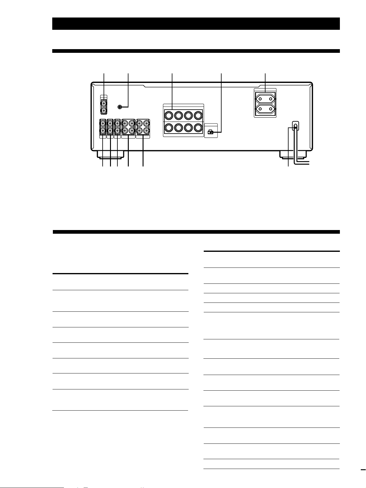
Informações adicionais
Descrição do painel posterior
3 51
PHONO
SIGNAL
IN
L
R
L
R
GND
y
IN
REC OUT IN
REC OUT IN
TAPE1/DAT
TAPE2/MD
AUXINCDINTUNER
L
R
++––
R
B
A
++––
RL
0!¡ 9 8 7 6
IMPEDANCE USE 4–16Ω
SPEAKERS
A+B USE 8–16Ω
BI WIRE USE 4–16Ω
L
EON CONTROL
IN
42
AC OUTLET
SWITCHED 100W MAX
1 PHONO do gira-discos
2 y (SIGNAL GND)
3 SPEAKERS A/B dos altifalantes A/B
4 EON CONTROL IN terminal da função EON
5 AC OUTLET tomadas CA (exceto no TA-FB920R
(modelo do R.U.))
Descrição dos botões do telecomando
Pode utilizar o telecomando para controlar outros
componentes áudio Sony que tenham a marca g
(sensor de telecomando).
Botão(ões)
FUNCTION
CD
TUNER
PHONO
TAPE1/DAT
TAPE2/MD
AUX
TUNER
PRESET +/–
Sony Corporation Printed in Malaysia
P
12
Para a
operação do
Amplificador
Amplificador
Amplificador
Amplificador
Amplificador
Amplificador
Sintonizador
Função
Selecciona o sinal de
entrada das tomadas CD
Selecciona o sinal de entrada
das tomadas TUNER
Selecciona o sinal de entrada
das tomadas PHONO
Selecciona o sinal de entrada
das tomadas TAPE1/DAT
Selecciona o sinal de entrada
das tomadas TAPE2/MD
Selecciona o sinal de entrada
das tomadas AUX
Pesquisa e selecciona
estações programadas
6 Cabo de alimentação CA
7 TAPE1/DAT do deck de cassetes 1/deck DAT
8 TAPE2/MD do deck de cassetes 2/deck de MiniDisc
9 AUX da fonte auxiliar
!º CD do leitor de CDs
!¡ TUNER do sintonizador
Botão(ões)
Para a
Função
operação do
CD
·
P
p
=/+
D.SKIP Troca de disco (para leitor
MD
·
P
p
=/+
TAPE DECK A/B
ª/·
p
0/) Avança rapidamente ou
VOL +/– Amplifier Ajusta o volume
*Automatic Music Sensor / sensor automático de música
Leitor de CDs
Leitor de CDs
Leitor de CDs
Leitor de CDs
Leitor de CDs
Deck de
MiniDisc
Deck de
MiniDisc
Deck de
MiniDisc
Deck de
MiniDisc
Deck de cassetes
A ou B
Deck de cassetes
A ou B
Deck de cassetes
A ou B
Inicia a reprodução
Interrompe a reprodução
Termina a reprodução
Localiza faixas (AMS*)
de CDs equipado com
“changer” para múltiplos
discos)
Inicia a reprodução
Interrompe a reprodução
Termina a reprodução
Localiza faixas
Inicia a reprodução
Termina todas as operações
na fita
rebobina a fita
 Loading...