

Page 1
Help Guide
MULTI CHANNEL AV RECEIVER
STR-ZA5000ES
Use this Help Guide when you have any questions on how to use the receiver.
By updating your software to the latest version, you can take advantage of the newest functions.
Parts and Controls
Receiver
Front panel (with the front cover attached)
Front panel (without the front cover attached)
Power indicator
Indicators on the display panel
Rear panel
Remote control
Remote control (upper section)
Remote control (lower section)
Preparation
1. Installing speakers
Locations and names of speakers
Installing 5.1.4-channel speaker system using top front and top rear speakers
Installing 7.1.2-channel speaker system using top middle speakers
Installing 7.1.2-channel speaker system using front Dolby Atmos enabled speakers
Installing 7.1.4-channel speaker system using an additional stereo power amplifier
Installing 7.1-channel speaker system with Zone 2 connection
Speaker configuration and speaker pattern settings
2. Connecting speakers
Connecting 5.1.4-channel speaker system using top front and top rear speakers
Connecting 7.1.2-channel speaker system using top middle speakers
Connecting 7.1.2-channel speaker system using front Dolby Atmos enabled speakers
1
Page 2
Connecting 7.1.4-channel speaker system using an additional stereo power amplifier
Connecting 7.1-channel speaker system with Zone 2 connection
Speaker patterns and terminals to be connected
3. Connecting a TV
Connecting a TV
Connecting a 4K TV
Connecting a 4K TV that supports HDCP 2.2 and a 4K streaming box using a 4K-compatible HDMI cable
Notes on connecting cables
About HDMI connections
4. Connecting audio-visual devices and the antennas (aerials)
Connecting devices with HDMI jacks
Connecting devices with jacks other than HDMI jacks
Connecting the antennas (aerials)
Connecting another amplifier in Zone 2/3
Digital audio formats supported by the receiver
Notes on connecting cables
About HDMI connections
5. Connecting to the network
Connecting the receiver to the network using LAN cables
6. Turning on the receiver/preparing the remote control
Inserting batteries into the remote control
Turning on the receiver
Notes on installing the receiver
7. Setting up the receiver using Easy Setup
Setting up the receiver using the Easy Setup
Performing Auto Calibration
1. About Auto Calibration
2. Before you perform Auto Calibration
3. Connecting the optimizer microphone
4. Selecting the front speakers
5. Performing Auto Calibration
6. Checking Auto Calibration results
Enjoying Video and Sound
Playing AV devices
Using the menu on the TV screen
Enjoying video/sound from the connected device
Enjoying sound of an ARC compatible TV (Audio Return Channel)
If you use a TV compatible with Dolby Digital Plus output
Watching HDCP 2.2 copyright-protected content
Listening to the radio
Listening to FM/AM radio
2
Page 3
Presetting FM/AM radio stations (Preset Memory)
Tuning to a station directly (Direct Tuning)
Changing the AM tuning scale
Enjoying sound effects
Selecting a sound field (Sound Field)
Resetting sound fields to the default settings
Adjusting the equalizer (Equalizer)
Enjoying clear and dynamic sound at a low volume (Sound Optimizer)
Enjoying more natural sound with speakers installed in the ceiling (In-Ceiling Speaker Mode)
Enjoying high-fidelity sound (Pure Direct)
Using the DTS:X Dialog Control function
Changing the IMAX Mode setting for IMAX Enhanced content playback (IMAX MODE)
Adjusting the crossover frequency settings for IMAX Enhanced content playback (IMAX ADJUSTMENT)
Setting the level of the subwoofer for IMAX Enhanced content playback (SUBWOOFER VOLUME)
Activating the IMAX DTS:X Subwoofer Redirect setting (REDIRECT TO SUBWOOFER)
Using the Multi-Zone Features
Overview of multi-zone features
What you can do with multi-zone features
Available input sources for each zone
Enjoying sound from speakers located in other rooms
Connecting 7.1-channel speaker system with Zone 2 connection
Assigning the speakers for Zone 2
Enjoying sound in Zone 2
Enjoying sound from speakers located in other rooms using another amplifier
Connecting another amplifier in Zone 2/3
Setting the volume control for Zone 2/3 (Zone2/3 Line Out)
Setting the Zone 2 HDMI audio output of connected devices (Zone2 Audio Out)
Setting the priority for the main zone (Priority)
Enjoying sound using another amplifier in Zone 2 and/or Zone 3
Using Other Features
Interlocking with BRAVIA TV and other devices (“BRAVIA” Sync)
What is “BRAVIA” Sync?
Preparing for “BRAVIA” Sync
Turning off the receiver and connected devices simultaneously with the TV (System Power Off function) (Standby Linked to TV)
Enjoying TV sound from the speakers connected to the receiver (System Audio Control function)
Enjoying an input source from a connected device immediately (One-Touch Play function)
Selecting the optimum picture quality and sound field automatically (Scene Select function)
About Home Theatre Control function
Operating the receiver menu using the TV remote control (Remote Easy Control function)
Echo Canceling function
About Language Follow function
3
Page 4
Enjoying video and sound with your desired way of use
Switching the monitors that output the HDMI video signals
Switching between digital and analog audio (Input Mode)
Using other video/audio input jacks (Input Assign)
Saving and recalling various settings for the receiver (Custom Preset)
About Custom Preset
Saving the settings to a preset
Recalling the settings saved to the scene
Items for which you can save settings and the default values for each item
Using the sleep timer
Using the sleep timer (Sleep)
Checking information on the receiver
Viewing information on the display panel
Adjusting Settings
Easy Setup
Setting up the receiver using the Easy Setup
Input Setup
Changing the assignment and display for the input jacks
Changing the name for each input (Name)
Speaker Setup
1. About Auto Calibration
2. Before you perform Auto Calibration
3. Connecting the optimizer microphone
4. Selecting the front speakers
5. Performing Auto Calibration
6. Checking Auto Calibration results
Calibrating the phase characteristics of the speakers (Automatic Phase Matching)
Selecting the Auto Calibration type (Calibration Type)
Checking the speaker position and the corresponding speaker terminals (Speaker Connections)
Selecting the speaker pattern (Speaker Pattern)
Assigning the surround back speaker terminals (SB Speaker Assign)
Assigning the height1 speaker terminals (Height1 SP Assign)
Adjusting the speaker size (Size)
Adjusting the speaker distance (Distance)
Adjusting the speaker level (Level)
Outputting a test tone from each speaker (Test Tone)
Setting the crossover frequency of the speakers (Crossover Frequency)
Adjusting the equalizer (Equalizer)
Lifting up the sound of the center speaker (Center Speaker Lift Up)
Setting the correct angles of the surround speakers (Surround Speaker Position)
Calibrating speaker positioning (Speaker Relocation)
Setting the height from the floor to the ceiling speakers (Ceiling Height)
4
Page 5
Selecting the speaker impedance (Speaker Impedance)
Selecting the unit of measurement (Distance Unit)
Network Setup
Setting up a network (Internet Setup)
Checking the network information (Information)
Enabling the network function even when this receiver is in standby mode (Network Standby)
Enjoying Hi-Fi System sound (Music Connect)
Audio Setup
Playing audio signals with high-quality sound (Digital Legato Linear (D.L.L.))
Enjoying clear and dynamic sound at a low volume (Sound Optimizer)
Selecting a sound field (Sound Field)
Enjoying more natural sound with speakers installed in the ceiling (In-Ceiling Speaker Mode)
Enjoying high-fidelity sound (Pure Direct)
Setting the low-pass filter for the subwoofer output (Subwoofer Low Pass Filter)
Synchronizing audio with video output (A/V Sync)
Selecting the language of digital broadcasts (Dual Mono)
Compressing the dynamic range (Dynamic Range Compressor)
Switching the mode of the DTS decoder (Neural:X)
HDMI Setup
Up-converting video signals to 4K (4K Scaling)
Controlling HDMI devices (Control for HDMI)
Turning off the receiver and connected devices simultaneously with the TV (System Power Off function) (Standby Linked to TV)
Enjoying sound of an ARC compatible TV (Audio Return Channel)
Enjoying content of a connected device without turning on the receiver (Pass Through)
Setting the HDMI audio signal output of connected devices (Audio Out)
Setting the Zone 2 HDMI audio output of connected devices (Zone2 Audio Out)
Setting the level of the subwoofer (Subwoofer Level)
Selecting the method to use the HDMI OUT B (ZONE 2) jack (HDMI Out B Mode)
Setting the priority for the main zone (Priority)
Speeding up the display when switching the HDMI input (Fast View)
Setting HDMI signal formats (HDMI Signal Format)
Zone Setup
Setting up the receiver to enjoy sound in Zone 2/3 (Zone Controls)
Presetting the volume in the main zone (Main Preset Volume)
Limiting the volume for the main zone (Main Max Volume)
Presetting the volume in Zone 2/3 (Zone2/3 Preset Volume)
Limiting the volume for Zone 2/3 (Zone2/3 Max Volume)
Setting the volume control for Zone 2/3 (Zone2/3 Line Out)
System Setup
Selecting the language (Language)
Tuning on/off the display for the volume level or sound field (Auto Display)
Setting standby mode (Auto Standby)
5
Page 6
Changing the volume display (Volume Display)
Switching the brightness of the display panel (Dimmer)
Using the sleep timer (Sleep)
Checking the software version (Software Version)
Updating the software via the network (Network Update)
Updating the software using the USB flash drive (USB Update)
Setting the tuner (Tuner Setup)
Install Setup
Turning on control mode for maintenance (External Control)
Switching on/off the 12V trigger output (Trigger Out 1/2/3)
Displaying a test screen (Test Picture for HDMI Out A/B)
Locking settings of the receiver (Settings Lock)
Using the menu on the display panel
Operating the receiver with the menu on the display panel
Viewing information on the display panel
Reverting to the factory default settings
Reverting to the factory default settings
Troubleshooting
Error messages
PROTECTOR
UPDATE FAILED
FAN STOPPED
List of messages after Auto Calibration measurements
Network features message list
General
The receiver is turned off automatically.
The receiver does not turn on after performing USB Update or Network Update.
The receiver does not turn on even when the TV is turned on.
The receiver turns off when the TV is turned off.
The receiver does not turn off even when the TV is turned off.
Image
No image appears on the TV screen.
No 3D content appears on the TV screen.
No 4K content appears on the TV screen.
No image is output to the TV screen when the receiver is in standby mode.
HDR (High Dynamic Range) images cannot be displayed in HDR mode.
The home menu does not appear on the TV screen.
The display panel is turned off.
Image does not appear on the TV screen when the receiver is not turned on.
When the language for the on-screen display of the TV is changed, the on-screen display language of the receiver is changed simultaneously.
Sound
6
Page 7
4-587-297-12(5) Copyright 2016 Sony Corporation
No sound or only a very low level of sound is heard, no matter which device is selected.
There is severe humming or noise.
No sound or only a very low level of sound is heard from specific speakers.
There is no sound from a specific device.
There is no sound from the TV via the HDMI OUT A jack when using the Audio Return Channel function.
The Dolby Atmos-compatible sound played back on the TV is not output from the receiver.
The left and right sound is unbalanced or reversed.
Dolby Digital or DTS multi-channel sound is not reproduced.
The surround effect cannot be obtained.
A test tone is not output from the speakers.
A test tone is output from a different speaker than the speaker displayed on the TV screen.
No sound is output from the TV when the receiver is in standby mode.
Tuner
The FM reception is poor.
The FM stereo reception is poor.
You cannot tune to radio stations.
USB devices
A USB device is not recognized.
A USB device cannot be connected to the USB port.
Network connection
An error message appears.
Cannot connect to the network.
“BRAVIA” Sync (Control for HDMI)
The Control for HDMI function does not work.
TV sound cannot be heard from the speakers connected to the receiver.
Remote control
The remote control does not function.
If the problem is not solved
Reverting to the factory default settings
Resetting sound fields to the default settings
Customer support websites
Other Information
Trademarks
Trademarks
Software License Information
Software License Information
7
Page 8

Help Guide
MULTI CHANNEL AV RECEIVER
STR-ZA5000ES
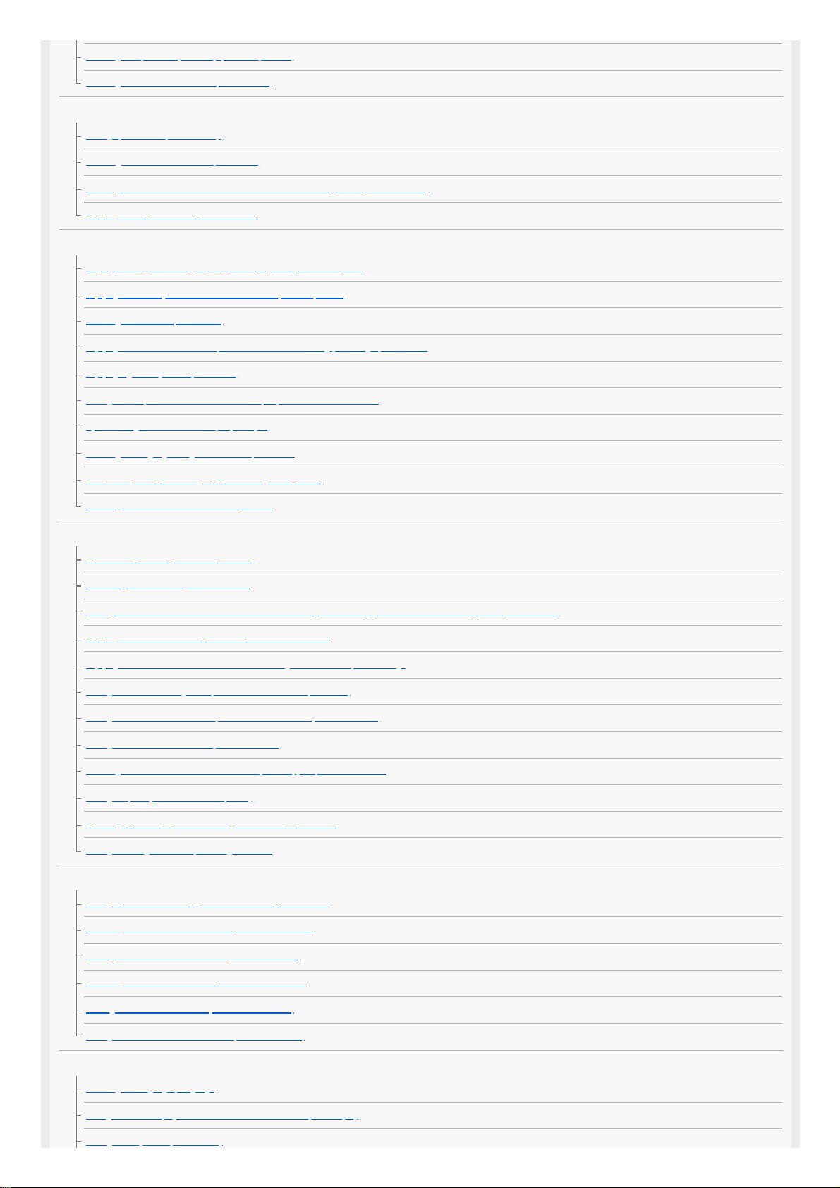
Front panel (with the front cover attached)
Related Topic
Front panel (without the front cover attached)
Indicators on the display panel
Power indicator
4-587-297-12(5) Copyright 2016 Sony Corporation
(power)
Turns the receiver on or sets it to standby mode. The indicator lights up according to the status of the receiver. Also, the color of the indicator changes depending on
the status of the receiver.
1.
Remote sensor
Receives signals from remote control.
2.
MASTER VOLUME
Turns to adjust the volume level.
3.
HDMI jack cover
Open the cover when you use HDMI IN 6 (GAME) jack.
4.
8
Page 9
Help Guide
MULTI CHANNEL AV RECEIVER
STR-ZA5000ES
Front panel (without the front cover attached)
Fixing point of the front cover
Attaches the front cover using this fixing point.
1.
PING
Displays the IP address and MAC address on the display panel.
2.
Input buttons
Select the device you want to use.
3.
TONE MODE , TONE+/–
Press to adjust the bass/treble level of the speaker.
4.
SPEAKERS
Select the front speaker system (FRONT A speakers, FRONT B speakers or both FRONT A and FRONT B speakers) or turn off the speaker output.
5.
AUTO CAL MIC jack
Connect the supplied optimizer microphone for Auto Calibration to this jack.
6.
HDMI OUT
Switches the output for two monitors connected to the HDMI OUT A and HDMI OUT B (ZONE 2) jacks.
7.
SETTING
(USB) port
Used for maintenance and service.
8.
ZONE CONTROL (ZONE2, ZONE3)
Selects the place where you will control.
9.
MEMORY
Press to store a station during tuner operation.
10.
CUSTOM PRESET (1, 2, 3, 4)
Saves and recalls various settings for the receiver.
11.
TUNING MODE, TUNING +/–
Press to operate a tuner (FM/AM).
12.
DISPLAY
Displays information on the display panel.
13.
RETURN
Returns to the previous menu.
14.
HOME
Displays the home menu on the TV screen.
15.
ENTER,
/ / /
Press / / / to select the menu items. Then press ENTER to enter the selection.
16.
OPTIONS
Displays and selects items from the options menus.
17.
AMP MENU
Displays the menu on the display panel of the receiver to operate the receiver.
18.
IN-CEILING SP
Activates the In-Ceiling Speaker Mode.
19.
SOUND FIELD (2CH/DIRECT, A.F.D., MOVIE, MULTI ST.)20.
9
Page 10

Related Topic
Front panel (with the front cover attached)
Indicators on the display panel
Power indicator
4-587-297-12(5) Copyright 2016 Sony Corporation
Selects the sound field you want.
HDMI IN 6 (GAME) jack
Connect to a video game console. The video and sound from your video game console is input.
21.
10
Page 11

Help Guide
MULTI CHANNEL AV RECEIVER
STR-ZA5000ES
Power indicator
Green: The receiver is turned on.
Amber: The receiver is in standby mode, and:
[Control for HDMI] or [Network Standby] is set to [On].
[Pass Through] is set to [On] or [Auto].
[Zone2 Power] or [Zone3 Power] is set to [On].
The indicator turns off when the receiver is in standby mode and [Control for HDMI], [Pass Through], [Network Standby], [Zone2 Power] and [Zone3 Power] are set
to [Off].
The top of the cabinet may become hot. This is because part of the circuit(s) inside the receiver is(are) still turned on, and is not a malfunction.
Note
The indicator flashes slowly when a software update is in progress.
4-587-297-12(5) Copyright 2016 Sony Corporation
11
Page 12
Help Guide
MULTI CHANNEL AV RECEIVER
STR-ZA5000ES
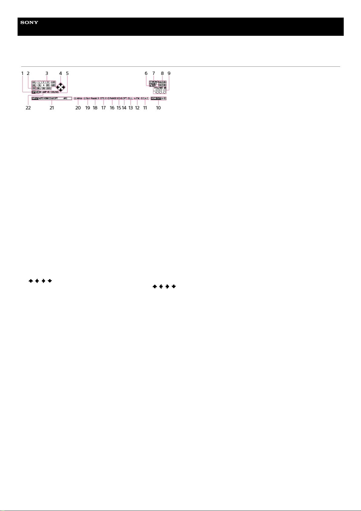
Indicators on the display panel
Speaker system indicator1.
SW
Lights up when subwoofer(s) is (are) connected and the audio signal is output from the PRE OUT SUBWOOFER jack(s).
2.
Playback channel indicator
Indicates the speaker that is designated to output sound. Shows how the receiver down-mixes or up-mixes the source sound, based on the speaker settings.
L
Front Left
R
Front Right
C
Center
SL
Surround Left
SR
Surround Right
SBL
Surround Back Left
SBR
Surround Back Right
H1L
Height1 Left
H1R
Height1 Right
H2L
Height2 Left
H2R
Height2 Right
3.
/ / /
Indicates currently available operation on the display panel using / / / on the remote control.
4.
IN-CEILING
Lights up when the In-Ceiling Speaker Mode is activated.
5.
SLEEP
Lights up when the sleep timer is activated.
6.
Tuning indicator
Lights up when the receiver tunes to a radio station.
ST
The receiver tunes to a stereo broadcast.
MONO
FM receiving mode is set to the mono mode.
PRESET
The tuning mode is set to the preset mode.
7.
ZONE2, ZONE3
The applicable indicator lights up while [Zone2 Power] or [Zone3 Power] is set to [On].
8.
VOLUME
Displays the current volume.
9.
HDMI OUT A+B10.
D.C.A.C.
Lights up when the measurement results of the Auto Calibration function are applied.
11.
A.P.M.
Lights up when the A.P.M. (Automatic Phase Matching) function is activated. You can only set the A.P.M. function in the D.C.A.C. (Digital Cinema Auto Calibration)
function.
12.
D.L.L.
Lights up when the Digital Legato Linear (D.L.L.) function is activated.
13.
S.OPT.
Lights up when the Sound Optimizer function is activated.
14.
12
Page 13

4-587-297-12(5) Copyright 2016 Sony Corporation
EQ
Lights up when the equalizer is activated.
15.
D.RANGE
Lights up when dynamic range compression is activated.
16.
DTS:X
Lights up when DTS:X decoding is activated.
17.
Neural:X
Lights up when DTS Neural:X decoding is activated.
18.
Surr
Lights up when Dolby Surround decoding is activated.
19.
Atmos
Lights up when Dolby Atmos decoding is activated.
20.
Input indicator
Lights up to indicate the current input.
AUTO
[Input Mode] is set to [Auto].
HDMI
The receiver recognizes devices connected via an HDMI IN jack.
COAX
Digital signals are input through the COAXIAL jack.
OPT
Digital signals are input through the OPTICAL jack.
ARC
TV input is selected and Audio Return Channel (ARC) signals are detected.
21.
BI-AMP
Lights up when [SB Speaker Assign] in the [Speaker Setup] menu is set to [Bi-Amp] to use a bi-amplifier connection.
22.
13
Page 14
Help Guide
MULTI CHANNEL AV RECEIVER
STR-ZA5000ES
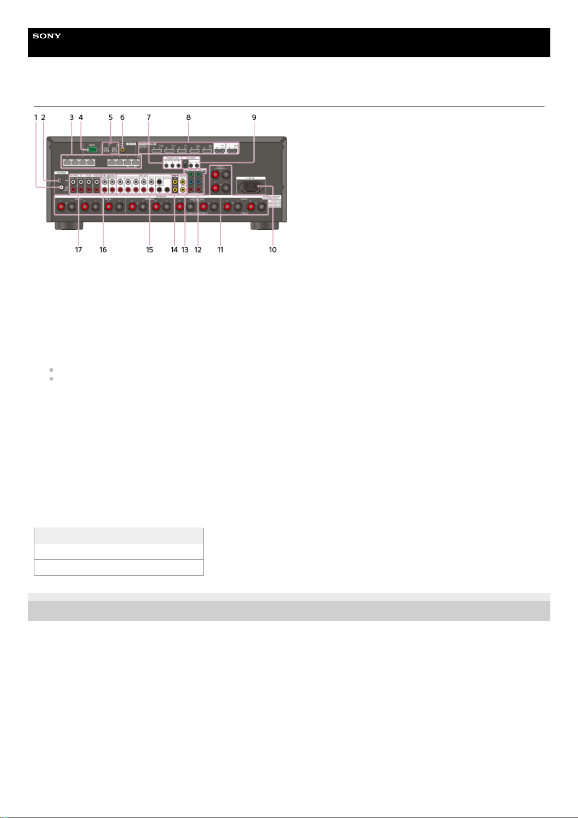
Rear panel
4-587-297-12(5) Copyright 2016 Sony Corporation
FM ANTENNA terminal1.
AM ANTENNA terminal2.
Giga-bit Ethernet hub (*1)3.
RS232C port (*1)4.
DIGITAL OPTICAL IN jacks5.
DIGITAL COAXIAL IN jack6.
TRIGGER OUT jacks
Connect to interlock on/off of the power supply of other 12V TRIGGER compliant equipment, or the amplifier/receiver of Zone 2 or Zone 3.
7.
HDMI IN/OUT (*2) (*3) jacks8.
IR REMOTE IN/OUT jacks
You can control the receiver from a distance by connecting an IR repeater (not supplied) to the IR REMOTE IN jack.
You can start or stop playback of devices such as a CD player connected to the receiver by connecting an IR Blaster (not supplied) to the IR REMOTE OUT jack.
9.
AC IN terminal
Connect the supplied AC power cord (mains lead).
10.
SPEAKERS terminals11.
COMPONENT VIDEO IN jacks12.
VIDEO OUT (*3) jacks13.
VIDEO IN jacks14.
PRE OUT jacks
Connect to an external power amplifier and a subwoofer.
15.
ZONE 2/ZONE 3 AUDIO OUT jacks16.
AUDIO IN jacks17.
These are control expansion terminals for custom installation.
*1
HDCP 2.2 is newly enhanced copyright protection technology that is used to protect content such as 4K movies.
*2
Connect a TV to the corresponding output jacks to watch video input from these jacks. For details, see “Connecting a TV.”
*3
Input jack Output jack
HDMI IN HDMI OUT A or HDMI OUT B (ZONE 2)
VIDEO IN MONITOR VIDEO OUT
14
Page 15
Help Guide
MULTI CHANNEL AV RECEIVER
STR-ZA5000ES
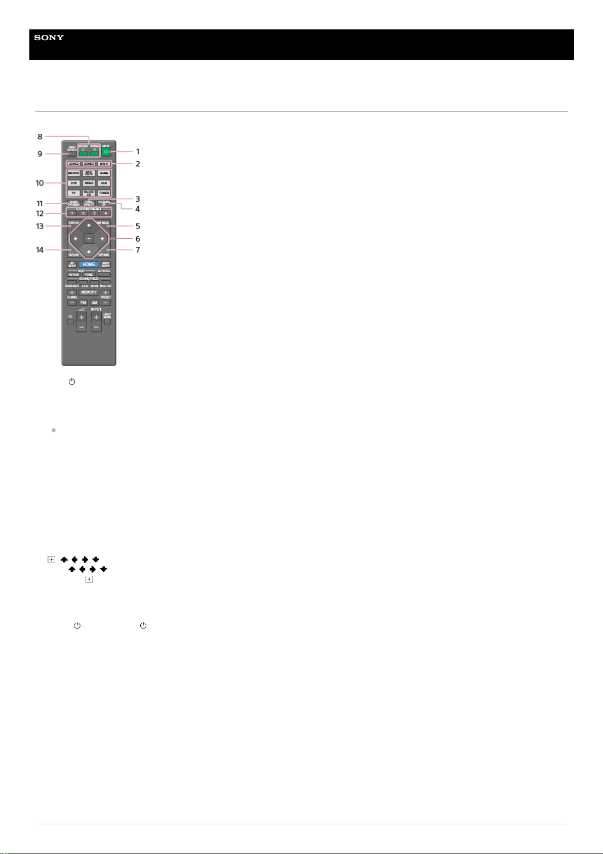
Remote control (upper section)
Use the supplied remote control to operate this receiver.
MAIN (power)
Turns the receiver on or sets it to the standby mode.
Saving power in standby mode
Save power by setting the receiver as follows:
Set [Control for HDMI], [Pass Through], [Network Standby], [Zone2 Power] and [Zone3 Power] to [Off].
1.
ZONE2, ZONE3, MAIN
Selects the place where you will control.
2.
PURE DIRECT
Press to use the Pure Direct function.
3.
IN-CEILING SP
Activates the In-Ceiling Speaker Mode.
4.
AMP MENU
Displays the menu on the display panel of the receiver to operate the receiver.
5.
, / / /
Press / / / to select the menu items.
Then press
to enter the selection.
6.
OPTIONS
Displays the options menus on the TV screen for item selection.
7.
ZONE2
(power), ZONE3 (power)
Turns the receiver in Zone 2 or Zone 3 on or sets it to the standby mode.
8.
HDMI OUTPUT
Switches the output for two monitors connected to the HDMI OUT A and HDMI OUT B (ZONE 2) jacks.
9.
Input buttons
Select the device you want to use.
When you press any of the input buttons, the receiver turns on.
10.
SOUND OPTIMIZER
Press to use the Sound Optimizer function to enjoy clear and dynamic sound at low volume levels.
11.
CUSTOM PRESET (1, 2, 3, 4)
Saves and recalls various settings for the receiver.
12.
DISPLAY
Displays information on the TV screen.
13.
RETURN
Returns to the previous menu.
14.
15
Page 16

Note
The above explanations are intended to serve as examples.
Related Topic
Remote control (lower section)
4-587-297-12(5) Copyright 2016 Sony Corporation
16
Page 17
Help Guide
MULTI CHANNEL AV RECEIVER
STR-ZA5000ES
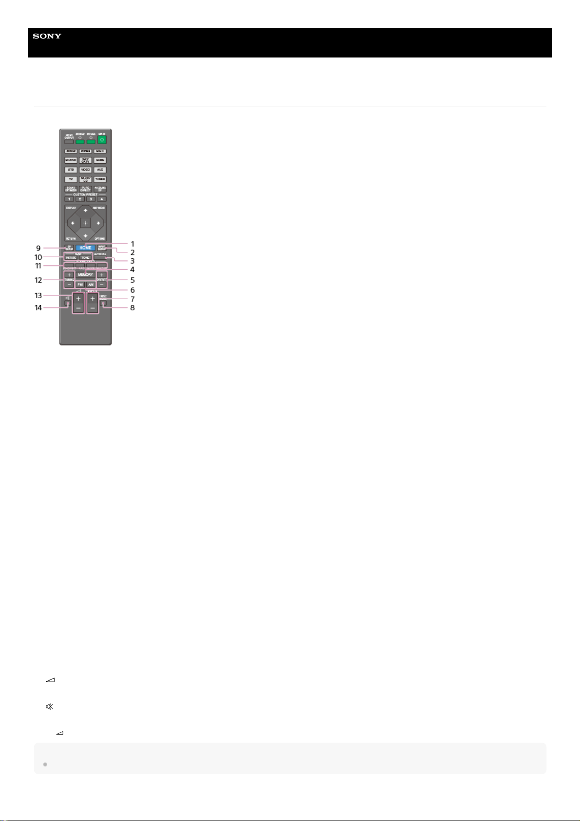
Remote control (lower section)
Use the supplied remote control to operate this receiver.
Note
The above explanations are intended to serve as examples.
HOME
Displays the home menu on the TV screen.
1.
INPUT SETUP
Displays the [Input Setup] menu.
2.
AUTO CAL
Displays the auto calibration menu on the display panel of the receiver to perform Auto Calibration.
3.
MEMORY
Press to enter the memory mode of the tuner.
4.
PRESET +/–
Press to select the preset stations.
5.
FM/AM
Press to select the band you want.
6.
INPUT +/–
Press to select the input source.
7.
INPUT MODE
Press to select the input mode.
8.
SP SETUP
Displays the [Speaker Setup] menu.
9.
TEST (PICTURE, TONE)
Press to output the test picture or test tone.
10.
SOUND FIELD (2CH/DIRECT, A.F.D., MOVIE, MULTI ST.)
Selects the sound field you want.
11.
TUNING +/–
Press to select a station.
12.
+ (*)/-
Adjust the volume level.
13.
Turns off the sound temporarily. Press the button again to restore the sound.
14.
The
+ button has tactile dot. Use the tactile dot as a reference when operating the receiver.
*
17
Page 18

Related Topic
Remote control (upper section)
4-587-297-12(5) Copyright 2016 Sony Corporation
18
Page 19
Help Guide
MULTI CHANNEL AV RECEIVER
STR-ZA5000ES
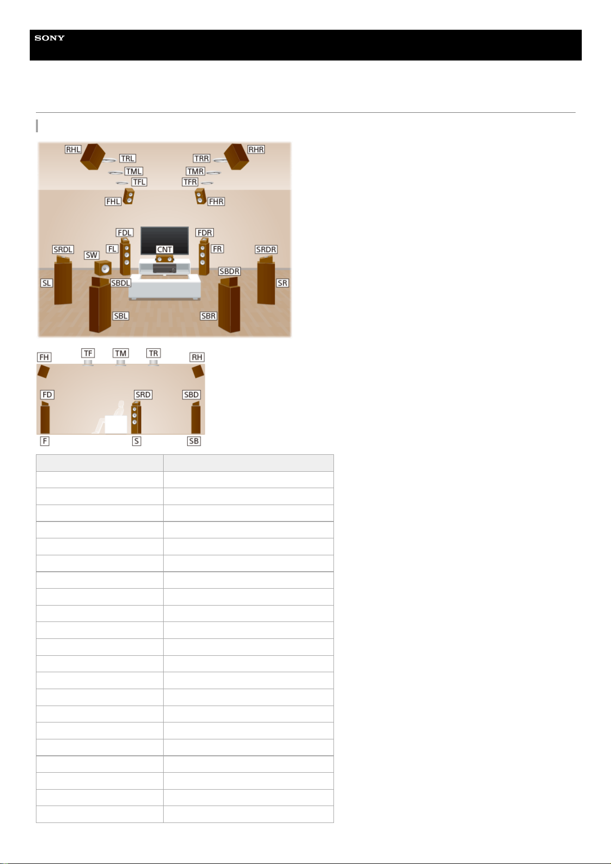
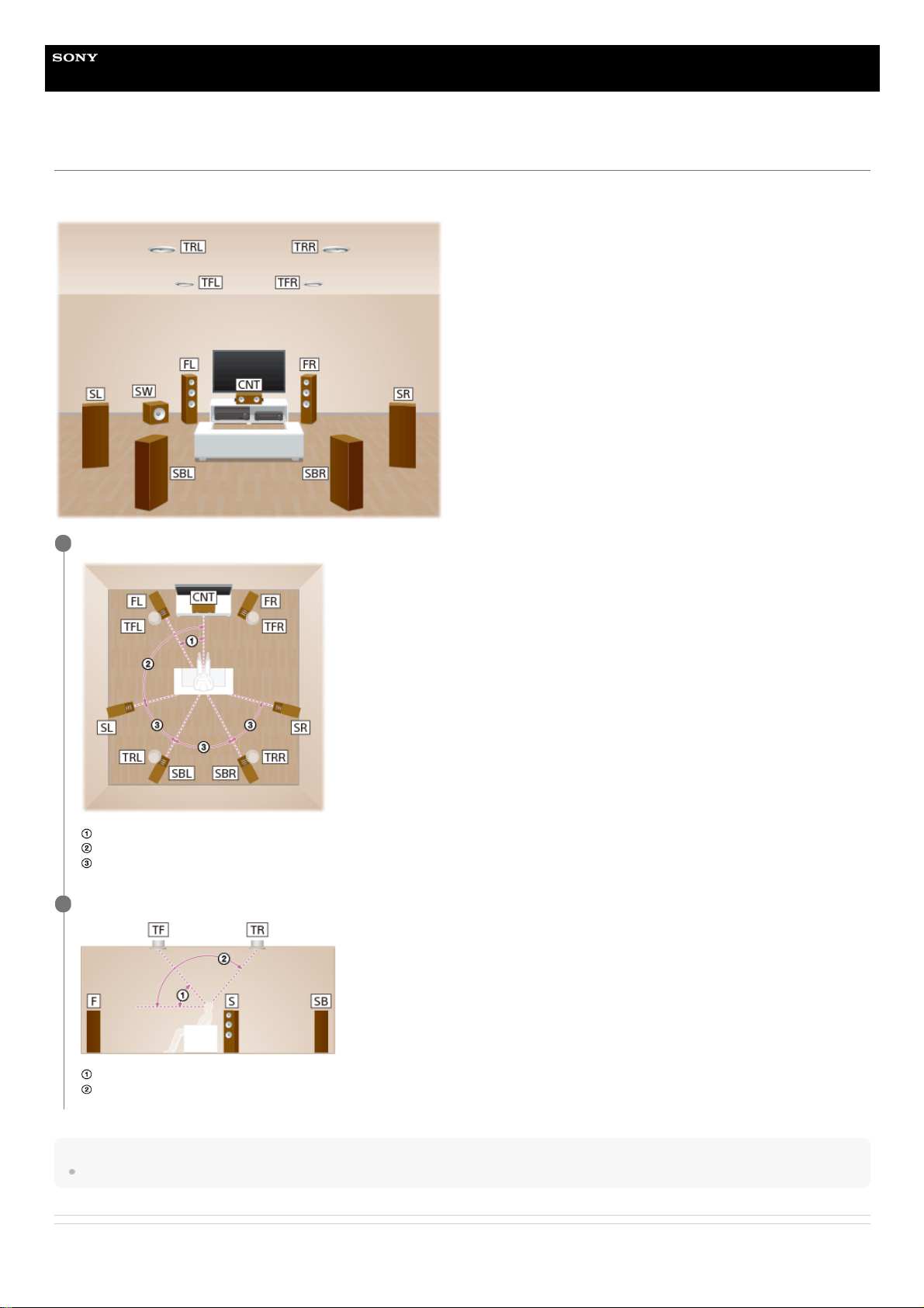
Locations and names of speakers
Location of each speaker
Abbreviations used in illustrations Speaker name
FL Front left speaker
FR Front right speaker
CNT Center speaker
SL Surround left speaker
SR Surround right speaker
SBL Surround back left speaker
SBR Surround back right speaker
SB Surround back speaker
SW Subwoofer
TFL Top front left speaker
TFR Top front right speaker
TML Top middle left speaker
TMR Top middle right speaker
TRL Top rear left speaker
TRR Top rear right speaker
FHL Front high left speaker
FHR Front high right speaker
RHL Rear high left speaker
RHR Rear high right speaker
FDL Front Dolby Atmos enabled left speaker
FDR Front Dolby Atmos enabled right speaker
19
Page 20

4-587-297-12(5) Copyright 2016 Sony Corporation
Abbreviations used in illustrations Speaker name
SDL Surround Dolby Atmos enabled left speaker
SDR Surround Dolby Atmos enabled right speaker
SBDL Surround back Dolby Atmos enabled left speaker
SBDR Surround back Dolby Atmos enabled right speaker
Z2L Zone 2 left speaker
Z2R Zone 2 right speaker
Z3L Zone 3 left speaker
Z3R Zone 3 right speaker
20
Page 21
Help Guide
MULTI CHANNEL AV RECEIVER
STR-ZA5000ES
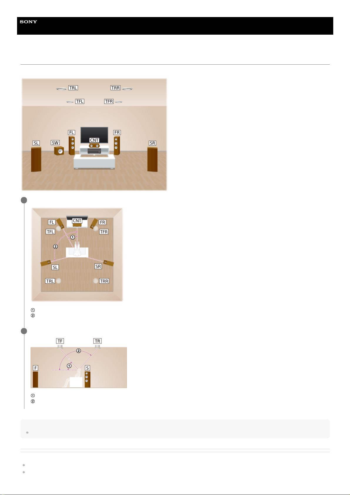
Installing 5.1.4-channel speaker system using top front and top rear speakers
This speaker installation is configured by adding top front speakers and top rear speakers to standard 5.1-channel speaker system placed on the listener-level.
Hint
As the subwoofer does not emit highly directional signals, you can place it wherever you want.
Related Topic
Locations and names of speakers
Connecting 5.1.4-channel speaker system using top front and top rear speakers
Place the speakers on the listener-level at the angles shown below.
30°
100° - 120°
1
Install the overhead (top) speakers at the angles shown below.
30° - 55°
125° - 150°
2
21
Page 22

4-587-297-12(5) Copyright 2016 Sony Corporation
22
Page 23
Help Guide
MULTI CHANNEL AV RECEIVER
STR-ZA5000ES
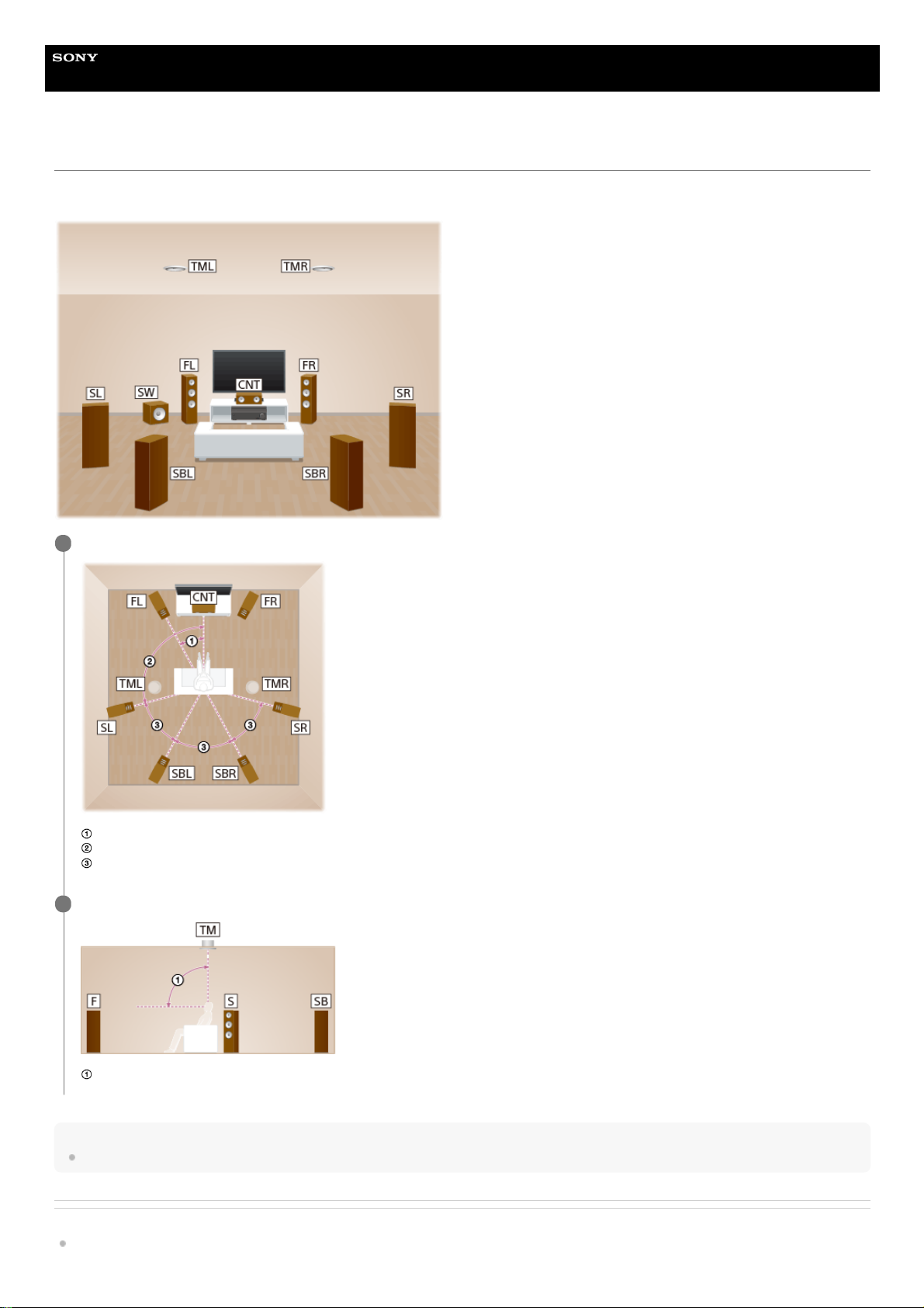
Installing 7.1.2-channel speaker system using top middle speakers
This speaker installation is configured by adding top middle speakers to 7.1-channel speaker system consisting of standard 5.1-channel speaker system and additional
surround back speakers placed on the listener-level.
Hint
As the subwoofer does not emit highly directional signals, you can place it wherever you want.
Related Topic
Locations and names of speakers
Place the speakers on the listener-level at the angles shown below.
30°
100° - 120°
Same angle
1
Install the overhead (top) speakers at the angles shown below.
65° - 100°
2
23
Page 24

Connecting 7.1.2-channel speaker system using top middle speakers
4-587-297-12(5) Copyright 2016 Sony Corporation
24
Page 25
Help Guide
MULTI CHANNEL AV RECEIVER
STR-ZA5000ES
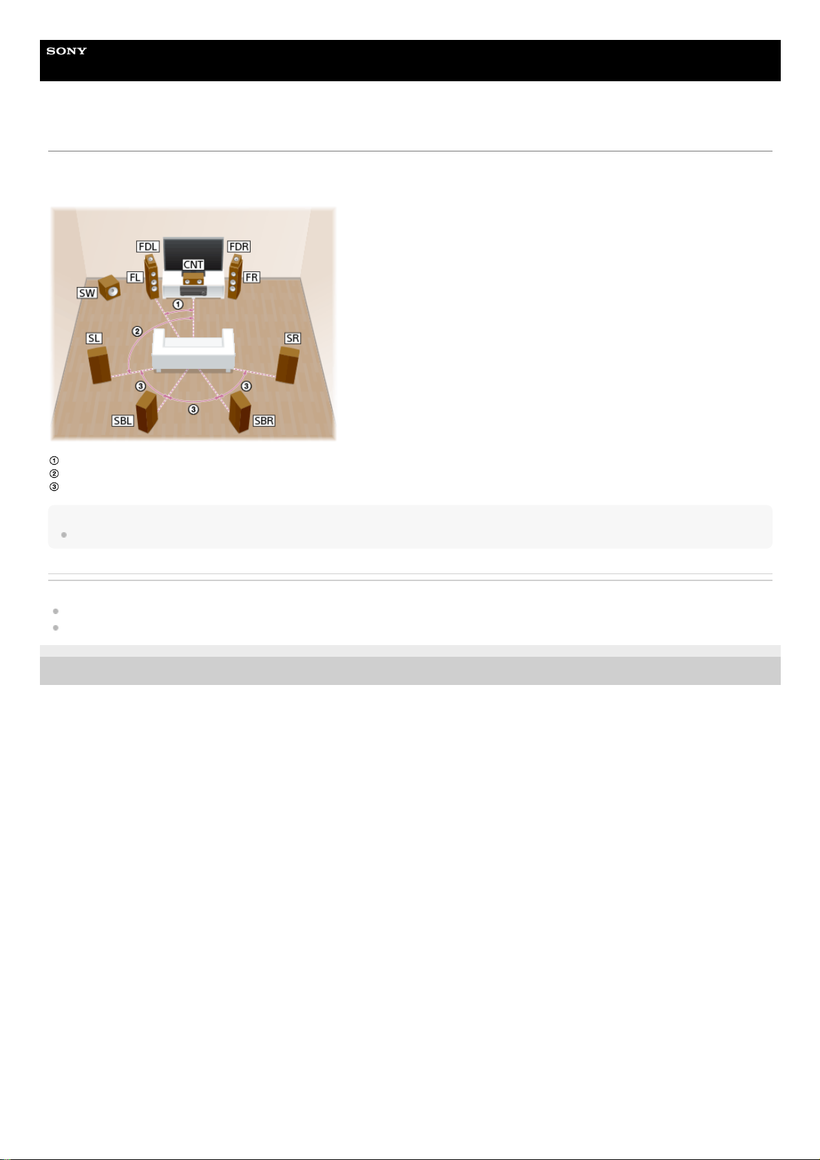
Installing 7.1.2-channel speaker system using front Dolby Atmos enabled speakers
This speaker installation is configured by adding front Dolby Atmos enabled speakers (*) to 7.1-channel speaker system consisting of standard 5.1-channel speaker
system and additional surround back speakers placed on the listener-level.
30°
100° - 120°
Same angle
Hint
As the subwoofer does not emit highly directional signals, you can place it wherever you want.
Related Topic
Locations and names of speakers
Connecting 7.1.2-channel speaker system using front Dolby Atmos enabled speakers
4-587-297-12(5) Copyright 2016 Sony Corporation
You can enjoy the exciting and powerful sound of the Dolby Atmos 3D content without installing overhead (top) speakers by using Dolby Atmos enabled speakers which reflect off the ceiling.
*
25
Page 26
Help Guide
MULTI CHANNEL AV RECEIVER
STR-ZA5000ES
Installing 7.1.4-channel speaker system using an additional stereo power amplifier
This speaker installation is configured by adding top front speakers and top rear speakers to 7.1-channel speaker system consisting of standard 5.1-channel speaker
system and additional surround back speakers placed on the listener-level. An additional stereo power amplifier is used for the top rear speakers.
Hint
As the subwoofer does not emit highly directional signals, you can place it wherever you want.
Related Topic
Place the speakers on the listener-level at the angles shown below.
30°
100° - 120°
Same angle
1
Install the overhead (top) speakers at the angles shown below.
30° - 55°
125° - 150°
2
26
Page 27

Locations and names of speakers
Connecting 7.1.4-channel speaker system using an additional stereo power amplifier
4-587-297-12(5) Copyright 2016 Sony Corporation
27
Page 28
Help Guide
MULTI CHANNEL AV RECEIVER
STR-ZA5000ES
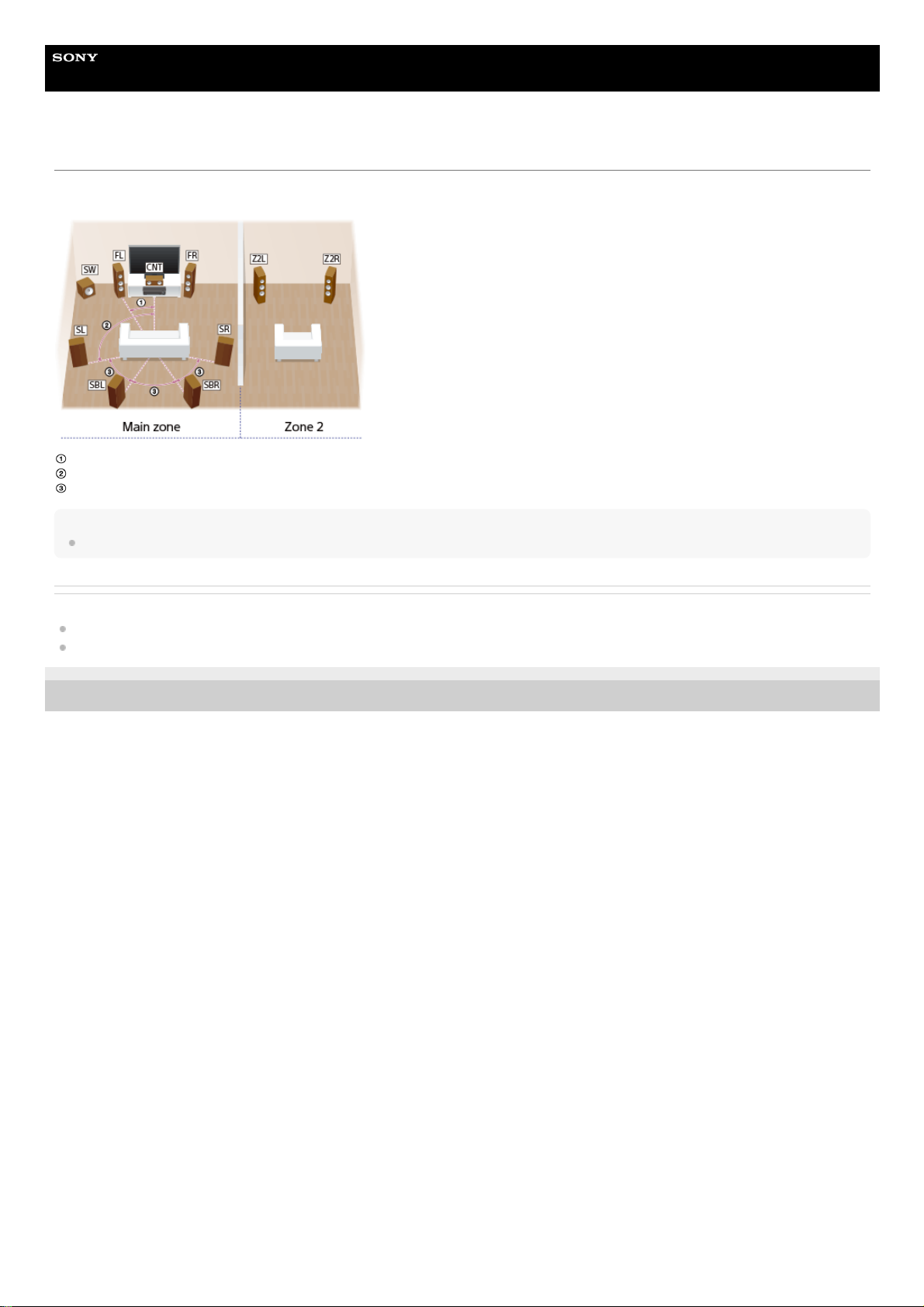
Installing 7.1-channel speaker system with Zone 2 connection
This speaker installation shows configurations in the main zone and Zone 2. In the main zone, 7.1-channel speaker system consisting of standard 5.1-channel speaker
system and additional surround back speakers placed on the listener-level is installed, and another pair of speakers is installed in Zone 2.
30°
100° - 120°
Same angle
Hint
As the subwoofer does not emit highly directional signals, you can place it wherever you want.
Related Topic
Locations and names of speakers
Connecting 7.1-channel speaker system with Zone 2 connection
4-587-297-12(5) Copyright 2016 Sony Corporation
28
Page 29
Help Guide
MULTI CHANNEL AV RECEIVER
STR-ZA5000ES
Speaker configuration and speaker pattern settings
Select the speaker pattern using [Speaker Pattern] in the [Setup] - [Speaker Setup] menu according to the speaker configuration which you are using.
Top front speakers
Top middle speakers
Top rear speakers
Front high speakers
Rear high speakers
Front Dolby Atmos enabled speakers
Surround Dolby Atmos enabled speakers
Surround back Dolby Atmos enabled speakers
Related Topic
Locations and names of speakers
Speaker patterns and terminals to be connected
Selecting the speaker pattern (Speaker Pattern)
Assigning the surround back speaker terminals (SB Speaker Assign)
Assigning the height1 speaker terminals (Height1 SP Assign)
Setting the priority for the main zone (Priority)
4-587-297-12(5) Copyright 2016 Sony Corporation
Speaker configuration in each zone
[SB Speaker
Assign] (*1)
[Height1 SP
Assign] (*2)
Speaker pattern to be selected in
[Speaker Pattern]
Main zone Zone 2
5.1.4-channel speaker system using top front and top rear
speakers
Not
used
[Off] [Off] [5.1.4 (TF+TR)]
7.1.2-channel speaker system using top middle speakers
Not
used
[Off] [Off] [7.1.2 (TM)]
7.1.2-channel speaker system using front Dolby Atmos
enabled speaker
Not
used
[Off] [Off] [7.1.2 (FD)]
7.1.4-channel speaker system using an additional stereo
power amplifier
Not
used
[Off] [Off] [7.1.4 (TF+TR)]
7.1-channel speaker system with Zone 2 connection
2channel
[Off] [Zone2] [7.1]
You can only set [SB Speaker Assign] if the speaker pattern is set to a setting that does not have surround back speakers.
*1
You can only set [Height1 SP Assign] if the speaker pattern is set to a setting that does not have the following speakers:
*2
29
Page 30
Help Guide
MULTI CHANNEL AV RECEIVER
STR-ZA5000ES
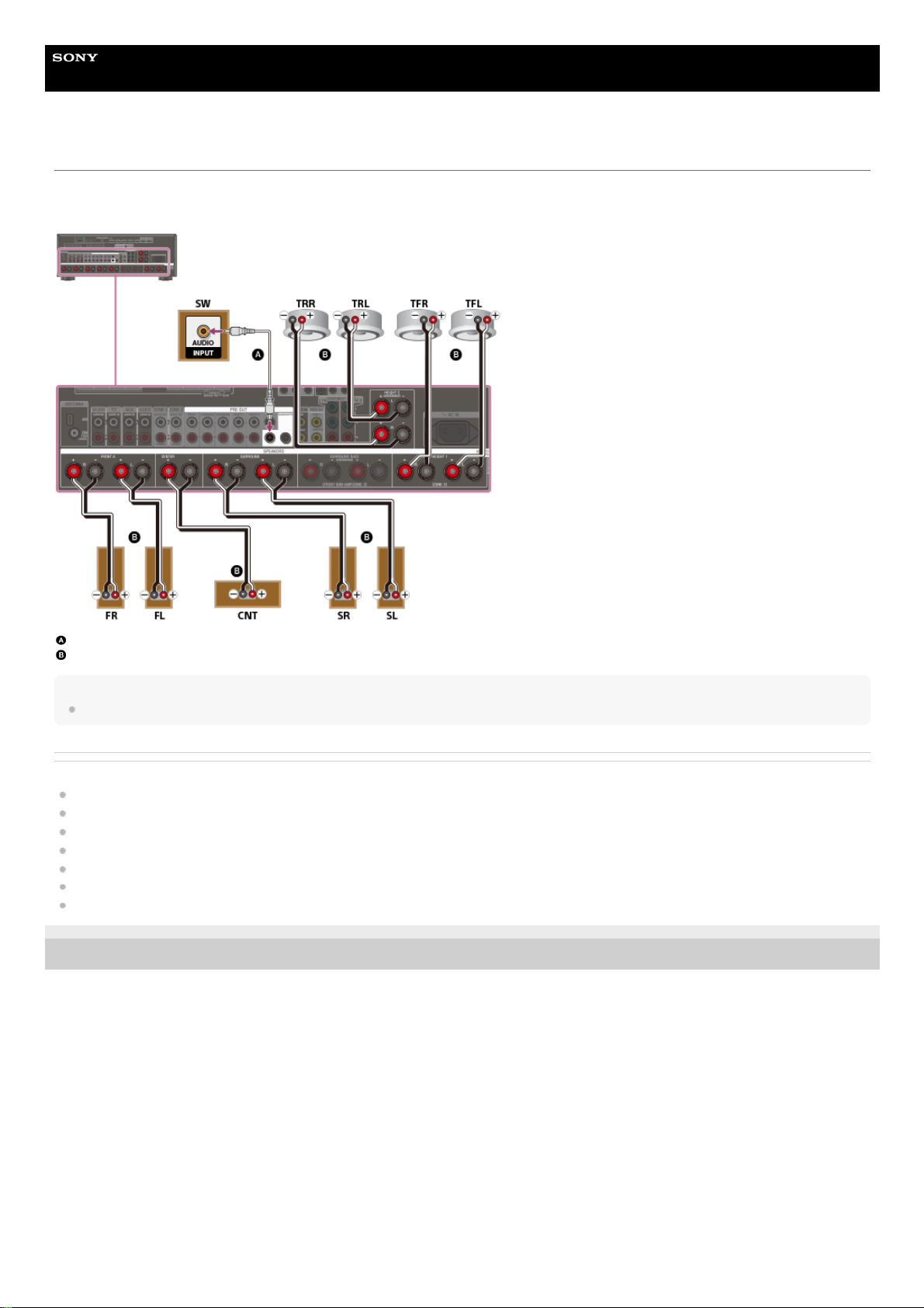
Connecting 5.1.4-channel speaker system using top front and top rear speakers
Connect each speaker as illustrated below.
Before connecting cables, be sure to disconnect the AC power cord (mains lead).
For details on how to connect speaker cables to the receiver, see “How to connect speaker cables.”
Monaural audio cable (not supplied)
Speaker cable (not supplied)
Note
After you have installed and connected your speakers, set the speaker pattern to [5.1.4 (TF+TR)] using [Speaker Pattern] in the [Speaker Setup] menu.
Related Topic
Locations and names of speakers
Installing 5.1.4-channel speaker system using top front and top rear speakers
Speaker configuration and speaker pattern settings
Assigning the surround back speaker terminals (SB Speaker Assign)
Assigning the height1 speaker terminals (Height1 SP Assign)
Selecting the speaker pattern (Speaker Pattern)
How to connect speaker cables
4-587-297-12(5) Copyright 2016 Sony Corporation
30
Page 31

Help Guide
MULTI CHANNEL AV RECEIVER
STR-ZA5000ES
Connecting 7.1.2-channel speaker system using top middle speakers
Connect each speaker as illustrated below.
Before connecting cables, be sure to disconnect the AC power cord (mains lead).
For details on how to connect speaker cables to the receiver, see “How to connect speaker cables.”
Monaural audio cable (not supplied)
Speaker cable (not supplied)
Note
After you have installed and connected your speakers, set the speaker pattern to [7.1.2 (TM)] using [Speaker Pattern] in the [Speaker Setup] menu.
Related Topic
Locations and names of speakers
Installing 7.1.2-channel speaker system using top middle speakers
Speaker configuration and speaker pattern settings
Assigning the surround back speaker terminals (SB Speaker Assign)
Assigning the height1 speaker terminals (Height1 SP Assign)
Selecting the speaker pattern (Speaker Pattern)
How to connect speaker cables
4-587-297-12(5) Copyright 2016 Sony Corporation
31
Page 32

Help Guide
MULTI CHANNEL AV RECEIVER
STR-ZA5000ES
Connecting 7.1.2-channel speaker system using front Dolby Atmos enabled speakers
Connect each speaker as illustrated below.
Before connecting cables, be sure to disconnect the AC power cord (mains lead).
For details on how to connect speaker cables to the receiver, see “How to connect speaker cables.”
Monaural audio cable (not supplied)
Speaker cable (not supplied)
Note
After you have installed and connected your speakers, set the speaker pattern to [7.1.2 (FD)] using [Speaker Pattern] in the [Speaker Setup] menu.
Related Topic
Locations and names of speakers
Installing 7.1.2-channel speaker system using front Dolby Atmos enabled speakers
Speaker configuration and speaker pattern settings
Assigning the surround back speaker terminals (SB Speaker Assign)
Assigning the height1 speaker terminals (Height1 SP Assign)
Selecting the speaker pattern (Speaker Pattern)
How to connect speaker cables
4-587-297-12(5) Copyright 2016 Sony Corporation
32
Page 33

Help Guide
MULTI CHANNEL AV RECEIVER
STR-ZA5000ES
Connecting 7.1.4-channel speaker system using an additional stereo power amplifier
Connect each speaker as illustrated below.
Before connecting cables, be sure to disconnect the AC power cord (mains lead).
For details on how to connect speaker cables to the receiver, see “How to connect speaker cables.”
Monaural audio cable (not supplied)
Speaker cable (not supplied)
Audio cable (not supplied)
Stereo power amplifier (not supplied)
Note
After you have installed and connected your speakers, set the speaker pattern to [7.1.4 (TF+TR)] using [Speaker Pattern] in the [Speaker Setup] menu.
Related Topic
Locations and names of speakers
Installing 7.1.4-channel speaker system using an additional stereo power amplifier
Speaker configuration and speaker pattern settings
Assigning the surround back speaker terminals (SB Speaker Assign)
Assigning the height1 speaker terminals (Height1 SP Assign)
Selecting the speaker pattern (Speaker Pattern)
How to connect speaker cables
4-587-297-12(5) Copyright 2016 Sony Corporation
33
Page 34

Help Guide
MULTI CHANNEL AV RECEIVER
STR-ZA5000ES
Connecting 7.1-channel speaker system with Zone 2 connection
Connect each speaker as illustrated below.
Before connecting cables, be sure to disconnect the AC power cord (mains lead).
For details on how to connect speaker cables to the receiver, see “How to connect speaker cables.”
Monaural audio cable (not supplied)
Speaker cable (not supplied)
After you have made the Zone 2 speaker connection, set [Height1 SP Assign] to [Zone2] in the [Speaker Setup] menu.
Note
After you have installed and connected your speakers, set the speaker pattern to [7.1] using [Speaker Pattern] in the [Speaker Setup] menu.
Related Topic
Locations and names of speakers
Installing 7.1-channel speaker system with Zone 2 connection
Speaker configuration and speaker pattern settings
Assigning the speakers for Zone 2
Assigning the surround back speaker terminals (SB Speaker Assign)
Assigning the height1 speaker terminals (Height1 SP Assign)
Selecting the speaker pattern (Speaker Pattern)
How to connect speaker cables
4-587-297-12(5) Copyright 2016 Sony Corporation
34
Page 35

Help Guide
MULTI CHANNEL AV RECEIVER
STR-ZA5000ES
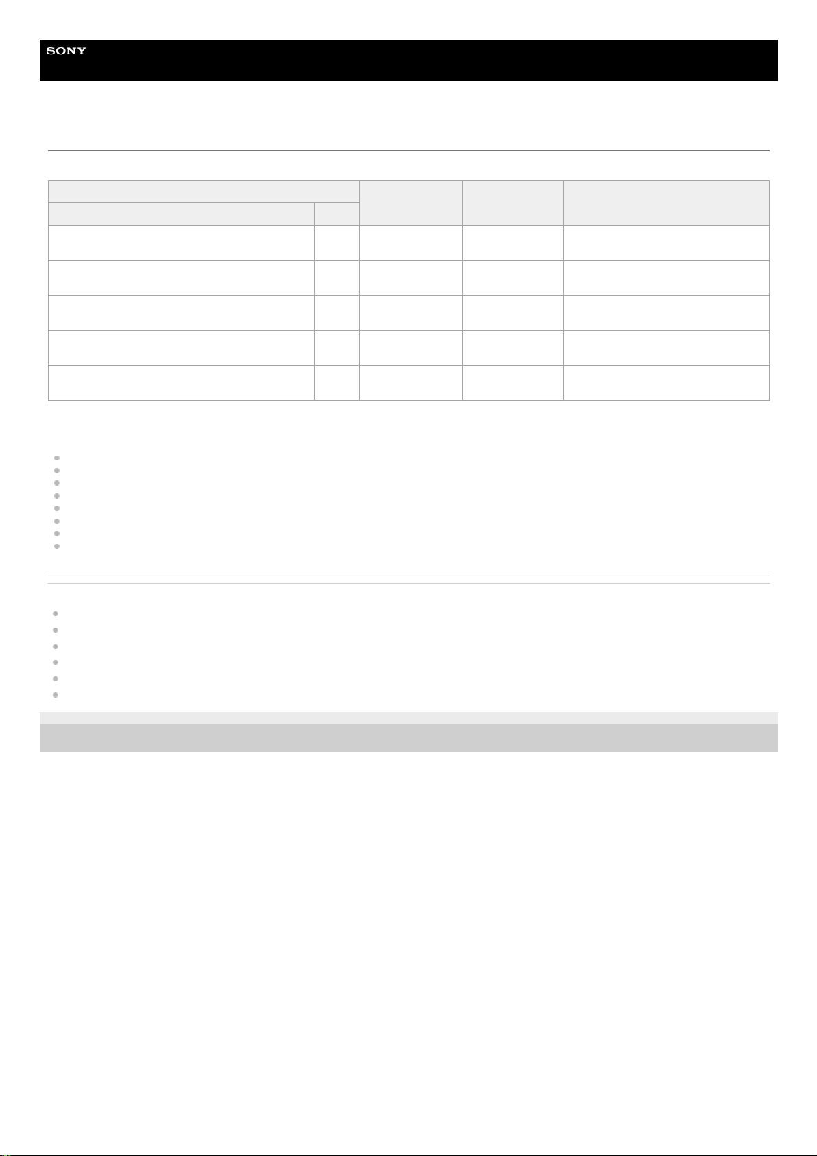
Speaker patterns and terminals to be connected
When you connect speakers to the receiver, refer to the following table.
You can use the following table to confirm the speaker patterns supported by the receiver as well as the speaker terminals to which the speakers of each speaker
pattern are to be connected.
To set the speaker pattern, select [Setup] - [Speaker Setup] - [Speaker Pattern] from the home menu.
The abbreviations and symbol used in the list are as follows.
FH: Front high speakers
TF: Top front speakers
TM: Top middle speakers
TR: Top rear speakers
RH: Rear high speakers
FD: Front Dolby Atmos enabled speakers
SRD: Surround Dolby Atmos enabled speakers
SBD: Surround back Dolby Atmos enabled speakers
△: There are no speaker terminals that can be assigned and output is enabled from the PRE OUT jacks only.
SB: SPEAKERS SURROUND BACK (FRONT B/BI-AMP/ZONE 2) terminals
H1: SPEAKERS HEIGHT 1 (ZONE 2) terminals
What the numbers in the speaker pattern indicate:
Number of speakers located at listener’s level
Number of subwoofers
Number of height or overhead (top) speakers
Speaker
pattern
SPEAKERS terminals/PRE OUT jacks
Zone 2
connection
(*1)
Front B
speaker
connection
(*1)
Bi-
amplifier
connection
(*1)
FRONT
A
CENTER SURROUND
SURROUND
BACK
(FRONT B/BIAMP/ZONE 2)
(single)
SURROUND
BACK
(FRONT B/BIAMP/ZONE 2)
(L/R)
HEIGHT
1
(ZONE
2)
HEIGHT
2
SUBWOOFER
2.0 ○ - - - - - - - SB or H1 SB SB
2.0.2
(TM)
○ - - - - ○ (TM) - - SB SB SB
2.0.2
(FD)
○ - - - - ○ (FD) - - SB SB SB
2.1 ○ - - - - - - ○ SB or H1 SB SB
2.1.2
(TM)
○ - - - - ○ (TM) - ○ SB SB SB
2.1.2
(FD)
○ - - - - ○ (FD) - ○ SB SB SB
3.0 ○ ○ - - - - - - SB or H1 SB SB
3.0.2
(TM)
○ ○ - - - ○ (TM) - - SB SB SB
3.0.2
(FD)
○ ○ - - - ○ (FD) - - SB SB SB
3.1 ○ ○ - - - - - ○ SB or H1 SB SB
3.1.2
(TM)
○ ○ - - - ○ (TM) - ○ SB SB SB
3.1.2
(FD)
○ ○ - - - ○ (FD) - ○ SB SB SB
If you are connecting speakers to SPEAKERS SURROUND BACK (FRONT B/BI-AMP/ZONE 2) terminals, select one of the following three connection methods: “Zone 2 connection,” “front B speaker
connection,” or “bi-amplifier connection.”
*1
If you are connecting speakers to SPEAKERS SURROUND BACK (FRONT B/BI-AMP/ZONE 2) terminals for Zone 2, front B speaker or bi-amplifier connection, the SPEAKERS HEIGHT 2 terminals
cannot be used for height speakers. In this case, use the PRE OUT HEIGHT 2 jacks instead.
*2
Speaker
pattern
SPEAKERS terminals/PRE OUT jacks Zone 2
connection
(*1)
Front B
speaker
Bi-
amplifier
35
Page 36

connection
(*1)
connection
(*1)
FRONT
A
CENTER SURROUND
SURROUND
BACK
(FRONT
B/BI-
AMP/ZONE
2) (single)
SURROUND
BACK
(FRONT
B/BI-
AMP/ZONE
2) (L/R)
HEIGHT
1
(ZONE
2)
HEIGHT
2
SUBWOOFER
Speaker
pattern
SPEAKERS terminals/PRE OUT jacks Zone 2
connection
(*1)
Front B
speaker
connection
(*1)
Bi-
amplifier
connection
(*1)
FRONT
A
CENTER SURROUND
SURROUND
BACK
(FRONT
B/BI-
AMP/ZONE
2) (single)
SURROUND
BACK
(FRONT
B/BI-
AMP/ZONE
2) (L/R)
HEIGHT
1
(ZONE
2)
HEIGHT
2
SUBWOOFER
4.0 ○ - ○ - - - - - SB or H1 SB SB
4.0.2 (FH) ○ - ○ - - ○ (FH) - - SB SB SB
4.0.2 (TM) ○ - ○ - - ○ (TM) - - SB SB SB
4.0.2 (FD) ○ - ○ - - ○ (FD) - - SB SB SB
4.0.2
(SRD)
○ - ○ - - ○ (SRD) - - SB SB SB
4.0.4
(FH+TM)
○ - ○ - - ○ (FH)
○ (TM)
(*2)
- SB SB SB
4.0.4
(FH+TR)
○ - ○ - - ○ (FH)
○ (TR)
(*2)
- SB SB SB
4.0.4
(FH+RH)
○ - ○ - - ○ (FH)
○ (RH)
(*2)
- SB SB SB
4.0.4
(TF+TM)
○ - ○ - - ○ (TF)
○ (TM)
(*2)
- SB SB SB
4.0.4
(TF+TR)
○ - ○ - - ○ (TF)
○ (TR)
(*2)
- SB SB SB
4.0.4
(TF+RH)
○ - ○ - - ○ (TF)
○ (RH)
(*2)
- SB SB SB
4.0.4
(TM+TR)
○ - ○ - - ○ (TM)
○ (TR)
(*2)
- SB SB SB
4.0.4
(TM+RH)
○ - ○ - - ○ (TM)
○ (RH)
(*2)
- SB SB SB
4.0.4
(FD+SRD)
○ - ○ - - ○ (FD)
○ (SRD)
(*2)
- SB SB SB
If you are connecting speakers to SPEAKERS SURROUND BACK (FRONT B/BI-AMP/ZONE 2) terminals, select one of the following three connection methods: “Zone 2 connection,” “front B speaker
connection,” or “bi-amplifier connection.”
*1
If you are connecting speakers to SPEAKERS SURROUND BACK (FRONT B/BI-AMP/ZONE 2) terminals for Zone 2, front B speaker or bi-amplifier connection, the SPEAKERS HEIGHT 2 terminals
cannot be used for height speakers. In this case, use the PRE OUT HEIGHT 2 jacks instead.
*2
Speaker
pattern
SPEAKERS terminals/PRE OUT jacks
Zone 2
connection
(*1)
Front B
speaker
connection
(*1)
Bi-
amplifier
connection
(*1)
FRONT
A
CENTER SURROUND
SURROUND
BACK
(FRONT
B/BI-
AMP/ZONE
2) (single)
SURROUND
BACK
(FRONT
B/BI-
AMP/ZONE
2) (L/R)
HEIGHT
1
(ZONE
2)
HEIGHT
2
SUBWOOFER
4.1 ○ - ○ - - - - ○ SB or H1 SB SB
4.1.2 (FH) ○ - ○ - - ○ (FH) - ○ SB SB SB
4.1.2 (TM) ○ - ○ - - ○ (TM) - ○ SB SB SB
4.1.2 (FD) ○ - ○ - - ○ (FD) - ○ SB SB SB
4.1.2
(SRD)
○ - ○ - - ○ (SRD) - ○ SB SB SB
4.1.4
(FH+TM)
○ - ○ - - ○ (FH)
○ (TM)
(*2)
○ SB SB SB
4.1.4
(FH+TR)
○ - ○ - - ○ (FH)
○ (TR)
(*2)
○ SB SB SB
4.1.4
(FH+RH)
○ - ○ - - ○ (FH)
○ (RH)
(*2)
○ SB SB SB
4.1.4
(TF+TM)
○ - ○ - - ○ (TF)
○ (TM)
(*2)
○ SB SB SB
4.1.4
(TF+TR)
○ - ○ - - ○ (TF)
○ (TR)
(*2)
○ SB SB SB
36
Page 37

Speaker
pattern
SPEAKERS terminals/PRE OUT jacks
Zone 2
connection
(*1)
Front B
speaker
connection
(*1)
Bi-
amplifier
connection
(*1)
FRONT
A
CENTER SURROUND
SURROUND
BACK
(FRONT
B/BI-
AMP/ZONE
2) (single)
SURROUND
BACK
(FRONT
B/BI-
AMP/ZONE
2) (L/R)
HEIGHT
1
(ZONE
2)
HEIGHT
2
SUBWOOFER
4.1.4
(TF+RH)
○ - ○ - - ○ (TF)
○ (RH)
(*2)
○ SB SB SB
4.1.4
(TM+TR)
○ - ○ - - ○ (TM)
○ (TR)
(*2)
○ SB SB SB
4.1.4
(TM+RH)
○ - ○ - - ○ (TM)
○ (RH)
(*2)
○ SB SB SB
4.1.4
(FD+SRD)
○ - ○ - - ○ (FD)
○ (SRD)
(*2)
○ SB SB SB
If you are connecting speakers to SPEAKERS SURROUND BACK (FRONT B/BI-AMP/ZONE 2) terminals, select one of the following three connection methods: “Zone 2 connection,” “front B speaker
connection,” or “bi-amplifier connection.”
*1
If you are connecting speakers to SPEAKERS SURROUND BACK (FRONT B/BI-AMP/ZONE 2) terminals for Zone 2, front B speaker or bi-amplifier connection, the SPEAKERS HEIGHT 2 terminals
cannot be used for height speakers. In this case, use the PRE OUT HEIGHT 2 jacks instead.
*2
Speaker
pattern
SPEAKERS terminals/PRE OUT jacks
Zone 2
connection
(*1)
Front B
speaker
connection
(*1)
Bi-
amplifier
connection
(*1)
FRONT
A
CENTER SURROUND
SURROUND
BACK
(FRONT
B/BI-
AMP/ZONE
2) (single)
SURROUND
BACK
(FRONT
B/BI-
AMP/ZONE
2) (L/R)
HEIGHT
1
(ZONE
2)
HEIGHT
2
SUBWOOFER
5.0 ○ ○ ○ - - - - - SB or H1 SB SB
5.0.2 (FH) ○ ○ ○ - - ○ (FH) - - SB SB SB
5.0.2 (TM) ○ ○ ○ - - ○ (TM) - - SB SB SB
5.0.2 (FD) ○ ○ ○ - - ○ (FD) - - SB SB SB
5.0.2
(SRD)
○ ○ ○ - - ○ (SRD) - - SB SB SB
5.0.4
(FH+TM)
○ ○ ○ - - ○ (FH)
○ (TM)
(*2)
- SB SB SB
5.0.4
(FH+TR)
○ ○ ○ - - ○ (FH)
○ (TR)
(*2)
- SB SB SB
5.0.4
(FH+RH)
○ ○ ○ - - ○ (FH)
○ (RH)
(*2)
- SB SB SB
5.0.4
(TF+TM)
○ ○ ○ - - ○ (TF)
○ (TM)
(*2)
- SB SB SB
5.0.4
(TF+TR)
○ ○ ○ - - ○ (TF)
○ (TR)
(*2)
- SB SB SB
5.0.4
(TF+RH)
○ ○ ○ - - ○ (TF)
○ (RH)
(*2)
- SB SB SB
5.0.4
(TM+TR)
○ ○ ○ - - ○ (TM)
○ (TR)
(*2)
- SB SB SB
5.0.4
(TM+RH)
○ ○ ○ - - ○ (TM)
○ (RH)
(*2)
- SB SB SB
5.0.4
(FD+SRD)
○ ○ ○ - - ○ (FD)
○ (SRD)
(*2)
- SB SB SB
If you are connecting speakers to SPEAKERS SURROUND BACK (FRONT B/BI-AMP/ZONE 2) terminals, select one of the following three connection methods: “Zone 2 connection,” “front B speaker
connection,” or “bi-amplifier connection.”
*1
If you are connecting speakers to SPEAKERS SURROUND BACK (FRONT B/BI-AMP/ZONE 2) terminals for Zone 2, front B speaker or bi-amplifier connection, the SPEAKERS HEIGHT 2 terminals
cannot be used for height speakers. In this case, use the PRE OUT HEIGHT 2 jacks instead.
*2
Speaker
pattern
SPEAKERS terminals/PRE OUT jacks
Zone 2
connection
(*1)
Front B
speaker
connection
(*1)
Bi-
amplifier
connection
(*1)
FRONT
A
CENTER SURROUND
SURROUND
BACK
(FRONT
B/BI-
AMP/ZONE
2) (single)
SURROUND
BACK
(FRONT
B/BI-
AMP/ZONE
2) (L/R)
HEIGHT
1
(ZONE
2)
HEIGHT
2
SUBWOOFER
5.1 ○ ○ ○ - - - - ○ SB or H1 SB SB
37
Page 38

Speaker
pattern
SPEAKERS terminals/PRE OUT jacks
Zone 2
connection
(*1)
Front B
speaker
connection
(*1)
Bi-
amplifier
connection
(*1)
FRONT
A
CENTER SURROUND
SURROUND
BACK
(FRONT
B/BI-
AMP/ZONE
2) (single)
SURROUND
BACK
(FRONT
B/BI-
AMP/ZONE
2) (L/R)
HEIGHT
1
(ZONE
2)
HEIGHT
2
SUBWOOFER
5.1.2 (FH) ○ ○ ○ - - ○ (FH) - ○ SB SB SB
5.1.2 (TM) ○ ○ ○ - - ○ (TM) - ○ SB SB SB
5.1.2 (FD) ○ ○ ○ - - ○ (FD) - ○ SB SB SB
5.1.2
(SRD)
○ ○ ○ - - ○ (SRD) - ○ SB SB SB
5.1.4
(FH+TM)
○ ○ ○ - - ○ (FH)
○ (TM)
(*2)
○ SB SB SB
5.1.4
(FH+TR)
○ ○ ○ - - ○ (FH)
○ (TR)
(*2)
○ SB SB SB
5.1.4
(FH+RH)
○ ○ ○ - - ○ (FH)
○ (RH)
(*2)
○ SB SB SB
5.1.4
(TF+TM)
○ ○ ○ - - ○ (TF)
○ (TM)
(*2)
○ SB SB SB
5.1.4
(TF+TR)
○ ○ ○ - - ○ (TF)
○ (TR)
(*2)
○ SB SB SB
5.1.4
(TF+RH)
○ ○ ○ - - ○ (TF)
○ (RH)
(*2)
○ SB SB SB
5.1.4
(TM+TR)
○ ○ ○ - - ○ (TM)
○ (TR)
(*2)
○ SB SB SB
5.1.4
(TM+RH)
○ ○ ○ - - ○ (TM)
○ (RH)
(*2)
○ SB SB SB
5.1.4
(FD+SRD)
○ ○ ○ - - ○ (FD)
○ (SRD)
(*2)
○ SB SB SB
If you are connecting speakers to SPEAKERS SURROUND BACK (FRONT B/BI-AMP/ZONE 2) terminals, select one of the following three connection methods: “Zone 2 connection,” “front B speaker
connection,” or “bi-amplifier connection.”
*1
If you are connecting speakers to SPEAKERS SURROUND BACK (FRONT B/BI-AMP/ZONE 2) terminals for Zone 2, front B speaker or bi-amplifier connection, the SPEAKERS HEIGHT 2 terminals
cannot be used for height speakers. In this case, use the PRE OUT HEIGHT 2 jacks instead.
*2
Speaker
pattern
SPEAKERS terminals/PRE OUT jacks
Zone 2
connection
(*1)
Front B
speaker
connection
(*1)
Bi-
amplifier
connection
(*1)
FRONT
A
CENTER SURROUND
SURROUND
BACK
(FRONT
B/BI-
AMP/ZONE
2) (single)
SURROUND
BACK
(FRONT
B/BI-
AMP/ZONE
2) (L/R)
HEIGHT
1
(ZONE
2)
HEIGHT
2
SUBWOOFER
5.0 (SB) ○ - ○ ○ - - - - H1
Not
available
Not
available
5.0.2 (SB+FH) ○ - ○ ○ - ○ (FH) - -
Only PRE
OUT
Not
available
Not
available
5.0.2 (SB+TM) ○ - ○ ○ - ○ (TM) - -
Only PRE
OUT
Not
available
Not
available
5.0.2 (SB+FD) ○ - ○ ○ - ○ (FD) - -
Only PRE
OUT
Not
available
Not
available
5.0.2
(SB+SRD)
○ - ○ ○ - ○ (SRD) - -
Only PRE
OUT
Not
available
Not
available
5.0.4
(SB+FH+TM)
○ - ○ ○ - ○ (FH) △ (TM) -
Only PRE
OUT
Not
available
Not
available
5.0.4
(SB+FH+TR)
○ - ○ ○ - ○ (FH) △ (TR) -
Only PRE
OUT
Not
available
Not
available
5.0.4
(SB+FH+RH)
○ - ○ ○ - ○ (FH) △ (RH) -
Only PRE
OUT
Not
available
Not
available
5.0.4
(SB+TF+TM)
○ - ○ ○ - ○ (TF) △ (TM) -
Only PRE
OUT
Not
available
Not
available
5.0.4
(SB+TF+TR)
○ - ○ ○ - ○ (TF) △ (TR) -
Only PRE
OUT
Not
available
Not
available
38
Page 39

Speaker
pattern
SPEAKERS terminals/PRE OUT jacks
Zone 2
connection
(*1)
Front B
speaker
connection
(*1)
Bi-
amplifier
connection
(*1)
FRONT
A
CENTER SURROUND
SURROUND
BACK
(FRONT
B/BI-
AMP/ZONE
2) (single)
SURROUND
BACK
(FRONT
B/BI-
AMP/ZONE
2) (L/R)
HEIGHT
1
(ZONE
2)
HEIGHT
2
SUBWOOFER
5.0.4
(SB+TF+RH)
○ - ○ ○ - ○ (TF) △ (RH) -
Only PRE
OUT
Not
available
Not
available
5.0.4
(SB+TM+TR)
○ - ○ ○ - ○ (TM) △ (TR) -
Only PRE
OUT
Not
available
Not
available
5.0.4
(SB+TM+RH)
○ - ○ ○ - ○ (TM) △ (RH) -
Only PRE
OUT
Not
available
Not
available
5.0.4
(SB+FD+SRD)
○ - ○ ○ - ○ (FD)
△
(SRD)
-
Only PRE
OUT
Not
available
Not
available
If you are connecting speakers to SPEAKERS SURROUND BACK (FRONT B/BI-AMP/ZONE 2) terminals, select one of the following three connection methods: “Zone 2 connection,” “front B speaker
connection,” or “bi-amplifier connection.”
*1
If you are connecting speakers to SPEAKERS SURROUND BACK (FRONT B/BI-AMP/ZONE 2) terminals for Zone 2, front B speaker or bi-amplifier connection, the SPEAKERS HEIGHT 2 terminals
cannot be used for height speakers. In this case, use the PRE OUT HEIGHT 2 jacks instead.
*2
Speaker
pattern
SPEAKERS terminals/PRE OUT jacks
Zone 2
connection
(*1)
Front B
speaker
connection
(*1)
Bi-
amplifier
connection
(*1)
FRONT
A
CENTER SURROUND
SURROUND
BACK
(FRONT
B/BI-
AMP/ZONE
2) (single)
SURROUND
BACK
(FRONT
B/BI-
AMP/ZONE
2) (L/R)
HEIGHT
1
(ZONE
2)
HEIGHT
2
SUBWOOFER
5.1 (SB) ○ - ○ ○ - - - ○ H1
Not
available
Not
available
5.1.2 (SB+FH) ○ - ○ ○ - ○ (FH) - ○
Only PRE
OUT
Not
available
Not
available
5.1.2 (SB+TM) ○ - ○ ○ - ○ (TM) - ○
Only PRE
OUT
Not
available
Not
available
5.1.2 (SB+FD) ○ - ○ ○ - ○ (FD) - ○
Only PRE
OUT
Not
available
Not
available
5.1.2
(SB+SRD)
○ - ○ ○ - ○ (SRD) - ○
Only PRE
OUT
Not
available
Not
available
5.1.4
(SB+FH+TM)
○ - ○ ○ - ○ (FH) △ (TM) ○
Only PRE
OUT
Not
available
Not
available
5.1.4
(SB+FH+TR)
○ - ○ ○ - ○ (FH) △ (TR) ○
Only PRE
OUT
Not
available
Not
available
5.1.4
(SB+FH+RH)
○ - ○ ○ - ○ (FH) △ (RH) ○
Only PRE
OUT
Not
available
Not
available
5.1.4
(SB+TF+TM)
○ - ○ ○ - ○ (TF) △ (TM) ○
Only PRE
OUT
Not
available
Not
available
5.1.4
(SB+TF+TR)
○ - ○ ○ - ○ (TF) △ (TR) ○
Only PRE
OUT
Not
available
Not
available
5.1.4
(SB+TF+RH)
○ - ○ ○ - ○ (TF) △ (RH) ○
Only PRE
OUT
Not
available
Not
available
5.1.4
(SB+TM+TR)
○ - ○ ○ - ○ (TM) △ (TR) ○
Only PRE
OUT
Not
available
Not
available
5.1.4
(SB+TM+RH)
○ - ○ ○ - ○ (TM) △ (RH) ○
Only PRE
OUT
Not
available
Not
available
5.1.4
(SB+FD+SRD)
○ - ○ ○ - ○ (FD)
△
(SRD)
○
Only PRE
OUT
Not
available
Not
available
If you are connecting speakers to SPEAKERS SURROUND BACK (FRONT B/BI-AMP/ZONE 2) terminals, select one of the following three connection methods: “Zone 2 connection,” “front B speaker
connection,” or “bi-amplifier connection.”
*1
If you are connecting speakers to SPEAKERS SURROUND BACK (FRONT B/BI-AMP/ZONE 2) terminals for Zone 2, front B speaker or bi-amplifier connection, the SPEAKERS HEIGHT 2 terminals
cannot be used for height speakers. In this case, use the PRE OUT HEIGHT 2 jacks instead.
*2
Speaker
pattern
SPEAKERS terminals/PRE OUT jacks Zone 2
connection
(*1)
Front B
speaker
connection
(*1)
Bi-
amplifier
connection
(*1)
39
Page 40

FRONT
A
CENTER SURROUND
SURROUND
BACK
(FRONT
B/BI-
AMP/ZONE
2) (single)
SURROUND
BACK
(FRONT
B/BI-
AMP/ZONE
2) (L/R)
HEIGHT
1
(ZONE
2)
HEIGHT
2
SUBWOOFER
Speaker
pattern
SPEAKERS terminals/PRE OUT jacks Zone 2
connection
(*1)
Front B
speaker
connection
(*1)
Bi-
amplifier
connection
(*1)
FRONT
A
CENTER SURROUND
SURROUND
BACK
(FRONT
B/BI-
AMP/ZONE
2) (single)
SURROUND
BACK
(FRONT
B/BI-
AMP/ZONE
2) (L/R)
HEIGHT
1
(ZONE
2)
HEIGHT
2
SUBWOOFER
6.0 (SB) ○ ○ ○ ○ - - - - H1
Not
available
Not
available
6.0.2 (SB+FH) ○ ○ ○ ○ - ○ (FH) - -
Only PRE
OUT
Not
available
Not
available
6.0.2 (SB+TM) ○ ○ ○ ○ - ○ (TM) - -
Only PRE
OUT
Not
available
Not
available
6.0.2 (SB+FD) ○ ○ ○ ○ - ○ (FD) - -
Only PRE
OUT
Not
available
Not
available
6.0.2
(SB+SRD)
○ ○ ○ ○ - ○ (SRD) - -
Only PRE
OUT
Not
available
Not
available
6.0.4
(SB+FH+TM)
○ ○ ○ ○ - ○ (FH) △ (TM) -
Only PRE
OUT
Not
available
Not
available
6.0.4
(SB+FH+TR)
○ ○ ○ ○ - ○ (FH) △ (TR) -
Only PRE
OUT
Not
available
Not
available
6.0.4
(SB+FH+RH)
○ ○ ○ ○ - ○ (FH) △ (RH) -
Only PRE
OUT
Not
available
Not
available
6.0.4
(SB+TF+TM)
○ ○ ○ ○ - ○ (TF) △ (TM) -
Only PRE
OUT
Not
available
Not
available
6.0.4
(SB+TF+TR)
○ ○ ○ ○ - ○ (TF) △ (TR) -
Only PRE
OUT
Not
available
Not
available
6.0.4
(SB+TF+RH)
○ ○ ○ ○ - ○ (TF) △ (RH) -
Only PRE
OUT
Not
available
Not
available
6.0.4
(SB+TM+TR)
○ ○ ○ ○ - ○ (TM) △ (TR) -
Only PRE
OUT
Not
available
Not
available
6.0.4
(SB+TM+RH)
○ ○ ○ ○ - ○ (TM) △ (RH) -
Only PRE
OUT
Not
available
Not
available
6.0.4
(SB+FD+SRD)
○ ○ ○ ○ - ○ (FD)
△
(SRD)
-
Only PRE
OUT
Not
available
Not
available
If you are connecting speakers to SPEAKERS SURROUND BACK (FRONT B/BI-AMP/ZONE 2) terminals, select one of the following three connection methods: “Zone 2 connection,” “front B speaker
connection,” or “bi-amplifier connection.”
*1
If you are connecting speakers to SPEAKERS SURROUND BACK (FRONT B/BI-AMP/ZONE 2) terminals for Zone 2, front B speaker or bi-amplifier connection, the SPEAKERS HEIGHT 2 terminals
cannot be used for height speakers. In this case, use the PRE OUT HEIGHT 2 jacks instead.
*2
Speaker
pattern
SPEAKERS terminals/PRE OUT jacks
Zone 2
connection
(*1)
Front B
speaker
connection
(*1)
Bi-
amplifier
connection
(*1)
FRONT
A
CENTER SURROUND
SURROUND
BACK
(FRONT
B/BI-
AMP/ZONE
2) (single)
SURROUND
BACK
(FRONT
B/BI-
AMP/ZONE
2) (L/R)
HEIGHT
1
(ZONE
2)
HEIGHT
2
SUBWOOFER
6.1 (SB) ○ ○ ○ ○ - - - ○ H1
Not
available
Not
available
6.1.2 (SB+FH) ○ ○ ○ ○ - ○ (FH) - ○
Only PRE
OUT
Not
available
Not
available
6.1.2 (SB+TM) ○ ○ ○ ○ - ○ (TM) - ○
Only PRE
OUT
Not
available
Not
available
6.1.2 (SB+FD) ○ ○ ○ ○ - ○ (FD) - ○
Only PRE
OUT
Not
available
Not
available
6.1.2
(SB+SRD)
○ ○ ○ ○ - ○ (SRD) - ○
Only PRE
OUT
Not
available
Not
available
6.1.4
(SB+FH+TM)
○ ○ ○ ○ - ○ (FH) △ (TM) ○
Only PRE
OUT
Not
available
Not
available
40
Page 41

Speaker
pattern
SPEAKERS terminals/PRE OUT jacks
Zone 2
connection
(*1)
Front B
speaker
connection
(*1)
Bi-
amplifier
connection
(*1)
FRONT
A
CENTER SURROUND
SURROUND
BACK
(FRONT
B/BI-
AMP/ZONE
2) (single)
SURROUND
BACK
(FRONT
B/BI-
AMP/ZONE
2) (L/R)
HEIGHT
1
(ZONE
2)
HEIGHT
2
SUBWOOFER
6.1.4
(SB+FH+TR)
○ ○ ○ ○ - ○ (FH) △ (TR) ○
Only PRE
OUT
Not
available
Not
available
6.1.4
(SB+FH+RH)
○ ○ ○ ○ - ○ (FH) △ (RH) ○
Only PRE
OUT
Not
available
Not
available
6.1.4
(SB+TF+TM)
○ ○ ○ ○ - ○ (TF) △ (TM) ○
Only PRE
OUT
Not
available
Not
available
6.1.4
(SB+TF+TR)
○ ○ ○ ○ - ○ (TF) △ (TR) ○
Only PRE
OUT
Not
available
Not
available
6.1.4
(SB+TF+RH)
○ ○ ○ ○ - ○ (TF) △ (RH) ○
Only PRE
OUT
Not
available
Not
available
6.1.4
(SB+TM+TR)
○ ○ ○ ○ - ○ (TM) △ (TR) ○
Only PRE
OUT
Not
available
Not
available
6.1.4
(SB+TM+RH)
○ ○ ○ ○ - ○ (TM) △ (RH) ○
Only PRE
OUT
Not
available
Not
available
6.1.4
(SB+FD+SRD)
○ ○ ○ ○ - ○ (FD)
△
(SRD)
○
Only PRE
OUT
Not
available
Not
available
If you are connecting speakers to SPEAKERS SURROUND BACK (FRONT B/BI-AMP/ZONE 2) terminals, select one of the following three connection methods: “Zone 2 connection,” “front B speaker
connection,” or “bi-amplifier connection.”
*1
If you are connecting speakers to SPEAKERS SURROUND BACK (FRONT B/BI-AMP/ZONE 2) terminals for Zone 2, front B speaker or bi-amplifier connection, the SPEAKERS HEIGHT 2 terminals
cannot be used for height speakers. In this case, use the PRE OUT HEIGHT 2 jacks instead.
*2
Speaker
pattern
SPEAKERS terminals/PRE OUT jacks
Zone 2
connection
(*1)
Front B
speaker
connection
(*1)
Bi-
amplifier
connection
(*1)
FRONT
A
CENTER SURROUND
SURROUND
BACK
(FRONT
B/BI-
AMP/ZONE
2) (single)
SURROUND
BACK
(FRONT
B/BI-
AMP/ZONE
2) (L/R)
HEIGHT
1
(ZONE
2)
HEIGHT
2
SUBWOOFER
6.0 ○ - ○ - ○ - - - H1
Not
available
Not
available
6.0.2 (FH) ○ - ○ - ○ ○ (FH) - -
Only PRE
OUT
Not
available
Not
available
6.0.2 (TM) ○ - ○ - ○ ○ (TM) - -
Only PRE
OUT
Not
available
Not
available
6.0.2 (FD) ○ - ○ - ○ ○ (FD) - -
Only PRE
OUT
Not
available
Not
available
6.0.2
(SRD)
○ - ○ - ○ ○ (SRD) - -
Only PRE
OUT
Not
available
Not
available
6.0.2
(SBD)
○ - ○ - ○ ○ (SBD) - -
Only PRE
OUT
Not
available
Not
available
6.0.4
(FH+TM)
○ - ○ - ○ ○ (FH) △ (TM) -
Only PRE
OUT
Not
available
Not
available
6.0.4
(FH+TR)
○ - ○ - ○ ○ (FH) △ (TR) -
Only PRE
OUT
Not
available
Not
available
6.0.4
(FH+RH)
○ - ○ - ○ ○ (FH) △ (RH) -
Only PRE
OUT
Not
available
Not
available
6.0.4
(TF+TM)
○ - ○ - ○ ○ (TF) △ (TM) -
Only PRE
OUT
Not
available
Not
available
6.0.4
(TF+TR)
○ - ○ - ○ ○ (TF) △ (TR) -
Only PRE
OUT
Not
available
Not
available
6.0.4
(TF+RH)
○ - ○ - ○ ○ (TF) △ (RH) -
Only PRE
OUT
Not
available
Not
available
6.0.4
(TM+TR)
○ - ○ - ○ ○ (TM) △ (TR) -
Only PRE
OUT
Not
available
Not
available
6.0.4
(TM+RH)
○ - ○ - ○ ○ (TM) △ (RH) -
Only PRE
OUT
Not
available
Not
available
41
Page 42

Speaker
pattern
SPEAKERS terminals/PRE OUT jacks
Zone 2
connection
(*1)
Front B
speaker
connection
(*1)
Bi-
amplifier
connection
(*1)
FRONT
A
CENTER SURROUND
SURROUND
BACK
(FRONT
B/BI-
AMP/ZONE
2) (single)
SURROUND
BACK
(FRONT
B/BI-
AMP/ZONE
2) (L/R)
HEIGHT
1
(ZONE
2)
HEIGHT
2
SUBWOOFER
6.0.4
(FD+SBD)
○ - ○ - ○ ○ (FD)
△
(SBD)
-
Only PRE
OUT
Not
available
Not
available
If you are connecting speakers to SPEAKERS SURROUND BACK (FRONT B/BI-AMP/ZONE 2) terminals, select one of the following three connection methods: “Zone 2 connection,” “front B speaker
connection,” or “bi-amplifier connection.”
*1
If you are connecting speakers to SPEAKERS SURROUND BACK (FRONT B/BI-AMP/ZONE 2) terminals for Zone 2, front B speaker or bi-amplifier connection, the SPEAKERS HEIGHT 2 terminals
cannot be used for height speakers. In this case, use the PRE OUT HEIGHT 2 jacks instead.
*2
Speaker
pattern
SPEAKERS terminals/PRE OUT jacks
Zone 2
connection
(*1)
Front B
speaker
connection
(*1)
Bi-
amplifier
connection
(*1)
FRONT
A
CENTER SURROUND
SURROUND
BACK
(FRONT
B/BI-
AMP/ZONE
2) (single)
SURROUND
BACK
(FRONT
B/BI-
AMP/ZONE
2) (L/R)
HEIGHT
1
(ZONE
2)
HEIGHT
2
SUBWOOFER
6.1 ○ - ○ - ○ - - ○ H1
Not
available
Not
available
6.1.2 (FH) ○ - ○ - ○ ○ (FH) - ○
Only PRE
OUT
Not
available
Not
available
6.1.2 (TM) ○ - ○ - ○ ○ (TM) - ○
Only PRE
OUT
Not
available
Not
available
6.1.2 (FD) ○ - ○ - ○ ○ (FD) - ○
Only PRE
OUT
Not
available
Not
available
6.1.2
(SRD)
○ - ○ - ○ ○ (SRD) - ○
Only PRE
OUT
Not
available
Not
available
6.1.2
(SBD)
○ - ○ - ○ ○ (SBD) - ○
Only PRE
OUT
Not
available
Not
available
6.1.4
(FH+TM)
○ - ○ - ○ ○ (FH) △ (TM) ○
Only PRE
OUT
Not
available
Not
available
6.1.4
(FH+TR)
○ - ○ - ○ ○ (FH) △ (TR) ○
Only PRE
OUT
Not
available
Not
available
6.1.4
(FH+RH)
○ - ○ - ○ ○ (FH) △ (RH) ○
Only PRE
OUT
Not
available
Not
available
6.1.4
(TF+TM)
○ - ○ - ○ ○ (TF) △ (TM) ○
Only PRE
OUT
Not
available
Not
available
6.1.4
(TF+TR)
○ - ○ - ○ ○ (TF) △ (TR) ○
Only PRE
OUT
Not
available
Not
available
6.1.4
(TF+RH)
○ - ○ - ○ ○ (TF) △ (RH) ○
Only PRE
OUT
Not
available
Not
available
6.1.4
(TM+TR)
○ - ○ - ○ ○ (TM) △ (TR) ○
Only PRE
OUT
Not
available
Not
available
6.1.4
(TM+RH)
○ - ○ - ○ ○ (TM) △ (RH) ○
Only PRE
OUT
Not
available
Not
available
6.1.4
(FD+SBD)
○ - ○ - ○ ○ (FD)
△
(SBD)
○
Only PRE
OUT
Not
available
Not
available
If you are connecting speakers to SPEAKERS SURROUND BACK (FRONT B/BI-AMP/ZONE 2) terminals, select one of the following three connection methods: “Zone 2 connection,” “front B speaker
connection,” or “bi-amplifier connection.”
*1
If you are connecting speakers to SPEAKERS SURROUND BACK (FRONT B/BI-AMP/ZONE 2) terminals for Zone 2, front B speaker or bi-amplifier connection, the SPEAKERS HEIGHT 2 terminals
cannot be used for height speakers. In this case, use the PRE OUT HEIGHT 2 jacks instead.
*2
Speaker
pattern
SPEAKERS terminals/PRE OUT jacks
Zone 2
connection
(*1)
Front B
speaker
connection
(*1)
Bi-
amplifier
connection
(*1)
FRONT
A
CENTER SURROUND
SURROUND
BACK
(FRONT
B/BI-
AMP/ZONE
2) (single)
SURROUND
BACK
(FRONT
B/BI-
AMP/ZONE
2) (L/R)
HEIGHT
1
(ZONE
2)
HEIGHT
2
SUBWOOFER
7.0 ○ ○ ○ - ○ - - - H1
Not
available
Not
available
42
Page 43

Speaker
pattern
SPEAKERS terminals/PRE OUT jacks
Zone 2
connection
(*1)
Front B
speaker
connection
(*1)
Bi-
amplifier
connection
(*1)
FRONT
A
CENTER SURROUND
SURROUND
BACK
(FRONT
B/BI-
AMP/ZONE
2) (single)
SURROUND
BACK
(FRONT
B/BI-
AMP/ZONE
2) (L/R)
HEIGHT
1
(ZONE
2)
HEIGHT
2
SUBWOOFER
7.0.2 (FH) ○ ○ ○ - ○ ○ (FH) - -
Only PRE
OUT
Not
available
Not
available
7.0.2 (TM) ○ ○ ○ - ○ ○ (TM) - -
Only PRE
OUT
Not
available
Not
available
7.0.2 (FD) ○ ○ ○ - ○ ○ (FD) - -
Only PRE
OUT
Not
available
Not
available
7.0.2
(SRD)
○ ○ ○ - ○ ○ (SRD) - -
Only PRE
OUT
Not
available
Not
available
7.0.2
(SBD)
○ ○ ○ - ○ ○ (SBD) - -
Only PRE
OUT
Not
available
Not
available
7.0.4
(FH+TM)
○ ○ ○ - ○ ○ (FH) △ (TM) -
Only PRE
OUT
Not
available
Not
available
7.0.4
(FH+TR)
○ ○ ○ - ○ ○ (FH) △ (TR) -
Only PRE
OUT
Not
available
Not
available
7.0.4
(FH+RH)
○ ○ ○ - ○ ○ (FH) △ (RH) -
Only PRE
OUT
Not
available
Not
available
7.0.4
(TF+TM)
○ ○ ○ - ○ ○ (TF) △ (TM) -
Only PRE
OUT
Not
available
Not
available
7.0.4
(TF+TR)
○ ○ ○ - ○ ○ (TF) △ (TR) -
Only PRE
OUT
Not
available
Not
available
7.0.4
(TF+RH)
○ ○ ○ - ○ ○ (TF) △ (RH) -
Only PRE
OUT
Not
available
Not
available
7.0.4
(TM+TR)
○ ○ ○ - ○ ○ (TM) △ (TR) -
Only PRE
OUT
Not
available
Not
available
7.0.4
(TM+RH)
○ ○ ○ - ○ ○ (TM) △ (RH) -
Only PRE
OUT
Not
available
Not
available
7.0.4
(FD+SBD)
○ ○ ○ - ○ ○ (FD)
△
(SBD)
-
Only PRE
OUT
Not
available
Not
available
If you are connecting speakers to SPEAKERS SURROUND BACK (FRONT B/BI-AMP/ZONE 2) terminals, select one of the following three connection methods: “Zone 2 connection,” “front B speaker
connection,” or “bi-amplifier connection.”
*1
If you are connecting speakers to SPEAKERS SURROUND BACK (FRONT B/BI-AMP/ZONE 2) terminals for Zone 2, front B speaker or bi-amplifier connection, the SPEAKERS HEIGHT 2 terminals
cannot be used for height speakers. In this case, use the PRE OUT HEIGHT 2 jacks instead.
*2
Speaker
pattern
SPEAKERS terminals/PRE OUT jacks
Zone 2
connection
(*1)
Front B
speaker
connection
(*1)
Bi-
amplifier
connection
(*1)
FRONT
A
CENTER SURROUND
SURROUND
BACK
(FRONT
B/BI-
AMP/ZONE
2) (single)
SURROUND
BACK
(FRONT
B/BI-
AMP/ZONE
2) (L/R)
HEIGHT
1
(ZONE
2)
HEIGHT
2
SUBWOOFER
7.1 ○ ○ ○ - ○ - - ○ H1
Not
available
Not
available
7.1.2 (FH) ○ ○ ○ - ○ ○ (FH) - ○
Only PRE
OUT
Not
available
Not
available
7.1.2 (TM) ○ ○ ○ - ○ ○ (TM) - ○
Only PRE
OUT
Not
available
Not
available
7.1.2 (FD) ○ ○ ○ - ○ ○ (FD) - ○
Only PRE
OUT
Not
available
Not
available
7.1.2
(SRD)
○ ○ ○ - ○ ○ (SRD) - ○
Only PRE
OUT
Not
available
Not
available
7.1.2
(SBD)
○ ○ ○ - ○ ○ (SBD) - ○
Only PRE
OUT
Not
available
Not
available
7.1.4
(FH+TM)
○ ○ ○ - ○ ○ (FH) △ (TM) ○
Only PRE
OUT
Not
available
Not
available
7.1.4
(FH+TR)
○ ○ ○ - ○ ○ (FH) △ (TR) ○
Only PRE
OUT
Not
available
Not
available
43
Page 44

4-587-297-12(5) Copyright 2016 Sony Corporation
Speaker
pattern
SPEAKERS terminals/PRE OUT jacks
Zone 2
connection
(*1)
Front B
speaker
connection
(*1)
Bi-
amplifier
connection
(*1)
FRONT
A
CENTER SURROUND
SURROUND
BACK
(FRONT
B/BI-
AMP/ZONE
2) (single)
SURROUND
BACK
(FRONT
B/BI-
AMP/ZONE
2) (L/R)
HEIGHT
1
(ZONE
2)
HEIGHT
2
SUBWOOFER
7.1.4
(FH+RH)
○ ○ ○ - ○ ○ (FH) △ (RH) ○
Only PRE
OUT
Not
available
Not
available
7.1.4
(TF+TM)
○ ○ ○ - ○ ○ (TF) △ (TM) ○
Only PRE
OUT
Not
available
Not
available
7.1.4
(TF+TR)
○ ○ ○ - ○ ○ (TF) △ (TR) ○
Only PRE
OUT
Not
available
Not
available
7.1.4
(TF+RH)
○ ○ ○ - ○ ○ (TF) △ (RH) ○
Only PRE
OUT
Not
available
Not
available
7.1.4
(TM+TR)
○ ○ ○ - ○ ○ (TM) △ (TR) ○
Only PRE
OUT
Not
available
Not
available
7.1.4
(TM+RH)
○ ○ ○ - ○ ○ (TM) △ (RH) ○
Only PRE
OUT
Not
available
Not
available
7.1.4
(FD+SBD)
○ ○ ○ - ○ ○ (FD)
△
(SBD)
○
Only PRE
OUT
Not
available
Not
available
If you are connecting speakers to SPEAKERS SURROUND BACK (FRONT B/BI-AMP/ZONE 2) terminals, select one of the following three connection methods: “Zone 2 connection,” “front B speaker
connection,” or “bi-amplifier connection.”
*1
If you are connecting speakers to SPEAKERS SURROUND BACK (FRONT B/BI-AMP/ZONE 2) terminals for Zone 2, front B speaker or bi-amplifier connection, the SPEAKERS HEIGHT 2 terminals
cannot be used for height speakers. In this case, use the PRE OUT HEIGHT 2 jacks instead.
*2
44
Page 45

Help Guide
MULTI CHANNEL AV RECEIVER
STR-ZA5000ES
Connecting a TV
Connect a TV to the HDMI OUT or MONITOR OUT jack. You can operate this receiver using the menu on the TV screen when you connect the TV to the HDMI OUT A
jack.
Be sure to disconnect the AC power cord (mains lead) before connecting cables.
Connecting a TV incompatible with the Audio Return Channel (ARC) function via an HDMI connection
Solid lines show recommended connections and the dashed lines show alternative connections for audio signals. It is not necessary to connect all the cables. HDMI
connection for audio/video signals is required.
Optical digital cable (not supplied)
Audio cable (not supplied)
HDMI cable (not supplied)
Note
Sony recommends that you use an HDMI-authorized cable or HDMI cable made by Sony. Be sure to use a High Speed HDMI Cable with Ethernet. Premium High Speed HDMI Cable
with Ethernet that supports 18 Gbps is required for 4K/60p 4:4:4, 4:2:2, and 4K/60p 4:2:0 10 bit, etc.
Connecting a TV compatible with the Audio Return Channel (ARC) function via an HDMI connection
With just one HDMI cable connection, you can listen to the TV audio from the speakers connected to the receiver while the receiver sends audio and video to the TV.
HDMI cable (not supplied)
Note
Sony recommends that you use an HDMI-authorized cable or HDMI cable made by Sony. Be sure to use a High Speed HDMI Cable with Ethernet. Premium High Speed HDMI Cable
with Ethernet that supports 18 Gbps is required for 4K/60p 4:4:4, 4:2:2, and 4K/60p 4:2:0 10 bit, etc.
45
Page 46
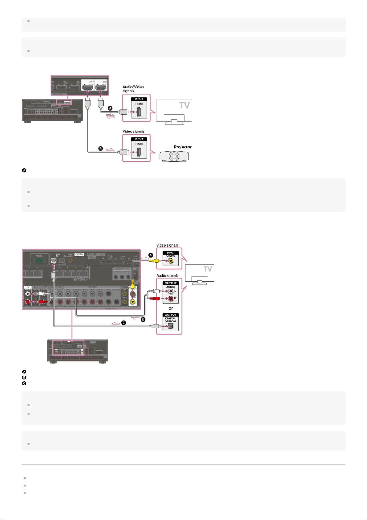
For this connection, you need to turn the Audio Return Channel function on. Press HOME to display the home menu, select [Setup] - [HDMI Setup], and set [Audio Return Channel] to
[On].
Hint
If the HDMI jack of the TV (labeled “ARC”) is already connected to another device, disconnect the device and connect the receiver.
Connecting a TV and a projector
HDMI cable (not supplied)
Note
Sony recommends that you use an HDMI-authorized cable or HDMI cable made by Sony. Be sure to use a High Speed HDMI Cable with Ethernet. Premium High Speed HDMI Cable
with Ethernet that supports 18 Gbps is required for 4K/60p 4:4:4, 4:2:2, and 4K/60p 4:2:0 10 bit, etc.
To use this connection in only one room, select [Setup] - [HDMI Setup], and set [HDMI Out B Mode] to [Main].
Connecting a TV without HDMI jacks
Solid lines show recommended connections and the dashed lines show alternative connections for both video and audio signals. It is not necessary to connect all the
cables.
Video cable (not supplied)
Audio cable (not supplied)
Optical digital cable (not supplied)
Note
The MONITOR VIDEO OUT jack can output video signal input from the VIDEO IN jacks.
Depending on the status of the connection between the TV and the antenna (aerial), the image on the TV screen may be distorted. If this is the case, place the antenna (aerial) farther
away from the receiver.
Hint
When connecting a TV to the receiver via the TV IN jacks of the receiver, set the sound output jack of the TV to “Fixed” if it can be switched between “Fixed” or “Variable.”
Related Topic
Notes on connecting cables
About HDMI connections
Connecting a 4K TV
46
Page 47

Enjoying sound of an ARC compatible TV (Audio Return Channel)
Controlling HDMI devices (Control for HDMI)
Enjoying content of a connected device without turning on the receiver (Pass Through)
Setting the HDMI audio signal output of connected devices (Audio Out)
Setting the Zone 2 HDMI audio output of connected devices (Zone2 Audio Out)
4-587-297-12(5) Copyright 2016 Sony Corporation
47
Page 48

Help Guide
MULTI CHANNEL AV RECEIVER
STR-ZA5000ES
Connecting a 4K TV
All HDMI jacks on the receiver support 4K resolution and HDCP 2.2 (High-bandwidth Digital Content Protection System Revision 2.2).
HDCP 2.2 is newly enhanced copyright protection technology that is used to protect content such as 4K movies.
To watch HDCP 2.2 protected content such as 4K content, connect the HDMI jacks to jacks that support HDCP 2.2 on the TV and AV device. For details on whether the
TV and AV device are equipped with HDCP 2.2-compatible HDMI jack, refer to the operating instructions of the connected device.
When you use high bandwidth video formats such as 4K/60p 4:4:4, 4:2:2, and 4K/60p 4:2:0 10 bit, etc., be sure to set the HDMI signal format. For details, see “Setting
HDMI signal formats (HDMI Signal Format).”
When an HDCP 2.2-compatible HDMI jack on the TV is labeled “ARC” (*)
HDMI cable (not supplied)
Note
Sony recommends that you use an HDMI-authorized cable or HDMI cable made by Sony. Be sure to use a High Speed HDMI Cable with Ethernet. Premium High Speed HDMI Cable
with Ethernet that supports 18 Gbps is required for 4K/60p 4:4:4, 4:2:2, and 4K/60p 4:2:0 10 bit, etc.
When you want to watch HDCP 2.2 protected content and the non-HDCP 2.2-compatible HDMI jack on the TV is labeled “ARC”
If the HDMI jack on the TV is labeled ARC and is not HDCP 2.2-compatible, connect the receiver to the HDCP 2.2-compatible HDMI jack on the TV using a Premium
High Speed HDMI Cable with Ethernet that supports 18 Gbps. Then, connect an optical digital cable to the optical output jack of the TV to listen to digital sound.
Optical digital cable (not supplied)
HDMI cable (not supplied)
Note
Sony recommends that you use an HDMI-authorized cable or HDMI cable made by Sony. Be sure to use a High Speed HDMI Cable with Ethernet. Premium High Speed HDMI Cable
with Ethernet that supports 18 Gbps is required for 4K/60p 4:4:4, 4:2:2, and 4K/60p 4:2:0 10 bit, etc.
The ARC (Audio Return Channel) function sends digital sound from a TV to the receiver using only an HDMI cable.
*
48
Page 49

Related Topic
Notes on connecting cables
About HDMI connections
Enjoying sound of an ARC compatible TV (Audio Return Channel)
Controlling HDMI devices (Control for HDMI)
4-587-297-12(5) Copyright 2016 Sony Corporation
49
Page 50

Help Guide
MULTI CHANNEL AV RECEIVER
STR-ZA5000ES
Connecting a 4K TV that supports HDCP 2.2 and a 4K streaming box using a 4K-compatible HDMI cable
To enjoy audio from 4K content such as 4K movies, connect the HDMI output/input jacks of each device that supports HDCP 2.2 (*) using HDMI cables, as illustrated
below.
4K media player
4K TV or 4K projector
HDMI cable (not supplied)
Note
Sony recommends that you use an HDMI-authorized cable or HDMI cable made by Sony. Be sure to use a High Speed HDMI Cable with Ethernet. Premium High Speed HDMI Cable
with Ethernet that supports 18 Gbps is required for 4K/60p 4:4:4, 4:2:2, and 4K/60p 4:2:0 10 bit, etc.
4-587-297-12(5) Copyright 2016 Sony Corporation
HDCP 2.2 (High-bandwidth Digital Content Protection 2.2) is newly enhanced copyright protection technology that is used to protect content such as 4K movies from Studios.
*
Connect the receiver to a 4K media player using an HDMI cable.
If you are using an FMP-X10/X5 Media Player:
Connect the cable to the HDMI OUT 1 (for AUDIO VIDEO) jack of the player.
Select [
(Settings)] - [Sound] - [Audio from HDMI OUT] - [HDMI OUT 1] in the Home menu of the FMP-X10/X5 Media Player after Initial Setup is complete.
If you are using a different 4K media player:
Connect the cable to one of the HDCP 2.2-compatible HDMI output jacks. For details, refer to the operating instructions supplied with your player.
1
Connect the receiver to a 4K TV or 4K projector using an HDMI cable.
If you are using a BRAVIA TV with the series name X950B, X900B or X850B:
Connect the cable to the HDMI IN 1 jack of your TV.
If you are using a different 4K TV or 4K projector:
Connect to one of the HDCP 2.2-compatible HDMI input jacks. If the jack is not compatible with the ARC (Audio Return Channel) function, also connect an optical
digital cable. For details, refer to the operating instructions supplied with your 4K TV or 4K projector.
2
50
Page 51

Help Guide
MULTI CHANNEL AV RECEIVER
STR-ZA5000ES
Notes on connecting cables
Before connecting cables, be sure to disconnect the AC power cord (mains lead).
It is not necessary to connect all of the cables. Connect cables according to the availability of jacks on the connected device.
Sony recommends that you use an HDMI authorized cable or HDMI cable made by Sony. Be sure to use a High Speed HDMI Cable with Ethernet. Premium High
Speed HDMI Cable with Ethernet that supports 18 Gbps is required for 4K/60p 4:4:4, 4:2:2, and 4K/60p 4:2:0 10 bit, etc. For details about the high bandwidth video
format, refer to “Supported video formats” in the supplied Operating Instructions.
We do not recommend using an HDMI-DVI conversion cable. If you connect an HDMI-DVI conversion cable to a DVI-D device, the sound and/or image may be lost.
Connect separate audio cables or digital connecting cables, then reassign the input jacks if the sound is not output correctly.
When connecting optical digital cables, insert the plugs straight until they click into place.
Do not bend or tie optical digital cables.
When you use high bandwidth video formats such as 4K/60p 4:4:4, 4:2:2 and 4K/60p 4:2:0 10 bit, be sure to set the HDMI signal format. For details, see “Setting
HDMI signal formats (HDMI Signal Format).”
Hint
All of the digital audio jacks are compatible with 32 kHz, 44.1 kHz, 48 kHz, and 96 kHz sampling frequencies.
If you want to connect several digital devices, but cannot find an unused input
In this case, reassign the input jacks.
Related Topic
Using other video/audio input jacks (Input Assign)
Setting HDMI signal formats (HDMI Signal Format)
4-587-297-12(5) Copyright 2016 Sony Corporation
51
Page 52

Help Guide
MULTI CHANNEL AV RECEIVER
STR-ZA5000ES
About HDMI connections
High-Definition Multimedia Interface (HDMI) is an interface that transmits video and audio signals in digital format. Connecting devices made by Sony that are “BRAVIA”
Sync-compatible makes operations simpler.
HDMI features
Digital audio signals transmitted by HDMI can be output from the SPEAKERS terminals and the PRE OUT jacks on this receiver. This signal supports Dolby Audio,
DTS, DSD, and Linear PCM.
The receiver can receive Multi Channel Linear PCM (up to 8 channels) with a sampling frequency of 192 kHz or less via an HDMI connection.
Analog video signals input to the VIDEO jack or COMPONENT VIDEO jacks can be output as HDMI signals. Audio signals input to the OPTICAL IN, COAXIAL IN
and ANALOG IN jacks can be output as HDMI signals with converted analog video signals from the HDMI OUT B (ZONE 2) jack when [HDMI Out B Mode] is set to
[Zone2].
This receiver supports High Bitrate Audio (DTS-HD Master Audio, Dolby TrueHD, DTS:X Master Audio, Dolby Atmos), Deep Color (Deep Colour), and 4K or 3D
transmission.
To enjoy 3D content, connect a 3D-compatible TV and video device (Blu-ray Disc Player, Blu-ray Disc recorder, PlayStation 4, etc.) to the receiver using High Speed
HDMI Cables with Ethernet, put on 3D glasses, and then play 3D-compatible content.
To enjoy 4K content, connect a 4K-compatible TV or video device (Blu-ray Disc Player, etc.) to the receiver using Premium High Speed HDMI Cables with Ethernet
that support 18 Gbps, and then play 4K-compatible content.
Premium High Speed HDMI Cable with Ethernet that supports 18 Gbps is required for 4K/60p 4:4:4, 4:2:2, and 4K/60p 4:2:0 10 bit, etc.
All HDMI jacks on the receiver support High-bandwidth Digital Content Protection System Revision 2.2 (HDCP 2.2). Connect these HDMI jacks to jacks that support
HDCP 2.2 on the TV and AV device. Refer to the operating instructions of the connected device for details.
The HDMI IN 1, 2, 3, 4, and 5 jacks support bandwidths of up to 18 Gbps when [HDMI Signal Format] in the [HDMI Setup] menu is set to [Enhanced format], and
bandwidths of up to 9 Gbps when [HDMI Signal Format] in the [HDMI Setup] menu is set to [Standard format].
The HDMI IN 6 (GAME) jack supports bandwidths of up to 9 Gbps.
The HDMI OUT A jack supports bandwidths of up to 18 Gbps.
The HDMI OUT B jack supports bandwidths of up to 18 Gbps when [HDMI Out B Mode] in the [HDMI Setup] menu is set to [Main], and bandwidths of up to 9 Gbps
when [HDMI Out B Mode] in the [HDMI Setup] menu is set to [Zone2].
All HDMI jacks support HDCP 2.2, ITU-R BT.2020 wide color spaces, 3D, Deep Color (Deep Colour) and HDR (High Dynamic Range) contents pass-through.
The HDMI OUT A jack supports Audio Return Channel (ARC).
HDCP 2.2 is newly enhanced copyright protection technology that is used to protect content such as 4K movies.
BT.2020 color space is new wider color standard that is defined for ultra-high definition television systems.
HDR is an emerging video format that can display a wider range of brightness levels. The receiver supports HDR10, HLG (Hybrid Log-Gamma), and Dolby Vision.
Note
Depending on the TV or video device, 4K or 3D content may not be displayed. Check the HDMI video formats supported by the receiver.
When you connect two TVs to the receiver, Dolby Vision content may not be displayed. For details, see “Switching the monitors that output the HDMI video signals.”
Refer to the operating instructions of each connected device for details.
Related Topic
Connecting devices with HDMI jacks
Digital audio formats supported by the receiver
What is “BRAVIA” Sync?
Preparing for “BRAVIA” Sync
4-587-297-12(5) Copyright 2016 Sony Corporation
52
Page 53

Help Guide
MULTI CHANNEL AV RECEIVER
STR-ZA5000ES
Connecting devices with HDMI jacks
Connect devices to the receiver as illustrated below.
Before connecting cables, be sure to disconnect the AC power cord (mains lead).
All HDMI jacks on the receiver support High-bandwidth Digital Content Protection System Revision 2.2 (HDCP 2.2). To watch content protected by HDCP 2.2, such as
4K content, connect these HDMI jacks to jacks that support HDCP 2.2 on the TV and AV device. Refer to the operating instructions of the connected device for details.
Rear
Front
HDMI cable (not supplied)
Super Audio CD player, CD player
DVD recorder
Blu-ray Disc™ Player, DVD player
4K Media Player
Set-top box
Game console such as PlayStation 4
Note
The HDMI IN 1, 2, 3, 4, and 5 jacks support bandwidths of up to 18 Gbps when [HDMI Signal Format] in the [HDMI Setup] menu is set to [Enhanced format], and bandwidths of up to 9
Gbps when [HDMI Signal Format] in the [HDMI Setup] menu is set to [Standard format].
The HDMI IN 6 (GAME) jack supports bandwidths of up to 9 Gbps.
Sony recommends that you use an HDMI-authorized cable or HDMI cable made by Sony. Be sure to use a High Speed HDMI Cable with Ethernet. Premium High Speed HDMI Cable
with Ethernet that supports 18 Gbps is required for 4K/60p 4:4:4, 4:2:2, and 4K/60p 4:2:0 10 bit, etc.
Hint
This HDMI connection is an example. You can connect each HDMI device to any HDMI input, including the HDMI input on the front panel.
The image quality depends on the connecting jack. We recommend that you connect your devices via an HDMI connection if they have HDMI jacks.
53
Page 54

Related Topic
Notes on connecting cables
About HDMI connections
Watching HDCP 2.2 copyright-protected content
Changing the name for each input (Name)
Connecting devices with jacks other than HDMI jacks
4-587-297-12(5) Copyright 2016 Sony Corporation
54
Page 55

Help Guide
MULTI CHANNEL AV RECEIVER
STR-ZA5000ES
Connecting devices with jacks other than HDMI jacks
Connect devices to the receiver as illustrated below.
Solid lines show recommended connections and the dashed lines show alternative connections.
Before connecting cables, be sure to disconnect the AC power cord (mains lead).
Audio cable (not supplied)
Video cable (not supplied)
Component video cable (not supplied)
Optical digital cable (not supplied)
Coaxial digital cable (not supplied)
Hint
You can rename each input so that the name can be displayed on the display panel of the receiver. For details, see “Changing the name for each input (Name).”
The image quality depends on the connecting jack. We recommend that you connect your devices via an HDMI connection if they have HDMI jacks.
Related Topic
Notes on connecting cables
Using other video/audio input jacks (Input Assign)
Changing the name for each input (Name)
4-587-297-12(5) Copyright 2016 Sony Corporation
If you connect devices with an OPTICAL jack, reassign the input jacks. For details, see “Using other video/audio input jacks (Input Assign).”
*
55
Page 56

Help Guide
MULTI CHANNEL AV RECEIVER
STR-ZA5000ES
Connecting the antennas (aerials)
Connect the supplied antennas (aerials) to the receiver as illustrated below.
Before connecting antenna (aerial), be sure to disconnect the AC power cord (mains lead).
AM loop antenna (aerial) (supplied)
FM wire antenna (aerial) (supplied)
Note
To prevent noise pickup, keep the AM loop antenna (aerial) away from the receiver and other devices.
Be sure to fully extend the FM wire antenna (aerial).
After connecting the FM wire antenna (aerial), keep it as horizontal as possible.
Related Topic
Notes on connecting cables
4-587-297-12(5) Copyright 2016 Sony Corporation
56
Page 57

Help Guide
MULTI CHANNEL AV RECEIVER
STR-ZA5000ES
Connecting another amplifier in Zone 2/3
You can enjoy image (*) and sound from a device connected to the receiver in a zone other than the main zone. For example, you can watch a DVD in the main zone
and listen to a CD in Zone 2.
Connecting another amplifier using the ZONE 2 VIDEO/AUDIO OUT jack
TV monitor
Speakers
Other amplifier/receiver
Video cable (not supplied)
Audio cable (not supplied)
Note
The ZONE2 VIDEO OUT jack can output video signal input from the VIDEO IN jacks.
When outputting optical/coaxial audio signals, set the audio output to PCM on the connected device. For details, refer to the operating instructions of the connected device.
Connecting another amplifier or TV in Zone 2 (with HDMI connection)
HDMI video/audio input signals, optical/coaxial audio input signals are output to Zone 2 using the HDMI OUT B (ZONE 2) jack on the receiver.
Speakers
TV
Other amplifier/receiver
HDMI cable (not supplied)
Note
The following settings are required for this connection.
Set [HDMI Out B Mode] in the [HDMI Setup] menu to [Zone2]
Set [Zone2 Audio Out] in the [HDMI Setup] menu to [Zone2 AMP]
When outputting optical/coaxial audio signals, set the audio output to PCM on the connected device. For details, refer to the operating instructions of the connected device.
Connecting another amplifier using the ZONE 3 AUDIO OUT jack
For a connection using the HDMI OUT B (ZONE 2) jack only
*
57
Page 58

Speakers
Other amplifier/receiver
Audio cable (not supplied)
Note
Only devices connected to the analog audio input jacks and the built-in tuner (FM/AM) can output signals to Zone 3. No signals are output from devices connected to only the digital
input jacks.
Related Topic
Setting the Zone 2 HDMI audio output of connected devices (Zone2 Audio Out)
Selecting the method to use the HDMI OUT B (ZONE 2) jack (HDMI Out B Mode)
4-587-297-12(5) Copyright 2016 Sony Corporation
58
Page 59

Help Guide
MULTI CHANNEL AV RECEIVER
STR-ZA5000ES
Digital audio formats supported by the receiver
The digital audio formats that this receiver can decode depend on the digital audio output jacks of the connected device. This receiver supports the following audio
formats. The words in brackets are those indicated on the display panel.
4-587-297-12(5) Copyright 2016 Sony Corporation
Digital audio format Maximum number of channels Connection with the receiver
Dolby Digital [DOLBY DIGITAL] 5.1 COAXIAL/OPTICAL, HDMI
Dolby Digital EX [DOLBY DIGITAL EX] 6.1 COAXIAL/OPTICAL, HDMI
Dolby Digital Plus [DOLBY DIGITAL+] (*1) 7.1 HDMI
Dolby TrueHD [DOLBY TrueHD] (*1) 7.1 HDMI
Dolby Atmos - Dolby Digital Plus [ATMOS - DD+] (*1) (*2) 7.1.4 HDMI
Dolby Atmos - Dolby TrueHD [ATMOS - TrueHD] (*1) (*2) 7.1.4 HDMI
DTS [DTS] 5.1 COAXIAL/OPTICAL, HDMI
DTS-ES Discrete [DTS-ES Dscrt] 6.1 COAXIAL/OPTICAL, HDMI
DTS-ES Matrix [DTS-ES Mtrx] 6.1 COAXIAL/OPTICAL, HDMI
DTS 96/24 [DTS 96/24] 5.1 COAXIAL/OPTICAL, HDMI
DTS-HD High Resolution Audio [DTS-HD HI RES] (*1) 7.1 HDMI
DTS-HD Master Audio [DTS-HD MSTR] (*1) 7.1 HDMI
DTS:X [DTS:X] (*1) 7.1.4 HDMI
DTS:X Master Audio [DTS:X MA] (*1) 7.1.4 HDMI
DSD [DSD] (*1) 5.1 HDMI
Multi Channel Linear PCM [LINEAR PCM] (*1) 7.1 HDMI
IMAX DTS [IMAX DTS] (*3)(*4) 5.1 COAXIAL/OPTICAL, HDMI
IMAX DTS:X [IMAX DTS:X] (*4) 7.1.4 HDMI
Audio signals are output in another format if the playback device does not correspond to the actual format. For details, refer to the operating instructions of the playback device.
*1
Dolby Atmos is decoded as Dolby Digital Plus or Dolby TrueHD if the speaker pattern is set to 2.0, 2.1, 3.0, 3.1, 4.0, 4.1, 5.0 or 5.1.
*2
IMAX® is decoded if DTS audio signal format is DTS 5.1 without IMAX® Enhanced content and IMAX® MODE is set to ON.
*3
IMAX® is decoded if DTS audio signal contains IMAX® Enhanced content and IMAX® MODE is set to ON or AUTO.
*4
59
Page 60

Help Guide
MULTI CHANNEL AV RECEIVER
STR-ZA5000ES
Notes on connecting cables
Before connecting cables, be sure to disconnect the AC power cord (mains lead).
It is not necessary to connect all of the cables. Connect cables according to the availability of jacks on the connected device.
Sony recommends that you use an HDMI authorized cable or HDMI cable made by Sony. Be sure to use a High Speed HDMI Cable with Ethernet. Premium High
Speed HDMI Cable with Ethernet that supports 18 Gbps is required for 4K/60p 4:4:4, 4:2:2, and 4K/60p 4:2:0 10 bit, etc. For details about the high bandwidth video
format, refer to “Supported video formats” in the supplied Operating Instructions.
We do not recommend using an HDMI-DVI conversion cable. If you connect an HDMI-DVI conversion cable to a DVI-D device, the sound and/or image may be lost.
Connect separate audio cables or digital connecting cables, then reassign the input jacks if the sound is not output correctly.
When connecting optical digital cables, insert the plugs straight until they click into place.
Do not bend or tie optical digital cables.
When you use high bandwidth video formats such as 4K/60p 4:4:4, 4:2:2 and 4K/60p 4:2:0 10 bit, be sure to set the HDMI signal format. For details, see “Setting
HDMI signal formats (HDMI Signal Format).”
Hint
All of the digital audio jacks are compatible with 32 kHz, 44.1 kHz, 48 kHz, and 96 kHz sampling frequencies.
If you want to connect several digital devices, but cannot find an unused input
In this case, reassign the input jacks.
Related Topic
Using other video/audio input jacks (Input Assign)
Setting HDMI signal formats (HDMI Signal Format)
4-587-297-12(5) Copyright 2016 Sony Corporation
60
Page 61

Help Guide
MULTI CHANNEL AV RECEIVER
STR-ZA5000ES
About HDMI connections
High-Definition Multimedia Interface (HDMI) is an interface that transmits video and audio signals in digital format. Connecting devices made by Sony that are “BRAVIA”
Sync-compatible makes operations simpler.
HDMI features
Digital audio signals transmitted by HDMI can be output from the SPEAKERS terminals and the PRE OUT jacks on this receiver. This signal supports Dolby Audio,
DTS, DSD, and Linear PCM.
The receiver can receive Multi Channel Linear PCM (up to 8 channels) with a sampling frequency of 192 kHz or less via an HDMI connection.
Analog video signals input to the VIDEO jack or COMPONENT VIDEO jacks can be output as HDMI signals. Audio signals input to the OPTICAL IN, COAXIAL IN
and ANALOG IN jacks can be output as HDMI signals with converted analog video signals from the HDMI OUT B (ZONE 2) jack when [HDMI Out B Mode] is set to
[Zone2].
This receiver supports High Bitrate Audio (DTS-HD Master Audio, Dolby TrueHD, DTS:X Master Audio, Dolby Atmos), Deep Color (Deep Colour), and 4K or 3D
transmission.
To enjoy 3D content, connect a 3D-compatible TV and video device (Blu-ray Disc Player, Blu-ray Disc recorder, PlayStation 4, etc.) to the receiver using High Speed
HDMI Cables with Ethernet, put on 3D glasses, and then play 3D-compatible content.
To enjoy 4K content, connect a 4K-compatible TV or video device (Blu-ray Disc Player, etc.) to the receiver using Premium High Speed HDMI Cables with Ethernet
that support 18 Gbps, and then play 4K-compatible content.
Premium High Speed HDMI Cable with Ethernet that supports 18 Gbps is required for 4K/60p 4:4:4, 4:2:2, and 4K/60p 4:2:0 10 bit, etc.
All HDMI jacks on the receiver support High-bandwidth Digital Content Protection System Revision 2.2 (HDCP 2.2). Connect these HDMI jacks to jacks that support
HDCP 2.2 on the TV and AV device. Refer to the operating instructions of the connected device for details.
The HDMI IN 1, 2, 3, 4, and 5 jacks support bandwidths of up to 18 Gbps when [HDMI Signal Format] in the [HDMI Setup] menu is set to [Enhanced format], and
bandwidths of up to 9 Gbps when [HDMI Signal Format] in the [HDMI Setup] menu is set to [Standard format].
The HDMI IN 6 (GAME) jack supports bandwidths of up to 9 Gbps.
The HDMI OUT A jack supports bandwidths of up to 18 Gbps.
The HDMI OUT B jack supports bandwidths of up to 18 Gbps when [HDMI Out B Mode] in the [HDMI Setup] menu is set to [Main], and bandwidths of up to 9 Gbps
when [HDMI Out B Mode] in the [HDMI Setup] menu is set to [Zone2].
All HDMI jacks support HDCP 2.2, ITU-R BT.2020 wide color spaces, 3D, Deep Color (Deep Colour) and HDR (High Dynamic Range) contents pass-through.
The HDMI OUT A jack supports Audio Return Channel (ARC).
HDCP 2.2 is newly enhanced copyright protection technology that is used to protect content such as 4K movies.
BT.2020 color space is new wider color standard that is defined for ultra-high definition television systems.
HDR is an emerging video format that can display a wider range of brightness levels. The receiver supports HDR10, HLG (Hybrid Log-Gamma), and Dolby Vision.
Note
Depending on the TV or video device, 4K or 3D content may not be displayed. Check the HDMI video formats supported by the receiver.
When you connect two TVs to the receiver, Dolby Vision content may not be displayed. For details, see “Switching the monitors that output the HDMI video signals.”
Refer to the operating instructions of each connected device for details.
Related Topic
Connecting devices with HDMI jacks
Digital audio formats supported by the receiver
What is “BRAVIA” Sync?
Preparing for “BRAVIA” Sync
4-587-297-12(5) Copyright 2016 Sony Corporation
61
Page 62

Help Guide
MULTI CHANNEL AV RECEIVER
STR-ZA5000ES
Connecting the receiver to the network using LAN cables
The following illustration is an example configuration of a home network with the receiver, and a computer.
Computer
LAN cable (not supplied)
Wireless access point, etc.
Network camera, etc.
Router
Modem
Internet
Note
Connect a router to one among ports 1 to 8 of the receiver using only one LAN cable. Do not connect the same router to the receiver using more than one LAN cable. It may cause a
malfunction.
Ports No. 1 and No. 2 support PoE (Power over Ethernet, Alternative A). If you connect a PoE-compatible device to one of these ports, power will be supplied to the device from the
receiver.
You can also connect a device that does not support PoE to the PoE port.
The PoE port lights in red while supplying power.
This receiver supports PoE Class 3.
Related Topic
Notes on connecting cables
Setting up a network (Internet Setup)
4-587-297-12(5) Copyright 2016 Sony Corporation
62
Page 63

Help Guide
MULTI CHANNEL AV RECEIVER
STR-ZA5000ES
Inserting batteries into the remote control
Insert two R03 (size AAA) batteries (supplied) into the remote control. Make sure that the + and - ends are in the correct position when installing batteries.
Note
Do not leave the remote control in an extremely hot or humid place.
Do not use a new battery with an old one.
Do not mix manganese batteries with other kinds of batteries.
Do not expose the remote control sensor to direct sunlight or lights. Doing so may cause a malfunction.
If you do not intend to use the remote control for an extended period of time, remove the batteries to avoid possible damage from battery leakage and corrosion.
When the receiver no longer responds to the remote control, replace both of the batteries with new ones.
4-587-297-12(5) Copyright 2016 Sony Corporation
63
Page 64

Help Guide
MULTI CHANNEL AV RECEIVER
STR-ZA5000ES
Turning on the receiver
Before connecting the AC power cord (mains lead), be sure to make connections with speakers and the other devices.
Note
After you turn off the receiver, [STANDBY] flashes on the display panel. Do not disconnect the AC power cord (mains lead) while [STANDBY] is flashing. This may cause a malfunction.
4-587-297-12(5) Copyright 2016 Sony Corporation
Connect the supplied AC power cord (mains lead) to the AC IN terminal on the receiver firmly, then connect the AC power cord (mains lead) to a wall
outlet.
AC IN terminal
AC power cord (mains lead) (supplied)
1
Space remains between the plug and the rear panel even when the power cord (mains lead) is inserted firmly. The cord is supposed to be connected this way. This is not malfunction.
*
Press
(power) to turn on the receiver.
You can also turn on the receiver using MAIN (power) on the remote control. To turn off the receiver, press MAIN (power) again.
2
64
Page 65

Help Guide
MULTI CHANNEL AV RECEIVER
STR-ZA5000ES
Notes on installing the receiver
Do not install the appliance in a confined space, such as a bookcase.
Sufficient space around the receiver is needed to release heat. When placing the receiver in a rack, leave more than 44.45 mm (1.75 in) space above the receiver,
and more than 44.45 mm (1.75 in) space along the sides of the receiver. The rack behind the receiver should be open. If you place the receiver with its back against
the wall, leave more than 88.9 mm (3.5 in) space between the receiver and the wall.
Make sure to use a “WS-RE1” dedicated rack mount kit for this receiver when mounting the receiver on a rack mount.
Place the receiver in a location with adequate ventilation to prevent heat buildup and prolong the life of the receiver.
Do not place the receiver near heat sources, or in a place subject to direct sunlight, excessive dust, or mechanical shock.
Do not place anything on top of the cabinet that might block the ventilation holes and cause malfunctions.
Magnets are attached to both the front panel and front cover. Do not place cards with magnetic stripes, such as bank cards or ID passes, near the receiver. These
cards may become unusable due to the effects of the magnets on the receiver.
4-587-297-12(5) Copyright 2016 Sony Corporation
65
Page 66

Help Guide
MULTI CHANNEL AV RECEIVER
STR-ZA5000ES
Setting up the receiver using the Easy Setup
When you turn on the receiver for the first time or after the receiver is initialized, the Easy Setup screen appears on the TV screen. You can set up the following settings
for the receiver by following the instructions on the Easy Setup screen.
Auto Calibration
Check your speaker system and perform automatic calibration according to the configuration and arrangement of your speaker system.
Internet Setup
Configure settings to connect the receiver to the network.
Note
Switch the input of the TV to the input to which the receiver is connected to use this function.
If the Easy Setup screen does not appear or you want to display the Easy Setup screen manually, you can display it by selecting [Setup] - [Easy Setup] from the home
menu.
Related Topic
1. About Auto Calibration
2. Before you perform Auto Calibration
3. Connecting the optimizer microphone
4. Selecting the front speakers
5. Performing Auto Calibration
6. Checking Auto Calibration results
Setting up a network (Internet Setup)
4-587-297-12(5) Copyright 2016 Sony Corporation
66
Page 67

Help Guide
MULTI CHANNEL AV RECEIVER
STR-ZA5000ES
1. About Auto Calibration
Auto Calibration allows you to perform automatic calibration as follows.
Check the connection between each speaker and the receiver.
Adjust the speaker level.
Measure the distance of each speaker from your seating position. (*1)
Measure the speaker size. (*1)
Measure the frequency characteristics (EQ). (*1)
Measure the frequency characteristics (Phase). (*1) (*2)
Note
The D.C.A.C. is designed to achieve proper sound balance for your room. However, you can adjust the speaker levels manually according to your preference using [Test Tone].
Related Topic
Outputting a test tone from each speaker (Test Tone)
4-587-297-12(5) Copyright 2016 Sony Corporation
The measurement result is not utilized when [Direct] is being used and an analog input is selected.
*1
The measurement result may be not utilized, depending on the audio formats.
*2
67
Page 68

Help Guide
MULTI CHANNEL AV RECEIVER
STR-ZA5000ES
2. Before you perform Auto Calibration
Before you perform Auto Calibration, check the following items:
Set up and connect the speakers.
Do not connect any microphones other than the supplied optimizer microphone to the AUTO CAL MIC jack.
If using a bi-amplifier connection or speakers with a front B connection, set the assignment for the SPEAKERS SURROUND BACK (FRONT B/BI-AMP/ZONE 2)
terminals properly. For details, see “Assigning the surround back speaker terminals (SB Speaker Assign).”
Set the speaker output to a setting other than [SPEAKERS OFF]. For details, see “4. Selecting the front speakers.”
Remove any obstructions between the optimizer microphone and the speakers.
For accurate measurement, make sure the environment is quiet and free from noise.
Note
The speakers emit very loud sound during the calibration and the volume cannot be adjusted. Be considerate of your neighbors and any children who are present.
If the muting function has been activated before you perform Auto Calibration, the muting function will shut off automatically.
It may not be possible to take the correct measurements or to perform Auto Calibration at all if special speakers such as dipole speakers are used.
Related Topic
4. Selecting the front speakers
3. Connecting the optimizer microphone
Confirming active subwoofer setup
Selecting the speaker pattern (Speaker Pattern)
Assigning the surround back speaker terminals (SB Speaker Assign)
Assigning the height1 speaker terminals (Height1 SP Assign)
4-587-297-12(5) Copyright 2016 Sony Corporation
68
Page 69

Help Guide
MULTI CHANNEL AV RECEIVER
STR-ZA5000ES
3. Connecting the optimizer microphone
Optimizer microphone (supplied)
4-587-297-12(5) Copyright 2016 Sony Corporation
Connect the supplied optimizer microphone to the AUTO CAL MIC jack.
1
Set up the optimizer microphone.
Place the optimizer microphone at your listening position and set it at the same height as your ears.
2
69
Page 70

Help Guide
MULTI CHANNEL AV RECEIVER
STR-ZA5000ES
4. Selecting the front speakers
You can select the front speakers you want to operate.
Be sure to use the buttons on the receiver to perform this operation.
The indicators on the display panel shows which set of terminals are selected.
SP A:
Speakers connected to the SPEAKERS FRONT A terminals.
SP B (*):
Speakers connected to the SPEAKERS SURROUND BACK (FRONT B/BI-AMP/ZONE 2) terminals.
SP AB (*):
Speakers connected to both the SPEAKERS FRONT A and SPEAKERS SURROUND BACK (FRONT B/BI-AMP/ZONE 2) terminals (parallel connection).
(None):
[SPEAKERS OFF] appears on the display panel. No audio signals are output from any speaker terminals, or the PRE OUT jacks.
4-587-297-12(5) Copyright 2016 Sony Corporation
Press SPEAKERS on the receiver repeatedly to select the front speaker system you want to operate.
1
To select [SP B] or [SP AB], set the assignment for the SPEAKERS SURROUND BACK (FRONT B/BI-AMP/ZONE 2) terminals to [Front B] by using [SB Speaker Assign] in the [Speaker Setup] menu.
*
70
Page 71

Help Guide
MULTI CHANNEL AV RECEIVER
STR-ZA5000ES
5. Performing Auto Calibration
You can perform automatic calibration from your listening position.
Calibration Matching
When Auto Calibration is executed, this function works automatically, matching the distance and level of the right and left speakers. You can set this function only after
the D.C.A.C. measurement process has been completed and the results of the D.C.A.C. measurement are saved. The setting is valid until you change it.
Note
If an error code or warning message appears on the screen in step 3, see “List of messages after Auto Calibration measurements.”
Hint
You can also perform automatic calibration by pressing the AUTO CAL button on the remote control. If you use the AUTO CAL button, the following restrictions apply to the operation:
Prior settings relating to the Auto Calibration will be skipped.
You can only use the display panel for the operation.
The Auto Calibration function will be canceled if you perform the following during the measurement process:
Turn the receiver on or off.
Press the input buttons on the remote control or on the receiver.
Press
.
Press SPEAKERS on the receiver.
Press HDMI OUTPUT.
Press AMP MENU.
Press HOME.
Press AUTO CAL.
Change the volume level.
Related Topic
1. About Auto Calibration
2. Before you perform Auto Calibration
6. Checking Auto Calibration results
4-587-297-12(5) Copyright 2016 Sony Corporation
Select [Setup] - [Speaker Setup] from the home menu.
1
Select [Auto Calibration].
2
Follow the instructions on the TV screen, then press
to select [Start].
The measurement starts in 5 seconds.
The measurement process will take approximately 30 seconds with a test tone.
When the measurement ends, a beep sounds and the screen switches.
3
Select the item you want.
Save: Saves the measurement results and exits the setting process.
Retry: Performs the Auto Calibration again.
Discard: Exits the setting process without saving the measurement results.
For details on the measurement results, see “6. Checking Auto Calibration results.”
4
Save the measurement results.
Select [Save] in step 4.
5
71
Page 72

Help Guide
MULTI CHANNEL AV RECEIVER
STR-ZA5000ES
6. Checking Auto Calibration results
To check error codes or warning messages received in [Auto Calibration], proceed with the following steps:
If an error code appears
Check the error and perform Auto Calibration again.
If a warning message appears
Check the warning message and select [OK]. For details on the warning messages, see “List of messages after Auto Calibration measurements.”
Hint
The measurement results may vary depending on the position of the subwoofer. However, continuing to use the receiver with that value does not cause problems.
Related Topic
List of messages after Auto Calibration measurements
4-587-297-12(5) Copyright 2016 Sony Corporation
Select [Retry].
1
Follow the instructions on the TV screen and then press
to select [Start].
The measurement starts in 5 seconds.
The measurement process will take approximately 30 seconds with a test tone.
When the measurement ends, a beep sounds and the screen switches.
2
Select the item you want.
Save: Saves the measurement results and exits the setting process.
Retry: Performs the Auto Calibration again.
Discard: Exits the setting process without saving the measurement results.
3
Save the measurement results.
Select [Save] in step 3.
4
72
Page 73

Help Guide
MULTI CHANNEL AV RECEIVER
STR-ZA5000ES
Using the menu on the TV screen
You can display the menu of the receiver on the TV screen (*).
Home menu items
Watch: Select to display video from the connected device.
Listen: Select to listen to sound from the connected device.
Custom Preset: Select to save various settings for the receiver and recall those settings.
Sound Effects: Select to enjoy sound effects.
Zone Controls: Select to adjust settings for Zone 2 or Zone 3.
Setup: Select to adjust the various settings for the receiver.
Note
Sound is not output from the TV speakers while the home menu is displayed.
Hint
When [OPTIONS] appears in the lower right portion of the TV screen, you can display the function list by pressing OPTIONS and selecting a related function.
To return to the previous screen, press RETURN.
To exit the menu, press HOME to display the home menu, then press HOME again.
4-587-297-12(5) Copyright 2016 Sony Corporation
When you want to display the menu on the TV screen connected to the HDMI OUT B (ZONE 2) jack, set [HDMI Out B Mode] to [Main].
*
Switch the input of the TV to the input to which the receiver is connected.
1
Press HOME to display the home menu on the TV screen.
2
Press
/ repeatedly to select the menu you want, then press to enter the menu.
3
73
Page 74

Help Guide
MULTI CHANNEL AV RECEIVER
STR-ZA5000ES
Enjoying video/sound from the connected device
Note
Before you turn off the receiver, be sure to turn down the volume level to avoid damaging your speakers.
When you turn on the receiver for the first time, it may take up to one minute until sound is output from the receiver.
Hint
You can select the device you want by pressing the input buttons on the remote control or the receiver.
You can adjust the volume level differently using the MASTER VOLUME knob on the receiver or the
+/– buttons on the remote control.
To turn the volume up or down quickly
Turn the knob quickly.
Press and hold one of the buttons.
To make fine adjustments
Turn the knob slowly.
Press one of the buttons and release it immediately.
Related Topic
Selecting a sound field (Sound Field)
4-587-297-12(5) Copyright 2016 Sony Corporation
Switch the input of the TV to the input to which the receiver is connected.
1
Press HOME.
The home menu is displayed on the TV screen.
Depending on the TV, the home menu may take some time to appear on the TV screen.
2
Select [Watch] or [Listen] from the home menu.
The menu item list appears on the TV screen.
3
Select the device you want.
4
Turn on the device and start playback.
5
Press
+/– to adjust the volume level.
You can also use MASTER VOLUME on the receiver.
6
Press 2CH/DIRECT, A.F.D., MOVIE or MULTI ST. to enjoy the surround sound.
You can also use 2CH/DIRECT, A.F.D., MOVIE or MULTI ST. on the receiver.
7
74
Page 75

Help Guide
MULTI CHANNEL AV RECEIVER
STR-ZA5000ES
Enjoying sound of an ARC compatible TV (Audio Return Channel)
If your TV supports the Audio Return Channel (ARC) function, set the receiver by the following procedure to output the sound of the TV from the speakers connected to
the receiver.
If you connect to a TV that is not compatible with the Audio Return Channel (ARC) function or you want to select an audio signal using a
cable other than an HDMI cable (e.g. via an optical digital cable or an audio cable)
Switch the audio input mode.
Note
Be sure to turn off the volume of the TV or activate the muting function of the TV.
If your TV does not support the System Audio Control function, set [Audio Out] to [TV + AMP] in the [HDMI Setup] menu to output the sound of the TV from the TV speaker and the
speakers connected to the receiver.
Related Topic
Switching the monitors that output the HDMI video signals
Switching between digital and analog audio (Input Mode)
Connecting a TV
Connecting a 4K TV
Notes on connecting cables
About HDMI connections
4-587-297-12(5) Copyright 2016 Sony Corporation
Select [Setup] - [HDMI Setup] from the home menu.
1
Select [Audio Return Channel].
2
Select the setting you want.
On: The sound of the TV connected to the receiver via the HDMI OUT A jack is output from the receiver when TV input is selected.
Off: The sound of the TV connected to the receiver via the HDMI OUT A jack is not output from the receiver even when TV input is selected.
3
75
Page 76

Help Guide
MULTI CHANNEL AV RECEIVER
STR-ZA5000ES
If you use a TV compatible with Dolby Digital Plus output
The receiver can receive Dolby Atmos signals in the Dolby Digital Plus format, not only when audio signals are input from the HDMI input jack but also from a TV
connected to the receiver by using the Audio Return Channel (ARC) function.
Turn on the ARC function to enable the transmission of Dolby Digital Plus signals. This receiver is designed to activate the ARC function separately even if [Control for
HDMI] is set to [Off] in the [HDMI Setup] menu. In this case, set the receiver by the following procedure.
Note
The ARC function only works on the TV connected to the HDMI OUT A jack.
If the Control for HDMI function is activated on the source devices connected to the receiver or the TV, the interlocking functions only work between the TV and the source devices.
Related Topic
Enjoying sound of an ARC compatible TV (Audio Return Channel)
Switching between digital and analog audio (Input Mode)
Controlling HDMI devices (Control for HDMI)
Switching the monitors that output the HDMI video signals
4-587-297-12(5) Copyright 2016 Sony Corporation
Turn on the Control for HDMI function of the TV.
1
Change the setting for the audio output of the TV so that the TV can output the Dolby Atmos signals.
For details on setting the TV, refer to the operating instructions of the TV.
2
Set [Audio Return Channel] to [On] in the [HDMI Setup] menu on the receiver.
3
Set [Input Mode] for the TV input to [Auto] in the [Input Setup] menu on the receiver.
4
Set the HDMI OUTPUT setting to [HDMI A] on the receiver.
5
Turn off the Control for HDMI function for all devices connected to the receiver except the TV.
For details, refer to the operating instructions of the connected devices.
6
Turn off any settings for the operation of other devices on the TV’s remote control.
For details on setting the TV, refer to the operating instructions of the TV.
7
Switch the input of the receiver to [TV].
8
76
Page 77

Help Guide
MULTI CHANNEL AV RECEIVER
STR-ZA5000ES
Watching HDCP 2.2 copyright-protected content
To watch HDCP 2.2 copyright-protected content such as 4K content, connect the receiver and TV via an HDCP 2.2-compatible HDMI jack. You can only view copyrightprotected 4K content through the HDCP 2.2-compatible HDMI jack connection. For details on whether the TV and 4K devices are equipped with an HDCP 2.2compatible HDMI jack, refer to the operating instructions of the TV and 4K devices.
Related Topic
Connecting a TV
Connecting a 4K TV
Connecting a 4K TV that supports HDCP 2.2 and a 4K streaming box using a 4K-compatible HDMI cable
Notes on connecting cables
About HDMI connections
4-587-297-12(5) Copyright 2016 Sony Corporation
77
Page 78

Help Guide
MULTI CHANNEL AV RECEIVER
STR-ZA5000ES
Listening to FM/AM radio
You can listen to FM and AM broadcasts through the built-in tuner. Before operation, be sure you have connected the FM and AM antennas (aerials) to the receiver.
FM/AM screen (Simple mode)
The Simple mode screen appears in the default setting.
FM/AM screen (Full mode)
You can select and operate each item on the screen by pressing
/ / / and .
Related Topic
Connecting the antennas (aerials)
4-587-297-12(5) Copyright 2016 Sony Corporation
Select [Listen] - [FM TUNER] or [AM TUNER] from the home menu.
The FM/AM screen appears.
To switch the screen mode, press OPTIONS and select [Simple] or [Full] in [FM/AM Display] from the options menu.
1
Band indication
You can select [FM] or [AM] by pressing the FM or AM.
1.
Frequency indication
You can tune to a station automatically by pressing TUNING +/-. The receiver stops scanning whenever a station is received.
You can also select a preset station by pressing PRESET +/-.
2.
Band indication
You can select [FM] or [AM] by pressing
/ repeatedly.
1.
Frequency indication
You can tune to a station automatically by pressing
/ repeatedly (Auto Tuning).
Press
to scan from lower to higher frequency stations or press to scan from higher to lower stations.
The receiver stops scanning whenever a station is received.
2.
Preset station list
You can tune to a station by selecting the preset number from the list.
3.
78
Page 79

Help Guide
MULTI CHANNEL AV RECEIVER
STR-ZA5000ES
Presetting FM/AM radio stations (Preset Memory)
You can store up to 30 FM and 30 AM stations as your favorite stations.
Related Topic
Listening to FM/AM radio
Naming preset stations (Name Input)
4-587-297-12(5) Copyright 2016 Sony Corporation
Select [Listen] - [FM TUNER] or [AM TUNER] from the home menu.
If the Simple mode screen appears, switch to the Full mode screen by pressing OPTIONS and selecting [Full] in [FM/AM Display] from the options menu.
1
Tune to the station that you want to preset.
2
Press OPTIONS.
3
Select [Preset Memory] from the options menu.
4
Select a preset number.
The station is stored as the selected preset number.
5
Repeat steps 1 to 5 to store another station.
You can store stations as follows:
AM band: AM 1 to AM 30
FM band: FM 1 to FM 30
6
79
Page 80

Help Guide
MULTI CHANNEL AV RECEIVER
STR-ZA5000ES
Tuning to a station directly (Direct Tuning)
You can enter the frequency of a station directly.
Note
If the tuned frequency is invalid or out of range, [---.-- MHz] or [---- kHz] appears and then the screen returns to the current frequency.
Make sure you have entered the right frequency. If not, repeat steps 3 and 4. If you still cannot tune to a station, the frequency may not be in use in your area.
Hint
Adjust the direction of the AM loop antenna (aerial) for optimum reception upon tuning to an AM station.
The tuning scale for direct tuning is shown below:
FM: 100 kHz
AM: 10 kHz (*)
Related Topic
Changing the AM tuning scale
4-587-297-12(5) Copyright 2016 Sony Corporation
Select [Listen] - [FM TUNER] or [AM TUNER] from the home menu.
If the Simple mode screen appears, switch to the Full mode screen by pressing OPTIONS and selecting [Full] in [FM/AM Display] from the options menu.
1
Press
/ / / to select the Frequency indication and then press .
2
Enter the frequency using
/ / / .
3
Press
/ to select a digit.
1.
Press
/ to change the digit.
2.
Press
.
4
The AM tuning scale can be changed. For details, see “Changing the AM tuning scale.”*
80
Page 81

Help Guide
MULTI CHANNEL AV RECEIVER
STR-ZA5000ES
Changing the AM tuning scale
You can change the AM tuning scale to either 9 kHz or 10 kHz using the buttons on the receiver.
Be sure to use the buttons on the receiver to perform this operation.
Note
Depending on the settings, the receiver may take some time to change the AM tuning scale.
All preset stations will be erased when you change the tuning scale.
4-587-297-12(5) Copyright 2016 Sony Corporation
Turn off the receiver.
1
Hold down TUNING MODE and press
(power) on the receiver.
The current AM tuning scale is changed to 9 kHz (or 10 kHz). To reset the scale to 10 kHz (or 9 kHz), repeat the procedure above.
2
81
Page 82

Help Guide
MULTI CHANNEL AV RECEIVER
STR-ZA5000ES
Selecting a sound field (Sound Field)
You can select from a variety of sound field modes according to speaker connections or input sources.
Note
The sound fields for movie may not work, depending on the input or the speaker pattern you select, or with audio formats.
The receiver may play signals at a lower sampling frequency than the actual sampling frequency of the input signals, depending on the audio format.
Some speakers or the subwoofer may not output sound, depending on the sound field setting.
If there is any noise present, the noise may be different, depending on the sound field you select.
Hint
You can also select [Sound Field] in [Sound Effects] from the home menu.
You can also use 2CH/DIRECT, A.F.D., MOVIE or MULTI ST. on the remote control or the receiver to select a sound field.
4-587-297-12(5) Copyright 2016 Sony Corporation
Select [Setup] - [Audio Setup] from the home menu.
1
Select [Sound Field].
2
Select the sound field you want.
For details on each sound field, see the following topics.
2-channel/Direct sound mode
Auto Format Decoding (A.F.D.)
Movie mode
Multi Stereo
3
82
Page 83

Help Guide
MULTI CHANNEL AV RECEIVER
STR-ZA5000ES
Resetting sound fields to the default settings
Be sure to use the buttons on the receiver to perform this operation.
4-587-297-12(5) Copyright 2016 Sony Corporation
Turn off the receiver.
1
Hold down MULTI ST. and press
(power) on the receiver.
[S.F. INITIALIZED!] appears on the display panel and all sound fields are reset to their default setting.
2
83
Page 84

Help Guide
MULTI CHANNEL AV RECEIVER
STR-ZA5000ES
Adjusting the equalizer (Equalizer)
You can use the following parameters to adjust the tonal quality (bass/treble level) of the front, center, surround/surround back, height1 and height2 speakers.
Level (dB)
Frequency (Hz)
Bass
Treble
Note
This function does not work in the following cases:
[Direct] is being used and an analog input is selected.
[Pure Direct] is set to [On].
Frequencies for [Bass] and [Treble] are fixed.
Depending on the audio format, the receiver may play signals at a lower sampling frequency than the original sampling frequency of the input signals.
Hint
You can also select [Equalizer] in [Sound Effects] from the home menu.
4-587-297-12(5) Copyright 2016 Sony Corporation
Select [Setup] - [Speaker Setup] from the home menu.
1
Select [Equalizer].
2
Select [Front Speaker], [Center Speaker], [Surround], [Height1 Speaker] or [Height2 Speaker].
3
Select [Bass] or [Treble].
4
Adjust the gain.
5
84
Page 85

Help Guide
MULTI CHANNEL AV RECEIVER
STR-ZA5000ES
Enjoying clear and dynamic sound at a low volume (Sound Optimizer)
You can enjoy clear and dynamic sound at low volume levels using the Sound Optimizer function.
After Auto Calibration is performed, the sound level is optimized to suit your environment.
Note
This function does not work in the following cases:
[Direct] is being used and an analog input is selected.
[Pure Direct] is set to [On].
The receiver may play signals at a lower sampling frequency than the actual sampling frequency of the input signals, depending on the audio format.
Hint
You can also select [Sound Optimizer] in the [Audio Setup] menu.
4-587-297-12(5) Copyright 2016 Sony Corporation
Select [Sound Effects] - [Sound Optimizer] from the home menu.
1
Select the setting you want.
Normal: Adjusts for the reference level of a movie.
Low: Adjusts for a CD or other software whose average sound pressure level is processed highly.
Off
2
85
Page 86

Help Guide
MULTI CHANNEL AV RECEIVER
STR-ZA5000ES
Enjoying more natural sound with speakers installed in the ceiling (In-Ceiling Speaker Mode)
Set whether or not to use In-Ceiling Speaker Mode with the current input.
In a setup where the front and center speakers are installed in the ceiling, lowering the audio output position to the screen height allows you to enjoy a more natural
experience.
Note
This function does not work in the following cases:
[Direct] is being used and an analog input is selected.
Dolby Atmos enabled speakers are used.
Dolby Atmos is being decoded.
[Pure Direct] is set to [On].
This function may not work depending on the audio format.
The receiver may play signals at a lower sampling frequency than the actual sampling frequency of the input signals depending on the audio format.
Hint
You can also switch this function on/off for each input on the Input Setup screen.
You can also select [In-Ceiling Speaker Mode] in [Sound Effects] from the home menu.
You can also switch the function on/off by pressing IN-CEILING SP on the remote control or the receiver.
To obtain optimal effects in the listening environment, configure the [Ceiling Height] setting and perform Auto Calibration.
Related Topic
Setting the height from the floor to the ceiling speakers (Ceiling Height)
4-587-297-12(5) Copyright 2016 Sony Corporation
Select [Setup] - [Audio Setup] from the home menu.
1
Select [In-Ceiling Speaker Mode].
2
Select the setting you want.
Front & Center : Lowers the audio output position for both the front and center speakers installed in ceiling to the screen height.
Front : Lowers the audio output position for the front speakers installed in ceiling to the screen height.
Off : Does not activate this function.
3
86
Page 87

Help Guide
MULTI CHANNEL AV RECEIVER
STR-ZA5000ES
Enjoying high-fidelity sound (Pure Direct)
You can enjoy higher-fidelity sound from all inputs using the Pure Direct function. When the Pure Direct function is on, the display panel lights off to suppress noise that
affects sound quality.
Canceling Pure Direct
The Pure Direct function will be canceled when you perform the following:
Select [Off] in step 2.
Press PURE DIRECT.
Change the sound field.
Change the scene setting on the TV (Scene Select).
Change the setting of [Equalizer], [Sound Optimizer], [Dynamic Range Compressor] or [In-Ceiling Speaker Mode].
Note
[Equalizer], [Sound Optimizer], [Dynamic Range Compressor] and [In-Ceiling Speaker Mode] do not work when the Pure Direct function is selected.
Hint
You can also use PURE DIRECT to turn the Pure Direct function on or off.
You can also select [Pure Direct] in the [Audio Setup] menu.
4-587-297-12(5) Copyright 2016 Sony Corporation
Select [Sound Effects] - [Pure Direct] from the home menu.
1
Select [On].
2
87
Page 88

Help Guide
MULTI CHANNEL AV RECEIVER
STR-ZA5000ES
Using the DTS:X Dialog Control function
The DTS:X Dialog Control function is a function which adjusts the dialog levels during playback of the DTS:X stream. This function enables you to increase the dialog
levels in contrast with the background sound and hear dialog easily even under noisy circumstances.
Note
This function may not work depending on the audio signals.
4-587-297-12(5) Copyright 2016 Sony Corporation
Press OPTIONS.
The options menu appears.
1
Select [Dialog Control].
2
Press
/ to adjust the dialog level.
3
88
Page 89

Help Guide
MULTI CHANNEL AV RECEIVER
STR-ZA5000ES
Changing the IMAX Mode setting for IMAX Enhanced content playback (IMAX MODE)
The default setting for the IMAX Mode of the DTS decoder is [AUTO]. The IMAX Mode is activated automatically when you play IMAX Enhanced content so that you can
enjoy IMAX digitally remastered content. This function only works when a DTS stream is input.
You can also activate or deactivate the IMAX Mode manually.
Hint
You can change the IMAX Mode from the options menu. While inputting a DTS stream, press OPTIONS and select a setting under [IMAX Mode] in the options menu.
Related Topic
Operating the receiver with the menu on the display panel
Menu list (on the display panel)
4-587-297-12(5) Copyright 2016 Sony Corporation
Press AMP MENU.
The menu is displayed on the display panel of the receiver.
1
Press
/ repeatedly to select [4. AUDIO SETUP], then press .
2
Press
/ repeatedly to select [4.12. IMAX MODE], then press .
3
Press / repeatedly to select the setting you want, then press .
AUTO : The IMAX Mode is activated automatically when you play IMAX Enhanced content (default setting).
ON :This setting can only be selected when you play a 5.1-channel DTS stream. If you select [ON], IMAX Mode will be activated when you play IMAX
Enhanced content or a 5.1-channel DTS stream.
OFF :The IMAX Mode is not active.
4
89
Page 90

Help Guide
MULTI CHANNEL AV RECEIVER
STR-ZA5000ES
Adjusting the crossover frequency settings for IMAX Enhanced content playback (IMAX ADJUSTMENT)
When you watch IMAX Enhanced content, the following settings are deactivated so as not to interfere with the sound of the content.
[2.12. CROSSOVER FREQUENCY]
[4.6. SUBWOOFER LOW PASS FILTER]
However, IMAX Enhanced content may not be reproduced adequately depending on the size and specifications of your speakers.
If adjustment is necessary when watching IMAX Enhanced content, perform the following operations.
The function only works when a DTS stream is input.
Adjusting the crossover frequency for front, center, surround, and/or height speaker output
Adjusting the crossover frequency for the subwoofer output
Adjusting the crossover frequency for front, center, surround, and/or height speaker output
Adjusting the crossover frequency for the subwoofer output
Note
The setting value for surround speakers is applied to surround back speakers.
Related Topic
Changing the IMAX Mode setting for IMAX Enhanced content playback (IMAX MODE)
Setting the level of the subwoofer for IMAX Enhanced content playback (SUBWOOFER VOLUME)
Activating the IMAX DTS:X Subwoofer Redirect setting (REDIRECT TO SUBWOOFER)
Operating the receiver with the menu on the display panel
Menu list (on the display panel)
4-587-297-12(5) Copyright 2016 Sony Corporation
Press AMP MENU.
The menu is displayed on the display panel of the receiver.
1.
Press
/ repeatedly to select [4. AUDIO SETUP], then press .2.
Press
/ repeatedly to select [4.13. IMAX ADJUSTMENT], then press .3.
Press
/ repeatedly to select [4.13.1. HPF/CROSSOVER], then press .4.
Press
/ repeatedly to select the speaker for which you want to adjust the crossover frequency, then press .
You can select from the following speakers.
FRONT, CENTER, SURROUND, HEIGHT1 or HEIGHT2
5.
Press
/ repeatedly to select a setting between 40 Hz and 200 Hz, then press .6.
Press AMP MENU.
The menu is displayed on the display panel of the receiver.
1.
Press
/ repeatedly to select [4. AUDIO SETUP], then press .2.
Press
/ repeatedly to select [4.13. IMAX ADJUSTMENT], then press .3.
Press
/ repeatedly to select [4.13.2. LPF FOR SUBWOOFER], then press .4.
Press
/ repeatedly to select a setting between 40 Hz and 200 Hz, then press .5.
90
Page 91

Help Guide
MULTI CHANNEL AV RECEIVER
STR-ZA5000ES
Setting the level of the subwoofer for IMAX Enhanced content playback (SUBWOOFER VOLUME)
You can adjust the volume of the subwoofer within the range of -10 dB to +10 dB from the volume that you adjusted with MASTER VOLUME .
Note
When [IMAX MODE] is set to [AUTO], the [4.13.3. SUBWOOFER VOLUME] setting can only be activated when you play IMAX Enhanced content.
When [IMAX MODE] is set to [ON], the [4.13.3. SUBWOOFER VOLUME] setting can only be activated when you play IMAX Enhanced content or a 5.1-channel DTS stream.
Related Topic
Changing the IMAX Mode setting for IMAX Enhanced content playback (IMAX MODE)
Adjusting the crossover frequency settings for IMAX Enhanced content playback (IMAX ADJUSTMENT)
Activating the IMAX DTS:X Subwoofer Redirect setting (REDIRECT TO SUBWOOFER)
Operating the receiver with the menu on the display panel
Menu list (on the display panel)
4-587-297-12(5) Copyright 2016 Sony Corporation
Press AMP MENU.
The menu is displayed on the display panel of the receiver.
1
Press
/ repeatedly to select [4. AUDIO SETUP], then press .
2
Press
/ repeatedly to select [4.13. IMAX ADJUSTMENT], then press .
3
Press
/ repeatedly to select [4.13.3. SUBWOOFER VOLUME], then press .
4
Press
/ repeatedly to select a setting between -10 dB and + 10 dB, then press .
5
91
Page 92

Help Guide
MULTI CHANNEL AV RECEIVER
STR-ZA5000ES
Activating the IMAX DTS:X Subwoofer Redirect setting (REDIRECT TO SUBWOOFER)
You can decide whether or not to redirect the lower-frequency portion of the IMAX signals to the subwoofer, and enjoy IMAX Enhanced content playback with your
preferred acoustics. The effect of the Subwoofer Redirect setting varies depending on the size and specifications of your speakers.
Related Topic
Adjusting the speaker size (Size)
Changing the IMAX Mode setting for IMAX Enhanced content playback (IMAX MODE)
Adjusting the crossover frequency settings for IMAX Enhanced content playback (IMAX ADJUSTMENT)
Setting the level of the subwoofer for IMAX Enhanced content playback (SUBWOOFER VOLUME)
Operating the receiver with the menu on the display panel
Menu list (on the display panel)
4-587-297-12(5) Copyright 2016 Sony Corporation
Press AMP MENU.
The menu is displayed on the display panel of the receiver.
1
Press
/ repeatedly to select [4. AUDIO SETUP], then press .
2
Press
/ repeatedly to select [4.13. IMAX ADJUSTMENT], then press .
3
Press
/ repeatedly to select [4.13.4. REDIRECT TO SUBWOOFER], then press .
4
Press / repeatedly to select the setting you want, then press .
ON :
If you connect large speakers that effectively reproduce bass frequencies, the lower frequencies will not be cut and redirected to the subwoofer even if you
select [ ON ].
If you connect small speakers, the lower frequencies will be redirected to the subwoofer.
OFF :
If you connect large speakers that effectively reproduce bass frequencies, the lower frequencies will be output from each speaker (the lower frequencies
will not be cut).
If you connect small speakers, the lower frequencies will be cut.
5
92
Page 93

Help Guide
MULTI CHANNEL AV RECEIVER
STR-ZA5000ES
What you can do with multi-zone features
Enjoying sound in two locations via an analog connection - Zone 2
You can enjoy sound at the same time in another room by connecting the speakers that are located in another room to the SPEAKERS HEIGHT 1 (ZONE 2) or
SURROUND BACK (FRONT B/BI-AMP/ZONE 2) terminals. For example, you can listen to the same music from an AV device located in the living room in both the
living room and kitchen, or watch a movie in the living room while music from a different device is played in the kitchen.
The volume can be adjusted separately for each room.
E.g. When the Zone 2 speakers are connected the SPEAKERS HEIGHT 1 (ZONE 2) terminals
Note
When you have made the Zone 2 speaker connection as illustrated above, set [Height1 SP Assign] to [Zone2] in the [Speaker Setup] menu.
When you have made the Zone 2 speaker connection using the SPEAKERS SURROUND BACK (FRONT B/BI-AMP/ZONE 2) terminals, set [SB Speaker Assign] to [Zone2] in the
[Speaker Setup] menu. In this case, you cannot use the surround back speakers.
Hint
Connect one more receiver or amplifier in Zone 2 to the ZONE 2 AUDIO OUT jacks to enjoy more powerful sound in Zone 2.
If connecting a TV to the ZONE2 VIDEO OUT jack, you can also view composite video images in Zone 2.
Enjoying sound in three locations via an analog connection - Zone 2 + Zone 3
In addition to Zone 2, you can enjoy music at the same time in a third room by connecting a receiver or amplifier located in the third room to the ZONE 3 AUDIO OUT
jacks. For example, audio from an AV device placed in a living room can be played in the kitchen and a terrace at the same time, or different content can be played in
each of the three rooms.
The volume can be adjusted separately for each room.
E.g. When the Zone 2 speakers are connected to the SPEAKERS HEIGHT 1 (ZONE 2) terminals
Enjoying video and sound in two locations via an HDMI connection - Zone 2
You can enjoy movies and music in another room by connecting a TV or different AV receiver located in another room to the HDMI OUT B (ZONE 2) jack. For example,
movies or music from an AV device located in the living room can be played at high quality in a bedroom.
93
Page 94

Note
There are restrictions on the audio sources that can be used in Zone 2/3. For details, see “Available input sources for each zone.”
Related Topic
Available input sources for each zone
4-587-297-12(5) Copyright 2016 Sony Corporation
94
Page 95

Help Guide
MULTI CHANNEL AV RECEIVER
STR-ZA5000ES
Available input sources for each zone
Available input sources vary depending on the zone you have selected.
Available input sources for main zone
You can select all input sources from every device connected to the receiver in the main zone.
Input sources which can be output to Zone 2 (analog connection)
The following input sources can be output to Zone 2.
Input name Input source
BD/DVD
Source signal from the HDMI IN 1 (BD/DVD) jack
Source signal from the COMPONENT VIDEO IN 1 (BD/DVD) jacks
Source signal from the DIGITAL COAXIAL IN (BD/DVD) jack
SAT/CATV
Source signal from the HDMI IN 2 (SAT/CATV) jack
GAME
Source signal from the HDMI IN 6 (GAME) jack on the front panel
STB
Source signal from the HDMI IN 3 (STB) jack
VIDEO
Source signal from the HDMI IN 4 (VIDEO) jack
Source signal from the COMPONENT VIDEO IN 2 (VIDEO) jacks
Source signal from the VIDEO/AUDIO IN VIDEO jacks
AUX
Source signal from the VIDEO/AUDIO IN AUX jacks
Source signal from the DIGITAL OPTICAL IN 1 (AUX) jack
TV
TV sound from the DIGITAL OPTICAL IN 2 (TV) jack
Source signal from the AUDIO IN TV jacks
SA-CD/CD
Source signal from the HDMI IN 5 (SA-CD/CD) jack
Source signal from the AUDIO IN SA-CD/CD jacks
FM TUNER
FM broadcast received through the built-in tuner
AM TUNER
AM broadcast received through the built-in tuner
Input name Input source
SOURCE
Signals from the current input in main zone
BD/DVD
Source signal from the HDMI IN 1 (BD/DVD) jack (*1)
Source signal from the DIGITAL COAXIAL IN (BD/DVD) jack (*1)
SAT/CATV
Source signal from the HDMI IN 2 (SAT/CATV) jack (*1)
GAME
Source signal from the HDMI IN 6 (GAME) jack on the front panel (*1)
STB
Source signal from the HDMI IN 3 (STB) jack
VIDEO
Source signal from the HDMI IN 4 (VIDEO) jack (*1)
Source signal from the VIDEO IN VIDEO jack
Source signal from the AUDIO IN VIDEO jacks
95
Page 96

Only 2ch PCM signals are output to Zone 2.
Digital audio stream signals such as DSD and Dolby Digital are not output to Zone 2.
Multi-channel stream signals are automatically converted to 2 channels signals, and then output to Zone 2 if the same source signals as the main zone are selected
in Zone 2.
Note
When [FM TUNER] or [AM TUNER] is selected at the same time in the main zone and Zone 2 or Zone 3, the item most recently selected will be set.
If you change the sound field or speaker settings in the main zone while the input for Zone 2 is set to [SOURCE] or the same input is selected in the main zone and Zone 2, the sound
may also be momentarily interrupted in Zone 2.
Input sources which can be output to Zone 2 (HDMI connection)
The following input sources can be output to Zone 2 when Zone 2 speakers are connected to another receiver or amplifier connected to the HDMI OUT B (ZONE 2)
jack.
Input name Input source
AUX
Source signal from the VIDEO IN AUX jack
Source signal from the DIGITAL OPTICAL IN 1 (AUX) jack (*1)
Source signal from the AUDIO IN AUX jacks
TV
TV sound from the DIGITAL OPTICAL IN 2 (TV) jack (*1)
Source signal from the AUDIO IN TV jacks
SA-CD/CD
Source signal from the HDMI IN 5 (SA-CD/CD) jack (*1)
Source signal from the AUDIO IN SA-CD/CD jacks
FM TUNER
FM broadcast received through the built-in tuner
AM TUNER
AM broadcast received through the built-in tuner
The following restrictions are set on the digital audio signals input from the HDMI, coaxial and optical input jacks on the receiver:
*1
If the digital audio signals input from the HDMI, coaxial and optical input jacks on the receiver are not output to Zone 2, set the audio output to 2ch PCM on the connected device. For details, refer to the
operating instructions of the connected device.
Input name Input source
SOURCE
Signals from the current input in main zone
BD/DVD
Source signal from the HDMI IN 1 (BD/DVD) jack
Source signal from the COMPONENT VIDEO IN 1 (BD/DVD) jacks (*2)
Source signal from the DIGITAL COAXIAL IN (BD/DVD) jack (*3)
SAT/CATV
Source signal from the HDMI IN 2 (SAT/CATV) jack
GAME
Source signal from the HDMI IN 6 (GAME) jack on the front panel
STB
Source signal from the HDMI IN 3 (STB) jack
VIDEO
Source signal from the HDMI IN 4 (VIDEO) jack
Source signal from the COMPONENT VIDEO IN 2 (VIDEO) jacks (*2)
Source signal from the VIDEO IN VIDEO jack (*2)
Source signal from the AUDIO IN VIDEO jacks
AUX
Source signal from the VIDEO IN AUX jack (*2)
Source signal from the DIGITAL OPTICAL IN 1 (AUX) jack (*3)
Source signal from the AUDIO IN AUX jacks
TV
TV sound from the DIGITAL OPTICAL IN 2 (TV) jack (*3)
Source signal from the AUDIO IN TV jacks
SA-CD/CD
Source signal from the HDMI IN 5 (SA-CD/CD) jack
Source signal from the AUDIO IN SA-CD/CD jacks
FM TUNER
FM broadcast received through the built-in tuner
96
Page 97

Only 2ch PCM signals are output to Zone 2.
Digital audio stream signals such as DSD and Dolby Digital are not output to Zone 2.
Multi-channel stream signals are automatically converted to 2 channels signals, and then output to Zone 2 if the same source signals as the main zone are selected
in Zone 2.
Note
When [FM TUNER] or [AM TUNER] is selected at the same time in the main zone and Zone 2 or Zone 3, the item most recently selected will be set.
If you change the sound field or speaker settings in the main zone while the input for Zone 2 is set to [SOURCE] or the same input is selected in the main zone and Zone 2, the sound
may also be momentarily interrupted in Zone 2.
Input sources which can be output to Zone 3
The following input sources can be output to Zone 3.
You cannot watch video in Zone 3.
Note
When [FM TUNER] or [AM TUNER] is selected at the same time in the main zone and Zone 3, the item most recently selected will be set.
4-587-297-12(5) Copyright 2016 Sony Corporation
Input name Input source
AM TUNER
AM broadcast received through the built-in tuner
The receiver cannot output a different analog signal to the HDMI OUT B (ZONE 2) jack while an analog signal of the main zone is being output from the HDMI OUT A jack.
*2
The following restrictions are set on the digital audio signals input from the coaxial and optical input jacks on the receiver:
*3
If the digital audio signals input from the coaxial and optical input jacks on the receiver are not output to Zone 2, set the audio output to 2ch PCM on the connected device. For details, refer to the
operating instructions of the connected device.
Input name Input source
SOURCE
Analog audio signals from the current input in main zone
VIDEO
Source signal from the AUDIO IN VIDEO jacks
AUX
Source signal from the AUDIO IN AUX jacks
TV
Source signal from the AUDIO IN TV jacks
SA-CD/CD
Source signal from the AUDIO IN SA-CD/CD jacks
FM TUNER
FM broadcast received through the built-in tuner
AM TUNER
AM broadcast received through the built-in tuner
97
Page 98

Help Guide
MULTI CHANNEL AV RECEIVER
STR-ZA5000ES
Connecting 7.1-channel speaker system with Zone 2 connection
Connect each speaker as illustrated below.
Before connecting cables, be sure to disconnect the AC power cord (mains lead).
For details on how to connect speaker cables to the receiver, see “How to connect speaker cables.”
Monaural audio cable (not supplied)
Speaker cable (not supplied)
After you have made the Zone 2 speaker connection, set [Height1 SP Assign] to [Zone2] in the [Speaker Setup] menu.
Note
After you have installed and connected your speakers, set the speaker pattern to [7.1] using [Speaker Pattern] in the [Speaker Setup] menu.
Related Topic
Locations and names of speakers
Installing 7.1-channel speaker system with Zone 2 connection
Speaker configuration and speaker pattern settings
Assigning the speakers for Zone 2
Assigning the surround back speaker terminals (SB Speaker Assign)
Assigning the height1 speaker terminals (Height1 SP Assign)
Selecting the speaker pattern (Speaker Pattern)
How to connect speaker cables
4-587-297-12(5) Copyright 2016 Sony Corporation
98
Page 99

Help Guide
MULTI CHANNEL AV RECEIVER
STR-ZA5000ES
Assigning the speakers for Zone 2
You can assign the speakers installed in Zone 2 as Zone 2 speakers. Follow the procedure below after connecting the speakers installed in Zone 2 to the SPEAKERS
SURROUND BACK (FRONT B/BI-AMP/ZONE 2) or HEIGHT 1 (ZONE 2) terminals of the receiver.
Note
If a speaker pattern with surround back speakers is set, you cannot set the SPEAKERS SURROUND BACK (FRONT B/BI-AMP/ZONE 2) terminals for a bi-amplifier connection or a
Zone 2 connection.
If a speaker pattern with height or overhead speakers (top front, top middle, top rear or Dolby Atmos enabled speakers) is set, you cannot set [Height1 SP Assign] to [Zone2].
Related Topic
Connecting 7.1-channel speaker system with Zone 2 connection
Assigning the surround back speaker terminals (SB Speaker Assign)
Assigning the height1 speaker terminals (Height1 SP Assign)
Enjoying sound in Zone 2
4-587-297-12(5) Copyright 2016 Sony Corporation
Select [Setup] - [Speaker Setup] from the home menu.
1
Select [Speaker Pattern].
2
Set a speaker pattern without surround back speakers, or a speaker pattern without height and overhead (top) speakers.
3
Assign the speaker terminals for Zone 2 in either of the following ways:
Assigning the surround back speaker terminals (SB Speaker Assign)
Assigning the height1 speaker terminals (Height1 SP Assign)
4
99
Page 100

Help Guide
MULTI CHANNEL AV RECEIVER
STR-ZA5000ES
Enjoying sound in Zone 2
You can enjoy sound from the receiver in Zone 2 by the following procedure.
Hint
You can also activate Zone 2 by pressing ZONE2
(power) on the remote control.
You can also select source signals you want to output using the input buttons while [ZONE2 INPUT - xxxx (input name)] is shown on the display panel.
You can also adjust volume level using MASTER VOLUME on the receiver while [ZONE2 INPUT - xxxx (input name)] is shown on the display panel.
To exit Zone 2 operation
Select [Zone Controls] - [Zone2 Power] from the home menu, then select [Off].
Available input for Zone 2 operations
See “Available input sources for each zone.”
Related Topic
Connecting 7.1-channel speaker system with Zone 2 connection
Assigning the speakers for Zone 2
Assigning the surround back speaker terminals (SB Speaker Assign)
Assigning the height1 speaker terminals (Height1 SP Assign)
Setting up the receiver to enjoy sound in Zone 2/3 (Zone Controls)
4-587-297-12(5) Copyright 2016 Sony Corporation
Select [Zone Controls] - [Zone2 Power] from the home menu.
1
Select [On].
Zone 2 is activated.
2
Select [Zone Controls] - [Zone2 Input] from the home menu.
3
Select the source signals you want to output.
Select [SOURCE] if you want to listen to the same sound as main zone in Zone 2.
4
Select [Zone Controls] - [Zone2 Volume] from the home menu.
5
Adjust to a suitable volume level.
6
100
 Loading...