

Page 1
4-243-517-11(2)
FM Stereo
FM-AM Receiver
Operating Instructions
Bedienungsanleitung
GB
GB
GB
FR
FR
DE
ES
STR-SL5
© 2002 Sony Corporation
Page 2

WARNING
To prevent fire or shock hazard, do not
expose the unit to rain or moisture.
To prevent fire, do not cover the ventilation of the
apparatus with news papers, table-cloths, curtains,
etc. And don’t place lighted candles on the apparatus.
To prevent fire or shock hazard, do not place objects
filled with liquids, such as vases, on the apparatus.
Don’t throw away the battery with
general house waste, dispose of it
correctly as chemical waste.
Do not install the appliance in a confined space, such
as a bookcase or built-in cabinet.
This receiver incorporates Dolby* Digital and Pro
Logic Surround and the DTS** Digital Surround
System.
* Manufactured under license from Dolby
Laboratories.
“Dolby”, “Pro Logic” and the double-D symbol are
trademarks of Dolby Laboratories.
**“DTS” and “DTS Digital Surround” are registered
trademarks of Digital Theater Systems, Inc.
Tip
The instructions in this manual describe the controls
on the remote. You can also use the controls on the
receiver if they have the same or similar names as
those on the remote. For details on the use of your
remote, see pages 33–36.
GB
2
Page 3

Table of Contents
Parts Identification
Main unit ............................................... 4
Hooking Up the Components
Required cords....................................... 5
Antenna hookups ................................... 6
Video component hookups .................... 7
Digital component hookups................... 8
Other hookups ....................................... 9
Hooking Up and Setting Up
the Speaker System
Speaker system hookups ..................... 10
Performing initial setup operations ..... 12
Multi channel surround setup .............. 12
Checking the connections.................... 17
Basic Operations
Selecting the component ..................... 17
Enjoying Surround Sound
Selecting a sound field ........................ 18
Understanding the multi channel
surround displays .......................... 20
Customizing sound fields .................... 21
Receiving Broadcasts
Direct tuning ........................................ 23
Automatic tuning ................................. 23
Preset tuning ........................................ 24
Other Operations
Using the Sleep Timer ......................... 25
Adjustments using the SET UP menu ....
Additional Information
Precautions .......................................... 27
Troubleshooting................................... 27
Specifications ...................................... 29
Tables of settings using MAIN MENU
button ............................................ 31
Adjustable parameters for each sound
field ............................................... 32
Before you use your remote ................ 33
Remote button description................... 33
Changing the factory setting of
a function button ........................... 36
25
GB
GB
GB
GB
3
Page 4
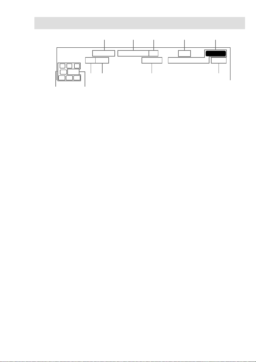
Parts Identification
The items are arranged in alphabetical order.
Refer to the pages indicated in parentheses ( ) for details.
Main unit
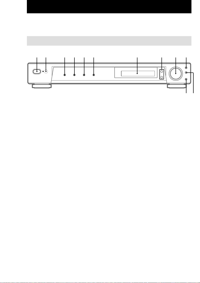
1 2 3 4 5 6 7 9 q;
Display 7 (20)
DVD 4 (17)
IR receptor 2
MASTER VOLUME 9 (17)
MUTING qs (17)
PLII q; (19)
PRESET TUNING +/– 8 (24)
SOUND FIELD qa (18, 21)
TUNER 6 (17, 23, 24)
TV/SAT 5 (17)
VIDEO 3 (17)
?/1 (power) 1 (12, 16, 17, 22)
8
qs qa
GB
4
Page 5
Hooking Up the Components
Required cords
Before you get started
• Turn off the power to all components before making any connections.
• Do not connect the AC power cord until all of the connections are completed.
• Be sure to make connections firmly to avoid hum and noise.
• When connecting optical digital cords, insert the cord plugs straight in until they click into place.
• Do not bend or tie the optical digital cord.
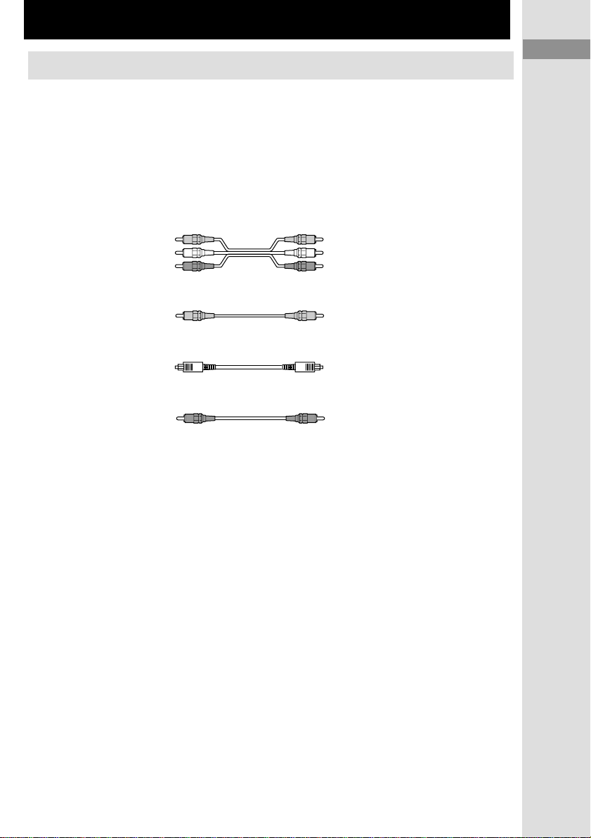
A Audio/video cord (not supplied)
Yellow (video) Yellow (video)
White (L/audio) White (L/audio)
Red (R/audio) Red (R/audio)
Hooking Up the Components
Parts Identification/Hooking Up the Components
B Video cord (not supplied)
C Optical digital cord (not supplied)
D Coaxial digital cord (not supplied)
Yellow (video) Yellow (video)
GB
GB
5
5
Page 6
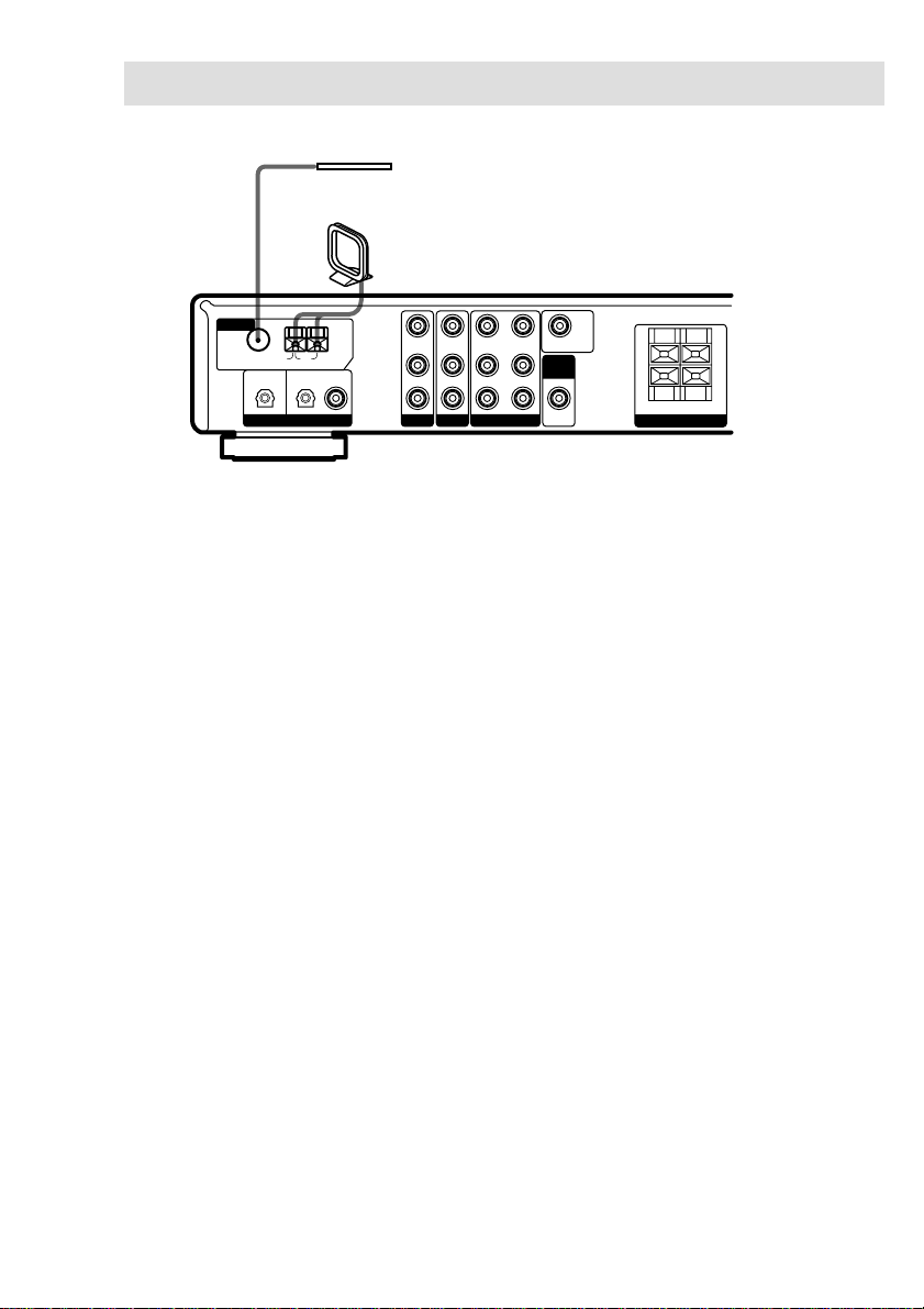
Antenna hookups
FM wire antenna
(supplied)
AM loop antenna
(supplied)
ANTENNA
75Ω COAXIAL
TV/SAT
U
AM
FM
OPTICAL IN OPTICAL IN
DIGITAL
DVD
COAX IN
VIDEO IN
VIDEO IN VIDEO OUT VIDEO IN MONITOR OUT
L
IN IN INOUT
R
DVDTV/
SAT
Notes on antenna hookups
• To prevent noise pickup, keep the AM loop
antenna away from the receiver and other
components.
• Be sure to fully extend the FM wire antenna.
• After connecting the FM wire antenna, keep it
as horizontal as possible.
• Do not use the U SIGNAL GND terminal for
grounding the receiver.
VIDEO
SUB
WOOFER
OUT
IMPEDANCE USE 8–16
+
–
R–FRONT–L
SPEAKERS
Ω
+
–
GB
6
Page 7
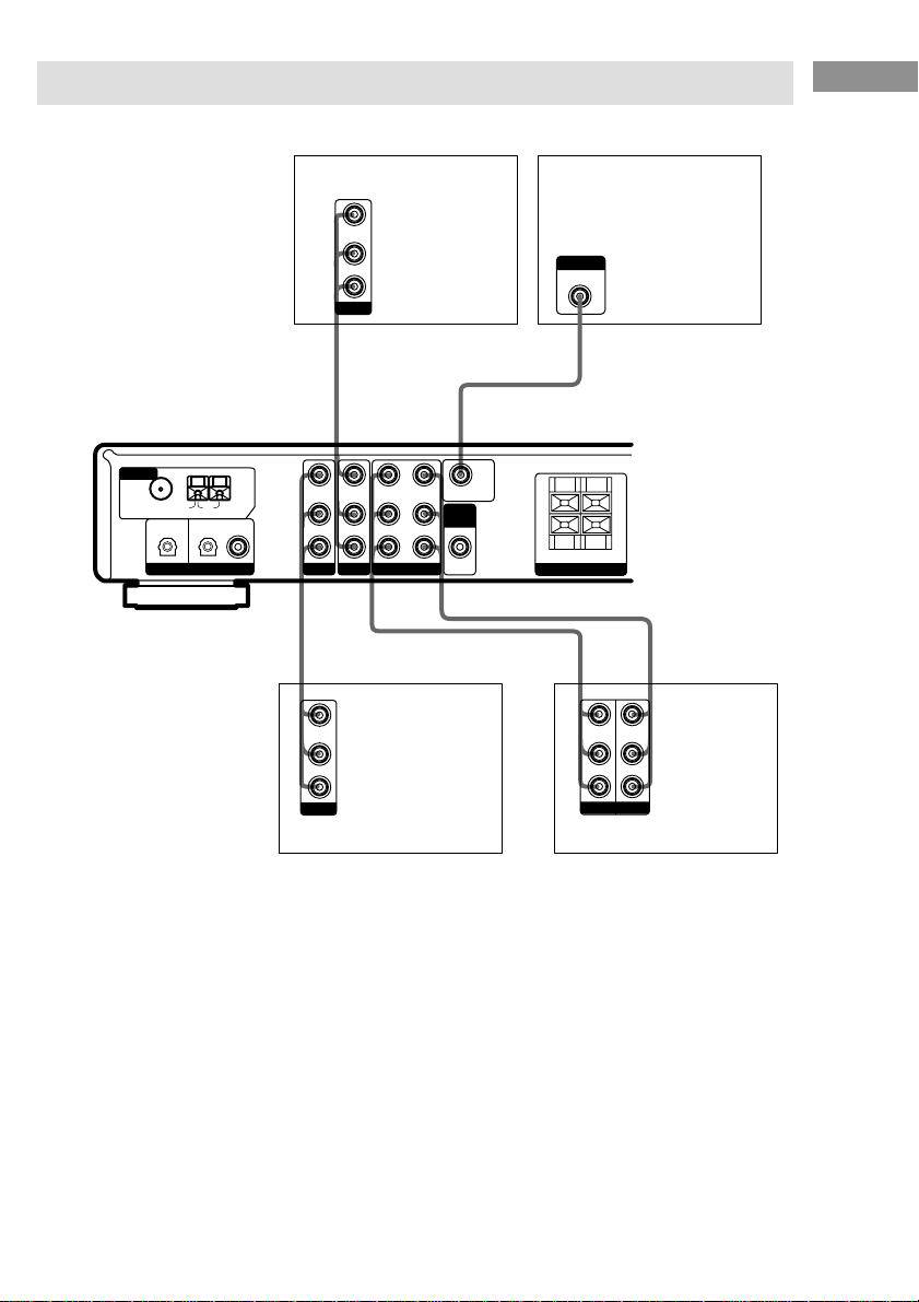
Video component hookups
For details on the required cords (A – D), see page 5.
Hooking Up the Components
ANTENNA
75Ω COAXIAL
TV/SAT
U
AM
FM
OPTICAL IN OPTICAL IN
DIGITAL
INPUT
MONITOR IN
TV monitor
DVD player
VIDEO OUT
L
AUDIO OUT
R
OUTPUT
BA
IMPEDANCE USE 8–16
VIDEO IN
VIDEO IN VIDEO OUT VIDEO IN MONITOR OUT
DVD
COAX IN
L
IN IN INOUT
R
SAT
DVDTV/
VIDEO
SUB
WOOFER
OUT
+
–
AAA
VIDEO OUT
L
AUDIO OUT
R
OUTPUT
Digital satellite tuner
R–FRONT–L
SPEAKERS
Ç
VIDEO IN
L
AUDIO IN
R
INPUT
Ω
+
–
VIDEO OUT
AUDIO OUT
OUTPUT
Ç
VCR
INOUT
GB
7
Page 8
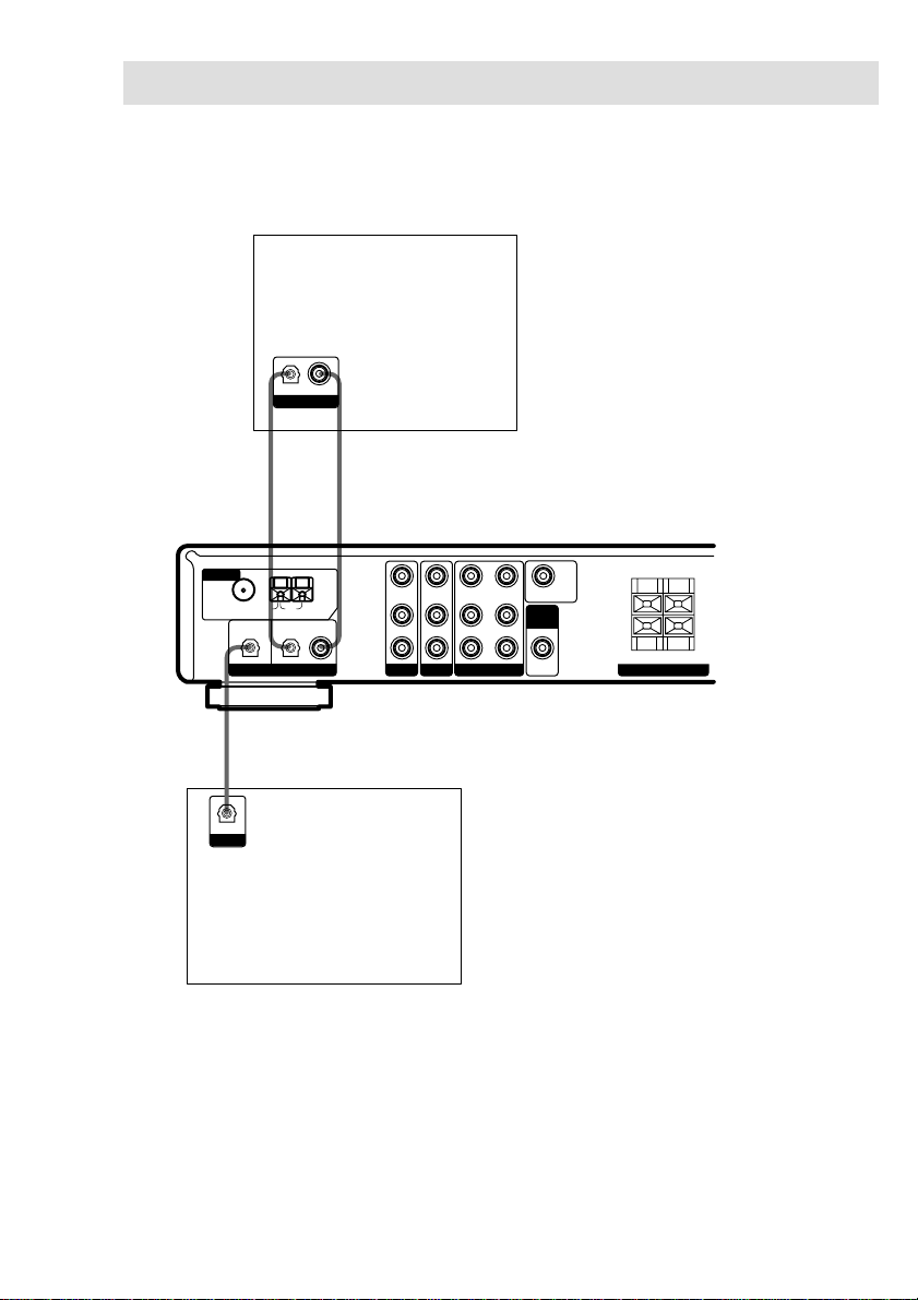
Digital component hookups
Connect the digital output jacks of your DVD player (etc.) to the receiver’s digital input jacks to
bring the multi channel surround sound of a movie theater into your home. To fully enjoy multi
channel surround sound, five speakers (two front speakers, two surround speakers, and a center
speaker) and a sub woofer are required.
DVD player (etc.)
OPTICAL COAXIAL
OUTPUT
C
*
*
D
ANTENNA
75Ω COAXIAL
TV/SAT
U
AM
FM
OPTICAL IN OPTICAL IN
DIGITAL
IMPEDANCE USE 8–16
VIDEO IN
VIDEO IN VIDEO OUT VIDEO IN MONITOR OUT
DVD
COAX IN
L
IN IN INOUT
R
SAT
DVDTV/
VIDEO
SUB
WOOFER
OUT
+
–
R–FRONT–L
SPEAKERS
Ω
+
–
C
OPTICAL
OUTPUT
Digital satellite
tuner (etc.)
* Connect to either the COAX or OPTICAL jack. We recommend making connections to the COAX jack.
Notes
• The OPTICAL and COAX input jacks are compatible with 96 kHz, 48 kHz, 44.1 kHz and 32 kHz sampling
frequencies.
• To playback the multi channel surround sound through this receiver, you may have to change the digital output
setting on the connected component. For details, refer to the operating instructions supplied with the component.
GB
8
Page 9
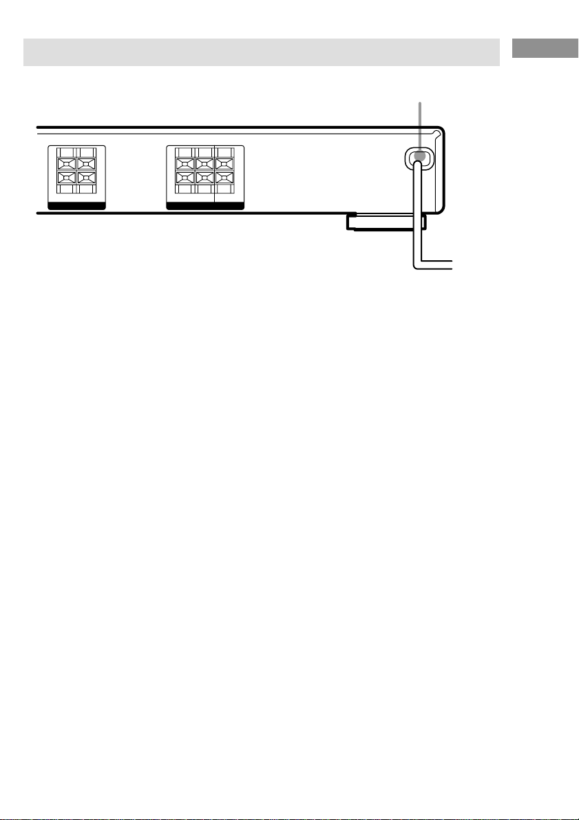
Other hookups
Hooking Up the Components
AC power cord
IMPEDANCE USE 8–16
+
–
R–FRONT–L
SPEAKERS
Ω
+
–
IMPEDANCE USE 8–16
+
–
R–SURR–L CENTER
SPEAKERS
Connecting the AC power
cord
Before connecting the AC power cord of this
receiver to a wall outlet, connect the speaker
system to the receiver (see page 10).
Connect the AC power cord(s) of your audio/
video components to a wall outlet.
Ω
+
–
b
To a wall outlet
GB
9
Page 10
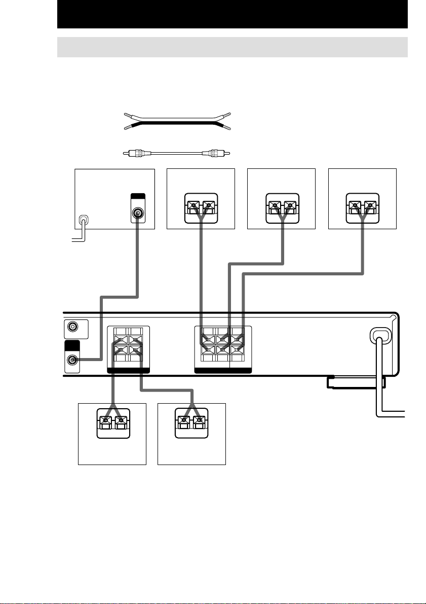
Hooking Up and Setting Up the Speaker System
Speaker system hookups
Before connecting speakers, be sure to turn off this unit.
Required cords
A Speaker cords (not supplied)
B Monaural audio cord (not supplied)
(+) (+)
(–)(–)
Black Black
Active sub woofer
b
To a wall outlet
(Switch the power to
off before connecting
the power cord.)
IMPEDANCE USE 8–16
MONITOR OUT
SUB
WOOFER
OUT
+
–
SPEAKERS
E
Surround speaker
(R)
INPUT
AUDIO
IN
BA A A
Ω
+
–
R–FRONT–L
e
EeEe
E
IMPEDANCE USE 8–16
+
–
R–SURR–L CENTER
SPEAKERS
AA
Ω
e
(L)
E
+
–
Center speakerSurround speaker
e
Front speaker (L)Front speaker (R)
10
GB
Page 11
Notes
• Twist the stripped ends of the speaker cords about
10 mm. Be sure to match the speaker cord to the
appropriate terminal on the components: + to + and
– to –. If the cords are reversed, the sound will be
distorted and will lack bass.
• If you use speakers with low maximum input rating,
adjust the volume carefully to avoid excessive
output on the speakers.
To avoid short-circuiting the
speakers
Short-circuiting of the speakers may damage
the receiver. To prevent this, make sure to take
the following precautions when connecting the
speakers.
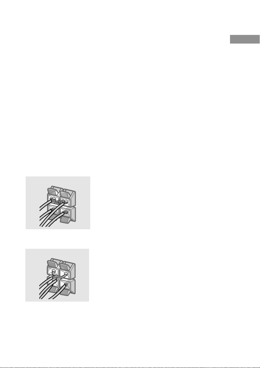
Make sure the stripped ends of each
speaker cord does not touch another
speaker terminal, the stripped end of
another speaker cord, or the metal parts of
the receiver.
Examples of poor conditions of the
speaker cord
After connecting all the components,
speakers, and AC power cord, output
a test tone to check that all the
speakers are connected correctly.
For details on outputting a test tone,
see page 16.
If no sound is heard from a speaker while
outputting a test tone or a test tone is output
from a speaker other than the one whose name
is currently displayed on the receiver, the
speaker may be short-circuited. If this happens,
check the speaker connection again.
To avoid damaging your
speakers
Make sure that you turn down the volume
before you turn off the receiver. When you turn
on the receiver, the volume remains at the level
you turn off the receiver.
Hooking Up and Setting Up the Speaker System
Stripped speaker cord is touching another
speaker terminal.
Stripped cords are touching each other
due to excessive removal of insulation.
11
GB
Page 12
Performing initial setup
45°
90°
20°
B
CC
AA
Multi channel surround
operations
Once you have hooked up the speakers and
turned on the power, clear the receiver’s
memory. Then specify the speaker parameters
(size, position, etc.) and perform any other
initial setup operations necessary for your
system.
Tip
To check the audio output during settings (to set up
while outputting the sound), check the connection
(see page 17).
Clearing the receiver’s
memory
Before using your receiver for the first time, or
when you want to clear the receiver’s memory,
do the following.
1 Turn off the receiver.
2 Hold down ?/1 for 5 seconds.
All of the following items are reset or
cleared:
• All sound field parameters are reset to
their factory settings.
• All SET UP parameters are reset to
their factory settings.
• The sound fields memorized for each
program source and preset stations are
cleared.
• The master volume is set to “MIN”.
• The fan control is set to “FAN ON”.
setup
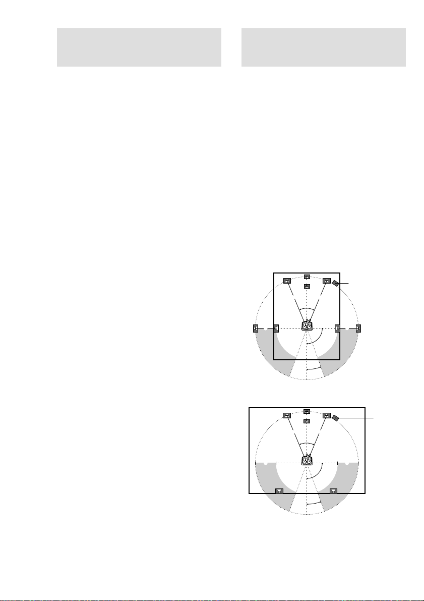
For the best possible surround sound, all
speakers should be the same distance from the
listening position (A).
However, the receiver lets you to place the
center speaker up to 1.5 meters closer (B) and
the surround speakers up to 4.5 meters closer
(C) to the listening position.
The front speakers can be placed from 1.0 to
12.0 meters from the listening position (A).
You can place the surround speakers either
behind you or to the side, depending on the
shape of your room (etc.).
Place the sub woofer at the same distance from
the listening position as the front speaker (left
or right).
When placing surround speakers to your side
Sub woofer
When placing surround speakers behind you
GB
12
Performing initial setup
operations
Before using your receiver for the first time,
adjust MAIN MENU parameters so that the
receiver correspond to your system. For the
adjustable parameters, see the table on page 31.
See pages 13–16 for speaker settings and pages
25–26 for other settings.
B
AA
45°
CC
90°
20°
Note
Do not place the center speaker farther away from the
listening position than the front speakers.
Sub woofer
Page 13
Specifying the speaker
parameters
1 Press MAIN MENU repeatedly to select
the SET UP menu.
2 Move the V/v/B/b button up or down
to select the parameter you want to
adjust.
3 Move the V/v/B/b button to left or
right to select the setting you want.
4 Repeat steps 2 to 3 until you have set
all of the parameters that follow.
Initial settings
Parameter Initial setting
L
R (FRONT) LARGE
C
(CENTER) LARGE
SL
SR (SURR) LARGE
SW
S.W. XXX (SUB WOOFER) YES
L
R DIST. XX.X m 5.0 m
C
DIST. XX.X m 5.0 m
SL
SR DIST. XX.X m 5.0 m
SL
SR PL. XXX BEHD.
SL
SR HGT. XXX LOW
Tips for the speaker settings
When you use micro satellite speaker system, you can
easily adjust the settings for the speaker size and sub
woofer selection. Turn off the power, then turn on
again while pressing the MUTING button. “MICRO
SP.” appears in the display and the speaker size and
the sub woofer selection are fixed to the following
settings.
Speakers Settings
Front SMALL
Center SMALL
Surround SMALL
Sub woofer YES
You cannot change the configuration if you choose
MICRO SP.
To reset to the normal settings, turn off the power,
then turn on again while pressing the MUTING
button.
x Front speaker size (L R)
• If you connect large speakers that will
effectively reproduce bass frequencies, select
“LARGE”.
• If the sound is distorted, or you feel a lack of
surround effects when using multi channel
surround sound, select “SMALL” to activate
the bass redirection circuitry and output the
front channel bass frequencies from the sub
woofer.
• When the front speakers are set to “SMALL”,
the center and surround speakers are also
automatically set to “SMALL” (unless
previously set to “NO”).
Hooking Up and Setting Up the Speaker System
continued
13
GB
Page 14

Multi channel surround setup
(continued)
x Center speaker size (C)
• If you connect a large speaker that will
effectively reproduce bass frequencies, select
“LARGE”. However, if the front speakers are
set to “SMALL”, you cannot set the center
speaker to “LARGE”.
• If the sound is distorted, or you feel a lack of
surround effects when using multi channel
surround sound, select “SMALL” to activate
the bass redirection circuitry and output the
center channel bass frequencies from the front
speakers (if set to “LARGE”) or sub woofer.*
• If you do not connect a center speaker, select
“NO”. The sound of the center channel will be
output from the front speakers.*
x Surround speaker size (SL SR)
• If you connect large speakers that will
effectively reproduce bass frequencies, select
“LARGE”. However, if the front speakers are
set to “SMALL”, you cannot set the surround
speakers to “LARGE”.
• If the sound is distorted, or you feel a lack of
surround effects when using multi channel
surround sound, select “SMALL” to activate
the bass redirection circuitry and output the
surround channel bass frequencies from the sub
woofer or other “LARGE” speakers.
• If you do not connect surround speakers, select
Tip
*1–*3 correspond to the following Dolby Pro Logic
modes
*1 NORMAL
*2 PHANTOM
*3 3 STEREO
“NO”.*
3
2
Tip
Internally, the LARGE and SMALL settings for each
speaker determine whether or not the internal sound
processor will cut the bass signal from that channel.
When the bass is cut from a channel, the bass
redirection circuitry sends the corresponding bass
frequencies to the sub woofer or other “LARGE”
speakers.
However, since bass sounds have a certain amount of
directionality, it best not to cut them, if possible.
Therefore, even when using small speakers, you can
set them to “LARGE” if you want to output the bass
frequencies from that speaker. On the other hand, if
you are using a large speaker, but prefer not to have
bass frequencies output from that speaker, set it to
“SMALL”.
1
If the overall sound level is lower than you prefer, set
all speakers to “LARGE”.
x Sub woofer selection (SW S.W. XXX)
•
If you connect a sub woofer, select “YES”.
• If you do not connect a sub woofer, select
“NO”. This activates the bass redirection
circuitry and outputs the LFE signals from other
speakers.
• In order to take full advantage of the Dolby
Digital bass redirection circuitry, we
recommend setting the sub woofer’s cut off
frequency as high as possible.
14
GB
Page 15
x Front speaker distance
(L R DIST. XX.X m)
Set the distance from your listening position to
the front speakers (A on page 12).
x Center speaker distance
(C DIST. XX.X m)
Set the distance from your listening position to
the center speaker. Center speaker distance
should be set from a distance equal to the front
speaker distance (A on page 12) to a distance
1.5 meters closer to your listening position (B
on page 12).
x Surround speaker distance
(SL SR DIST. XX.X m)
Set the distance from your listening position to
the surround speakers. Surround speaker
distance should be set from a distance equal to
the front speaker distance (A on page 12) to a
distance 4.5 meters closer to your listening
position (C on page 12).
Tip
The receiver allows you to input the speaker position
in terms of distance. However, it is not possible to set
the center speaker further than the front speakers.
Also, the center speaker cannot be set more than
1.5 meters closer than the front speakers.
Likewise, the surround speakers can not be set farther
away from the listening position than the front
speakers. And they can be no more than 4.5 meters
closer.
This is because incorrect speaker placement is not
conducive to the enjoyment of surround sound.
Please note that, setting the speaker distance closer
than the actual location of the speakers will cause a
delay in the output of the sound from that speaker. In
other words, the speaker will sound like it is farther
away.
For example, setting the center speaker distance
1–2 m closer than the actual speaker position will
create a fairly realistic sensation of being “inside” the
screen. If you cannot obtain a satisfactory surround
effect because the surround speakers are too close,
setting the surround speaker distance closer (shorter)
than the actual distance will create a larger sound
stage.
Adjusting these parameter while listening to the
sound often results in much better surround sound.
Give it a try!
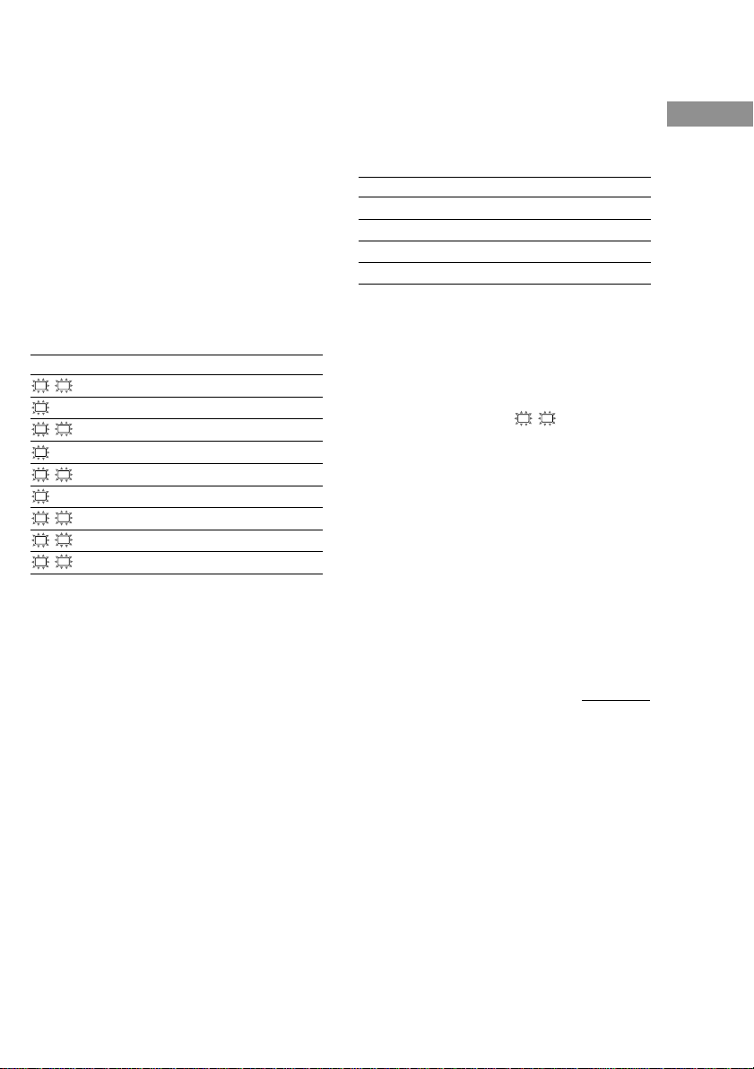
x Surround speaker position
(SL SR PL. XXX)*
This parameter lets you specify the location of
your surround speakers. Refer to the illustration
below.
• Select “SIDE” if the location of your surround
speakers corresponds to section A.
• Select “MID” if the location of your surround
speakers corresponds to section B.
• Select “BEHD.” if the location of your
surround speakers corresponds to section C.
90°
A
B
C C
A
60°
30°
B
20°
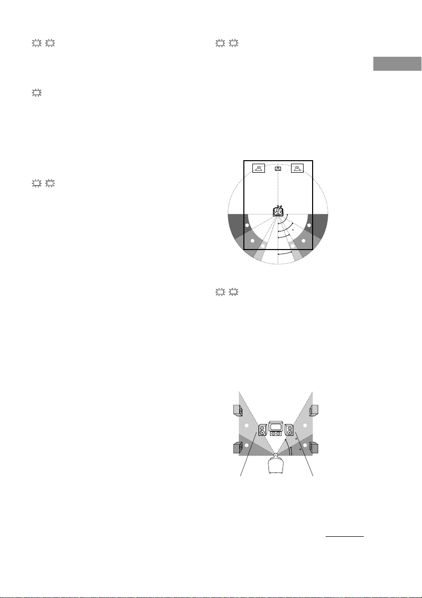
x Surround speaker height
(SL SR HGT. XXX)*
This parameter lets you specify the height of
your surround speakers. Refer to the illustration
below.
• Select “LOW” if the location of your surround
speakers corresponds to section A.
• Select “HIGH” if the location of your surround
speakers corresponds to section B.
B
A
B
60
A
30
* These parameters are not available when
“Surround speaker size” is set to “NO”.
Hooking Up and Setting Up the Speaker System
continued
15
GB
Page 16

Multi channel surround setup
(continued)
Adjusting the speaker level
Use the remote while seated in your listening
position to adjust the level of each speaker.
1 Press ?/1 to turn on the receiver.
2 Turn MASTER VOLUME on the receiver
clockwise.
3 Turn on the power of the sub woofer.
4 Press TEST TONE.
You will hear the test tone from each
speaker in sequence.
Front (left) t Center t Front (right) t
Surround (right) t Surround (left) t
Sub woofer
5 Adjust the level parameters so that the
level of the test tone from each speaker
sounds the same when you are in your
main listening position.
To adjust the balance and level of speakers,
press MAIN MENU repeatedly to select
LEVEL menu, move the
or down to select the parameter you want to
adjust (page 21). Then move the
button to left or right to select the setting, and
press the button to enter the selection.
V/v/B/b
V/v/B/b
button up
6 Press TEST TONE again to turn off the
test tone.
Tip
You can adjust the level of all speakers at the same
time. Turn MASTER VOLUME on the main unit or
press MASTER VOL +/– on the remote.
Notes
• The front balance, center level, surround level, and
sub woofer level are shown in the display during
adjustment.
• To enjoy the better sound quality, do not turn the
volume of the subwoofer too high.
16
GB
Page 17

Basic Operations
Checking the connections
After connecting all of your components to the
receiver, do the following to verify that the
connections were made correctly.
1 Press ?/1 to turn on the receiver.
2 Press a function button to select a
component (program source) that you
connected (e.g., DVD player).
3 Turn on the component and start
playing it.
4 Rotate MASTER VOLUME to turn up the
volume.
If you do not obtain normal sound output after
performing this procedure, see
“Troubleshooting” on page 27 and take the
appropriate measures to correct the problem.
Switching the setting of fan control
Hold down PLII button and press ?/1 to change the
fan control setup. Each time you do the procedure
above, the following setup appears.
Select To
FAN ON* Turn on the fan at all times.
FAN AUTO Turn on the fan automatically
when there is sufficient speaker
output.
* Initial setting.
Selecting the component
Function buttons
Press a function button to select the component
you want to use.
To select Press
VCR VIDEO
DVD player DVD
TV or digital TV/SAT
satellite tuner (etc.)
Tuner TUNER
After turning on the component you selected,
select the component and play the program
source.
MUTING
Press MUTING to mute the sound. MUTING
appears on the display when the sound is
muted. To cancel muting, press it again or turn
up the volume.
The muting function is also canceled when
turning the power off, or disconnecting the
power cord.
Hooking Up and Setting Up the Speaker System
Basic Operations
17
GB
Page 18

Enjoying Surround Sound
You can take advantage of surround sound
simply by selecting one of the receiver’s preprogrammed sound fields. They bring the
exciting and powerful sound of movie theaters
and concert halls into your home. You can also
customize the sound fields to obtain the sound
you want by changing the various surround
parameters.
To fully enjoy surround sound, you must
register the number and location of you
speakers. See “Multi channel surround setup”
starting from page 12 to set the speaker
parameters before enjoying surround sound.
Selecting a sound field
You can enjoy surround sound simply by
selecting one of the pre-programmed sound
fields according to the program you want to
listen to.
Press SOUND FIELD +/– repeatedly to
select the sound field you want.
The current sound field is indicated in the
display. See pages 18–19 for information on
each sound field.
To turn the surround effect off
Press AUTO DEC, or select 2CH ST.
Tips
• The receiver memorizes the last sound field selected
for each program source (Sound Field Link).
Whenever you select a program source, the sound
field that was last applied is automatically applied
again. For example, if you listen to DVD with
HALL as the sound field, change to a different
program source, then return to DVD, HALL will be
applied again.
• You can identify the encoding format of program
software by looking at its packaging.
Dolby Digital discs are labeled with the
logo, and Dolby Surround encoded programs are
labeled with the logo.
About DCS (Digital Cinema Sound)
DCS
DCS is the concept name of the surround
technology for home theater developed by
Sony. DCS uses the DSP (Digital Signal
Processor) technology to reproduce the sound
characteristics of an actual cinema cutting
studio in Hollywood.
When played at home, DCS will create a
powerful theater effect that mimics the artistic
combination of sound and action as envisioned
by the movie director.
x AUTO DEC
Automatically detects the type of audio signal
being input (Dolby Digital, DTS, or standard 2
channel stereo) and performs the proper
decoding if necessary. This mode presents the
sound as it was recorded/encoded, without
adding any effects (ex. reverberation).
x 2CH ST.
Outputs the sound from the front left and right
speakers only. Standard 2 channel (stereo)
sources completely bypass the sound field
processing. Multi channel surround formats are
downmixed to 2 channel.
x NORM.SURR. (Normal Surround)
Software with multi channel surround audio
signals is played back according to the way it
was recorded. Software with 2 channel audio
signals is decoded with Dolby Pro Logic (II) to
create surround effects.
x C.ST.EX A–C DCS
• C.ST.EX A reproduces the sound
characteristics of Sony Pictures Entertainment’s
classic editing studio.
• C.ST.EX B reproduces the sound characteristics
of Sony Pictures Entertainment’s mixing studio
which is one of the most up-to-date facilities in
Hollywood.
• C.ST.EX C reproduces the sound characteristics
of Sony Pictures Entertainment’s BGM
recording studio.
18
GB
Page 19

x HALL
Reproduces the acoustics of a rectangular
concert hall.
x JAZZ (Jazz Club)
Reproduces the acoustics of a jazz club.
x CONCERT (Live Concert)
Reproduces the acoustics of a 300-seat live
house.
x GAME
Obtains maximum audio impact from video
game software.
Notes
• No sound is output from the sub woofer when
“2CH ST.” is selected. To listen to 2 channel
(stereo) sources using the front left and right
speakers and a sub woofer, select “AUTO DEC”.
• When you select MICRO SP., internal sound
processor will automatically redirect bass sound to
subwoofer.
Enjoying Dolby Pro Logic II
(2CH MODE)
This function lets you specify the type of
decoding for 2 channel audio sources.
This receiver can reproduce 2 channel sound in
5 channels through Dolby Pro Logic II; or 4
channels through Dolby Pro Logic.
Press ;PL/PLII repeatedly to select the
2 channel decoding mode.
The selected mode appears in the display. The
sound field automatically switches to
“NORM.SURR.” (page 18).
•“DOLBY PL” performs Pro Logic decoding.
The source recorded in 2 channel is decoded
into 4.1 channels.
•“II MOVIE” performs Pro Logic II Movie
mode decoding. This setting is ideal for movies
encoded in Dolby Surround. In Addition, this
mode can reproduce sound in 5.1 channel when
watching videos of overdubbed or old movies.
•“II MUSIC” performs the Pro Logic II Music
mode decoding. This setting is ideal for normal
stereo sources such as CDs.
Tip
You can also use PLII on the receiver to select the 2
channel decoding mode.
Enjoying Surround Sound
19
GB
Page 20
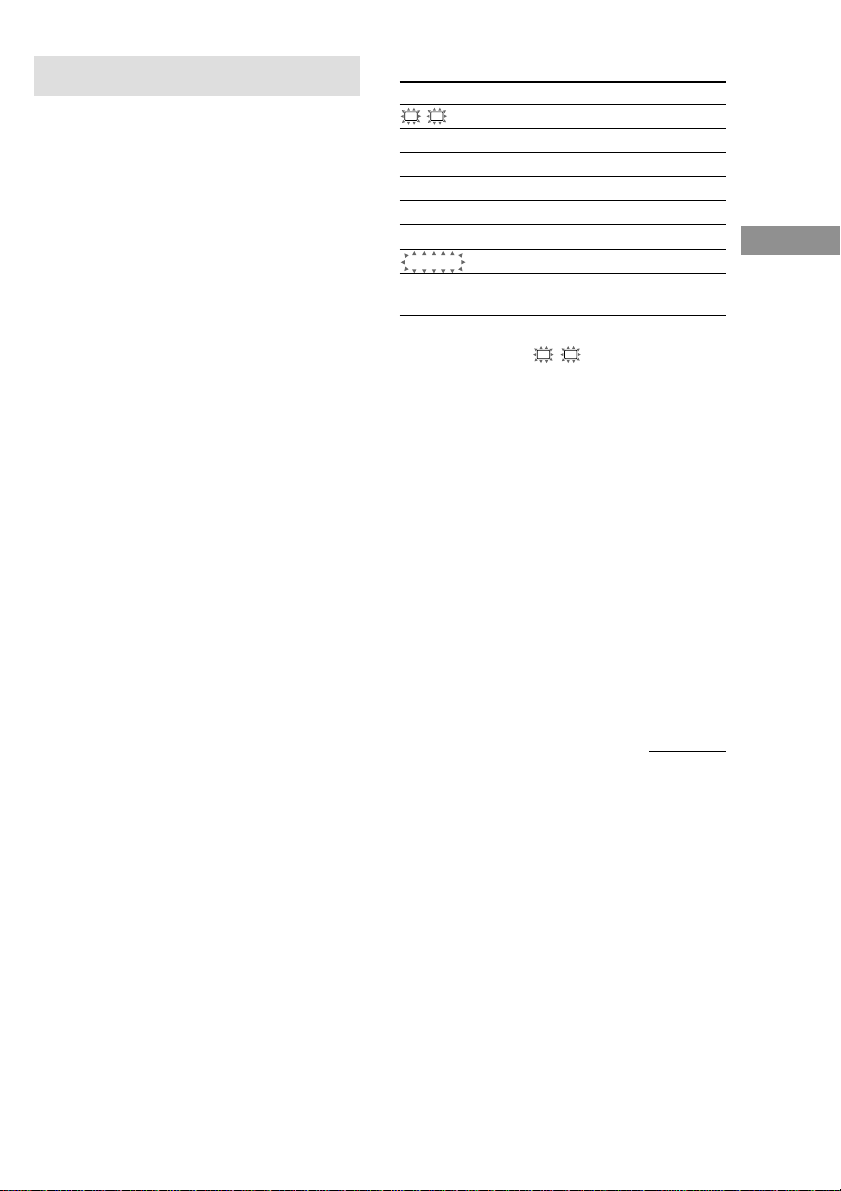
Understanding the multi channel surround displays
1 2 3 4 5
L CR
SW
SL
qa
L F E
S SR
DIGITALaPRO LOGIC II
COAX
OPT
0
a
1 ; DIGITAL: Lights up when the receiver is
decoding signals recorded in the Dolby
Digital format.
2 ; PRO LOGIC II: “PRO LOGIC” lights up
when a 2-channel signal is applied with
“DOLBY PL” or C.ST.EX A–C. “PRO
LOGIC II” lights up when a 2-channel signal
is set to “II MOVIE” or “II MUSIC”.
However, this indicator does not light if the
center and surround speakers are set to “NO”,
and “AUTO DEC” or “NORM. SURR.” is
selected.
3 DTS: Lights up when DTS signals are input.
4 MPEG: Lights up when MPEG signals are
input.
Note
Only the front 2 channels are compatible with
MPEG format. Multi channel surround sound is
downmixed and output from the front 2 channels.
5 Tuner indicators: Light up when using the
receiver to tune in radio stations, etc. See
pages 23–24 for tuner operations.
6 SLEEP: Lights up when sleep timer is
activated.
DTS MPEG
D.RANGE
STEREO MONO
MEMORY
SLEEP
78 69
7 D.RANGE: Lights up when dynamic range
compression is activated. See page 22 to
adjust the dynamic range compression.
8 COAX: Lights up when the source signal is a
digital signal being input through the COAX
terminal.
9 OPT: Lights up when the source signal is a
digital signal being input through the
OPTICAL terminal.
0 LFE: Lights up when the disc being played
back contains the LFE (Low Frequency
Effect) channel and when the sound of the
LFE channel signal is actually being
reproduced.
qa Playback channel indicators: The letters
light up to indicate the channels being played
back.
L (Front Left), R (Front Right), C (Center
(monaural)), SL (Surround Left), SR
(Surround Right), S (Surround (monaural or
the surround components obtained by Pro
Logic processing)), SW (Sub woofer)
The boxes around the letters light up to
indicate the speakers used to playback the
channels.
20
GB
Page 21
Customizing sound fields
By adjusting the level parameters, you can
customize the sound fields to suit your
particular listening situation.
Once you customize a sound field, the changes
are stored in the memory indefinitely. You can
change a customized sound field any time by
making new adjustments to the parameters.
See the tables on page 32 for the parameters
available in each sound field.
Initial settings
Parameter Initial setting
L
R BAL. L/R XXX BALANCE
CTR XXX dB 0 dB
SUR.L. XXX dB 0 dB
SUR.R. XXX dB 0 dB
S.W. XXX dB 0 dB
L.F.E. XXX dB 0 dB
COMP. XXX OFF
D. RANGE
EFFECT (depends on the
sound field)
Enjoying Surround Sound
To get the most from multi
channel surround sound
Position your speakers and do the procedures
described in “Multi channel surround setup”
starting from page 12 before you customize a
sound field.
Adjusting the level
parameters
The LEVEL menu contains parameters that let
you adjust the balance and volumes of each
speaker. The settings are applied to all sound
fields.
1 Start playing a program source
encoded with multi channel surround
sound.
2 Press MAIN MENU repeatedly to select
the LEVEL menu.
3 Move the V/v/B/b button up or down
to select the parameter you want to
adjust.
4 Move the V/v/B/b button to left or
right to select the setting you want.
Front balance (L R BAL. L/R XXX)
Lets you adjust the balance between front left
and right speakers.
Center level (CTR XXX dB)
Lets you adjust the level of the center speaker.
Surround (left) level
(SUR.L. XXX dB)
Lets you adjust the level of the left surround
speaker.
Surround (right) level
(SUR.R. XXX dB)
Lets you adjust the level of the right surround
speaker.
Sub woofer level (S.W. XXX dB)
Lets you adjust the level of the sub woofer.
continued
21
GB
Page 22

Customizing sound fields
(continued)
Low Frequency Effect
(L.F.E. XXX dB)
Lets you attenuate the level of the LFE (Low
Frequency Effect) channel output from the sub
woofer without effecting the level of the bass
frequencies sent to the sub woofer from the
front, center or surround channels via the
Dolby Digital or DTS bass redirection
circuitry.
•“0 dB” outputs the full LFE signal at the mix
level determined by the recording engineer.
• To mute the sound of the LFE channel from the
sub woofer, select “OFF”. However, the low
frequency sounds of the front, center, or
surround speakers are output from the sub
woofer according to the settings made for each
speaker in the speaker setup (pages 14–15).
Dynamic range compressor
(
D. RANGE
Lets you compress the dynamic range of the
sound track. This may be useful when you want
to watch movies at low volumes late at night.
We recommend using the “MAX” setting.
• To reproduce the sound track with no
• To reproduce the sound track with the dynamic
• To compress the dynamic range in small steps
• To reproduce a dramatic compression of the
Effect level (EFFECT)
Lets you adjust the “presence” of the current
surround effect.
COMP. XXX)
compression, select “OFF”.
range intended by the recording engineer, select
“STD”.
to achieve the sound you desire, select “0.1”–
“0.9”.
dynamic range, select “MAX”.
Adjusting the tone
parameters
The TONE menu contains parameters that let
you adjust the bass and treble. The settings are
stored individually for each sound field.
1 Start playing a program source
encoded with multi channel surround
sound.
2 Press MAIN MENU repeatedly to select
the TONE menu.
3 Move the V/v/B/b button up or down
to select the parameter you want to
adjust.
4 Move the V/v/B/b button to left or
right to select the setting you want.
Initial settings
Parameter Initial setting
BASS 0 dB
TREB. 0 dB
Bass adjustment (BASS)
Lets you adjust the gain of the bass.
Treble adjustment (TREB.)
Lets you adjust the gain of the treble.
Resetting customized sound
fields to the factory settings
1 If the power is on, press ?/1 to turn off
the power.
2 Hold down SOUND FIELD and press
?/1.
“S.F. CLR.” appears in the display and all
sound fields are reset at once.
22
GB
Page 23

Receiving Broadcasts
Before receiving broadcasts, make sure you
have connected FM and AM antennas to the
receiver (see page 6).
Use the remote for the tuner operation.
Direct tuning
You can enter a frequency of the station you
want directly by using the numeric buttons on
the supplied remote.
1 Press TUNER.
The last received station is tuned in.
2 Press TUNER when you change the FM
or AM band.
3 Press D.TUNING
4 Press the numeric buttons to enter the
frequency.
Example 1: FM 102.50 MHz
bbbb
1 0 2 5 0
Example 2: AM 1350 kHz
bbb
1 3 5 0
If you cannot tune in a station and the
entered numbers flash
Make sure you’ve entered the right
frequency. If not, repeat steps 3 and 4.
If the entered numbers still flash, the
frequency is not used in your area.
5 If you’ve tuned in an AM station, adjust
the direction of the AM loop antenna for
optimum reception.
6 Repeat steps 2 to 5 to receive another
station.
Tips
• If you do not remember the precise frequency, press
TUNING + or TUNING – after entering the value
close to the frequency you want. The receiver
automatically tunes in the station you want. If the
frequency seems to be higher than the entered value,
press TUNING +, and if the frequency seems to be
lower than the entered value, press
TUNING –.
• If “STEREO” flashes in the display and the FM
stereo reception is poor, press FM MODE to
improve the sound. You will not be able to enjoy the
stereo effect, but the sound will be less distorted.
Note
If “STEREO” does not appear at all when an FM
broadcast is received normally, press FM MODE to
turn on the “STEREO” indication.
Automatic tuning
If you don’t know the frequency of the station
you want, you can let the receiver scan all
available stations in your area.
1 Press TUNER.
The last received station is tuned in.
2 Press TUNER when you change the FM
or AM band.
3 Press TUNING + or TUNING –.
Press TUNING + to scan from low to high;
press TUNING – to scan from high to low.
The receiver stops scanning whenever a
station is received.
When the receiver reaches either end of
the band
Scanning is repeated in the same direction.
4 To continue scanning, press TUNING +
or TUNING – again.
Receiving Broadcasts
23
GB
Page 24

Preset tuning
After you have tuned in stations using Direct
Tuning or Automatic Tuning, you can preset
them to the receiver. Then you can tune in any
of the stations directly by entering its
2-character preset code using the supplied
remote. Up to 30 FM or AM stations can be
preset. The receiver will also scan all the
stations that you have preset.
Before tuning to preset stations, be sure to
preset them by performing steps on “Presetting
radio stations”.
Presetting radio stations
1 Press TUNER.
The last received station is tuned in.
2 Tune in the station that you want to
preset using Direct Tuning or
Automatic Tuning (page 23).
3 Press MEMORY.
“MEMORY” appears in the display for a
few seconds.
Do steps 4 to 5 before “MEMORY” goes
out.
4 Press PRESET + or PRESET – to select
a preset number.
If “MEMORY” goes out before you press
the preset number, start again from step 3.
5 Press MEMORY again to store the
station.
If “MEMORY” goes out before you can
store the station, start again from step 3.
6 Repeat steps 2 to 5 to preset another
station.
Tuning to preset stations
You can tune the preset stations by either of the
following two ways.
Scanning the preset stations
1 Press TUNER.
The last received station is tuned in.
2 Press PRESET + or PRESET –
repeatedly to select the preset station
you want.
Each time you press the button, the receiver
tunes in one preset station at a time, in the
corresponding order and direction as
follows:
nA1˜A2˜...˜A0˜B1˜B2˜...˜B0N
nC0˜...C2˜C1N
Using the preset codes
Use the supplied remote to perform the
following operations. For details on the buttons
used in this section, see page 33–35.
1 Press TUNER.
The last received station is tuned in.
2 Press SHIFT to select a memory page
(A, B, or C), then press the preset
number of the station you want using
the numeric buttons.
Tip
You can also use PRESET TUNING +/– on the
receiver to tune to preset stations.
24
GB
Page 25

Other Operations
Using the Sleep Timer
You can set the receiver to turn off
automatically at a specified time.
After pressing ALT (page 35), press
SLEEP while the power is on.
Each time you press the button, the display
changes cyclically as follows:
2-00-00 t 1-30-00 t 1-00-00 t 0-30-00
t OFF
To specify the time freely
1 After pressing ALT (page 35), press SLEEP.
2 After pressing MAIN MENU (page 35), press
the V/v/B/b button to specify the time you
want.
The sleep timer changes in 1 minute intervals.
You can specify up to 5 hours.
Tip
To check the remaining time before the receiver turns
off, press SLEEP. The remaining time appears in the
display.
Adjustments using the
SET UP menu
The SET UP menu allows you to make the
following adjustments.
1 Press MAIN MENU repeatedly to select
the SET UP menu.
2 Move the V/v/B/b button up or down
to select the parameter you want to
adjust.
3 Move the V/v/B/b button to left or
right to select the setting you want.
4 Repeat steps 2 to 3 until you have set
all of the parameters that follow.
Initial settings
Parameter Initial setting
DVD-XXXX AUTO
TV-XXXX AUTO
x Audio input mode for DVD function
(DVD-XXXX)
Lets you select the audio input mode for DVD
function.
• “AUTO” gives priority to the analog audio
signals input to the DVD IN (L/R) jacks when
there is no digital audio signals.
• “COAX” specifies the digital audio signals
input to the DIGITAL DVD COAX input jacks.
• “OPT” specifies the digital audio signals input
to the DIGITAL DVD OPTICAL input jacks.
• “ANLG” specifies the analog audio signals
input to the DVD IN (L/R) jacks.
Other Operations
continued
25
GB
Page 26

Adjustments using the SET UP menu
(continued)
x Audio input mode for TV/SAT
function (TV-XXXX)
Lets you select the audio input mode for TV/
SAT function.
•“AUTO” gives priority to the analog audio
signals input to the TV/SAT IN (L/R) jacks
when there is no digital audio signals.
•“OPT” specifies the digital audio signals input
to the DIGITAL TV/SAT OPTICAL input
jacks.
•“ANLG” specifies the analog audio signals
input to the TV/SAT IN (L/R) jacks.
26
GB
Page 27

Additional Information
Precautions
On safety
Should any solid object or liquid fall into the cabinet,
unplug the receiver and have it checked by qualified
personnel before operating it any further.
On power sources
• Before operating the unit, check that the operating
voltage is identical with your local power supply.
The operating voltage is indicated on the nameplate
at the rear of the receiver.
• The unit is not disconnected from the AC power
source (mains) as long as it is connected to the wall
outlet, even if the receiver itself has been turned off.
• If you are not going to use the receiver for a long
time, be sure to disconnect the receiver from the
wall outlet. To disconnect the AC power cord,
grasp the plug itself; never pull the cord.
• AC power cord must be changed only at the
qualified service shop.
On heat buildup
• Although the unit heats up during operation, this is
not a malfunction. If you continuously use this unit
at a large volume, the cabinet temperature of the
top, side and bottom rises considerably. To avoid
burning yourself, do not touch the cabinet.
• For details about fan activation, see page 17.
On placement
• Place the receiver in a location with adequate
ventilation to prevent heat buildup and prolong the
life of the receiver.
• Do not place the receiver near heat sources, or in a
place subject to direct sunlight, excessive dust or
mechanical shock.
• Do not place anything on top of the cabinet that
might block the ventilation holes and cause
malfunctions.
On operation
Before connecting other components, be sure to turn
off and unplug the receiver.
On cleaning
Clean the cabinet, panel and controls with a soft cloth
slightly moistened with a mild detergent solution. Do
not use any type of abrasive pad, scouring powder or
solvent such as alcohol or benzine.
If you have any question or problem concerning your
receiver, please consult your nearest Sony dealer.
Troubleshooting
If you experience any of the following
difficulties while using the receiver, use this
troubleshooting guide to help you remedy the
problem. Also, see “Checking the connections”
on page 17 to verify that the connections are
correct. Should any problem persist, consult
your nearest Sony dealer.
There is no sound no matter which component
is selected.
• Check that both the receiver and all components
are turned on.
• Check that the MASTER VOLUME control is
not set at “MIN”.
• Check that all speaker cords are connected
correctly.
• Press MUTING to cancel the muting function.
There is no sound from a specific component.
• Check that the component is connected correctly
to the audio input jacks for that component.
• Check that the cord(s) used for the connection is
(are) fully inserted into the jacks on both the
receiver and the component.
There is no sound from one of the front
speakers.
• Check that the component is connected correctly
to the audio input jacks for that component.
• Check that the cord(s) used for the connection is
(are) fully inserted into the jacks on both the
receiver and the component.
The multi channel surround effect of the Dolby
Digital or DTS is not obtained.
• Check that the DVD software, etc. is recorded in
Dolby Digital or DTS.
• If you connect the DVD player, etc. to the digital
input jack on this system, check the audio setting
(for digital audio output) of the component.
• Check that the audio track is correctly selected
on the DVD player. (Check the audio setting of
the DVD menu.)
continued
Additional Information
27
GB
Page 28

Troubleshooting (continued)
There is no sound or only a very low-level sound
is heard.
• Check that the speakers and components are
connected securely.
• Check that you have selected the correct
component on the receiver.
• Press MUTING if muting function is activated.
• The protection circuit has been activated. Turn
off the receiver, eliminate the short-circuit
problem and turn on the power again after about
20 seconds.
The left and right sounds are unbalanced or
reversed.
• Check that the speakers and components are
connected correctly and securely.
• Adjust balance parameters in the LEVEL menu.
There is severe hum or noise.
• Check that the speakers and components are
connected securely.
• Check that the connecting cords are away from a
transformer or motor, and at least 3 meters away
from a TV set or fluorescent light.
• The plugs and jacks are dirty. Wipe them with a
cloth slightly moistened with alcohol.
There is no sound from the center speaker.
• Make sure the sound field function is on (press
SOUND FIELD +/–).
• Select C.ST.EX A–C (see page 18).
• Adjust the speaker level (see page 21).
• Make sure the center speaker size parameter is
not set to “NO” (see page 15).
There is no sound or only a very low-level sound
is heard from the surround speakers.
• Make sure the sound field function is on (press
SOUND FIELD +/–).
• Select C.ST.EX A–C (see page 18).
• Adjust the speaker level (see page 21).
• Make sure the surround speaker size parameter is
not set to “NO” (see page 15).
There is no sound from the active sub woofer.
• When you select NORM. SP., make sure the sub
woofer is set to “YES” (see page 15).
• Check that “2CH ST.” is not selected (see page
19).
Radio stations cannot be tuned in.
• Check that the antennas are connected securely.
Adjust the antennas and connect an external
antenna if necessary.
• The signal strength of the stations is too weak
(when tuning in with automatic tuning). Use
Direct tuning.
• No stations have been preset or the preset
stations have been cleared (when tuning by
scanning preset stations). Preset the stations (see
page 24).
The surround effect cannot be obtained.
• Make sure the sound field function is on (press
SOUND FIELD +/–).
There is no picture or an unclear picture appears
on the TV screen or monitor.
• Select the appropriate function on the receiver.
• Set your TV to the appropriate input mode.
The remote does not function.
• Point the remote at the remote sensor on the
receiver.
• Remove any obstacles in the path between the
remote and the receiver.
• Replace both batteries in the remote with new
ones, if they are weak.
• Make sure you select the correct function on the
remote.
Reference sections for clearing the
receiver’s memory
To clear See
All memorized settings page 12
Customized sound fields page 22
28
GB
Page 29

Specifications
Amplifier section
POWER OUTPUT
Rated Power Output at Stereo mode
(8 ohms 1 kHz, DIN) 25 W + 25 W
Reference Power Output
(8 ohms 1 kHz, DIN)
1) Depending on the sound field settings and the
source, there may be no sound output.
Frequency response
MICRO SP.: 150 Hz – 50 kHz
NORMAL SP.: 10 Hz – 50 kHz
Inputs (Analog) Sensitivity: 250 mV
2) INPUT SHORT.
3) Weighted network, input level.
Inputs (Digital)
DVD (Coaxial) Sensitivity: –
DVD, TV/SAT (Optical) Sensitivity: –
Sampling frequency
COAX, OPT 96 kHz
Outputs
LINE (SUB WOOFER) Voltage: 2 V
Front1): 30 W/ch
Center1): 30 W
Surround1): 30 W/ch
–3/+0.5 dB
150 Hz (6 dB/oct)
Low cut Filter ON
–3/+0.5 dB (with sound
field and tone off)
Impedance: 50 kilohms
S/N2): 96 dB
(A, 250 mV3))
Impedance: 75 ohms
S/N: 100 dB
(A, 20 kHz LPF)
Impedance: –
S/N: 100 dB
(A, 20 kHz LPF)
Impedance: 1 kilohms
Video section
Inputs
Video: 1 Vp-p, 75 ohms
Outputs
Video: 1 Vp-p, 75 ohms
FM tuner section
Tuning range 87.5 – 108.0 MHz
Antenna terminals 75 ohms, unbalanced
Intermediate frequency
Sensitivity Mono: 18.3 dBf,
Usable sensitivity 11.2 dBf, 1 µV/75 ohms
S/N Mono: 76 dB
Harmonic distortion at 1 kHz
Separation 45 dB at 1 kHz
Frequency response 30 Hz – 15 kHz
Selectivity 60 dB at 400 kHz
10.7 MHz
2.2 µV/75 ohms
Stereo: 38.3 dBf,
22.5 µV/75 ohms
Stereo: 70 dB
Mono: 0.3%
Stereo: 0.5%
+0.5/–2 dB
AM tuner section
Tuning range 531 – 1602 kHz
Antenna Loop antenna
Intermediate frequency
Usable sensitivity 50 dB/m (at 999 kHz)
S/N 54 dB (at 50 mV/m)
Harmonic distortion 0.5% (50 mV/m, 400 Hz)
Selectivity At 9 kHz: 35 dB
450 kHz
Additional Information
continued
29
GB
Page 30

Specifications (continued)
General
Power requirements 230 V AC, 50/60 Hz
Power consumption 110 W
Power consumption (during standby mode)
Dimensions (w/h/d) 430 × 63 × 289 mm
Mass (Approx.) 4.6 kg
Supplied accessories
FM wire antenna (1)
AM loop antenna (1)
Remote commander RM-U25 (1)
R6 (size-AA) batteries (2)
Design and specifications are subject to change
without notice.
0.5 W
including projecting parts
and controls
30
GB
Page 31

Tables of settings using MAIN MENU button
You can make various settings using the MAIN MENU button and V/v/B/b button. The tables below
show each of the settings that these buttons can make.
Menu Move the V/v/B/b button Move the V/v/B/b button Page
LEVEL
EFFECT depends on the sound field (15 steps)
TONE BASS –6 dB to +6 dB (1 dB steps) 22
SET UP
up or down to select to left or right to select
R
L
BAL. L/R XXX L8 to R8 (1 increment steps) 21
CTR XXX dB –10 dB to +10 dB (1 dB steps)
SUR.L. XXX dB –10 dB to +10 dB (1 dB steps)
SUR.R. XXX dB –10 dB to +10 dB (1 dB steps)
S.W. XXX dB –10 dB to +10 dB (1 dB steps)
L.F.E. XXX dB OFF, –20 dB to 0 dB (1 dB steps)
COMP. XXX OFF, 0.1 to 0.9 (0.1 steps), STD, MAX
D. RANGE
TREB. –6 dB to +6 dB (1 dB steps)
R
L
(FRONT)* LARGE, SMALL 13
C
(CENTER)* LARGE, SMALL, NO
SR
SL
(SURR)* LARGE, SMALL, NO
SW
S.W. XXX* YES, NO
R
L
DIST. XX.X m 1.0 meter to 12.0 meters (0.1 meter steps)
C
DIST. XX.X m 1.0 meter to 12.0 meters (0.1 meter steps)
SR
SL
DIST. XX.X m 1.0 meter to 12.0 meters (0.1 meter steps)
SR
SL
PL. XXX SIDE, MID, BEHD.
SR
SL
HGT. XXX LOW, HIGH
DVD-XXXX AUTO, COAX, OPT, ANLG 25
TV-XXXX AUTO, OPT, ANLG
Additional Information
* Only when you select “NORM. SP”.
31
GB
Page 32

Adjustable parameters for each sound field
The adjusted LEVEL parameters are applied to all the sound fields. The adjusted TONE parameters
are stored in each sound field.
< LEVEL >
FRONT CENTER SUR.L SUR.R
BAL LEVEL LEVEL LEVEL
2CH ST. zzz
AUTO DEC zzzzzzz
NORM.SURR. zzzzzzz
C.ST.EX A zzzzzzzz
C.ST.EX B zzzzzzzz
C.ST.EX C zzzzzzzz
HALL zzzzzzzz
JAZZ zzzzzzzz
CONCERT zzzzzzzz
GAME zzzzzzzz
PCM 96K* z
< TONE >
BASS TREBLE
GAIN GAIN
2CH ST. zz
AUTO DEC zz
NORM.SURR. zz
C.ST.EX A zz
C.ST.EX B zz
C.ST.EX C zz
HALL zz
JAZZ zz
CONCERT zz
GAME zz
PCM 96K*
SUB WOOFER
LEVEL
LFE D.RANGE EFFECT
MIX COMP. LEVEL
32
* “PCM96K” appears as a sound field only for the digital input signals. In this case, other sound fields are not
available.
GB
Page 33

Before you use your remote
Remote button description
Inserting batteries into the
remote
Insert R6 (size-AA) batteries with the + and –
properly oriented in the battery compartment.
When using the remote, point it at the remote
sensor
Tip
Under normal conditions, the batteries should last for
about 6 months. When the remote no longer operates
the receiver, replace all batteries with new ones.
Notes
• Do not leave the remote in an extremely hot or
• Do not use a new battery with an old one.
• Do not expose the remote sensor to direct sunlight
• If you don’t use the remote for an extended period
on the receiver.
humid place.
or lighting apparatuses. Doing so may cause a
malfunction.
of time, remove the batteries to avoid possible
damage from battery leakage and corrosion.
You can use the remote to operate the
components in your system. The tables below
show the settings of each button.
Remote Operations Function
Button
SLEEP Receiver Activates the sleep
?/1 Receiver Turns the receiver on or
AV ?/1 TV/VCR/ Turns the audio and
SYSTEM Receiver/TV/
STANDBY VCR/Satellite
(Press
AV ?/1
and ?/1
at the
same time)
VIDEO Receiver To watch VCR.
DVD Receiver To watch DVD.
TV Receiver To watch TV programs
SAT Receiver To watch TV programs
TUNER Receiver To listen to radio
1–9 and Receiver Use with “SHIFT” button
0/10 to select tuner preset
CD player/ video components on or
LD player/ off.
DVD player/
MD deck
tuner/
CD player/
LD player/
DVD player/
MD deck
CD player/ Selects track numbers.
LD player/ 0 selects track 10.
MD deck
TV/VCR/ Selects channel numbers.
Satellite tuner
function and the duration
which the receiver turns
off automatically.
off.
Turns off the receiver
and other Sony audio/
video components.
or satellite tuner.
or satellite tuner.
programs.
station numeric input
during DIRECT
TUNING or MEMORY
mode.
Additional Information
continued
33
GB
Page 34

Remote button description
(continued)
Remote Operations Function
Button
SHIFT Receiver Press repeatedly to select
D.TUNINGReceiver Tuner station direct key-
TUNING Receiver Scans radio stations.
+/–
MEMORY Receiver Stores the radio stations.
FM MODE Receiver Selects FM monaural or
>10/11 CD player/ Selects track numbers
AUDIO TV/VCR/ Changes the sound to
TIME CD player/ Shows the time or
PRESET/ Receiver Scans and selects preset
CH/ stations
D.SKIP +/–TV/VCR/ Selects preset channels.
ENTER/12 TV/VCR/ After selecting a channel,
LD player/ over 10.
MD deck
DVD player Multiplex, Bilingual or
DVD player displays the playing time
satellite tuner
CD player/ Skips discs (multi-disc
DVD player/ changer only).
MD deck
satellite tuner/
LD player/
MD
deck enter the value.
a memory page for
presetting radio stations
or tuning to preset
stations.
in-mode.
stereo reception.
Multi channel TV Sound.
of disc, etc.
disc or track using the
numeric buttons, press to
Remote Operations Function
Button
DISC CD player Selects a disc directly
(multi-disc changer
only).
DISPLAY TV/VCR/ Selects information
LD player/ displayed on the TV
DVD player screen.
ANT VCR Selects output signal
from aerial terminal: TV
signal or VCR program.
./> VCR/ Skips tracks.
CD player/
LD player/
DVD player/
MD deck
m/M CD player/ Searches tracks
DVD player/ (forward or backward).
LD player/
MD deck
VCR Fast forwards or rewinds.
H VCR/ Starts play.
CD player/
LD player/
DVD player/
MD deck
X VCR/ Pauses play or record.
CD player/ (Also starts recording
LD player/ with components in
DVD player/ record standby.)
MD deck
x VCR/ Stops play.
CD player/
LD player/
DVD player/
MD deck
34
GB
Page 35

Remote Operations Function
Button
AV MENU VCR/Satellite Displays menu.
V/v/B/b VCR/Satellite Selects a menu item.
RETURN O
EXIT
SUBTITLE
ANGLE DVD player To select viewing angle
CLEAR DVD player Press if you made a
SEARCH DVD player Select searching mode.
MODE Press to select the unit for
TOP MENU/
GUIDE Satellite tuner Displays guide menu.
MAIN Receiver Selects menus.
MENU
SOUND Receiver Selects sound fields.
FIELD +/–
TEST Receiver Outputs test tone.
TONE
AUTO Receiver Auto decoding.
DEC
;PL/PLII
tuner/
DVD player
tuner/ Press to enter the
DVD player selection.
/LD player/ Returns to the previous
DVD player menu.
Satellite Exits the menu.
tuner
DVD player Changes the subtitles.
or changes the angles.
mistake when you press
the number button or
press to return to the
continuous play etc.
search (track, index, etc.)
DVD player Displays DVD title.
Receiver Selects 2 channel
decoding mode.
Remote Operations Function
Button
TV ?/1 TV Turns the TV on or off.
-/-- TV Selects the channel entry
mode, either one or two
digit.
TV VOL TV Adjust the volume of the
+/– TV.
TV CH +/– TV Select preset TV
channels.
TV/ TV Selects input signal: TV
VIDEO input or video input.
SWAP* TV Swaps the small and
large picture.
JUMP TV Toggles between the
previous and the current
channels.
ALT Remote Change remote key
function to activate those
buttons with orange
printing.
* Only for Sony TVs with the picture-in-picture
function.
Notes
• The above explanation is intended to serve as an
example only.
Therefore, depending on the component the above
operation may not be possible or may operate
differently than described.
• To activate the buttons with orange printing, press
ALT first before pressing the buttons.
• Before you use the V/v/B/b button for receiver
operation, press MAIN MENU. To operate other
components, press TOP MENU/GUIDE or AV
MENU after pressing the function button.
Additional Information
35
GB
Page 36

Changing the factory
setting of a function button
If the factory settings of the function buttons do
not match your system components, you can
change them. For example, if you have an MD
player and you do not have a DVD player, you
can assign the DVD button to your MD deck.
AV ?/1
SYSTEM STANDBY
SAT TV
AUX TUNER
;
PL/PLII AUTO DEC
FM MODE
D.TUNING
123
456
789
MEMORY SHIFT
>
0/10 >10/11 ENTER/12
–
+
TUNING DISC ALT
-
M
CLEAR
SEARCH MODE
X
N
AV MENU
F
G
g
f
O
RETURN/EXIT
TV/
VIDEO
WIDE TEST TONE
?/1
SLEEP
SOUND
FIELD
PRESET/
CH/D.SKIP
x
MUTING
MASTER
VOL
MAIN
MENU
?/1
Function
buttons
Numeric
buttons
M
MASTER VOL –
m
TV ?/1 AV ?/1
VIDEO DVD
AAC
BI-LING
AUTO ANGLE SUBTITLE
TIME SWAP JUMP
.
m
ANT
TOP MENU/
GUIDE
DISPLAY
TV VOL TV CH
1 Hold down the Function button whose
function you want to change (for
example, DVD).
2 Press the corresponding button of the
component you want to assign to the
Function button (for example, m – MD
deck).
The following buttons are assigned to select
the functions:
To operate Press
VCR (command mode VTR 1*) 1
VCR (command mode VTR 2*) 2
VCR (command mode VTR 3*) 3
DVD player 4
TV 5
DSS (Digital Satellite Receiver) 6
Tuner (this receiver) >10/11
CD player 12
MD deck m
LD player M
* Sony VCRs are operated with a VTR 1, 2 or 3
setting. These correspond to Beta, 8mm and
VHS respectively.
To reset all the function buttons to
their factory setting
Press ?/1, AV ?/1 and MASTER VOL – at
the same time.
36
GB
Page 37

Additional Information
37
GB
Page 38

WARNUNG
Um Feuer und die Gefahr eines
elektrischen Schlages zu vermeiden,
darf das Gerät weder Regen noch
Feuchtigkeit ausgesetzt werden.
Achten Sie darauf, dass die Ventilationsöffnungen der
Anlage nicht durch ein Tuch, Vorhänge usw.
blockiert werden, da sonst Feuergefahr besteht.
Stellen Sie auch keine brennenden Kerzen auf die
Anlage.
Stellen Sie keine Wasserbehälter, Vasen usw. auf die
Anlage, da sonst Feuer- und elektrische Schlaggefahr
besteht.
Werfen Sie Batterien nicht in den
Hausmüll. Batterien sind
Sondermüll und müssen
entsprechend entsorgt werden.
Stellen Sie das Gerät nicht in einen geschlossenen
Schrank und nicht in ein geschlossenes Bücherregal.
Entsorgungshinweis: Bitte werfen Sie nur
entladene Batterien in die Sammelboxen beim
Handel oder den Kommunen. Entladen sind
Batterien in der Regel dann, wenn das Gerät
abschaltet und signalisiert „Batterie leer“ oder nach
längerer Gebrauchsdauer der Batterien „nicht mehr
einwandfrei funktioniert“. Um sicherzugehen,
kleben Sie die Batteriepole z.B. mit einem
Klebestreifen ab oder geben Sie die Batterien
einzeln in einen Plastikbeutel.
Tipp
Diese Anleitung behandelt die Steuerung des
Receivers über die Tasten der Fernbedienung. Sie
können jedoch auch die entsprechenden
Bedienungselemente am Receiver verwenden.
Einzelheiten zur Fernbedienung finden Sie auf den
Seiten 33–36.
Der Receiver arbeitet mit den Surroundsystemen
Dolby* Digital, Pro Logic Surround und DTS**
Digital Surround.
* Hergestellt unter Lizenz der Dolby Laboratories.
„Dolby“, „Pro Logic“ und das Doppel-D-Symbol
sind Warenzeichen der Dolby Laboratories.
**„DTS“ und „DTS Digital Surround“ sind
eingetragene Warenzeichen der Digital Theater
Systems, Inc.
DE
2
Page 39

Inhaltsverzeichnis
Bezeichnung der Teile
Gerät ...................................................... 4
Anschluss der Geräte
Die erforderlichen Kabel ....................... 5
Antennenanschluss ................................ 6
Anschluss von Videogeräten ................. 7
Anschluss von Digitalgeräten................ 8
Andere Anschlüsse ................................ 9
Anschließen und Einrichten
des Lautsprechersystems
Anschluss der Lautsprecher................. 10
Einrichten des Receivers vor dem ersten
Betrieb ........................................... 12
Einrichten für Mehrkanal-
Surroundbetrieb............................. 12
Überprüfen des Anschlusses ............... 17
Grundlegender Betrieb
Wahl einer Signalquelle ...................... 17
Wiedergabe mit Surroundton
Radioempfang
Direktabstimmung ............................... 23
Automatischer Sendersuchlauf ............ 23
Sendervorwahl ..................................... 24
Weitere Funktionen
Verwendung des Sleep-Timers ........... 25
Einstellungen im SET UP-Menü ......... 25
Zusatzinformationen
Zur besonderen Beachtung .................. 27
Störungsüberprüfungen .......................27
Technische Daten ................................29
Tabelle zu den Einstellungen mit der
Taste MAIN MENU...................... 31
Die einstellbaren Parameter der einzelnen
Schallfelder ................................... 32
Hinweise zur Fernbedienung............... 33
Funktion der Tasten auf der
Fernbedienung............................... 33
Ändern der werksseitigen Belegung einer
Funktionstaste
.................... Rückwertige Umschlagseite
DE
Wahl eines Schallfeldes....................... 18
Die Multikanal-Surroundanzeige ........20
Modifizieren von Schallfeldern ........... 21
DE
3
Page 40

Bezeichnung der Teile
Die Teile sind in alphabetischer Reihenfolge aufgeführt.
Einzelheiten siehe Seitenzahlen in Klammern ( ).
Gerät
1 2 3 4 5 6 7 9 q;
Display 7 (20)
DVD 4 (17)
IR-Empfangselement 2
MASTER VOLUME 9 (17)
MUTING qs (17)
PLII q; (19)
PRESET TUNING +/– 8 (24)
SOUND FIELD qa (18, 21)
TUNER 6 (17, 23, 24)
TV/SAT 5 (17)
VIDEO 3 (17)
?/1 (Netzschalter) 1 (12, 16,
17, 22)
8
qs qa
DE
4
Page 41

Anschluss der Geräte
Die erforderlichen Kabel
Vorbereitung
• Schalten Sie den Receiver und die anderen Geräte aus, bevor Sie Anschlüsse vornehmen.
• Schließen Sie das Netzkabel erst an, wenn alle anderen Anschlüsse hergestellt sind.
• Stecken Sie die Stecker fest in die Buchsen ein, um Brummen und andere Störgeräusche zu vermeiden.
• Stecken Sie den Stecker des Optokabels unverkantet ein, und achten Sie darauf, dass er einrastet.
• Das Optokabel darf nicht geknickt und nicht aufgewickelt werden.
A Audio/Video-Kabel (nicht mitgeliefert)
Gelb (Video) Gelb (Video)
Weiß (Links/Audio) Weiß (Links/Audio)
Rot (Rechts/Audio) Rot (Rechts/Audio)
B Videokabel (nicht mitgeliefert)
Gelb (Video) Gelb (Video)
C Digitales Optokabel (nicht mitgeliefert)
D Digitales Koaxialkabel (nicht mitgeliefert)
Bezeichnung der Teile/Anschluss der Ger
äte
DE
5
5
Page 42

Antennenanschluss
UKW-Antennendraht
(mitgeliefert)
MW-Rahmenantenne
(mitgeliefert)
ANTENNA
75Ω COAXIAL
TV/SAT
U
AM
FM
OPTICAL IN OPTICAL IN
DIGITAL
DVD
COAX IN
VIDEO IN
VIDEO IN VIDEO OUT VIDEO IN MONITOR OUT
L
IN IN INOUT
R
DVDTV/
SAT
Hinweise zum Anschluss der
Antennen
• Halten Sie die MW-Rahmenantenne vom
Receiver und von anderen Geräten fern, um
Störeinstrahlungen zu vermeiden.
• Breiten Sie den UKW-Antennendraht auf volle
Länge aus.
• Verlegen Sie den ausgebreiteten UKW-
Antennendraht möglichst horizontal.
• Erden Sie den Receiver nicht an der U SIGNAL
GND-Buchse.
VIDEO
SUB
WOOFER
OUT
IMPEDANCE USE 8–16
+
–
R–FRONT–L
SPEAKERS
Ω
+
–
DE
6
Page 43

Anschluss von Videogeräten
Einzelheiten zu den erforderlichen Kabeln (A – D) finden Sie auf Seite 5.
Anschluss der Ger
ANTENNA
75Ω COAXIAL
TV/SAT
U
AM
FM
OPTICAL IN OPTICAL IN
INPUT
MONITOR IN
TV-Monitor
äte
DVD-Player
VIDEO OUT
L
AUDIO OUT
R
OUTPUT
BA
IMPEDANCE USE 8–16
VIDEO IN
VIDEO IN VIDEO OUT VIDEO IN MONITOR OUT
DVD
COAX IN
L
IN IN INOUT
R
DVDTV/SATDIGITAL
VIDEO
SUB
WOOFER
OUT
+
–
AAA
VIDEO OUT
L
AUDIO OUT
R
OUTPUT
Digitaler Satellitentuner
R–FRONT–L
SPEAKERS
Ç
VIDEO IN
L
AUDIO IN
R
INPUT
Ω
+
–
Ç
INOUT
VIDEO OUT
AUDIO OUT
OUTPUT
Videorecorder
DE
7
Page 44

Anschluss von Digitalgeräten
Wenn Sie die digitalen Ausgangsbuchsen Ihres DVD-Players usw. an die digitalen Eingangsbuchsen
des Receivers anschließen, erhalten Sie eine Heimkinoanlage mit Mehrkanal-Surroundton. Für einen
optimalen Mehrkanal-Surroundton sind fünf Lautsprecher (zwei Frontlautsprecher, zwei
Surroundlautsprecher und ein Centerlautsprecher) sowie ein Subwoofer erforderlich.
DVD-Player usw.
OPTICAL COAXIAL
OUTPUT
C
*
*
D
ANTENNA
75Ω COAXIAL
TV/SAT
U
AM
FM
OPTICAL IN OPTICAL IN
DIGITAL
VIDEO IN
VIDEO IN VIDEO OUT VIDEO IN MONITOR OUT
DVD
COAX IN
L
IN IN INOUT
R
SAT
DVDTV/
VIDEO
SUB
WOOFER
OUT
IMPEDANCE USE 8–16
+
–
SPEAKERS
C
OPTICAL
OUTPUT
Digitaler
Satellitentuner usw.
* Nehmen Sie den Anschluss an der COAX- oder OPTICAL-Buchse, nicht jedoch an beiden Buchsen vor.
Wir empfehlen, die COAX-Buchse zu verwenden.
Hinweise
• Die OPTICAL- und COAX-Eingangsbuchsen sind mit den Abtastfrequenzen 96 kHz, 48 kHz, 44,1 kHz und
32 kHz kompatibel.
• Wenn Sie Mehrkanal-Surroundton über den Receiver wiedergeben wollen, müssen Sie eventuell am
angeschlossenen Gerät die Einstellung des Digitalausgangs ändern. Einzelheiten finden Sie in der Anleitung des
Geräts.
DE
8
Ω
+
–
R–FRONT–L
Page 45

Andere Anschlüsse
Anschluss der Ger
Netzkabel
IMPEDANCE USE 8–16
+
–
R–FRONT–L
SPEAKERS
Ω
+
–
IMPEDANCE USE 8–16
+
–
R–SURR–L CENTER
SPEAKERS
Anschluss des Netzkabels
Bevor Sie das Netzkabel des Receivers an eine
Wandsteckdose anschließen, schließen Sie das
Lautsprechersystem an (siehe Seite 10).
Schließen Sie das (die) Netzkabel der Audio-/
Videogeräte an eine Wandsteckdose an.
Ω
+
–
äte
b
An Wandsteckdose
DE
9
Page 46

Anschließen und Einrichten des Lautsprechersystems
Anschluss der Lautsprecher
Schalten Sie das Gerät aus, bevor Sie die Lautsprecher anschließen.
Erforderliche Kabel
A Lautsprecherkabel (nicht mitgeliefert)
B Mono-Audiokabel (nicht mitgeliefert)
Schwarz Schwarz
(+) (+)
(–)(–)
Aktiv-Subwoofer
b
An eine
Wandsteckdose
(Vor dem
Anschließen des
Netzkabels das
Gerät ausschalten.)
IMPEDANCE USE 8–16
MONITOR OUT
SUB
WOOFER
OUT
+
–
SPEAKERS
E
Surroundlautsprecher
INPUT
AUDIO
IN
BA A A
Ω
+
–
R–FRONT–L
e
(R)
EeEe
IMPEDANCE USE 8–16
+
–
R–SURR–L CENTER
SPEAKERS
AA
E
Surroundlautsprecher
(L)
E
Ω
+
–
e
Centerlautsprecher
e
Frontlautsprecher (L)Frontlautsprecher (R)
10
DE
Page 47

Hinweise
•
Verdrillen Sie das abisolierte Ende der
Lautsprecherkabel etwa 10 mm, und achten Sie auf
phasenrichtigen Anschluss: + an + und – an –.
Werden die Lautsprecherkabel mit falscher Phase
angeschlossen, kommt es zu Klangbeeinträchtigungen
und zur Bedämpfung der Bässe.
• Wenn Sie Lautsprecher mit geringer Belastbarkeit
verwenden, stellen Sie die Lautstärke vorsichtig ein,
damit die Lautsprecher nicht übersteuert und
überlastet werden.
Vorsicht vor Kurzschlüssen
Durch Kurzschluss der Lautsprecherleitungen
kann der Receiver beschädigt werden. Um
Kurzschlüsse zu vermeiden, beachten Sie bitte
stets die folgenden Angaben.
Achten Sie sorgfältig darauf, dass die
abisolierten Enden der Lautsprecherkabel
keine anderen Anschlussklemmen, keine
Metallteile des Receivers und sich auch
nicht gegenseitig berühren.
Kurzschlussbeispiele
Nachdem Sie alle Geräte, die
Lautsprecher und das Netzkabel
angeschlossen haben, vergewissern
Sie sich mit Hilfe des Testtons,
dass die Lautsprecher richtig
angeschlossen sind. Einzelheiten
zum Testton finden Sie auf Seite 16.
Wenn der Testton über einen der Lautsprecher
nicht zu hören ist oder wenn er nicht über den
momentan im Display des Receivers
angezeigten Lautsprecher zu hören ist, liegt
möglicherweise ein Kurzschluss vor.
Überprüfen Sie den Lautsprecheranschluss
dann nochmals.
Vorsicht vor Beschädigung
der Lautsprecher
Reduzieren Sie die Lautstärke, bevor Sie den
Receiver ausschalten. So verhindern Sie, dass
die Lautsprecher beim nächsten Einschalten
durch zu hohe Pegel beschädigt werden.
Anschließen und Einrichten des Lautsprechersystems
Das abisolierte Ende einer Leitung des
Lautsprecherkabels berührt eine andere
Anschlussklemme.
Die abisolierten Enden zweier Leitungen
berühren sich gegenseitig (da die
Leitungen zu weit abisoliert wurden).
11
DE
Page 48

Einrichten des Receivers
45°
90°
20°
B
CC
AA
45°
90°
20°
B
CC
AA
Einrichten für Mehrkanal-
vor dem ersten Betrieb
Wenn Sie die Lautsprecher angeschlossen und
das Gerät zum ersten Mal eingeschaltet haben,
sind verschiedene Setup-Vorgänge erforderlich.
So müssen Sie beispielsweise den Speicher des
Receivers löschen und die
Lautsprecherparameter (Größe, Position usw.)
einstellen.
Tipp
Wenn Sie während des Setup-Vorgangs den Ton
hören wollen (Setup mit hörbarem Ton), überprüfen
Sie den Anschluss (siehe Seite 17).
Löschen des Speichers im
Receiver
Bevor Sie den Receiver zum ersten Mal in
Betrieb nehmen oder wenn Sie den Speicher
löschen wollen, führen Sie die folgenden
Schritte aus.
1 Schalten Sie den Receiver aus.
2 Halten Sie ?/1 5 Sekunden lang
gedrückt.
Die folgenden Parameter werden
zurückgesetzt oder gelöscht:
•
Alle Schallfeldparameter werden auf die
werksseitigen Ausgangswerte zurückgesetzt.
•
Alle SET UP-Parameter werden auf die
werksseitigen Ausgangswerte zurückgesetzt.
• Das für jede Signalquelle gespeicherte
Schallfeld und die Festsender werden
gelöscht.
• Die Hauptlautstärke wird auf „MIN“
zurückgesetzt.
• Die Lüftersteuerung ist auf „FAN ON“
geschaltet.
Surroundbetrieb
Im Normalfall erhält man den besten
Surroundklang, wenn alle Lautsprecher den
gleichen Abstand (A) zur Hörposition besitzen.
Bei diesem Receiver ist es jedoch auch möglich,
den Centerlautsprecher bis zu 1,5 m näher (B)
und die Surroundlautsprecher bis zu
4,5 m näher (C) an der Hörposition aufzustellen.
Die Frontlautsprecher können in einem Abstand
von 1,0 bis 12,0 m von der Hörposition entfernt
aufgestellt werden (A).
Je nach den Gegebenheiten Ihres Zimmers
können Sie die Surroundlautsprecher wahlweise
hinter dem Hörplatz oder seitlich vom Hörplatz
aufstellen.
Der Subwoofer sollte den gleichen Abstand zur
Hörposition aufweisen wie der (linke und rechte)
Frontlautsprecher.
Aufstellung der Surroundlautsprecher seitlich vom
Aufstellung der Surroundlautsprecher hinter dem
Hörplatz
Subwoofer
Hörplatz
Subwoofer
DE
12
Einrichten des Receivers vor
dem ersten Betrieb
Vor der ersten Verwendung des Receivers
müssen Sie die MAIN MENU-Parameter
einstellen, um den Receiver an die Anlage
anzupassen. Die Tabelle auf Seite 31 zeigt die
einstellbaren Parameter. Auf Seite 13–16
werden die Lautsprechereinstellungen und auf
Seite 25–26 die anderen Einstellungen
behandelt.
Hinweis
Stellen Sie den Centerlautsprecher nicht weiter vom
Hörplatz entfernt auf als die Frontlautsprecher.
Page 49

Einstellen der
Lautsprecherparameter
1 Wählen Sie durch wiederholtes
Drücken von MAIN MENU das SET UPMenü.
2 Bewegen Sie die V/v/B/b-Taste nach
oben oder unten, um den
einzustellenden Parameter zu wählen.
3 Bewegen Sie die V/v/B/b-Taste nach
links oder rechts, um die gewünschte
Einstellung zu wählen.
4
Wiederholen Sie die Schritte 2 bis 3, um
die nachfolgenden Parameter einzustellen.
Anfangseinstellungen
Parameter
L
R (FRONT) LARGE
C
(CENTER) LARGE
SL
SR (SURR) LARGE
SW
S.W. XXX (SUB WOOFER) YES
L
R DIST. XX.X m 5.0 m
C
DIST. XX.X m 5.0 m
SL
SR DIST. XX.X m 5.0 m
SL
SR PL. XXX BEHD.
SL
SR HGT. XXX LOW
Anfangseinstellung
Tips zur Lautsprechereinstellung
Bei Verwendung des MikrosatellitenLautsprechersystems können die Lautsprechergröße-
und Subwoofer-Parameter bequem eingestellt
werden: Schalten Sie die Stromversorgung einmal
aus, halten Sie dann die MUTING-Taste gedrückt und
schalten Sie die Stromversorgung wieder ein.
„MICRO SP.“ erscheint dann im Display, und die
Lautsprechergröße- und Subwoofer-Parameter
werden wie folgt eingestellt:
Lautsprecher Einstellung
Front SMALL
Center SMALL
Surround SMALL
Sub woofer YES
Wenn MICRO SP. gewählt ist, erhält man stets die
obigen Einstellungen; die Einstellungen können nicht
geändert werden.
Zum Zurücksetzen auf die Ausgangszustände
schalten Sie die Stromversorgung aus, halten Sie die
MUTING-Taste gedrückt, und schalten Sie die
Stromversorgung wieder ein.
x Größe der Frontlautsprecher (L R)
• Wenn Sie große Lautsprecher, die die Bässe
effektiv reproduzieren, verwenden, wählen Sie
„LARGE“.
• Wenn im Mehrkanal-Surroundbetrieb der Ton
verzerrt oder der Surroundeffekt nur schwach
ausgeprägt ist, wählen Sie „SMALL“. Der
Bassumleitungsschaltkreis ist dann aktiviert,
und die Bässe des Frontkanals werden über
den Subwoofer ausgegeben.
• Wenn Sie für die Frontlautsprecher die Option
„SMALL“ wählen, wird automatisch auch für
die Center- und Surroundlautsprecher
„SMALL“ gewählt (es sei denn, Sie haben
zuvor auf „NO“ geschaltet).
Anschließen und Einrichten des Lautsprechersystems
Fortsetzung nächste Seite
13
DE
Page 50

Einrichten für MehrkanalSurroundbetrieb (Fortsetzung)
x
Größe des Centerlautsprechers
• Wenn Sie einen großen Lautsprecher, der die
Bässe effektiv reproduziert, verwenden,
wählen Sie „LARGE“. Wenn jedoch für die
Frontlautsprecher die Option „SMALL“
gewählt ist, kann für den Centerlautsprecher
nicht „LARGE“ gewählt werden.
• Wenn im Mehrkanal-Surroundbetrieb der Ton
verzerrt oder der Surroundeffekt nur schwach
ausgeprägt ist, wählen Sie „SMALL“. Der
Bassumleitungsschaltkreis ist dann aktiviert,
und die Bässe des Centerkanals werden über
die Frontlautlautsprecher (falls für die
Frontlautsprecher „LARGE“ gewählt ist)
oder den Subwoofer ausgegeben.*
• Wenn Sie keinen Centerlautsprecher
angeschlossen haben, wählen Sie „NO“. Der
Ton des Centerkanals wird dann über die
Frontlautsprecher ausgegeben.*
x
Größe der Surroundlautsprecher
•
Wenn Sie große Lautsprecher, die die Bässe
effektiv reproduzieren, verwenden, wählen Sie
„LARGE“. Wenn jedoch für die
Frontlautsprecher die Option „SMALL“ gewählt
ist, kann für die Surroundlautsprecher nicht
„LARGE“ gewählt werden.
• Wenn im Mehrkanal-Surroundbetrieb der Ton
verzerrt oder der Surroundeffekt nur schwach
ausgeprägt ist, wählen Sie „SMALL“. Der
Bassumleitungsschaltkreis wird dann aktiviert
und die Bässe des Surroundkanals werden über
den Subwoofer oder andere Lautsprecher, für
die „LARGE“ gewählt ist, ausgegeben.
• Wenn Sie keine Surroundlautsprecher
angeschlossen haben, wählen Sie „NO“.*
Tipp
*1–*3 entspricht den folgenden Dolby Pro LogicModi
*1 NORMAL
*2 PHANTOM
*3 3 STEREO
(C)
1
2
(SL SR)
3
Tipp
Wenn Sie für einen Lautsprecher „LARGE“ gewählt
haben, leitet der Prozessor die Bässe des Kanals zu
diesem Lautsprecher. Bei Wahl von „SMALL“
werden die Bässe aus dem Kanal herausgefiltert und
gelangen über einen Umleitungsschaltkreis zum
Subwoofer oder zu einem anderen Lautsprecher, für
den „LARGE“ gewählt ist.
Da jedoch auch die Bässe etwas zur Ortung beitragen,
empfiehlt es sich, sie möglichst nicht aus dem Kanal
herauszufiltern und zu einem anderen Lautsprecher zu
leiten. Probieren Sie verschiedene Einstellungen aus.
Beispielsweise kann manchmal auch bei kleinen
Lautsprechern die Einstellung „LARGE“ einen
besseren Klang liefern, da die Bässe dann über den
vorgesehenen Kanal ausgegeben werden.
Andererseits kann es manchmal auch vorteilhaft sein,
für große Lautsprecher die Einstellung „SMALL“ zu
wählen, damit die Bässe nicht über diesen
Lautsprecher ausgegeben werden.
Wenn Sie mit dem Klangvolumen unzufrieden sind,
setzen Sie alle Lautsprecher auf „LARGE“.
x Aktivieren des Subwoofers
(SW S.W. XXX)
• Wenn Sie einen Subwoofer angeschlossen
haben, wählen Sie „YES“.
• Wenn Sie keinen Subwoofer angeschlossen
haben, wählen Sie „NO“. Der
Bassumleitungsschaltkreis leitet dann das
LFE-Signal zu anderen Lautsprechern.
• Wählen Sie eine möglichst hohe
Subwoofer-Grenzfrequenz, da der
Bassumleitungsschaltkreis von Dolby
Digital dann optimal arbeitet.
14
DE
Page 51

x Frontlautsprecherabstand
(L R DIST. XX.X m)
Stellen Sie diesen Parameter entsprechend
dem Abstand zwischen Hörplatz und
Frontlautsprechern ein (A auf Seite 12).
x Centerlautsprecherabstand
(C DIST. XX.X m)
Stellen Sie diesen Parameter entsprechend
dem Abstand zwischen Hörplatz und
Centerlautsprecher ein. Für den
Centerlautsprecherabstand können Werte
zwischen gleicher Abstand wie
Frontlautsprecher (A auf Seite 12) bis 1,5 m
dichter am Hörplatz (B auf Seite 12)
eingegeben werden.
x Surroundlautsprecherabstand
(SL SR DIST. XX.X m)
Stellen Sie diesen Parameter entsprechend
dem Abstand zwischen Hörplatz und
Surroundlautsprechern ein. Für den
Surroundlautsprecherabstand können Werte
zwischen gleicher Abstand wie
Frontlautsprecher (A auf Seite 12) bis 4,5 m
dichter am Hörplatz (C auf Seite 12)
eingegeben werden.
Tipp
Dank des Abstandsparameters haben Sie bei der
Lautsprecheraufstellung gewisse Freiheiten. Allerdings
ist es nicht möglich, für den Centerlautsprecher einen
größeren Abstand zu wählen als für die
Frontlautsprecher. Außerdem darf der Centerlautsprecher
maximal nur 1,5 m dichter am Hörplatz stehen als die
Frontlautsprecher.
Auch für den Abstand der Surroundlautsprecher gelten
gewisse Einschränkungen: Die
dürfen nicht weiter entfernt sein als die Frontlautsprecher
und maximal nur 4,5 m dichter am Hörplatz stehen als
die Frontlautsprecher.
Nur wenn Sie diesen Abstandsbereich einhalten, kommen
Sie in den Genuss eines optimalen Surroundklangs.
Wenn Sie für den Abstandsparameter einen kleineren
Wert eingeben (als den tatsächlichen Abstand), wird der
Schall verzögert, und es entsteht der Eindruck, dass der
Lautsprecher weiter entfernt steht.
Wenn Sie beispielsweise für den Centerlautsprecher
einen um 1 bis 2 m kleineren Wert eingeben, als es der
tatsächlichen Position entspricht, entsteht der Eindruck,
dass sich der Hörplatz im Bildschirm befindet. Wenn
Sie auf Grund zu dicht am Hörplatz stehender
Surroundlautsprecher keinen befriedigenden
Surroundklang erhalten, stellen Sie für den Parameter
„
Surroundlautsprecherabstand“ einen kleineren Wert
ein, als es dem tatsächlichen Abstand entspricht.
Die Klangkulisse wird dann weiträumiger.
Probieren Sie verschiedene Parametereinstellungen aus,
um die optimale Einstellung zu ermitteln!
Surroundlautsprecher
x Position der Surroundlautsprecher
(SL SR PL. XXX)*
Stellen Sie diesen Parameter entsprechend der
Position der Surroundlautsprecher ein. Siehe
die folgende Abbildung.
• Wählen Sie „SIDE“, wenn sich die
Surroundlautsprecher im Bereich A befinden.
• Wählen Sie „MID“, wenn sich die
Surroundlautsprecher im Bereich B befinden.
• Wählen Sie „BEHD.“, wenn sich die
Surroundlautsprecher im Bereich C befinden.
A
B
90°
30°
C C
20°
A
60°
B
x Höhe der Surroundlautsprecher
(SL SR HGT. XXX)*
Stellen Sie diesen Parameter entsprechend der
Höhe der Surroundlautsprecher ein. Siehe die
folgende Abbildung.
• Wählen Sie „LOW“, wenn sich die
Surroundlautsprecher im Bereich A befinden.
• Wählen Sie „HIGH“, wenn sich die
Surroundlautsprecher im Bereich B befinden.
B
A
* Diese Parameter stehen nicht zur Verfügung,
wenn der Parameter „Größe der
Surroundlautsprecher“ auf „NO“ gesetzt ist.
B
60
A
30
Fortsetzung nächste Seite
Anschließen und Einrichten des Lautsprechersystems
DE
15
Page 52

Einrichten für MehrkanalSurroundbetrieb (Fortsetzung)
Einstellen des Lautsprecherpegels
Stellen Sie die Pegel der einzelnen
Lautsprecher mit der Fernbedienung von Ihrem
Hörplatz aus ein.
1 Drücken Sie ?/1, um den Receiver
einzuschalten.
2 Drehen Sie MASTER VOLUME am
Receiver im Uhrzeigersinn.
3 Schalten Sie den Subwoofer ein.
4 Drücken Sie TEST TONE.
Der Testton ist nacheinander über die
einzelnen Lautsprecher zu hören.
Front (links) t Center t Front (rechts)
t Surround (rechts) t Surround (links)
t Subwoofer
5 Stellen Sie mit den Pegelparametern
die Pegel so ein, dass der Testton über
alle Lautsprecher am Hörplatz gleich
laut zu hören ist.
Zum Einstellen von Balance und Pegel der
Lautsprecher wählen Sie durch wiederholtes
Drücken von MAIN MENU das LEVELMenü, und drücken Sie dann die
V/v/B/b-Taste nach oben oder nach
unten, um den betreffenden Parameter zu
wählen (Seite 21). Stellen Sie den
Parameter dann ein, indem Sie die
V/v/B/b-Taste nach links oder rechts
bewegen, und drücken Sie anschließend auf
die Taste, um die Einstellung einzugeben.
6 Drücken Sie TEST TONE erneut, um
den Testton auszuschalten.
Tipp
Mit dem Regler MASTER VOLUME am Receiver
oder den Tasten MASTER VOL +/– auf der
Fernbedienung können Sie die Pegel aller
Lautsprecher gleichzeitig ändern.
Hinweise
• Während der Einstellung werden Frontbalance,
Centerpegel, Surroundpegel und Subwooferpegel
im Display angezeigt.
• Stellen Sie den Subwooferpegel nicht zu hoch ein,
da es sonst zu Klangbeeinträchtigungen kommen
kann.
16
DE
Page 53

Grundlegender Betrieb
Überprüfen des Anschlusses
Wenn Sie alle Geräte am Receiver
angeschlossen haben, überprüfen Sie den
Anschluss wie folgt.
1 Drücken Sie ?/1, um den Receiver
einzuschalten.
2
Drücken Sie die Funktionstaste des
betreffenden Geräts (Programmquelle).
(Beispiel: Für DVD-Player DVD drücken.)
3 Schalten Sie das Gerät ein, und starten
Sie die Wiedergabe.
4 Drehen Sie MASTER VOLUME, um die
Lautstärke höher einzustellen.
Wenn Sie mit dem obigen Vorgang keinen
einwandfreien Ton erhalten, versuchen Sie, mit
Hilfe der „Störungsüberprüfungen“ auf Seite
27 den Fehler zu beheben.
Umschalten der Lüftersteuerung
Zum Umschalten der Lüftersteuerung halten Sie die
PLII-Taste gedrückt und drücken Sie gleichzeitig
?/1. Zwischen den folgenden Lüftersteuerungen
kann gewählt werden.
Lüftersteuerung Funktion
FAN ON* Der Lüfter ist stets eingeschaltet.
FAN AUTO Bei hohem Lautsprecherpegel wird
der Lüfter automatisch
eingeschaltet.
Wahl einer Signalquelle
Funktionstasten
Durch Drücken einer Funktionstaste können
Sie wie folgt das gewünschte Gerät wählen.
Gerät Zu drückende
Taste
Videorecorder VIDEO
DVD-Player DVD
Fernsehen oder Digitaler TV/SAT
Satelliten-Tuner usw.
Tuner TUNER
Schalten Sie das Gerät ein, bevor Sie es mit der
Funktionstaste wählen, und starten Sie dann die
Wiedergabe.
MUTING
Durch Drücken von MUTING wird der Ton
stummgeschaltet, und MUTING erscheint im
Display. Zum Ausschalten der Stummschaltung
drücken Sie die Taste erneut oder erhöhen Sie
die Lautstärke.
Beim Ausschalten des Geräts oder Abtrennen
des Netzkabels wird die Stummschaltung
desaktiviert.
Grundlegender Betrieb
* Anfangseinstellung.
17
DE
Page 54

Wiedergabe mit Surroundton
Zur Wiedergabe mit Surroundton brauchen
Sie lediglich eines der im
Receiver
einprogrammierten Schallfelder zu wählen. Sie
erhalten dann einen beeindruckenden Raumklang
wie im Kino oder in einem Konzertsaal. Durch
Ändern der verschiedenen Surroundparameter
können Sie ein Schallfeld erzeugen, das genau
Ihren Vorstellungen entspricht.
Beachten Sie auch, dass Sie den optimalen
Surroundton nur dann erhalten, wenn Sie die
Anzahl und die Position der Lautsprecher zuvor
eingegeben haben. Zum Einstellen der einzelnen
Lautsprecherparameter siehe „Einrichten für
Mehrkanal-Surroundbetrieb“ auf Seite 12.
Wahl eines Schallfeldes
Im Receiver sind bereits verschiedene
Schallfelder einprogrammiert. Wählen Sie je
nach Signalquelle ein passendes Schallfeld aus.
Drücken Sie SOUND FIELD +/– wiederholt,
um das gewünschte Schallfeld zu wählen.
Das Schallfeld erscheint im Display.
Einzelheiten zu den Schallfeldern finden Sie
auf Seite 18 und 19.
Zum Ausschalten des Schallfeldes
Drücken Sie AUTO DEC oder wählen Sie
2CH ST.
Tipps
• Der Receiver speichert für jede Signalquelle das
Schallfeld, das zuletzt gewählt war (Sound Field
Link). Wenn dieselbe Signalquelle erneut gewählt
wird, erhält man automatisch wieder das letzte
Schallfeld. Wenn Sie beispielsweise eine DVD
mit dem Schallfeld HALL abgespielt haben,
dann eine andere Signalquelle wählen
und anschließend erneut eine DVD wiedergeben,
erhalten Sie automatisch wieder das Schallfeld
HALL.
• Das Codierungsformat steht auf der Schachtel der
Disc.
Dolby Digital-Discs sind mit dem Logo und
Dolby Surround-Discs mit dem Logo
gekennzeichnet.
Hinweis zu DCS (Digital Cinema Sound)
DCS
DCS ist ein von Sony entwickeltes Konzept für
Surround-Wiedergabe, das mit einem digitalen
Signalprozessor (DSP) arbeitet und den Ton so
wiedergibt, wie im Filmstudio in Hollywood.
Dank DCS können Sie auch bei sich zu Hause
eine realistische Kino-Klangkulisse genießen.
Die speziellen Toneffekte der Filmszenen
werden genau so wiedergegeben, wie sie der
Regisseur konzipiert hat.
x AUTO DEC
Wenn diese Funktion aktiviert ist, erkennt der
Receiver selbsttätig das Audioformat (Dolby
Digital, DTS oder normales 2-KanalStereosignal) und nimmt eine entsprechende
Decodierung vor. Der Ton wird so
wiedergegeben, wie er auf dem Tonträger
codiert ist; es werden keine Effekte (wie
beispielsweise Nachhall) hinzugefügt.
x 2CH ST.
Der Ton wird nur über den linken und rechten
Frontlautsprecher ausgegeben. Ein normales
2-Kanal-Stereosignal wird nicht von der
Schallfeld-Funktion aufbereitet. Ein
Mehrkanal-Surroundsignal wird in ein 2-KanalSignal heruntergerechnet.
x NORM.SURR. (Normal Surround)
Quellen mit Mehrkanal-Surroundton werden so
wiedergegeben, wie sie aufgenommen wurden.
Quellen mit 2-Kanal-Ton werden nach dem
Dolby Pro Logic (II)-Verfahren decodiert, um
Surroundeffekte zu erhalten.
x C.ST.EX A–C DCS
• C.ST.EX A liefert die Klangcharakteristik des
klassischen Sony Pictures EntertainmentSchnittstudios.
• C.ST.EX B liefert die Klangcharakteristik des
Sony Pictures Entertainment-Mischstudios, das
mit den modernsten Einrichtungen von
Hollywood ausgestattet ist.
• C.ST.EX C liefert die Klangcharakteristik des
Sony Pictures EntertainmentHintergrundmusik-Aufnahmestudios.
18
DE
Page 55

x HALL
Simuliert die Akustik eines rechteckigen
Konzertsaals.
x JAZZ (Jazz-Club)
Simuliert die Akustik eines Jazz-Clubs.
x CONCERT (Live-Konzert)
Simuliert die Akustik eines Live-Hauses mit
300 Plätzen.
x GAME
Liefert eine eindrucksvolle Klangkulisse für
Videospiele.
Hinweise
• Bei Wahl von „2CH ST.“ wird kein Ton an den
Subwoofer ausgegeben. Wenn Sie eine 2-KanalStereoquelle über den rechten und linken
Frontlautsprecher und über den Subwoofer
wiedergeben wollen, wählen Sie „AUTO DEC“.
• Wenn Sie MICRO SP. gewählt haben, leitet der
interne Audioprozessor die Bässe automatisch zum
Subwoofer um.
Dolby Pro Logic II-Wiedergabe
(2CH MODE)
Mit 2CH MODE können Sie den
Decodiermodus für 2-Kanal-Audioquellen
festlegen.
2-Kanal-Quellen können mit Dolby Pro Logic
II über 5 Kanäle oder mit Dolby Pro Logic über
4 Kanäle wiedergegeben werden.
Wählen Sie durch wiederholtes Drücken
von ;PL/PLII den 2-Kanal-Decodiermodus.
Der gewählte Modus erscheint im Display, und
das Schallfeld wird automatisch auf
„NORM.SURR.“ eingestellt (Seite 18).
• Bei Wahl von „DOLBY PL“ wird eine Pro
Logic-Decodierung ausgeführt. Bei einer
2-Kanal-Quelle erhält man 4,1 Kanäle.
• Bei Wahl von „II MOVIE“ wird eine Pro Logic
II Movie-Decodierung ausgeführt, eine ideale
Decodierung für Filme mit Dolby SurroundTon. Weiterhin ermöglicht dieser Modus bei
Videos mit alten Filmen eine 5,1-KanalTonwiedergabe.
• Bei Wahl von „II MUSIC“ wird eine Pro Logic
II Music-Decodierung ausgeführt, eine ideale
Decodierung für CDs und andere Tonquellen
mit herkömmlichem Stereo-Ton.
Tipp
Der 2-Kanal-Decodiermodus kann auch mit PL II am
Receiver gewählt werden.
Wiedergabe mit Surroundton
19
DE
Page 56

Die Multikanal-Surroundanzeige
1 2 3 4 5
L CR
SW
SL
qa
L F E
S SR
DIGITALaPRO LOGIC II
COAX
OPT
0
a
1 ; DIGITAL: Leuchtet, wenn der Receiver
ein Dolby Digital-Signal decodiert.
2 ; PRO LOGIC II: „PRO LOGIC“ leuchtet
auf, wenn ein 2-Kanal-Signal mit „DOLBY
PL“ oder C.ST.EX A–C aufbereitet wird.
„PRO LOGIC II“ leuchtet auf, wenn die
Option „II MOVIE“ oder „II MUSIC“
gewählt ist.
Diese Anzeige leuchtet jedoch nicht auf,
wenn Center- und Surroundlautsprecher auf
„NO“ gesetzt sind und „AUTO DEC“ oder
„NORM.SURR.“ gewählt ist.
3 DTS:
Leuchtet, wenn DTS-Signale zugeleitet
werden.
4 MPEG: Leuchtet auf, wenn MPEG-Signale
zugeleitet werden.
Hinweis
Nur die beiden Frontkanäle sind mit dem MPEGFormat kompatibel. Mehrkanal-Surroundton
wird heruntergemischt und über die beiden
Frontkanäle ausgegeben.
5 Tuneranzeigen: Zeigen den Tuner-
Empfangsmodus usw. an. Zur Verwendung
des Tuners siehe Seite 23–24.
6 SLEEP: Leuchtet bei aktiviertem Sleep-
Timer auf.
DTS MPEG
D.RANGE
STEREO MONO
MEMORY
SLEEP
78 69
7 D.RANGE: Leuchtet, wenn der
Dynamikumfang komprimiert wird. Zur
Komprimierung des Dynamikumfangs siehe
Seite 22.
8 COAX: Leuchtet, wenn der COAX-Buchse
ein Digitalsignal zugeleitet wird.
9 OPT: Leuchtet, wenn der OPTICAL-Buchse
ein Digitalsignal zugeleitet wird.
0 LFE: Leuchtet, wenn die wiedergegebene
Disc einen LFE-Kanal (Low Frequency
Effect) enthält und der Ton des LFE-Kanals
auch tatsächlich wiedergegeben wird.
qa Wiedergabekanalanzeigen:
Die
Buchstaben geben die Kanäle an.
Die Buchstaben haben folgende Bedeutung:
L (Front links), R (Front rechts), C (Center
(Mono)), SL (Surround links), SR (Surround
rechts), S (Surround (Mono-Ton oder
Surroundanteil vom Pro Logic-Prozessor)),
SW (Subwoofer).
Die Kästen um die Buchstaben zeigen an,
welche Lautsprecher zur Wiedergabe der
Kanäle verwendet werden.
20
DE
Page 57

Modifizieren von Schallfeldern
Mit Hilfe der Pegelparameter können Sie die
Schallfelder wunschgemäß modifizieren.
Das modifizierte Schallfeld bleibt im Gerät
gespeichert. Falls erwünscht, können Sie die
Speicherung auch nachträglich jederzeit wieder
ändern.
Die Tabellen auf Seite 32 zeigen die
einstellbaren Parameter der einzelnen
Schallfelder.
Anfangseinstellungen
Parameter Anfangseinstellung
L
R BAL. L/R XXX BALANCE
CTR XXX dB 0 dB
SUR.L. XXX dB 0 dB
SUR.R. XXX dB 0 dB
S.W. XXX dB 0 dB
L.F.E. XXX dB 0 dB
COMP. XXX OFF
D. RANGE
EFFECT (hängt vom
Schallfeld ab)
Wiedergabe mit Surroundton
Für optimalen MehrkanalSurroundton
Modifizieren Sie das Schallfeld wie im
Folgenden behandelt, nachdem Sie die
Lautsprecher aufgestellt und den Vorgang
„Einrichten für Mehrkanal-Surroundbetrieb“
von Seite 12 ausgeführt haben.
Einstellen der Pegelparameter
Mit den Parametern im LEVEL-Menü können
Sie die Balance und den Pegel der einzelnen
Lautsprecher einstellen. Die Einstellungen
wirken auf alle Schallfelder.
1
Starten Sie die Wiedergabe einer
Signalquelle mit Mehrkanal-Surroundton.
2 Wählen Sie durch wiederholtes
Drücken von MAIN MENU das
LEVEL-Menü.
3 Bewegen Sie die V/v/B/b-Taste nach
oben oder unten, um den
einzustellenden Parameter zu wählen.
4 Bewegen Sie die V/v/B/b-Taste nach
links oder rechts, um die gewünschte
Einstellung zu wählen.
Frontbalance (L R BAL. L/R XXX)
Zum Einstellen der Balance zwischen linkem
und rechtem Frontlautsprecher.
Centerpegel (CTR XXX dB)
Zum Einstellen des Pegels des
Centerlautsprechers.
Surroundpegel (links)
(SUR.L. XXX dB)
Zur Einstellung des Pegels des linken
Surroundlautsprechers.
Surroundpegel (rechts)
(SUR.R. XXX dB)
Zur Einstellung des Pegels des rechten
Surroundlautsprechers.
Subwooferpegel (S.W. XXX dB)
Zum Einstellen des Subwooferpegels.
Fortsetzung nächste Seite
21
DE
Page 58

Modifizieren von Schallfeldern
(Fortsetzung)
Basseffekt (L.F.E. XXX dB)
Mit diesem Parameter kann die LFESignalausgabe (Low Frequency Effect,
Tiefbasseffekt) an den Subwoofer
stummgeschaltet werden, ohne dass sich dabei
der Pegel des Basssignals, das dem Subwoofer
über den Dolby Digital- oder DTSBassumleitungsschaltkreis von den Front-,
Center- und Surroundkanälen zugeleitet wird,
ändert.
• Bei Einstellung auf „0 dB“ wird das LFE-
Signal mit dem vom Aufnahme-Toningenieur
vorgesehenen Pegel hinzugemischt.
• Bei Einstellung auf „OFF“ wird der LFE-Kanal
nicht an den Subwoofer ausgegeben. Der dem
Subwoofer von den Front-, Center- und
Surroundkanälen hinzugemischte Bassanteil
bleibt davon unbeeinflusst; er entspricht der
Einstellung, die beim Einrichtvorgang (Seite
14 und 15) vorgenommen wurde.
Dynamikkompression
(
D. RANGE
Mit diesem Parameter kann der
Dynamikumfang der Signalquelle komprimiert
werden. Wenn Sie zur späten Stunde einen
Film mit geringer Lautstärke wiedergeben, ist
der Ton dann besser verständlich. Wir
empfehlen die Einstellung „MAX“.
• Bei Einstellung auf „OFF“ wird der Ton nicht
• Bei Einstellung auf „STD“ wird der
• Mit den Einstellungen „0,1“ bis „0,9“ können
• Bei Einstellung auf „MAX“ wird der
Effektpegel (EFFECT)
Zum Einstellen der „Stärke“ des momentanen
Surroundeffektes.
COMP. XXX)
komprimiert.
Dynamikumfang so komprimiert, wie es der
Aufnahme-Toningenieur vorgesehen hat.
Sie den Dynamikumfang schrittweise
komprimieren.
Dynamikumfang maximal komprimiert.
Einstellen der Tonparameter
Das TONE-Menü enthält Parameter zum
Einstellen der Bässe und Höhen. Die
Einstellungen werden getrennt für jedes
Schallfeld gespeichert.
1 Geben Sie die Signalquelle mit
Mehrkanal-Surroundton wieder.
2 Wählen Sie durch wiederholtes
Drücken von MAIN MENU das
TONE-Menü.
3 Bewegen Sie die V/v/B/b-Taste nach
oben oder unten, um den
einzustellenden Parameter zu wählen.
4 Bewegen Sie die V/v/B/b-Taste nach
links oder rechts, um die gewünschte
Einstellung zu wählen.
Anfangseinstellungen
Parameter Anfangseinstellung
BASS 0 dB
TREB. 0 dB
Basseinstellung (BASS)
Zum Einstellen der Bässe.
Höheneinstellung (TREB.)
Zum Einstellen der Höhen.
So können Sie alle modifizierten
Schallfelder zurücksetzen
1 Schalten Sie den Receiver durch
Drücken von ?/1 aus.
2 Halten Sie SOUND FIELD gedrückt, und
drücken Sie gleichzeitig ?/1.
„S.F. CLR.“ erscheint im Display, und alle
Schallfelder werden zurückgesetzt.
22
DE
Page 59

Radioempfang
Vergewissern Sie sich, dass die UKW- und
MW-Antennen angeschlossen sind, bevor Sie
einen Sender empfangen (siehe Seite 6).
Verwenden Sie für den folgenden Vorgang die
Fernbedienung.
Direktabstimmung
Die Frequenz des Senders können Sie wie
folgt direkt mit den Nummerntasten der
mitgelieferten Fernbedienung eingeben.
1 Drücken Sie TUNER.
Der zuletzt empfangene Sender wird
eingestellt.
2 Schalten Sie durch Drücken von
TUNER auf FM (UKW) oder AM (MW).
3 Drücken Sie D.TUNING.
4 Geben Sie die Frequenz mit den
Nummerntasten ein.
Beispiel 1: UKW 102,50 MHz
bbbb
1 0 2 5 0
Beispiel 2: MW 1350 kHz
bbb
1 3 5 0
Wenn kein Sender empfangen wird und
die eingegebenen Ziffern blinken
Vergewissern Sie sich, dass Sie die richtige
Frequenz eingegeben haben. Wenn ein
Fehler unterlaufen ist, wiederholen Sie die
Schritte 3 und 4. Blinken die Ziffern dann
immer noch, ist auf der betreffenden
Frequenz in Ihrem Gebiet kein Sender zu
empfangen.
5
Wenn Sie einen MW-Sender empfangen,
richten Sie die MW-Rahmenantenne
optimal aus.
6 Wiederholen Sie die Schritte 2 bis 5,
wenn Sie auf einen anderen Sender
abstimmen wollen.
Tipps
• Wenn Sie die exakte Frequenz nicht wissen, geben
Sie zunächst die ungefähre Frequenz ein. Wenn Sie
den Sender auf einer höheren Frequenz vermuten,
drücken Sie TUNING +. Vermuten Sie den Sender
auf einer niedrigeren Frequenz, drücken Sie
TUNING –. Der Receiver sucht dann den Sender
automatisch in der betreffenden Richtung auf.
• Wenn der Empfang eines UKW-Stereosenders
schwach oder gestört ist und die Anzeige
„STEREO“ flackert, schalten Sie durch Drücken
von FM MODE auf Mono, Der Empfang verbessert
sich, der Stereoeffekt geht jedoch verloren.
Hinweis
Wenn bei Empfang eines UKW-Stereosenders die
Anzeige „STEREO“ nicht erscheint, schalten Sie
durch Drücken von FM MODE auf „STEREO“ um.
Automatischer
Sendersuchlauf
Wenn Sie die Frequenz des gewünschten
Senders nicht kennen, verwenden Sie den
automatischen Sendersuchlauf.
1 Drücken sie TUNER.
Der zuletzt empfangene Sender wird
eingestellt.
2 Schalten Sie durch Drücken von TUNER
auf FM (UKW) oder AM (MW).
3 Drücken sie TUNING + oder TUNING –.
Bei Drücken von TUNING + erfolgt der
Suchlauf von niedrigen zu höheren
Frequenzen hin; bei Drücken von
TUNING – erfolgt der Suchlauf von
höheren zu niedrigeren Frequenzen hin.
Sobald ein Sender gefunden ist, stoppt der
Suchlauf.
Am Ende des Wellenbereichs
Der Suchlauf wird erneut in gleicher
Richtung ausgeführt.
4 Wenn Sie einen anderen Sender suchen
wollen, drücken Sie TUNING + oder
TUNING – erneut.
Radioempfang
23
DE
Page 60

Sendervorwahl
Sender, die Sie direkt oder mit dem
automatischen Sendersuchlauf eingestellt
haben, können Sie im Receiver speichern. Der
Receiver besitzt Speicherplätze für 30 UKWoder MW-Sender. Einen gespeicherten Sender
können Sie jederzeit bequem von der
mitgelieferten Fernbedienung aus abrufen,
indem Sie den betreffenden zweistelligen
Speichercode eingeben oder den automatischen
Speichersuchlauf verwenden.
Zum Speichern von Sendern siehe den
folgenden Abschnitt „Speichern von Sendern“.
Speichern von Sendern
1 Drücken Sie TUNER.
Der zuletzt empfangene Sender wird
eingestellt.
2 Stimmen Sie direkt oder mit dem
automatischen Sendersuchlauf auf den
Sender ab (Seite 23).
3 Drücken Sie MEMORY.
„MEMORY“ erscheint einige Sekunden
lang im Display.
Führen Sie die Schritte 4 und 5 aus, bevor
„MEMORY“ erlischt.
4 Wählen Sie durch Drücken von
PRESET + oder PRESET – eine
Speichernummer.
Wenn „MEMORY“ bereits erlischt, bevor
Sie die Speichernummer gewählt haben,
müssen Sie erneut mit Schritt 3 beginnen.
5 Drücken Sie MEMORY erneut, um den
Sender zu speichern.
Wenn „MEMORY“ bereits erlischt, bevor
Sie den Sender gespeichert haben, müssen
Sie erneut mit Schritt 3 beginnen.
6 Wiederholen Sie die Schritte 2 bis 5, um
noch weitere Sender zu speichern.
Abrufen eines gespeicherten
Senders
Gespeicherte Sender können auf die folgenden
beiden Arten abgerufen werden.
Speichersuchlauf
1 Drücken Sie TUNER.
Der zuletzt empfangene Sender wird
eingestellt.
2 Wählen Sie durch wiederholtes
Drücken von PRESET + oder PRESET –
den Speichercode, unter dem der
Sender gespeichert ist.
Beim Drücken der Taste werden die Sender
in der folgenden Reihenfolge aus dem
Speicher abgerufen:
nA1˜A2˜...˜A0˜B1˜B2˜...˜B0N
nC0˜...C2˜C1N
Eingabe der Speichercodes
Geben Sie den Speichercode mit der
Fernbedienung ein. Einzelheiten zu den Tasten
finden Sie auf Seite 33–35.
1 Drücken Sie TUNER.
Der zuletzt empfangene Sender wird
eingestellt.
2 Drücken Sie SHIFT, um das erste
Zeichen des Speichercodes
(Speicherseite A, B oder C) zu wählen,
und geben Sie dann die Nummer mit
den Nummerntasten ein.
Tipp
Gespeicherte Sender können auch mit PRESET
TUNING +/– am Receiver abgerufen werden.
24
DE
Page 61

Weitere Funktionen
Verwendung des SleepTimers
Der Sleep-Timer schaltet den Receiver
automatisch nach einer bestimmten Zeit aus.
Drücken Sie bei eingeschaltetem Gerät
ALT (Seite 35) und dann SLEEP.
Bei jedem Drücken dieser Taste ändert sich die
Anzeige zyklisch in der folgenden Reihenfolge:
2-00-00 t 1-30-00 t 1-00-00 t 0-30-00
t OFF
So können Sie eine beliebige Zeit
einstellen
1 Drücken Sie ALT (Seite 35) und dann SLEEP.
2 Drücken Sie MAIN MENU (Seite 35) und
stellen Sie dann die gewünschte Zeitspanne mit
der V/v/B/b-Taste eine.
Die Zeitspanne kann in 1-Minuten-Schritten
eingestellt werden. Die maximale Zeitspanne
beträgt 5 Stunden.
Tipp
Zum Überprüfen der Restzeit bis zum Ausschalten
des Receivers drücken Sie SLEEP. Die Restzeit
erscheint dann im Display.
Einstellungen im SET UPMenü
Im SET UP-Menü können Sie folgende
Einstellungen vornehmen.
1 Wählen Sie durch wiederholtes
Drücken von MAIN MENU das SET UPMenü.
2 Bewegen Sie die V/v/B/b-Taste nach
oben oder unten, um den
einzustellenden Parameter zu wählen.
3 Bewegen Sie die V/v/B/b-Taste nach
links oder rechts, um die gewünschte
Einstellung zu wählen.
4 Wiederholen Sie die Schritte 2 bis 3, bis
Sie alle Parameter der folgenden Liste
eingestellt haben.
Anfangseinstellungen
Parameter Anfangseinstellung
DVD-XXXX AUTO
TV-XXXX AUTO
x Audioeingangsmodus für DVD
(DVD-XXXX)
Mit diesem Parameter wird der
Audioeingangsmodus für die DVD-Funktion
gewählt.
• Bei Wahl von „AUTO“ besitzen die analogen
Audioeingangssignale der DVD IN
(L/R)-Buchsen Priorität, wenn keine digitalen
Audiosignale vorhanden sind.
• „COAX“ liefert die digitalen Audiosignale der
DIGITAL DVD COAX-Eingangsbuchsen.
• „OPT“ liefert die digitalen Audiosignale der
DIGITAL DVD OPTICAL-Eingangsbuchsen.
• „ANLG“ liefert die analogen
Audioeingangssignale der DVD IN
(L/R)-Buchsen.
Weitere Funktionen
Fortsetzung nächste Seite
25
DE
Page 62

Einstellungen im SET UP-Menü
(Fortsetzung)
x Audioeingangsmodus für TV/SAT
(TV-XXXX)
Mit diesem Parameter wird der
Audioeingangsmodus der TV/SAT-Funktion
gewählt.
• Bei Wahl von „AUTO“ besitzen die analogen
Audioeingangssignale der TV/SAT IN
(L/R)-Buchsen Priorität, wenn keine digitalen
Audiosignale vorhanden sind.
•„OPT“ liefert die digitalen Audiosignale der
DIGITAL TV/SAT OPTICALEingangsbuchsen.
•„ANLG“ liefert die analogen
Audioeingangssignale der TV/SAT IN
(L/R)-Buchsen.
26
DE
Page 63

Zusatzinformationen
Zur besonderen Beachtung
Sicherheit
Wenn ein Fremdkörper oder Flüssigkeit in das
Gehäuse gelangt, trennen Sie den Receiver ab, und
lassen Sie ihn von Fachpersonal überprüfen, bevor
Sie ihn weiterverwenden.
Stromquellen
• Vergewissern Sie sich vor dem Betrieb, dass die
Betriebsspannung mit der örtlichen Netzspannung
übereinstimmt. Die Betriebsspannung steht auf dem
Typenschild an der Rückseite des Receivers.
•
Der
Receiver
nicht vollständig vom Stromnetz getrennt, solange das
Netzkabel noch an der Steckdose angeschlossen ist.
• Wenn Sie den Receiver längere Zeit nicht
verwenden, trennen Sie ihn von der Wandsteckdose
ab. Zum Abtrennen des Netzkabels fassen Sie stets
am Stecker und niemals am Kabel selbst an.
• Das Netzkabel darf nur von einer Fachwerkstatt
ausgewechselt werden.
Vorsicht bei heißem Gerät
• Das Gerät erwärmt sich während des Betriebs. Es
handelt sich dabei nicht um eine Störung. Bei
längerem Betrieb mit hoher Lautstärke können die
Oberseite, die Seitenplatten und die Unterseite sehr
heiß werden. Berühren Sie das Gehäuse nicht, da
Sie sich sonst verbrennen können.
• Einzelheiten zur Aktivierung des Lüfters finden Sie
auf Seite 17.
Aufstellung
• S
tellen Sie den
ausreichende Luftzirkulation gewährleistet ist,
um einen internen Hitzestau zu vermeiden und
eine lange Lebensdauer des
• Stellen Sie den Receiver nicht in die Nähe von
Wärmequellen und auch nicht an Plätze, die
direktem Sonnenlicht, Staub oder mechanischen
Stößen ausgesetzt sind.
• Stellen Sie nichts auf das Gehäuse, da sonst die
Ventilationsöffnungen blockiert werden können und
es zu Störungen kommen kann.
Betrieb
Schalten Sie den Receiver aus und trennen Sie das
Netzkabel ab, bevor Sie andere Geräte anschließen.
Anschluss
Reinigen Sie das Gehäuse, das Bedienungspult und die
Bedienungselemente mit einem weichen, leicht mit
mildem Haushaltsreiniger angefeuchteten Tuch.
Scheuerschwämme, Scheuerpulver und Lösungsmittel
wie Alkohol oder Benzin dürfen nicht verwendet werden.
ist auch im ausgeschalteten Zustand
Receiver
an einen Platz, an dem
Receiver
s sicherzustellen.
Störungsüberprüfungen
Gehen Sie bei Störungen zunächst die folgende
Liste durch. Überprüfen Sie außerdem auch
den Anschluss (siehe „Überprüfen des
Anschlusses“ auf Seite 17). Wenn Sie das
Problem nicht beheben können, wenden Sie
sich an den nächsten Sony Händler.
Kein Ton von den angeschlossenen Geräten.
•Überprüfen, dass der Receiver und die Geräte
eingeschaltet sind.
• Darauf achten, dass der MASTER VOLUMERegler nicht auf „MIN“ steht.
• Darauf achten, dass alle Lautsprecherkabel
richtig angeschlossen sind.
• Die Stummschaltung durch Drücken von
MUTING abschalten.
Kein Ton von einem bestimmten Gerät.
•Überprüfen, ob das Gerät richtig an den
zugehörigen Audioeingängen angeschlossen ist.
• Darauf achten, dass die Stecker der Kabel
sowohl am Receiver als auch am Gerät fest in
die Buchsen eingesteckt sind.
Kein Ton von einem der Frontlautsprecher.
•Überprüfen, ob das Gerät richtig an den
zugehörigen Audioeingängen angeschlossen ist.
• Darauf achten, dass die Stecker der Kabel
sowohl am Receiver als auch am Gerät fest in
die Buchsen eingesteckt sind.
Kein Mehrkanal-Surroundeffekt bei Dolby Digital
oder DTS.
• Sicherstellen, dass die DVD usw. Dolby Digitalbzw. DTS-Signale enthält.
• Wenn der DVD-Player usw. an der
Digitaleingangsbuchse der Anlage angeschlossen
ist, die Audioeinstellung (für digitalen
Audioausgang) am Gerät überprüfen.
•Überprüfen, ob der richtige Audiotrack am
DVD-Player gewählt ist. (Die Audioeinstellung
im DVD-Menü überprüfen.)
Fortsetzung nächste Seite
Zusatzinformationen
Bei weiterführenden Fragen wenden Sie sich bitte an
den nächsten Sony Händler.
27
DE
Page 64

Störungsüberprüfungen
(Fortsetzung)
Kein Ton oder zu geringe Lautstärke.
•Überprüfen, ob die Lautsprecher und Geräte
richtig angeschlossen sind.
•Überprüfen, ob am Receiver die richtige
Signalquelle gewählt ist.
• Die Stummschaltung durch Drücken von
MUTING abschalten.
• Die Schutzschaltung ist angesprochen. In einem
solchen Fall den Receiver ausschalten, das
Problem beseitigen und nach etwa 20 Sekunden
wieder einschalten.
Unsymmetrische oder vertauschte Rechts-LinksBalance.
•Überprüfen, ob Lautsprecher und Signalquellen
richtig angeschlossen sind.
•
Im LEVEL-Menü den Balanceparameter einstellen.
Starkes Brummen oder andere Störgeräusche.
•Überprüfen, ob Lautsprecher und Signalquellen
richtig angeschlossen sind.
• Darauf achten, dass sich die Verbindungskabel
nicht in der Nähe von Transformatoren oder
Motoren befinden und mindestens 3 m vom
Fernseher oder einer Leuchtstoffröhre entfernt
sind.
• Stecker und Buchsen sind verschmutzt. Stecker
und Buchsen mit einem leicht mit Alkohol
angefeuchteten Tuch reinigen.
Kein Ton vom Centerlautsprecher.
• Darauf achten, dass die Schallfeldfunktion
eingeschaltet ist (SOUND FIELD +/– drücken).
• Das C.ST.EX A–C-Schallfeld wählen (siehe
Seite 18).
•
Den Lautsprecherpegel einstellen (siehe Seite 21).
• Sicherstellen, dass der Parameter
Centerlautsprechergröße nicht auf „NO“ gesetzt
ist (siehe Seite 15).
Kein Ton oder sehr geringer Pegel von den
Surroundlautsprechern.
• Darauf achten, dass die Schallfeldfunktion
eingeschaltet ist (SOUND FIELD +/– drücken).
• Das C.ST.EX A–C-Schallfeld wählen (siehe
Seite 18).
•
Den Lautsprecherpegel einstellen (siehe Seite 21).
• Sicherstellen, dass der Parameter
Surroundlautsprechergröße nicht auf „NO“
gesetzt ist (siehe Seite 15).
Kein Ton über den Aktiv-Subwoofer.
• Darauf achten, dass der Subwoofer auf
„YES“ eingestellt ist, wenn NORM. SP. gewählt
wurde (siehe Seite 15).
• Darauf achten, dass „2CH ST.“ nicht gewählt ist
(siehe Seite 19).
Sender können nicht empfangen werden.
• Sicherstellen, dass die Antennen richtig
angeschlossen und optimal ausgerichtet sind.
Gegebenenfalls eine Außenantenne anschließen.
• Das Signal ist zu schwach für den automatischen
Sendersuchlauf. Die Frequenz des Senders direkt
eingeben.
• Der Sender wurde nicht gespeichert oder die
Speicherung wurde gelöscht (beim Abrufen eines
Senders aus dem Speicher). Den Sender
speichern (siehe Seite 24).
Kein Surroundeffekt.
• Darauf achten, dass die Schallfeldfunktion
eingeschaltet ist (SOUND FIELD +/– drücken).
Kein Bild oder unklares Bild auf dem Fernsehoder Monitorschirm.
• Am Receiver die richtige Funktion wählen.
• Am Fernseher den richtigen Eingangsmodus
wählen.
Die Fernbedienung arbeitet nicht.
•
Die Fernbedienung auf den Fernbedienungssensor
am
Receiver
ausrichten.
• Darauf achten, dass sich kein Hindernis
zwischen Fernbedienung und Receiver befindet.
• Die Batterien der Fernbedienung auswechseln,
wenn sie schwach sind.
• Darauf achten, dass an der Fernbedienung die
richtige Funktion gewählt ist.
Löschen des Speichers im Receiver
Zum Löschen Siehe
aller gespeicherten Einstellungen
der modifizierten Schallfelder Seite 22
Seite 12
28
DE
Page 65

Technische Daten
Verstärkerteil
POWER OUTPUT
Nennausgangsleistung bei Stereo
(8 Ohm 1 kHz, DIN) 25 W + 25 W
Referenzausgangsleistung
(8 Ohm 1 kHz, DIN) Front1): 30 W/Kanal
1) Je nach Schallfeld und Signalquelle wird
möglicherweise kein Ton über diesen Kanal
ausgegeben.
Frequenzgang
MICRO SP.: 150 Hz – 50 kHz
NORMAL SP.: 10 Hz – 50 kHz
Eingänge (Analog) Empfindlichkeit: 250 mV
2) INPUT SHORT.
3) Gewichtetes Netzwerk, Eingangspegel.
Eingänge (Digital)
DVD (Koaxial) Empfindlichkeit: –
DVD, TV/SAT (Optisch) Empfindlichkeit: –
Abtastfrequenz
COAX, OPT 96 kHz
Ausgänge
LINE (SUB WOOFER) Spannung: 2 V
Center1): 30 W
Surround1): 30 W/Kanal
–3/+0,5 dB
150 Hz (6 dB/Okt.)
Tiefpassfilter
eingeschaltet
–3/+0,5 dB (Schallfeldund Klangaufbereitung
ausgeschaltet)
Impedanz: 50 kOhm
Signal-Rauschabstand2):
96 dB (A, 250 mV3))
Impedanz: 75 Ohm
Signal-Rauschabstand:
100 dB (A, 20 kHz,
Tiefbassfilter)
Impedanz: –
Signal-Rauschabstand:
100 dB (A, 20 kHz,
Tiefbassfilter)
Impedanz: 1 kOhm
Videoteil
Eingänge
Video: 1 Vss, 75 Ohm
Ausgänge
Video: 1 Vss, 75 Ohm
UKW-Tuner
Empfangsbereich 87,5 – 108,0 MHz
Antennenanschluss 75 Ohm, unsymmetrisch
Zwischenfrequenz 10,7 MHz
Empfindlichkeit Mono: 18,3 dBf,
Nutzbare Empfindlichkeit
Signal-RauschabstandMono: 76 dB
Klirrgrad bei 1 kHz Mono: 0,3%
Kanaltrennung 45 dB bei 1 kHz
Frequenzgang 30 Hz – 15 kHz
Trennschärfe 60 dB bei 400 kHz
2,2 µV/75 Ohm
Stereo: 38,3 dBf,
22,5 µV/75 Ohm
11,2 dBf, 1 µV/75 Ohm
Stereo: 70 dB
Stereo: 0,5%
+0,5/–2 dB
MW-Tuner
Empfangsbereich 531 – 1602 kHz
Antenne Rahmenantenne
Zwischenfrequenz 450 kHz
Nutzbare Empfindlichkeit
Signal-Rauschabstand
Klirrgrad 0,5% (50 mV/m, 400 Hz)
Trennschärfe 35 dB bei 9 kHz
50 dB/m (bei 999 kHz)
54 dB (bei 50 mV/m)
Fortsetzung nächste Seite
Zusatzinformationen
29
DE
Page 66

Technische Daten (Fortsetzung)
Allgemeines
Stromversorgung 230 V Wechselspannung,
Leistungsaufnahme 110 W
Leistungsaufnahme (im Bereitschaftsbetrieb)
Abmessungen (B/H/T) 430 × 63 × 289 mm
Gewicht ca. 4,6 kg
Mitgeliefertes Zubehör
UKW-Antennendraht (1)
MW-Rahmenantenne (1)
Fernbedienung RM-U25 (1)
R6/AA-Batterie (2)
Änderungen, die dem technischen Fortschritt dienen,
bleiben vorbehalten.
50/60 Hz
0,5 W
einschl. vorspringender
Teile und
Bedienungselemente
30
DE
Page 67

Tabelle zu den Einstellungen mit der Taste MAIN MENU
Die Tasten MAIN MANU und V/v/B/b ermöglichen die folgenden Einstellungen.
Menü Die V/v/B/b-Taste nach Die V/v/B/b-Taste nach links Seite
oben unten bewegen, oder rechts bewegen,
um Folgendes zu wählen um Folgenden zu wählen
R
LEVEL
L
BAL. L/R XXX L8 bis R8 (
in Schritten von 1
)21
CTR XXX dB –10 dB bis +10 dB (1-dB-Schritte)
SUR.L. XXX dB –10 dB bis +10 dB (1-dB-Schritte)
SUR.R. XXX dB –10 dB bis +10 dB (1-dB-Schritte)
S.W. XXX dB –10 dB bis +10 dB (1-dB-Schritte)
L.F.E. XXX dB OFF, –20 dB bis 0 dB (1-dB-Schritte)
D. RANGE
COMP. XXX
OFF, 0,1 bis 0,9 (in Schritten von 0,1), STD, MAX
EFFECT hängt vom Schallfeld ab (15 Schritte)
TONE BASS –6 dB bis +6 dB (1-dB-Schritte) 22
TREB. –6 dB bis +6 dB (1-dB-Schritte)
R
SET UP
L
(FRONT)* LARGE, SMALL 13
C
(CENTER)* LARGE, SMALL, NO
SR
SL
(SURR)* LARGE, SMALL, NO
SW
S.W. XXX* YES, NO
R
L
DIST. XX.X m 1,0 m bis 12,0 m (0,1-m-Schritte)
C
DIST. XX.X m 1,0 m bis 12,0 m (0,1-m-Schritte)
SR
SL
DIST. XX.X m 1,0 m bis 12,0 m (0,1-m-Schritte)
SR
SL
PL. XXX SIDE, MID, BEHD.
SR
SL
HGT. XXX LOW, HIGH
DVD-XXXX AUTO, COAX, OPT, ANLG 25
TV-XXXX AUTO, OPT, ANLG
Zusatzinformationen
* Nur wenn „NORM. SP“ gewählt ist.
31
DE
Page 68

Die einstellbaren Parameter der einzelnen Schallfelder
Die LEVEL-Parameter sind für alle Schallfelder gleich. Die TONE- Parameter werden für jedes
Schallfeld getrennt gespeichert.
< LEVEL >
FRONT CENTER SUR.L SUR.R
BAL LEVEL LEVEL LEVEL
2CH ST. zzz
AUTO DEC zzzzzzz
NORM.SURR. zzzzzzz
C.ST.EX A zzzzzzzz
C.ST.EX B zzzzzzzz
C.ST.EX C zzzzzzzz
HALL zzzzzzzz
JAZZ zzzzzzzz
CONCERT zzzzzzzz
GAME zzzzzzzz
PCM 96K* z
< TONE >
BASS TREBLE
GAIN GAIN
2CH ST. zz
AUTO DEC zz
NORM.SURR. zz
C.ST.EX A zz
C.ST.EX B zz
C.ST.EX C zz
HALL zz
JAZZ zz
CONCERT zz
GAME zz
PCM 96K*
SUB WOOFER
LEVEL
LFE D.RANGE EFFECT
MIX COMP. LEVEL
32
* „PCM96K“ erscheint nur bei digitalen Eingangssignalen. Die anderen Schallfelder stehen dann nicht zur
Verfügung.
DE
Page 69

Hinweise zur
Funktion der Tasten auf
Fernbedienung
Einlegen der Batterien in die
Fernbedienung
Legen Sie die Mignonzellen (R6, Größe AA)
unter Beachtung der +/– Polarität in das
Batteriefach ein. Wenn Sie den Receiver
steuern wollen, richten Sie die Fernbedienung
auf den Fernbedienungssensor
aus.
Tipp
Unter normalen Bedingungen halten die Batterien
etwa 6 Monate. Wenn sich der Receiver nicht mehr
einwandfrei mit der Fernbedienung steuern lässt,
wechseln Sie die Batterien aus.
Hinweise
• Legen Sie die Fernbedienung nicht an heiße oder
feuchte Plätze.
• Verwenden Sie keine alte zusammen mit einer
neuen Batterie.
• Achten Sie darauf, dass der Fernbedienungssensor
keinem direkten Sonnenlicht und keinen anderen
hellen Lichtquellen ausgesetzt ist, da es sonst zu
Fehlfunktionen kommen kann.
• Wenn Sie die Fernbedienung längere Zeit nicht
verwenden, nehmen Sie die Batterien heraus, um
Schäden durch Auslaufen und Korrosion zu
vermeiden.
am Receiver
der Fernbedienung
Mit der Fernbedienung können Sie die Geräte Ihrer
Anlage fernbedienen. Die folgenden Tabellen zeigen
die Funktionen der einzelnen Tasten.
Taste der
Fernbedienung
SLEEP Receiver
?/1 Receiver
AV ?/1 Fernseher/ Zum Ein- und
SYSTEM
STANDBY
(AV ?/1 Videorecorder/ anderen Sony Audio-/
und ?/1 Satellitentuner/ Videogeräte
gleichzeitig CD-Player/
drücken) LD-Player/
VIDEO Receiver Zum Wiedergeben des
DVD Receiver
TV Receiver Zum Empfang von TV-
SAT Receiver Zum Empfang von TV-
TUNER Receiver Zum Wiedergeben eines
1-9 und Receiver
0/10
Gesteuertes Funktion
Gerät
Zum Aktivieren der SleepFunktion und zum Einstellen
der Ausschaltzeitspanne des
Receiver
s.
Zum Ein- und Ausschalten
des
Receiver
s.
Videorecorder/ Ausschalten der AudioCD-Player/ und Videogeräte.
LD-Player/
DVD-Player/
MD-Deck/
Receiver/ Zum Ausschalten des
Fernsehen/ Receivers und der
DVD-Player/
MD-Deck
Videorecorders.
Zum Wiedergeben einer DVD.
Programmen oder
Satellitenprogrammen.
Programmen oder
Satellitenprogrammen.
Radioprogramms.
Zusammen mit der
SHIFT-Taste kann im
DIRECT TUNING- oder
MEMORY-Modus ein
gespeicherter Sender
gewählt werden.
CD-Player/
LD-Player/
MD-Deck
Fernseher/ Zur Wahl eines Kanals.
Videorecorder/
Satellitentuner
Zur Wahl einer Titelnummer
Die Taste 0 dient zur Wahl
von Titel 10.
Fortsetzung nächste Seite
33
Zusatzinformationen
DE
Page 70

Funktion der Tasten auf der
Fernbedienung (Fortsetzung)
Taste der
Fernbedienung
SHIFT Receiver Durch wiederholtes
D.TUNING
TUNING Receiver Zum Aufsuchen von
+/– Sendern.
MEMORY Receiver Zum Speichern von
FM MODE Receiver Zum Umschalten
>10/11 CD-Player/ Zur Wahl von
AUDIO Fernseher/ Zur Wahl zwischen
TIME CD-Player/ Zum Anzeigen der
PRESET/ Receiver Zum Starten des
CH/ Speichersuchlaufs.
D.SKIP +/–Fernseher/ Zur Wahl eines
ENTER/12
Gesteuertes Funktion
Gerät
Drücken dieser Taste
wird die Speicherseite für
den zu speichernden oder
abzurufenden Sender
gewählt.
Receiver Direktes Eingeben der
LD-Player/ Tracknummern über 10.
MD-Deck
Videorecorder/ Multiplex-, ZweitonDVD-Player oder Mehrkanal-TV-Ton.
DVD-Player Uhrzeit oder der Spielzeit
Videorecorder/ Speicherkanals.
Satellitentuner
CD-Player/ Zum Überspringen einer
DVD-Player/ Disc (nur bei Player
MD-Deck mit Disc-Wechsler).
Fernseher/
Videorecorder/
Satellitentuner/
LD-Player/
MD-Deck
Empfangsfrequenz.
Sendern.
zwischen UKW-Mono
und -Stereo.
der Disc usw.
Zur Eingabe der mit den
Nummerntasten
gewählten Ziffern
(Kanal, Disc oder
Track).
Taste der
Fernbedienung
DISC CD-Player Zur direkten Wahl einer
DISPLAY Fernseher/ Zur Wahl der auf dem
ANT Videorecorder Zur Wahl des
./> Videorecorder/ Zum Überspringen von
m/M CD-Player/ Zum Aufsuchen von
H Videorecorder/ Zum Starten der
X Videorecorder/ Zum Anhalten der
x Videorecorder/ Zum Stoppen der
Gesteuertes Funktion
Gerät
Disc (nur bei Multi-DiscWechsler).
Videorecorder/ Fernsehschirm
LD-Player/ angezeigten Information.
DVD-Player
Ausgangssignals der
Antennenbuchse:
Fernseh- oder
Videoprogramm.
CD-Player/ Titeln.
LD-Player/
DVD-Player/
MD-Deck
DVD-Player/ Titeln (in Vorwärts- oder
LD-Player/ Rückwärtsrichtung).
MD-Deck
Videorecorder Zum Vor- oder
Rückspulen.
CD-Player/ Wiedergabe.
LD-Player/
DVD-Player/
MD-Deck
CD-Player/ Wiedergabe oder
LD-Player/ Aufnahme. (Außerdem
DVD-Player/ zum Starten der
MD-Deck Aufnahme von Geräten,
die sich im AufnahmeBereitschaftsbetrieb
befinden.)
CD-Player/ Wiedergabe.
LD-Player/
DVD-Player/
MD-Deck
34
DE
Page 71

Taste der
Fernbedienung
AV MENU
V/v/B/b
RETURN O
EXIT
SUBTITLE
ANGLE DVD-Player Zur Wahl des
CLEAR DVD-Player Zur Korrektur einer
SEARCH DVD-Player Zur Wahl des
MODE Suchmodus. Durch
TOP MENU/
GUIDE Titels.
MAIN Receiver Zur Wahl des Menüs.
MENU
SOUND Receiver Zur Wahl des
FIELD +/– Schallfeldes.
TEST Receiver Zur Ausgabe des
TONE Testtons.
AUTO Receiver Für automatische
DEC Decodierung.
;PL/PLII
Gesteuertes Funktion
Gerät
Videorecorder/
Satellitentuner/
DVD-Player
Videorecorder/
Satellitentuner/
DVD-Player
/LD-Player/ Zum Zurückkehren zum
DVD-Player vorausgegangenen Menü.
Satellitentuner Zum Verlassen des
DVD-Player Zum Ändern der
DVD-Player Zum Anzeigen des DVD-
Satellitentuner Zum Anzeigen des
Receiver Zur Wahl des 2-Kanal-
Zum Anzeigen des
Menüs.
Zur Wahl eines
Menüparameters. Durch
Drücken wird die Wahl
eingegeben.
Menüs.
Untertitel.
Blickwinkels.
falschen Eingabe mit den
Nummerntasten sowie
zum Zurückschalten auf
kontinuierliche
Wiedergabe usw.
Drücken wird das Gerät
für die Suche (von Track,
Index usw.) gewählt.
Führungsmenüs.
Decodiermodus.
Taste der
Fernbedienung
TV ?/1 Fernseher Zum Ein- und
-/-- Fernseher Zum Umschalten
TV VOL Fernseher Zum Einstellen der
+/– Lautstärke des
TV CH +/– Fernseher Zur Wahl eines TV-
TV/ Fernseher Zur Wahl des
VIDEO Eingangssignals: TV-
SWAP* Fernseher Zum Vertauschen von
JUMP Fernseher Zum Umschalten
ALT Fernbedienung
*
Hinweise
• Bei den obigen Angaben handelt es sich lediglich
um Beispiele.
Je nach dem verwendeten Gerät stehen
möglicherweise einige Funktionen nicht zur
Verfügung oder erfordern eine andere Bedienung.
• Um die orangefarben angegebenen Funktionen zu
aktivieren, drücken Sie ALT, bevor Sie die
betreffenden Tasten drücken.
• Bevor Sie den Receiver mit der V/v/B/b-Taste
steuern, drücken Sie MAIN MENU. Wenn Sie
andere Geräte steuern wollen, drücken Sie TOP
MENU/GUIDE oder AV MENU, nachdem Sie die
Funktionstaste gedrückt haben.
Gesteuertes Funktion
Gerät
Ausschalten des
Fernsehers.
zwischen einstelliger und
zweistelliger
Kanaleingabe.
Fernsehers.
Vorwahlkanals.
Eingang oder
Videoeingang.
Miniaturbild und großem
Bild.
zwischen
vorhergehendem und
momentanem Kanal.
Zum Aktivieren der
orangefarben
angegebenen Funktionen
der Fernbedienungstasten.
Nur bei Sony-Fernsehern mit Bild-in-Bild-Funktion.
Zusatzinformationen
35
DE
Page 72

Ändern der werksseitigen
Belegung einer
Funktionstaste
Wenn die werksseitige Belegung einer
Funktionstaste nicht mit Ihrer Anlage
übereinstimmt, führen Sie die folgenden
Schritte aus, um die Belegung zu ändern.
Wenn Sie beispielsweise ein MD-Deck, aber
keinen DVD-Player angeschlossen haben,
können Sie die DVD-Taste mit dem MD-Deck
belegen.
AV ?/1
SYSTEM STANDBY
SAT TV
AUX TUNER
;
PL/PLII AUTO DEC
FM MODE
D.TUNING
123
456
789
MEMORY SHIFT
>
0/10 >10/11 ENTER/12
–
+
TUNING DISC ALT
-
M
CLEAR
SEARCH MODE
X
N
AV MENU
F
G
g
f
O
RETURN/EXIT
TV/
VIDEO
WIDE TEST TONE
?/1
SLEEP
SOUND
FIELD
PRESET/
CH/D.SKIP
x
MUTING
MASTER
VOL
MAIN
MENU
?/1
Funktionstasten
Nummerntasten
M
MASTER VOL –
m
TV ?/1 AV ?/1
VIDEO DVD
AAC
BI-LING
AUTO ANGLE SUBTITLE
TIME SWAP JUMP
.
m
ANT
TOP MENU/
GUIDE
DISPLAY
TV VOL TV CH
1 Halten Sie die Funktionstaste, deren
Belegung Sie ändern wollen, gedrückt
(beispielsweise die Taste DVD).
2
Drücken Sie die Taste des Geräts, das
der Funktionstaste zugeordnet werden
soll (beispielsweise
Die folgende Tabelle zeigt die zu drückende
Taste:
Gerät
Videorecorder (Steuermodus VTR 1*) 1
Videorecorder (Steuermodus VTR 2*) 2
Videorecorder (Steuermodus VTR 3*) 3
DVD-Player 4
Fernseher 5
DSS (Digital-Satellitenradio) 6
Tuner (dieser Receiver) >10/11
CD-Player 12
MD-Deck m
LD-Player M
* Die Modi VTR 1, 2 und 3 dienen zum gezielten
Steuern von Sony Videorecordern der Formate
Beta, 8mm und VHS.
Zum Zurücksetzen aller Tasten auf
die werksseitige Belegung
Drücken Sie gleichzeitig die Tasten ?/1, AV
?/1 und MASTER VOL –.
m – MD-Deck
).
Zu drückende Taste
Sony Corporation Printed in Malaysia
DE
36
 Loading...