

Sony STR-SE581 Service Manual
STR-SE581
MICROFILM
SERVICE MANUAL
Manufactured under license from Dolby Laboratories
Licensing Corporation.
“Dolby” “Pro Logic” and the double-D symbol a are
trademarks of Dolby Laboratories Licensing
Corporation.
SPECIFICATIONS
US Model
Audio power specifications
POWER OUTPUT AND TOTAL HARMONIC DISTORTION
With 8 Ω load, both channels driven, from 40 - 20,000 Hz, rated 100 watts per
channel minimum RMS power, with no more than 0.5% total harmonic distortion
from 250 milliwatts to rated output.
Amplifier section
Stereo mode (8 Ω at 40 Hz - 20 kHz less than 0.5% total
Surround mode (8 Ω at 1 kHz, THD 0.5%)
5.1/DVD INPUT* mode (8 Ω at 1 kHz, THD 0.8%)
Frequency response PHONO: RIAA
Inputs
Sensitivity Impedance
PHONO
(MM)
CD 400 mV
TAPE/MD, 250 mV
TV/DBS, 50 Kilohms
VIDEO, 5.1/
DVD INPUT*
2.5 mV 50 Kilohms
harmonic distortion)
100 W + 100 W
Front: 100 W/ch
Center: (Pro Logic Mode)
100 W
Rear: 50 W/ch
Front: 100 W/ch
Center: 100 W
Rear: 50 W/ch
equalization curve ±0.5 dB
TV/DBS, CD, TAPE/MD, VIDEO, 5.1/DVD
INPUT
10 Hz - 50 kHz ±1 dB
S/N (weighting network,
input level)
72 dB*
(A, 2.5 mV)
82 dB*
(A, 150 mV)
*78 IHF
Outputs TAPE/MD REC OUT:
Muting Full mute
BASS BOOST +10 dB at 70 Hz
TONE ±8 dB at 100 Hz and 10 kHz
FM tuner section
Tuning range 87.5 - 108.0 MHz
Antenna terminals 75 ohms, unbalanced
Sensitivity Mono: 18.3 dBf, 4.5 µV
Usable sensitivity 11.2 dBf, 2 µV (IHF)
S/N Mono: 76 dB
Harmonic distortion at 1 kHz
Separation 45 dB at 1 kHz
Frequency response 30 Hz – 15 kHz–2 dB
Selectivity 60 dB at 400 kHz
AM tuner section
Tuning range 531 – 1710 kHz
Antenna Loop antenna
Usable sensitivity 50 dB/m (at 1,000 kHz)
S/N 54 dB (at 50 mV/m)
Voltage: 150 mV,
Impedance: 10 kΩ
VIDEO AUDIO OUT:
Voltage: 150 mV,
Impedance: 10 kΩ
WOOFER:
Voltage: 2 V,
Impedance: ± 10 kΩ
PHONES:
Accepts low and high impedance headphones
300 ohms, balanced
Stereo: 38.3 dBf, 45 µV
Stereo: 70 dB
Mono: 0.3%
Stereo: 0.59%
+0.5
— Continued on next page —
FM STEREO/FM-AM RECEIVER
Harmonic distortion 0.5% (50 mV/m, 400 kHz)
Selectivity At 10 kHz: 40 dB
General
System Tuner section:
Power requirements 120 V AC, 60 Hz
Power consumption 230 W
AC outlets 2 switched, total 120 W/1A Max
Dimensions 17 × 5
Mass (Approx.) 16 IB 15 oz (7.7 kg)
Supplied accessories FM wire antenna (1)
Design and specifications are subject to change without notice.
PLL quartz-locked digital synthesizer system
Preamplifier section:
Low-noise NF type equalizer
Power amplifier section:
Pure-complementary SEPP
7
/8 × 11 5/8 inches
(430 × 145 × 295 mm)
AM loop antenna (1)
Remote controller (remote) (1)
Size AA (R6) batteries (2)
SAFETY CHECK-OUT
TABLE OF CONTENTS
1. GENERAL································································3
2. TEST MODE····························································5
3. DIAGRAMS
3-1. Circuit Boards Location ····················································· 6
3-2. Printed Wiring Board – Display Section – ························7
3-3. Schematic Diagram – Display Section – ··························· 9
3-4. Printed Wiring Board – Volume/Video Section –············ 11
3-5. Schematic Diagram – Volume/Video Section – ··············13
3-6. Printed Wiring Board – Main Section – ··························15
3-7. Schematic Diagram – Main Section (1/3) – ···················· 17
3-8. Printed Wiring Board – SP-SW, Power Section – ··········· 19
3-9. Schematic Diagram – Main Section (2/3), SP-SW – ······ 21
3-10. Schematic Diagram – Main Section (3/3), Power – ········ 23
3-11. IC Pin Function ································································ 25
3-12. IC Block Diagrams ··························································· 27
4. EXPLODED VIEWS
4-1. Front Panel Section ·························································· 29
4-2. Chassis Section ································································· 30
After correcting the original service problem, perform the
following safety checks before releasing the set to the customer:
Check the antenna terminals, metal trim, “metallized” knobs, screws,
and all other exposed metal parts for AC leaka ge. Check leakage as
described below.
LEAKAGE
The AC leakage from any exposed metal part to earth ground
and from all exposed metal parts to any exposed metal part having
a return to chassis, must not exceed 0.5 mA (500 microampers).
Leakage current can be measured by any one of three methods.
1. A commercial leakage tester, such as the Simpson 229 or RCA
WT -540A. F ollow the manuf acturers’ instructions to use these
instruments.
2. A battery-operated AC milliammeter. The Data Precision 245
digital multimeter is suitable for this job.
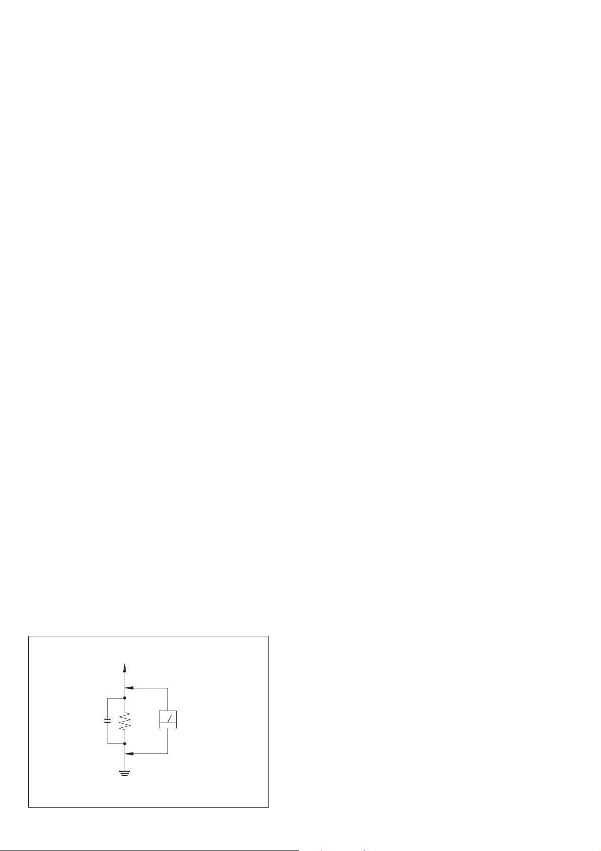
3. Measuring the voltage drop across a resistor by means of a
VOM or battery-operated A C voltmeter . The “limit” indication
is 0.75 V, so analog meters must have an accurate low-voltage
scale. The Simpson 250 and Sanwa SH-63Trd are examples of
a passive VOM that is suitable. Nearly all battery operated
digital multimeters that have a 2V AC range are suitable. (See
Fig. A)
5. ELECTRICAL PARTS LIST································ 31
T o Exposed Metal
Parts on Set
AC
0.15
µ
F
Fig. A. Using an A C v oltmeter to check A C leakage.
1.5 k
Ω
Earth Ground
Voltmeter
(0.75 V)
SAFETY-RELATED COMPONENT WARNING!!
COMPONENTS IDENTIFIED BY MARK ! OR DO TTED LINE WITH
MARK ! ON THE SCHEMATIC DIAGRAMS AND IN THE PARTS
LIST ARE CRITICAL TO SAFE OPERATION. REPLACE THESE
COMPONENTS WITH SONY PARTS WHOSE PART NUMBERS
APPEAR AS SHOWN IN THIS MANUAL OR IN SUPPLEMENTS
PUBLISHED BY SONY.
— 2 —
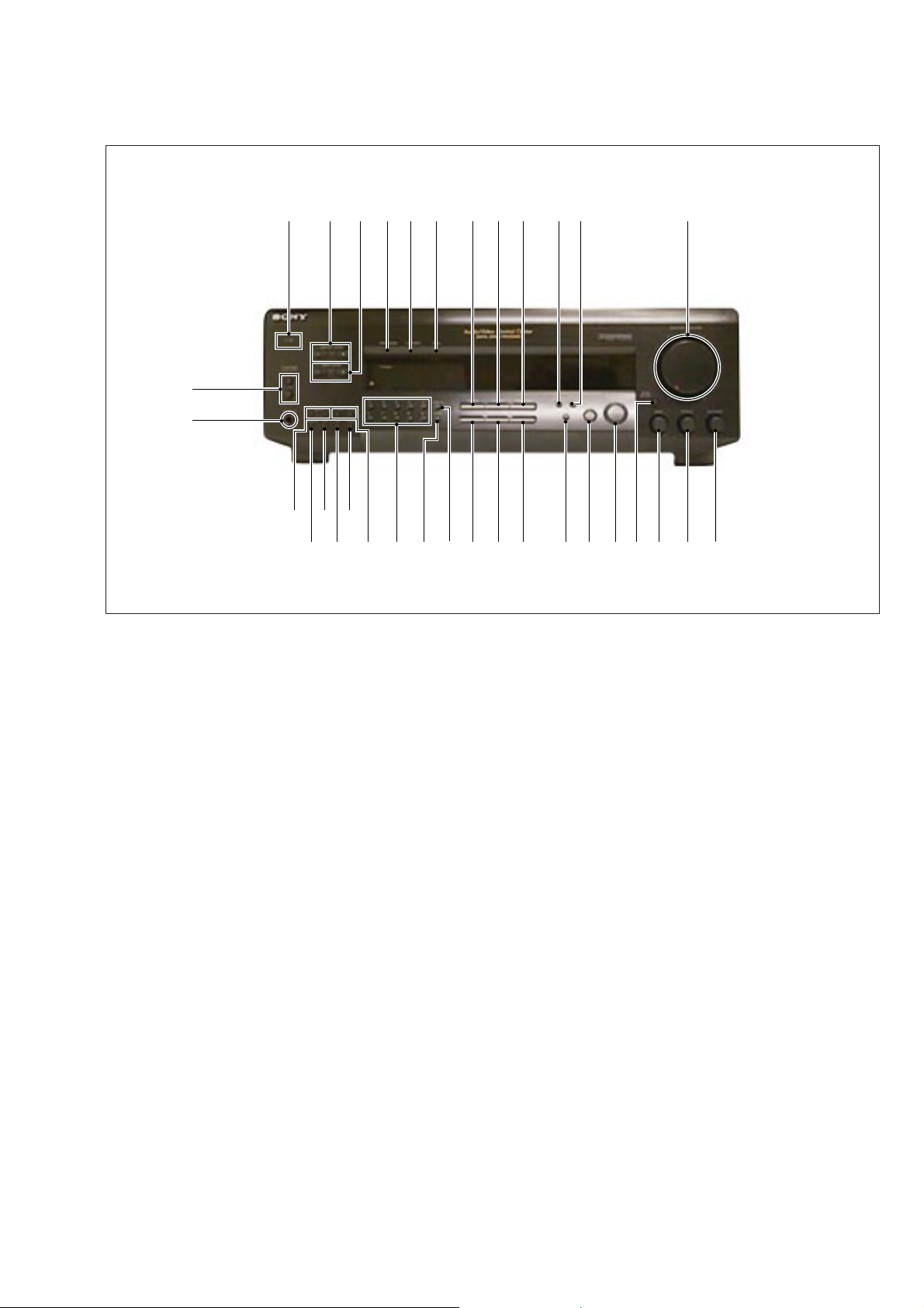
LOCATION AND FUNCTION OF CONTROLS
12#£34 5 !•!¶!§!¢!
6
[FRONT PANEL]
#™
#¡
SECTION 1
GENERAL
£
@§@•#º
1 POWER switch (I/u)
2 CENTER LEVEL +, – buttons
3 PRO LOGIC indicator
4 C. STUDIO indicator
5 HALL indicator
6 MASTER VOLUME control
7 BALANCE control
8 TREBLE control
9 BASS control
0 BASS BOOST button/indicator
!¡ SURROUND ON/OFF button
!™ MODE button
!£ SET UP button
!¢ EFECT/DELAY TIME button
!∞ 5.1/DVD INPUT button
!§ TAPE/MD FUNCTION button
!¶ TV/DBS FUNCTION button
78!¡!∞ !™@º !ª@¡@™@£@¢@∞@¶@ª 9!º
!• VIDEO FUNCTION button
!ª PHONO FUNCTION button
@º TUNER FUNCTION button
@¡ CD FUNCTION button
@™ DIRECT button
@£ SHIFT button
@¢ Numeric buttons
@∞ PRESET TUNING +, – buttons
@§ MEMORY button
@¶ AM button
@• FM button
@ª FM MODE button
#º TUNING +, – buttons
#¡ PHONES jack
#™ SPEAKERS A/B buttons
#£ REAR LEVEL +, – buttons
— 3 —
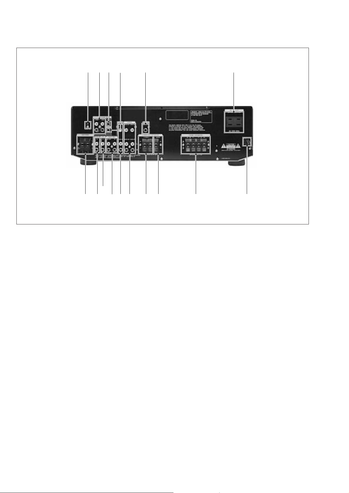
[REAR PANEL]
1 2 !¢ !∞
4567 8 9 0 !§ !¡ !£
1 SIGNAL GND
2 5.1/DVD INPUT (FRONT/REAR)
3 WOOFER
4 ANTENNA (AM/FM)
5 PHONO
6 CD
7 TAPE/MD
8 TV/DBS
3
!™
9 VIDEO
0 SURROUND SPEAKERS (REAR)
!¡ FRONT SPEAKERS
!™ AC OUTLET
!£ AC power code
!¢ 5.1/DVD INPUT (CENTER)
!∞ 5.1/DVD INPUT (WOOFER)
!§ SURROUND SPEAKERS (CENTER)
— 4 —
SECTION 2
SP-SW BOARD
PRIMARY BOARD
SECONDARY BOARD
STANDBY BOARD
MAIN BOARD
VIDEO BOARD
SWITCH BOARD
VOLUME BOARD
VR-TONE BOARD
KEY BOARD
DISPLAY BOARD
TEST MODE
SECTION 3
DIAGRAMS
INITIALIZATION MODE
* All preset contents are cleared when this mode is activated. Use
this mode before returning the product to clients upon
completion of repair.
* Procedure:
While depressing the VIDEO, TAPE/MD and the CD buttons
simultaneously , press the power [I/u] button to turn on the main
power. The message INITIAL appears and initialization is
performed.
FLUORESCENT INDICATOR TUBE TEST MODE
* All fluorescent se gments are tested. When this test is activ ated,
all segments turn on at the same time, then each segment turns
on one after another.
* Procedure:
While depressing the CD and the TAPE/MD buttons
simultaneously , press the power [I/u] button to turn on the main
power. All segments turn on at the same time, then each segment
turns on one after another . The message FINISH appears when
this test is complete.
AM CHANNEL STEP 9 kHz/10 kHz
SELECTION MODE
* Either the 9 kHz step or 10 kHz step can be selected for the AM
channel step.
* Procedure:
Set the FUNCTION to AM. Turn off the main power.
While depressing the TUNING+ button, press the power [I/u]
button to turn on the main power. Either the messa ge 9k STEP
or 10k STEP appears. Select the desired step.
REAR SPEAKER GAIN UP MODE
* The rear speaker gain can be set to either NORMAL or GAIN
UP.
* Procedure:
While depressing the -SURROUND button, press the power [I/
u] b utton to turn on the main power. Either the message
NORMAL or GAIN UP appears. When the product enters this
mode again, the other gain appears. Select the desired gain.
3-1. CIRCUIT BOARDS LOCATION
THIS NOTE IS COMMON FOR PRINTED WIRING
BOARDS AND SCHEMATIC DIAGRAMS.
(In addition to this necessary note is printed in each
block.)
For schematic diagrams.
Note:
• All capacitors are in µF unless otherwise noted. pF: µµF
50 WV or less are not indicated except for electrolytics
and tantalums.
• All resistors are in Ω and 1/
specified.
• % : indicates tolerance.
• ¢ : internal component.
• 2 : nonflammable resistor.
• 1 : fusib le resistor.
• C : panel designation.
Note: The components identified by mark ! or dotted line
with mark ! are critical for safety.
Replace only with part number specified.
• U : B+ Line.
• V : B– Line.
• Voltages and waveforms are dc with respect to ground
under no-signal (detuned) conditions.
No mark : FM
• Voltages are taken with a VOM (Input impedance 10 MΩ).
V oltage variations may be noted due to normal production
tolerances.
• Waveforms are taken with a oscilloscope.
• Circled numbers refer to waveforms.
• Signal path.
F : FM
W or less unless otherwise
4
For printed wiring boards.
Note:
• X : parts extracted from the component side.
• b : Pattern from the side which enables seeing.
• Wa veforms
1 IC300 @¢ (OSC)
8MHz
4.75Vp-p
2 IC201 #¢ (X1)
4.19MHz
5.3Vp-p
— 5 — — 6 —
STR-SE581
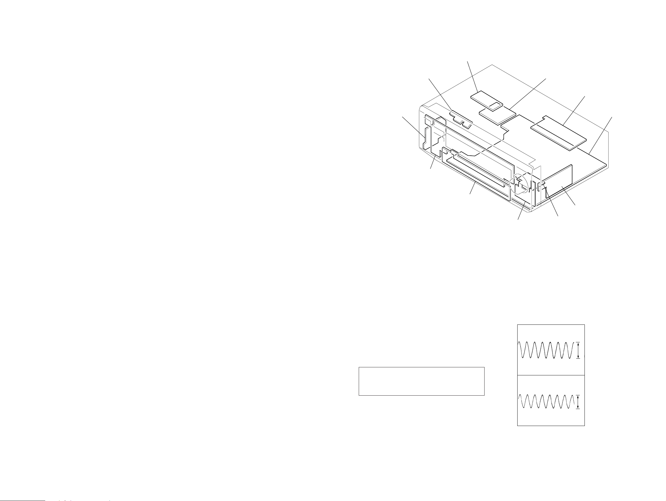
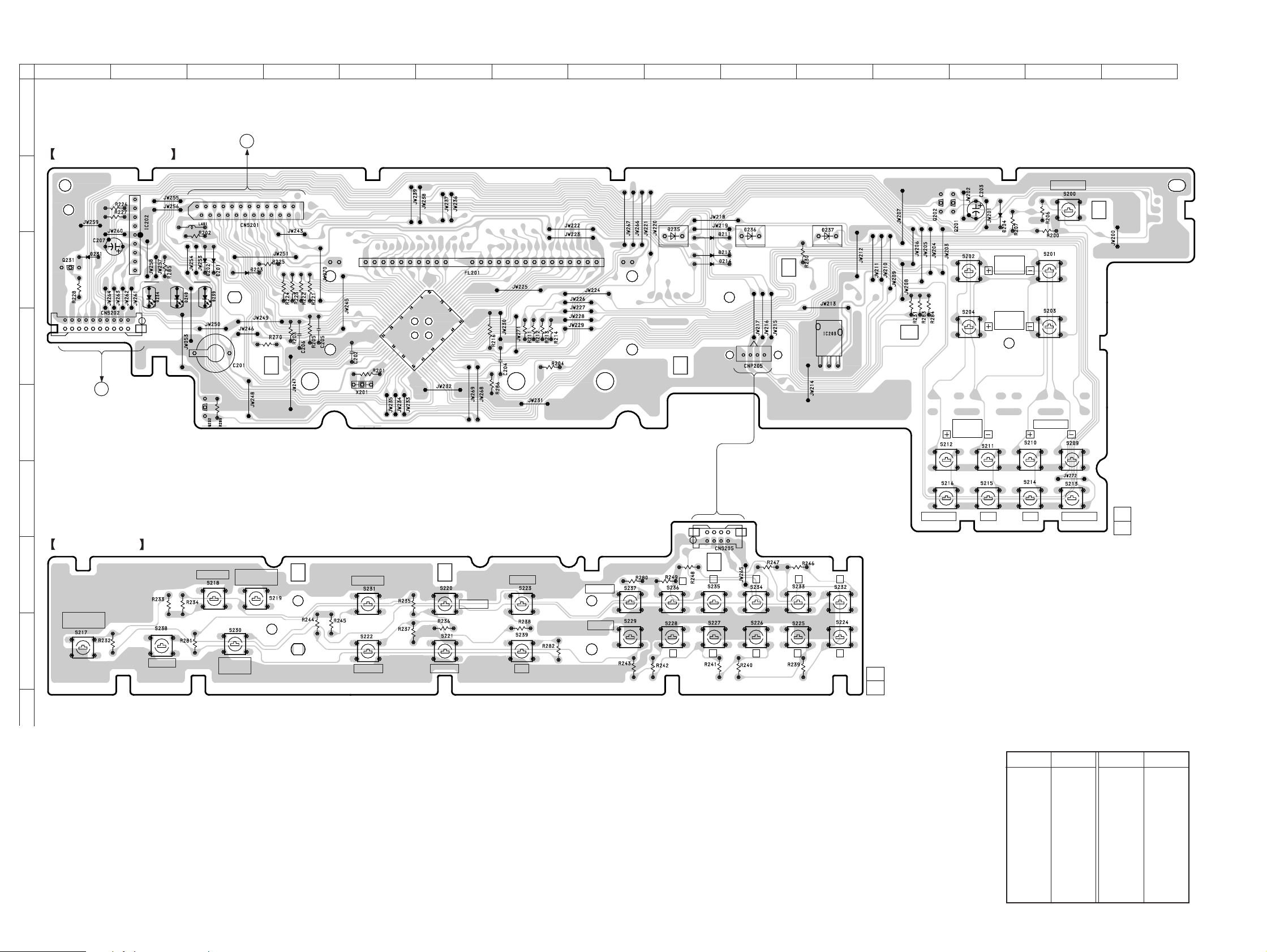
3-2. PRINTED WIRING BOARD — DISPLAY SECTION —
12
A
DISPLAY BOARD
B
E
C
10
D
E
VOLUME BOARD
CNP202
(Page 11)
TO
34567891011121314
TO
MAIN BOARD
CNS204
J
(Page 16)
1
9
1
F
(5.1 INPUT)
1
2
E
23
22
1 80
IC201
24
25
40 41
65
64
(HALL) (C.STUDIO) (PRO LOGIC)
(REMOTO SEUSOR)
1
4
EE
PRESET
TUNING
CENTER
LEVEL
REAR
LEVEL
POWER
TUNING
15
F
KEY BOARD
G
H
16
SURROUND
ON/OFF
MODE
SET UP
DELAY TIME
5.1/DVD
INPUT
EFFECT
TAPE/MD
TV/DBS
VIDEO
CDTUNERPHONO
DIRECT
SHIFT
MEMORY
1
4
5
2
1-665-281-
134
67890
11
(12)
AM
FM
FM MODE
1-665-280-
11
(12)
• Semiconductor Location
Ref. No. Location
D201 C-3 D202 C-3 D203 C-3 D204 B-13 D211 C-9 D213 C-9 D214 C-9 D231 C-1 D234 C-2 D235 C-9 D236 C-10 D237 C-11
Ref. No. Location
D239 C-3 D240 C-2
IC201 D-6
IC202 B-2
IC203 D-11
Q201 B-13 Q202 B-12 Q231 C-1 Q232 E-3
— 7 — — 8 —
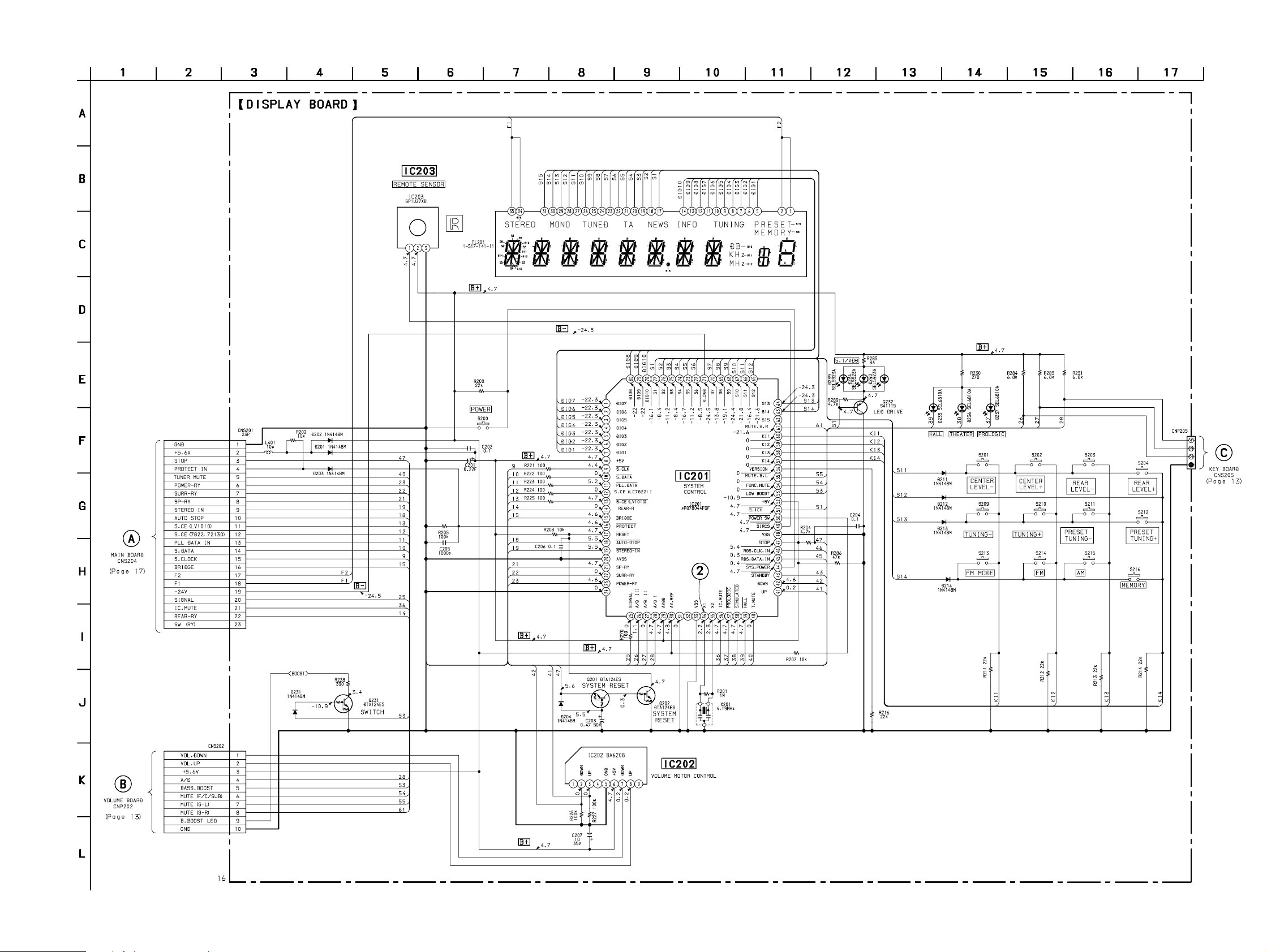
3-3. SCHEMATIC DIAGRAM — DISPLAY SECTION — • See page 6 for Waveforms. • See page 25 for IC Pin Functions.
STR-SE581
— 9 — — 10 —
STR-SE581
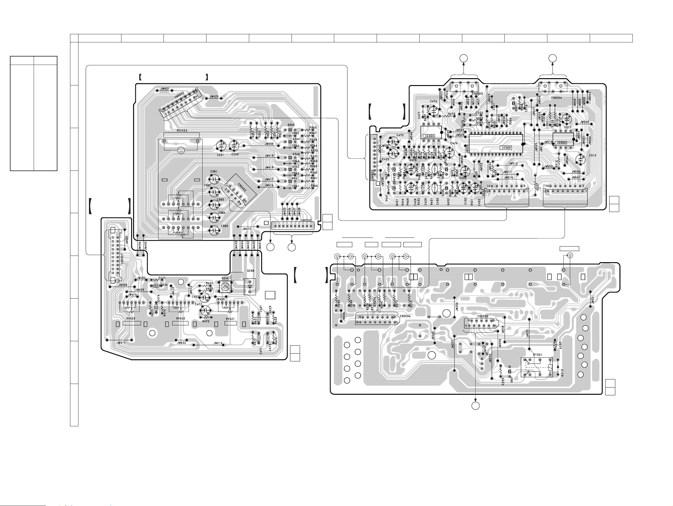
3-4. PRINTED WIRING BOARD — VOLUME/VIDEO SECTION —
• Semiconductor
Location
Ref. No. Location
D238 F-5 D310 H-12
IC404 C-9 IC500 C-11 IC502 C-12
Q361 D-6 Q362 C-6 Q363 C-6 Q364 C-6 Q365 C-6 Q367 H-11 Q401 D-8 Q402 D-9 Q451 D-8 Q452 D-9 Q501 B-11
A
B
C
D
E
F
12
VOLUME BOARD
MASTER VOLUME
VR-TONE
BOARD
10
1
345678910111213
TO
MAIN BOARD
G
CNP503
(Page 15) (Page 15)
1
7
E
1
TO
MAIN BOARD
H
CNP504
7
SWITCH
BOARD
E
E
M
BASS
BOOST
E
E
E
10
E
TO
MAIN BOARD
CNS701
(Page 15)
1-665 283-
TO
DISPLAY BOARD
F
CNS202
(Page 7)
VIDEO
BOARD
11
1
(12)
FRONT REAR WOOFER CENTER
10
E
1
E
J501
RLRLRL
5
4
8
16
1
15
E
E
30
1
5
4
8
J253
WOOFER
1
CN505CN501
1-665 255-
11
(12)
G
H
JW261
TREBLEBALANCE
16
I
BASS
1-665-284-
11
(12)
TO
MAIN BOARD
I
CNS251
(Page 15)
E
11
1-665-261-
(12)
— 11 — — 12 —
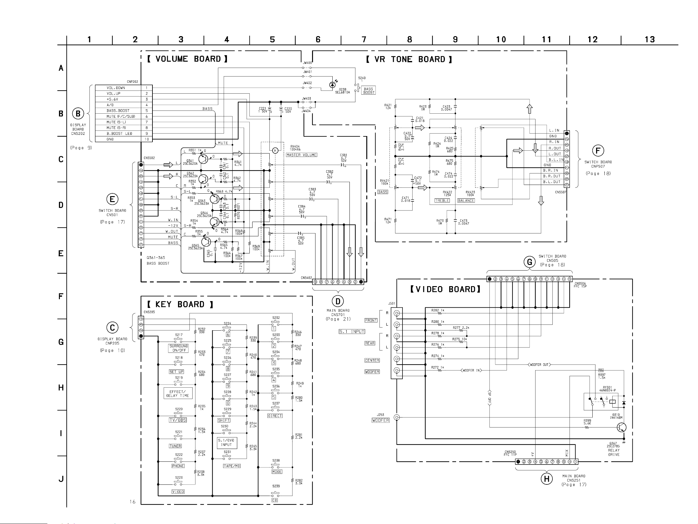
3-5. SCHEMATIC DIAGRAM — VOLUME/VIDEO SECTION — • See page 7 for KEY Board Printed Wiring Board.
STR-SE581
— 13 — — 14 —
 Loading...