

Page 1

3-798-615-22 (1)
FM Stereo
FM-AM Receiver
Operating Instructions
STR-GX900ES
STR-GX800ES
1994 by Sony Corporation
Page 2
Warning
I
WARNING
To prevent fire or shock hazard, do not expose the unit to rain or moisture.
This symbol is intended to alert the user to
the presence of uninsulated "dangerous
voltage" within the product's enclosure that
may be of sufficient magnitude to constitute
a risk of electric shock to persons.
This symbol is intended to alert the user to
the presence of important operating and
maintenance (servicing) instructions in the
literature accompanying the appliance.
Owner's Record
The model number is located on the rear exterior and serial
number is on the rear. Record the serial number in the
space provided below. Refer to these numbers whenever
you call upon your Sony dealer regarding this product.
INFORMATION
This equipment has been tested and found to comply with
the limits for a Class B digital device, pursuant to Part 15 of
the FCC Rules. These limits are designed to provide
reasonable protection against harmful interference in a
residential installation. This equipment generates, uses, and
can radiate radio frequency energy and, if not installed and
used in accordance with the instructions, may cause harmful
interference to radio communications. However, there is no
guarantee that interference will not occur in a particular
installation. If this equipment does cause harmful
interference to radio or television reception, which can be
determined by turning the equipment off and on, the user is
encouraged to try to correct the interference by one or more
of the following measures:
Reorient or relocate the receiving antenna.
Increase the separation between the equipment and
receiver.
Connect the equipment into an outlet on a circuit
different from that to which the receiver is connected.
Consult the dealer or an experienced radio/TV
technician for help.
CAUTION
You are cautioned that any changes or modifications not
expressly npprox'ed in this manual could void vour authority
to operate this equipment.
For the customers in Canada
CAUTION :
TO PREVENT ELECTRIC SHOCK, DO NOT USE THIS
POLARIZED AC PLUG WITH AN EXTENSION CORD,
RECEPTACLE OR OTHER OUTLET UNLESS THE
BLADES CAN BE FULLY INSERTED TO PREVENT
BLADE EXPOSURE.
--------------------
Model No.
Note to CATV system installer
This reminder is provided to call the CATV system
installer's attention to Article 820-40 of the NEC that
provides guidelines for proper grounding and, in
particular, specifies that the cable ground shall be
connected to the grounding system of the building, as
close to the point of cable entry as practical.
Serial No.
Page 3

Table of Contents
Introduction
Overview
Precautions
Chapter 1 Getting Started
Unpacking................................................................................5
Hookups...................................................................................6
Chapter 2 Basic Operations
Listening to/Watching a Program Source
Receiving Broadcasts............................................................16
Watching Video Programs....................................................19
Using Pre-programmed Sound Fields...................................20
.................................................................................
..............................................................................
Checking the Supplied Accessories
Inserting the Batteries into the Remote Control
Connecting an FM Antenna
Connecting an AM Antenna
Connecting Audio Components
Connecting Video Components
Connechrg Speaker Systems.............................................9
Connecting External Amplifiers
Connecting the AC Power
Selecting a Program Source
Selecting the Speaker System
Adjusting the Audio........................................................12
Using the Remote Control
Changing the Settings of the FUNCTION Buttons..........15
Direct Tuning
Automatic Tuning
Presetting Stations...........................................................17
Recei\ ing Preset Stations
Watching Video Programs..............................................19
Combining the Video Image with the
Sound from Another Program Source
..................................................................
..............................................
..............................................
............................................................
................................................
..................................
..............
..............................................
.............................................
........................................
........................................
.....................................
.............................
............................................
.........................................
..........................
10
11
12
12
12
13
16
19
4
5
5
5
6
6
7
8
17
18
Chapter 4 Digital Sound Effects
Dolby Surround Sound..........................................................30
Selecting the Center Mode
Adjusting the Speaker Volume.......................................31
Adjusting the Delay Time of the Rear Speakers
Creating Custom Sound Field
Adjustable Parameters.....................................................33
Understanding the Surround Sound Parameters for
the STR-GX900ES
Adjusting Parameters
Selecting the Sound Field Setting
Chapter 5 Other Information
Troubleshooting.....................................................................40
Specifications
Identifying the Parts and Controls
Front Panel
Remote Control
Index
Quick Reference................................................................48
........................................................................
......................................................................
...............................................................
....................................................................................
..............................................
............
...............................................
.......................................................
......................................................
...................................
........................................
30
32
33
34
36
39
42
44
44
46
47
Chapter 3 Additional Operations
Recording..............................................................................21
Recording on a Tape, DAT or an MD Recorder
Recording from Another Tape (Dubbing)......................21
Recording on a Video Tape
Adding New Sound on a Video Tape during Video
Editing
..........................................................................
Indexing the Preset Stations .................................................24
Creating an Index Name for a Preset Station..................24
Scanning the Indexed Stations
Indexing a Program Source...................................................25
Using Sleep Timer.................................................................26
Programming the Remote Control........................................27
Programming Signals for Non-Sony Components
Programming New Signals onto a Previously
Programmed Button........................................................28
Obtaining More Powerful Sound..........................................29
............................................
........................................
............
..........
21
22
22
25
27
Page 4

Overview
Welcome
Congratulations on your purchase of this Sony FM stereo/FM-AM receiver !
This manual describes two models: models STR-GX900ES and STR-GX800ES. The functions
and features of these models are the same, except where noted in this manual.
Features of this receiver include:
Dolby *Pro Logic Surround Sound Decoder
• Provides four channels of sound information (front left,
center, front right, and rear).
• Four center modes, to match your speaker configuration
(WIDE, NORMAL, PHANTOM and 3 CH (channel)
LOGIC).
• Two enhanced Dolby Pro Logic sound fields, depending
on vour sound preferences (LIVE (STR-GX900ES only) and
THEATER).
• Variable delay time (15 - 30 ms).
Digital Signal Processing (DSP)
• Automatically converts all signals to digital, which lets
you adjust the sound with virtually no degradation in
sound quality.
• Allows you to customize individual sound parameters
including effect level, room size, wall type, seat position,
and reverb time. (STR-GX900ES)
Sound Field Settings
• A variety of adjustable sound fields simulate the way
experience sound in various listening environments.
STR-GX900ES includes 10 factory preset sound field
settings (HALL, ACOUSTIC, 01%RA, CHURCH,
STADIUM, LIVE, JAZZ, DANCE, THEATER, DOLBY
SUR).
STR-GX800ES includes 6 factory preset sound field
settings (HALL, ACOUSTIC, LIVE, DANCE, THEATER,
DOLBY SUR).
Digital Synthesis FM/AM Tuning
• Allows you to precisely tune in a station.
Parametric Graphic Equalizer (STR-GX900ES)
• Lets you adjust bass, middle, treble, and slope.
30 random FM/AM Station presets
• Lets you store your favorite stations in memory for easy
recall.
Programmable Remote Control
• Remote control with "learning" capability allows you to
use a single remote control for most audio and video
operations.
9 Audio/Video Inputs
• Includes five video inputs (one on front panel).
Center Channel and Surround Amps.
• Center channel amp: 100 watts (STR-GX900ES); 90 watts
(STR-GX800ES)
• Surround channel amp: 30 watts
4/8-Ohm Impedance Switch
• Lets vou use front and center speakers with either 4 or 8
ohm impedance.
Station Index
• Lets you group preset stations by specific names.
Audio/Video Editing
• Lets you combine a video image with the sound from
another program source.
About Dolby Surround Sound
The sound tracks of many programs, including current TV
shows and movies that are on video cassette and laser disc,
use Dolby Surround Sound. This enhanced audio
soundtrack complements the action as it happens on the
screen. Surround sound uses four separate channels to
direct off-screen audio effects, on-screen dialog, left-to right
panning, and music, bringing you right into the action. In
the past, you would have to go to a movie theater to
experience all the benefits of surround sound. But now, with
the special sound decoder that is built into this receiver, you
can experience Dolby Surround Sound right in your living
room, with sound that even rivals what you would
experience in a movie house.
Independent 3-Channel Amplifier
The amplifier section is composed of independent power
circuits for all channels; front left, right and center channels,
and uses a parallel push-pull output circuit. This circuit
design allows the output impedance to be lowered, while
allowing current flow and total power dissipation to
increase. The result is better performance into low
impedance loads, and at high power output levels.
Full Bandwidth Center Channel
Because as much as 70% of a typical movie's audio "energy"
comes from the center channel, Sony has designed this
receiver-with full-bandwidth center channel amplifiers
(20 Hz - 20 kHz). This discrete amp is powered by a large
transformer and uses dedicated filter capacitors for each
channel to further ensure superior audio cjuality during
transients and peak power output periods.
Power Swap
The Power Swap feature lets you add to the receiver's total
amplification without compromising the signal integrity (if
you want to add a separate power amplifier).
Low Filter (Models for U.S.A. and Canada)
For superior performance when using a subwoofer, this
switch will eliminate signals below 100 Hz from the front
speakers. This filter will prevent phase cancellation between
the subwoofer and the front speakers.
• Manufactured under license from Dolby Laboratories Licensing
Corporation. Additiondllv licensed under one or more ot the following
patents: U.S. number 3,959,590; Canadian numbers !,l)04,o03 and 1,037,877.
"Dolbv", "Pro Logic", and the double-D symbi»I are trademarks of Dolb\'
Laboratories Licensing Corporation.
Page 5
jjji
Chapter 1 Getting Started
Precautions
On safety
• For USA and Canadian models, operate the unit only on
120 V AC, 60 Hz. For the Australian model, operate the
unit only on 240 V AC, 50 Hz.
• Should any solid object or liquid fall into the cabinet,
unplug the unit and have it checked by qualified
personnel before operating it any further.
• Unplug the unit from the wall outlet if it is not to be used
for an extended period of time. To disconnect the cord,
pull it out by grasping the plug. Never pull the cord
itself.
• One blade of the plug is wider than the other for the
purpose of safety and will fit into the power outlet only
one way. l£you are unable to insert the plug fully into the
outlet, contact your dealer.
Place the unit in a location with adequate air circulation
This will prevent internal heat build up in the unit.
Do not install the unit:
• near heat sources such as radiators or air ducts.
• in a place subject to direct sunlight, excessive dust,
mechanical vibration or shock.
Unpacking
Checking the Supplied Accessories
Check that you have received the following items.
• FM wire antenna...............................................................(1 )
• AM loop antenna...............................................................(1)
• Remote commander (RM-P341)
• AA-size Sony batteries (SUM-3 (NS))
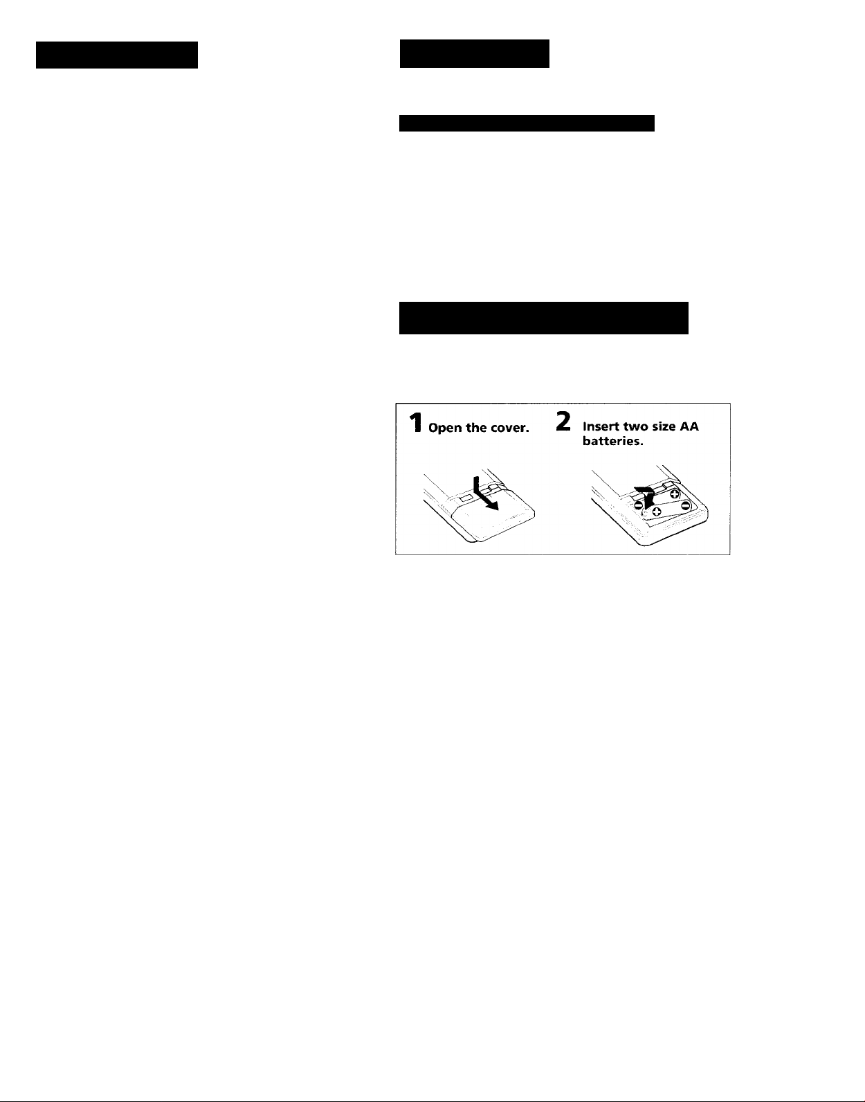
Inserting the Batteries into the Remote
Control
Insert two size AA batteries (supplied) by matching the +
and - on the batteries to the diagram inside the battery
compartment.
.......................................
..............................
(1)
(2)
Do not place anything on top of the cabinet
The top ventilation holes must be unobstructed for proper
operation of the unit and to prolong the life of its
components.
Do not throw away the carton and packing material!
Keep the packaging to transport the system for servicing, etc.
Cleaning the cabinet
Clean the cabinet, panel and controls with a soft cloth lightly
moistened with mild detergent solution. Do not use any type
of abrasive pad, scouring powder, or solvent such as alcohol
or benzine.
For customers in the U.S.A.
For detailed safety precautions, see the "IMPORTANT
SAFEGUARDS" leaflet.
If you have any question or problem concerning your unit,
please consult your nearest Sony dealer.
Notes
• If you plan not to use the remote for an extended period of
time, remove the batteries to avoid possible damage from
battery leakage.
• With a normal use, the batteries should last for
approximately six months.
• Do not mix different types of batteries.
Page 6
Hookups
This section describes how to hookup antennas, audio components, TV /VCRs, speaker
systems, and external amplifiers.
Notes
• Do not connect the power cord to an AC outlet nor press
the POWER switch before completing all other hookups.
• Be sure to fully insert the cable connectors into the jacks.
Loose connection may cause hum and noise.
• Jacks and plugs of the connecting cord are color-coded as
follows:
Red jacks and plugs: For right channel audio
White jacks and plugs: For left channel audio
Yellow jacks and plugs: For video
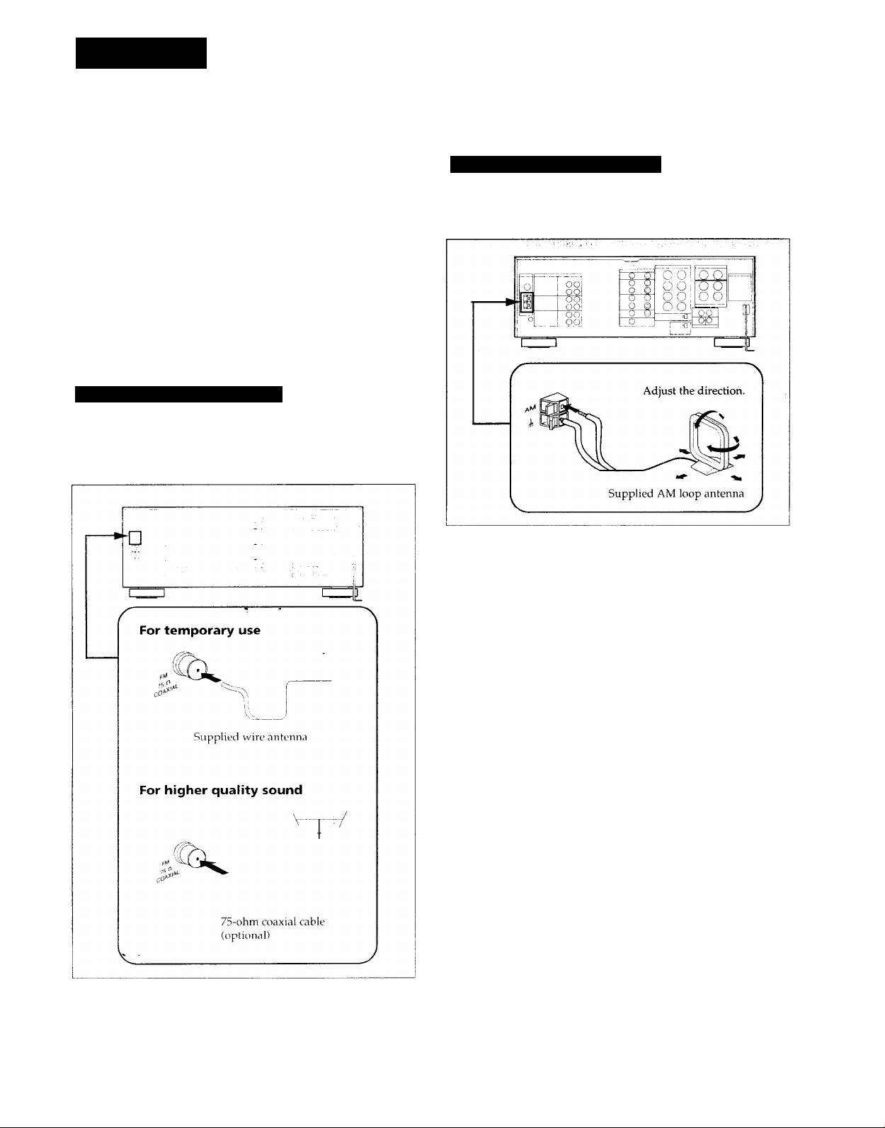
Connecting an FM Antenna
Connect the supplied FM wire antenna for temporary use.
For better sound reception, we recommend that you use a
75-ohm coaxial cable (not supplied) instead.
Connecting an AM Antenna
Connect the supplied AM loop antenna to the AM antenna
terminal, as shown below:
If you have poor AM reception
Usually, the supplied AM loop antenna ts adec]uate to
receive AM broadcasts.
If you have poor reception, connect a 20 to 50 ft. (6 to 15meter) insulated wire to the AM antenna terminal in
addition to the loop antenna. If possible, extend the wire out
of doors and keep it horizontal.
(Do not remove the AM loop antenna.)
To prevent hum
If you install an outdoor antenna, connect the ground wire to
the ANTENNA ground terminal (iJj) for lightning protection.
Page 7

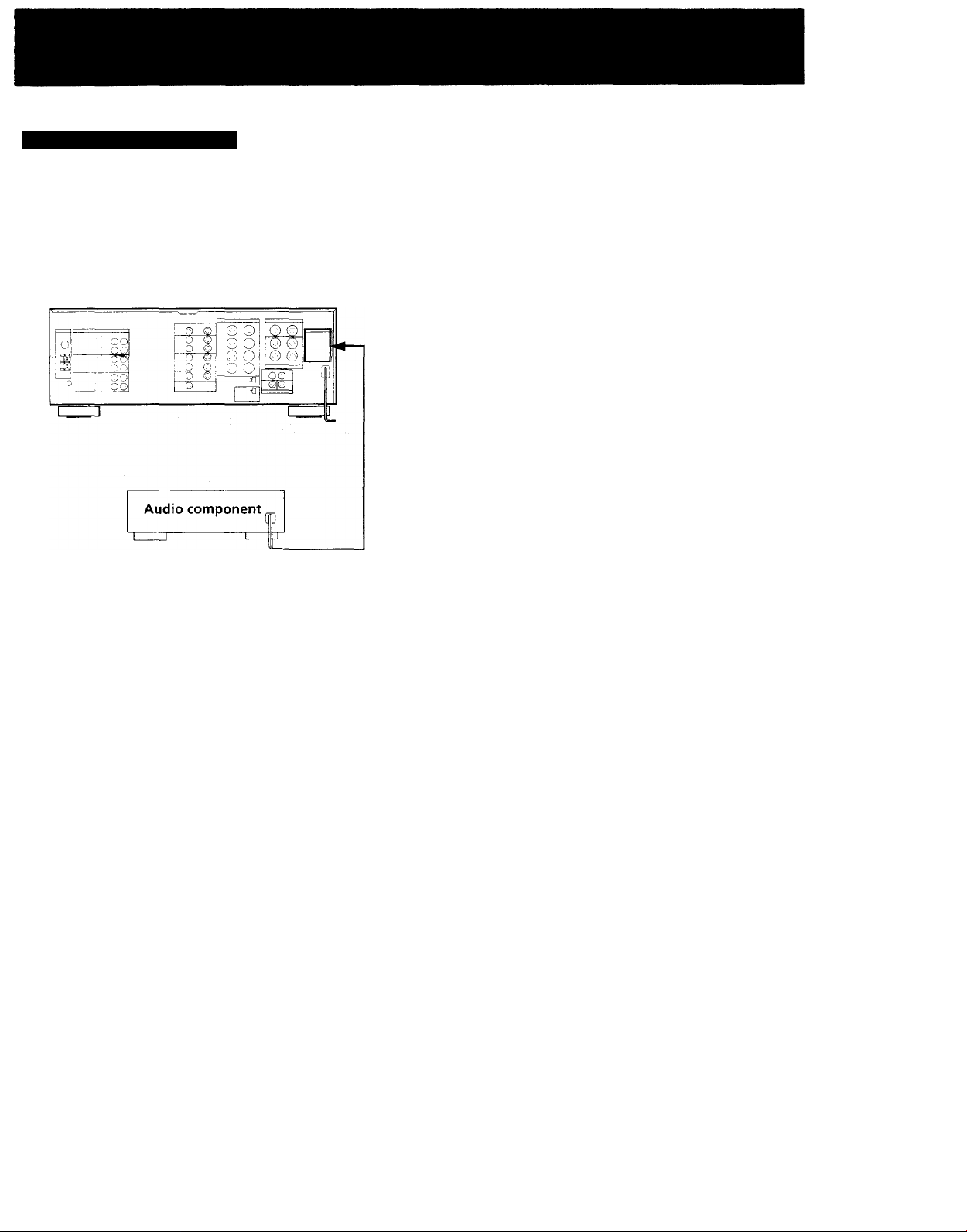
Connecting Audio Components
Make sure that you connect red plugs to the right channel (R) jacks and white plugs to the left channel (L) jacks.
to LINE IN
DAT deck or
MD recorder
to LINE OUT to LINE IN
Tape deck
mm
to LINE OUT
j'©(Q)
©©
^‘©©
©©
...A©
■c O
-©
■ ©
■ ■ ©
■ ©
— © -r Q)
... ©
Receiver
White
L .... 1 ■ CO“ '■
R O 1
Red
FRONT SPEAKERS
O o
iMPEOANCi 5€LEa
:si]
CCNTER SPEAKERS
REAR SPEAKERS
'•@©
SURROUND OUT
Other equipment
White
c L
Red
AC OUTLET
i
to OUTPUT
CD player
Turntable
to OUTPUT
Note
The TAPE IN jacks are only for monitoring the sound so that
vou cannot record the sound of a component connected to
the TAPE IN jacks. Use another IN jacks for recording.
Page 8
Hookups (continued)
Connecting Video Components
Make sure that you connect each plug correctly: red plugs to the right channel (R) jacks of audio signals; white plugs to the left
(L) channel jacks of audio signals; and yellow plugs to the video signals.
VCR 2
to AUDIO/
VIDEO OUT!
to VIDEO 3/
INPUT on the
front panel
to AUDIO/
VIDEO OUT
to AUDIO/
VIDEO IN
to AUDIO/
VIDEO OUT
LD player
s(o)@
VCR 1
to AUDIO/
VIDEO IN
mm
mm
:mm
^mm
mm
Monitor TV
to VIDEO
IN
■m'
•m
-m-
-m
to S VIDEO
OUT
Monitor TV
to S VIDEO
IN
to S VIDEO IN
VCR 1
to S VIDEO OUT
© ©:
© ©
© ©;
© ©
to S VIDEO
IN
VCR 2
to AUDIO/
VIDEO OUT
VCR 3 Camera
recorder
If your video components have S VIDEO IN/OUT
jacks
Use the S VIDEO jacks instead of the conventional video
jacks. This will give you a clearer picture.
Notes
• The S VIDEO circuitry and the VIDEO circuitry of this unit
are independent of each other. The signals input from the
S VIDEO jacks are not output to the VIDEO jacks, and the
signals input from the VIDEO jacks are not output to the S
VIDEO jacks.
Therefore, you can connect the S VIDEO jacks between
video components which have the S VIDEO jacks but you
should connect the VIDEO jacks if one of them has no S
VIDEO jacks.
• If your monitor TV does not have an S VIDEO IN jack
while other video components have the S VIDEO jacks, be
sure you do not connect them to the receiver's S VIDEO
jacks. Otherwise, no picture will be seen.
to AUDIO/VIDEO OUT
TV
to S VIDEO OUT
LD player
If you are connecting more than two video
components
Be sure to use the jacks in the different section for each
component.
For example, you cannot use both S VIDEO jacks and VIDEO
jacks in VIDEO 1 section simultaneously.
8
Page 9
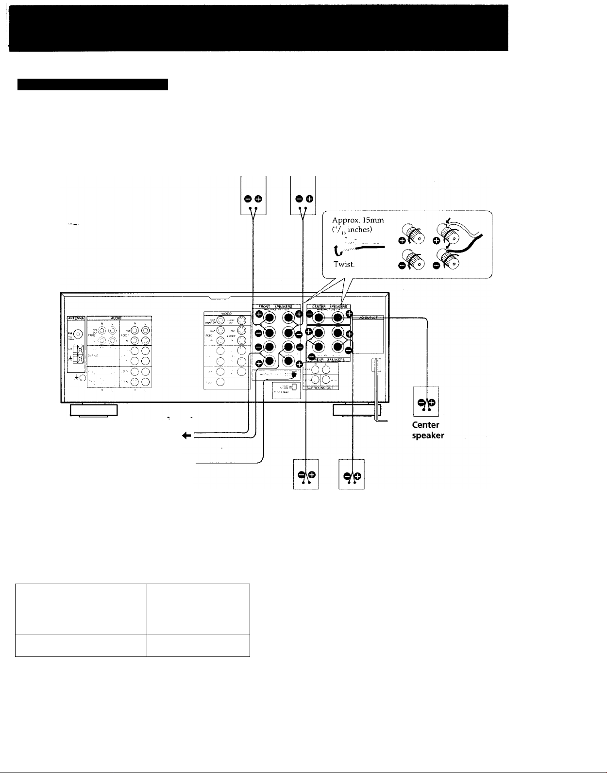
Connecting Speaker Systems
Make sure you match the + and - of the speaker cord to the +/- diagram on the speaker terminals. If the cords are reversed, the
sound will be distorted and will lack bass.
Front Front
speaker (R) speaker (L)
to the second front speaker system
IMPEDANCE
SELECT
Selecting the impedance
Select the impedance for the front and center speakers.
If nominal impedance of
your speaker is:
4 ohms or higher
8 ohms or higher
-
Set the IMPEDANCE
SELECTOR to:
4 n
Sil
If you are using both FRONT SPEAKERS A and B systems,
use the speakers having nominal impedance of more than
8 ohms and set the IMPEDANCE SELECTOR to the 4 LI
position.
Rear Rear
speaker (R) speaker (L)
Deciding where to place your speakers
To get the optimum surround sound effect, connect both
front and rear speakers. If you have a center speaker, place it
between both left and right front speakers.
Even though you do not have a full set of speakers, the
receiver is designed to give the best possible surround sound
effect. For details, see "Selecting the Center Mode" on page
.80.
Page 10
Hookups (continued)
Connecting External Amplifiers
To obtain more powerful sound, connect an external power amplifier or a pre-amplifier.
Power amplifier for
the rear speakers
ANTENNA AUD
I
■ @ (Q)
.©(§)
0
è
viOEO '
-@©
ViOEM
"©©
— ©@
”-©©
-----------
ViOEOi
VIDE02
LO"
©
©
POWER SWAP selector*-
If you are connecting a subwoofer with a power
amplifier
Connect the line input jack of the subwoofer to the
SURROUND OUT MONO jack of this receiver.
If you are connecting a subwoofer without a power
amplifier
Connect it through a monaural power amplifier.
On the low cut filter for front speakers (Models for
U.S.A. and Canada only)
When using a subwoofer, the low frequency signal should be
cut from the front speakers for better sound reproduction.
To activate the low cut filter function, turn on the power
with the POWER switch while holding down the LOW
BOOST button. The low cut filter indicator on the front
panel lights up.
To cancel tlie low cut filter function, perform this procedure
a iia i n.
___
VIDFO
SVtOEO
svceo
©•r
© ■
•(o; co;
© ..
© .
s
:© ©
■(o) (d
©
©
IMPEOANCE SELfCT
-Co) (o)G
O) ( O
REAR SPEAKERS
1
SURI OUND 3UT
Subwoofer
Monaural power
amplifier for a
center speaker
If you are connecting a power amplifier for the rear
speakers
Connect the input jacks of the power amplifier to the
SURROUND OUT REAR jacks of this receiver. Make sure
the POWER SWAP selector is set to NORMAL.
If you are connecting a monaural power amplifier
for the center speaker
Connect the input jack of the power amplifier to the
SURROUND CENTER jack of this receiver.
* To obtain more powerful sound from front and rear
speakers, you can use the POWER SWAP selector. The
total output power of your audio/video system will be
increased. See "Obtaining More Powerful Sound" on page
29.
10
Page 11
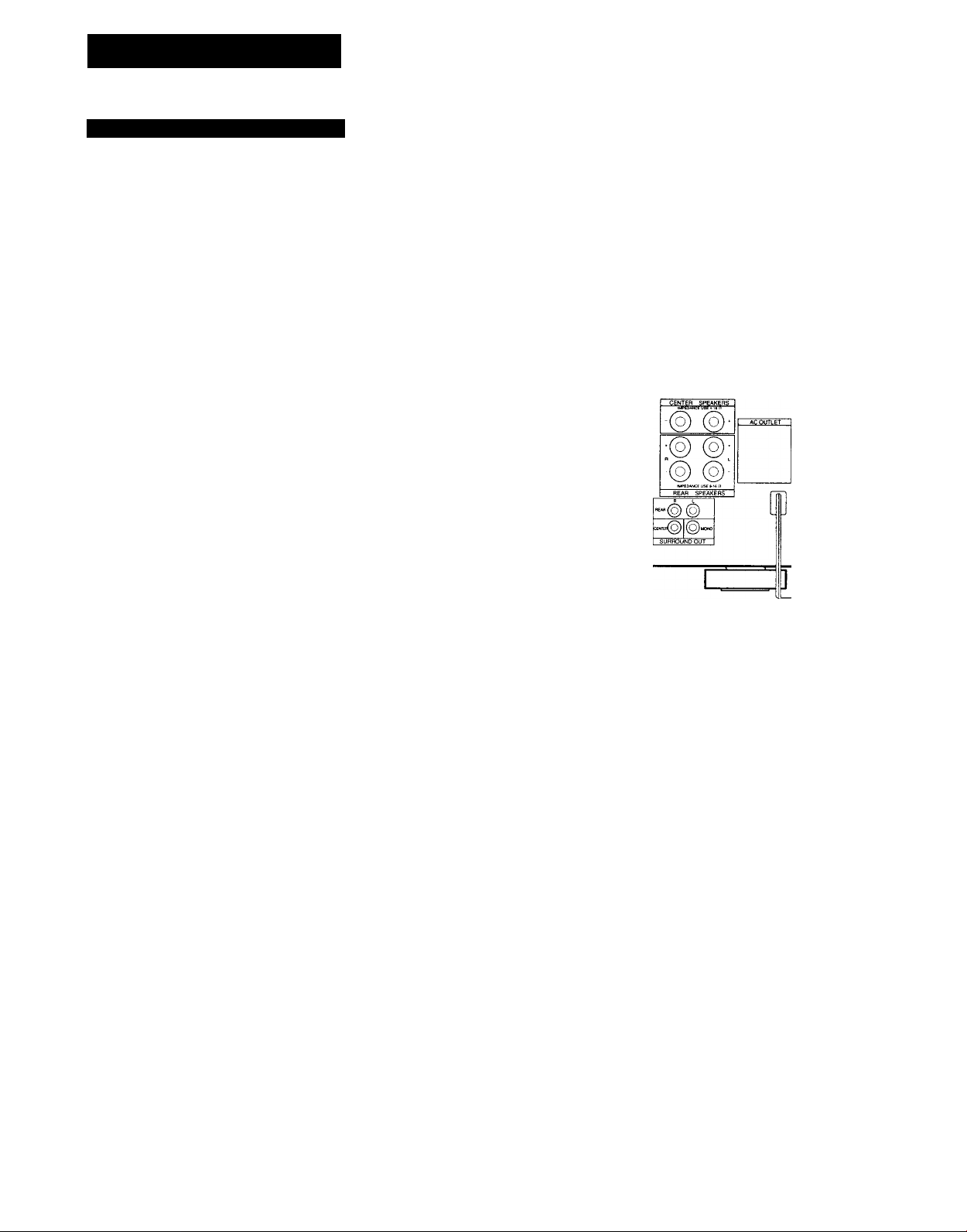
Connecting the AC Power
Connect the power cord from this receiver to a wall outlet. If
you connect other audio components to the SWITCHED AC
OUTLET on the receiver, the receiver will supply power to
the connected components only when the receiver is turned
on.
I
Caution
Be careful that the total power consumption of components
connected to the outlet(s) on the receiver does not exceed 120
watts (U.S.A. and Canada models) or 100 watts (Australia
model).
Do not connect electrical home appliances such as an electric
iron, fan, TV, or other high-wattage appliances to the
outlet(s).
11
Page 12
Listening to/Watching a Program Source
Selecting a Program Source
POWER ON
o
c , _ ; j...!..
[ ____
V'
'3
DAT or MD recorder I
Select a program source.
Rotate the FUNCTION knob until the function
indicator you want to select lights on the display.
1 1 i
1
Turntable
CD player
Tape deck
VCR
ID player
I
TAPE
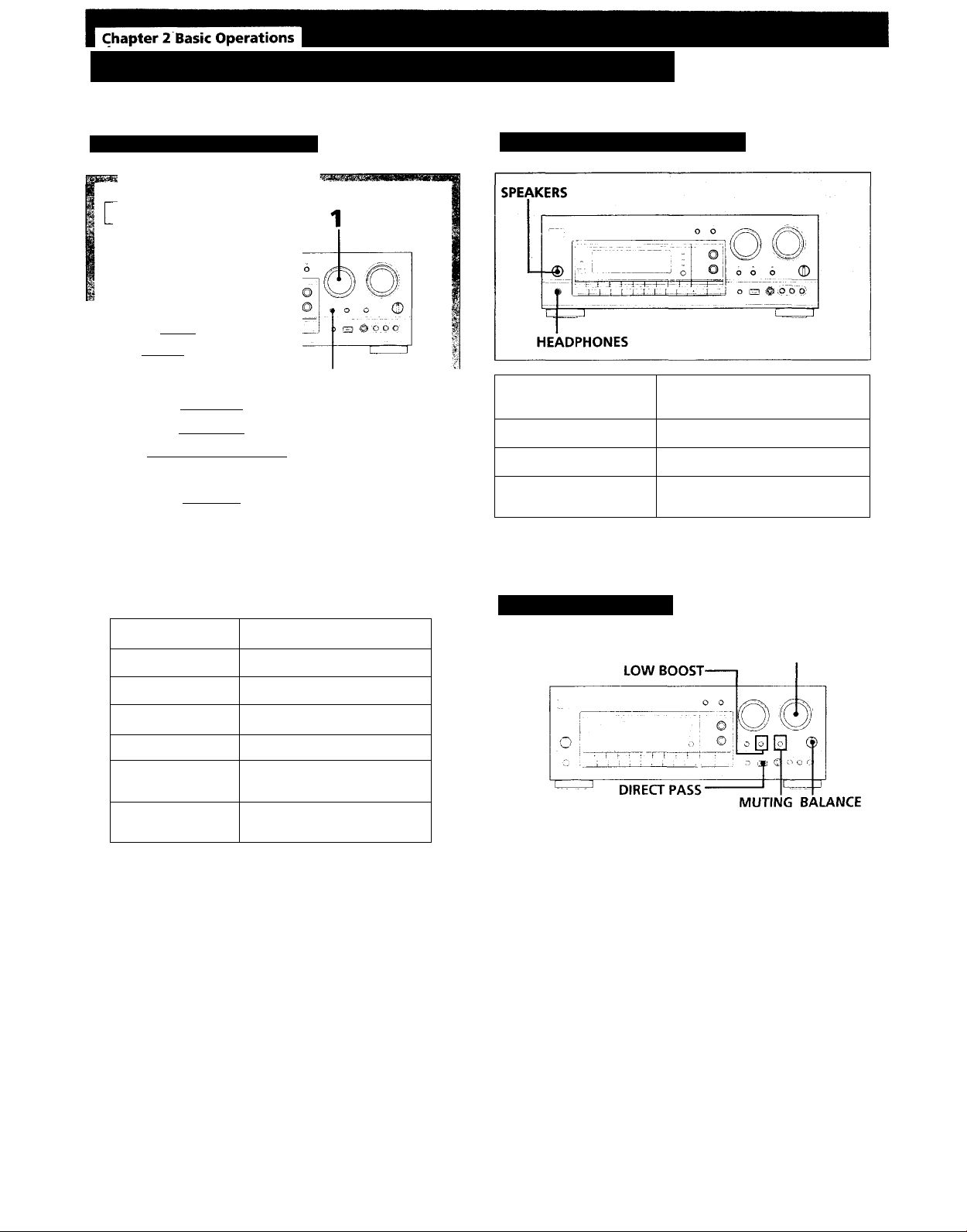
Selecting the Speaker System
If you connect and
drive
Speaker system A A
Speaker system B B
Both speaker systems A
and B
For headphone listening: Connect headphones to the
HEADPHONES jack and set SPEAKERS to OFF.
Set the SPEAKERS selector
to
A+B
Adjusting the Audio
To select
Phono record
Radio broadcast
TV broadcast
Compact disc
DAT or MD
program
Video program
For taped program: Press TAPE. The MONITOR
indicator lights.
If you select a program source using the remote, you can
turn on the power of the component as well as the
receiver.
Start playback of the selected program, for example, a CD.
Set to
PHONO TUNER
TV
CD
DAT/MD
VIDEO 1, VIDEO 2,
VIDEO 3, LD
MASTER VOLUME
To adjust volume
Turn MASTER VOLUME.
To mute the sound
Press MUTING.
The indicator lights up and the v'olume level is reduced to a
low level (- 20 dB attenuation).
Press it again to restore the previous listening level.
To adjust the balance
Adjust BALANCE to correct stereo imaging, when the stereo
image is not symmetrical.
To reinforce the bass
Press LOW BOOST so that the indicator lights up. Press it
again to turn off the effect (the indicator goes off).
(Recommended for low listening levels.)
12
To listen to the sound without sound effect
Press DIRECT PASS so that the indicator in the button lights
up.
The settings of TONE (STR-GX800ES), EQUALIZER (STRGX900ES), SOUND FIELD and LOW BOOST will have no
effect.
Page 13
Using the Remote Control
The remote lets you operate the connected components as
well as the receiver. Press one of the SYSTEM CONTROL/
FUNCTION buttons first to select the program source, then
use the following buttons to operate each component.
The SYSTEM CONTROL/FUNCTION buttons are factory
set as described in the following list.
FUNCTION button
TUNER
TAPE
DAT/MD
CD ~~
LD
VIDEO 1
VIDEO 2
VIDEO 3
TV
PHONO
Operates
Tuner
Tape deck
DAT deck/MD recorder
CD player
LD player
VCR (VTR 1 mode)
VCR (VTR 2 mode)
VCR (VTR 3 mode)
TV
(The receiver enters PHONO mode)
You can use the RMS function of Sony cassette decks with
this remote. For more information on the availability of
Sony stereo cassette decks with RMS capability, contact your
nearest S('n\' dealer.
If you use Sony TVs
• When you press the VIDEO 1,2,3 or LD button, the TV
automatically turns on and switches to appropriate VIDEO
input.
• When you press the TV button, the TV turns on and
switches to the TV reception mode. (If the TV does not
switch to the TV reception mode, hold down the button
until the TV is turned on or press the button again after the
TV is turned on.)
• If the TV input does not switch to the appropriate mode,
switch the input signal with the TV/VIDEO button.
• Some Sony TVs cannot be turned on with the remote
supplied with this unit. In this case, use the remote
supplied with the TV to turn it on.
If you use TV most of the time (Only for Sony TVs)
You can set the remote to operate only the TV. Press the TV
CONTROL ON button. This sets up the remote so that it
works only with your TV.
Turning on power of each component
SYSTEM OFF
TV CONTROL
ON
-VISUAL POWER
TV/VIDEO
Press one of the SYSTEM CONTROUFUNCTION buttons.
The receiver, the audio component connected to the
AC OUTLET of the receiver, VCR, LDP and TV are
turned on.
Press the button for the function you want to use.
The function of the buttons changes depending on
which component you are operating.
(See "Operative Buttons" on page 14.)
Turning off the power of components
• Pressing the SYSTEM OFF button turns off the power of all
components at one time.
• Pressing the VISUAL POWER button turns off only the
TV, VCRs and LD player.
• If you want to turn off the power while listening to a
program source, see "Background operation" on page 15.
13
Page 14
Listening toAA/atching a Program Source (continued)
Operative buttons
FM/AM tuner
To
Select memory pages for preset tuning
Designate preset numbers
Scan and select preset stations
Select station index names
Tape deck/DAT/MD recorder
To
Designate numbers
Designate number more than 10
(For tape deck and MD recorder)
Fastforward
Rewind
Skip selections
(For DAT and MD recorder)
Pause play
Start play
Start reverse play (For tape deck)
Select the tape running direction (For
tape decks with the RMS function)
Stop play
Clear the RMS program contents
(For tape decks with the RMS/unctipn)
Start recording (Forward direction)
Start recording
(Reverse direction for tape deck)
Program selections (For tape decks
with the RMS function)
Press
SHIFT
Numeric buttons
CH PRESET +/INDEX
Press
Numeric buttons
>10
►►
◄◄
►W (forward).
(reverse)
il
►
RMS DIRECTION
■
RMS CLEAR
RMS/START
TV/VCR/LD player
To
Designate channel numbers of
TV/VCR or selections of LD
Designate selections of LD more
than 10
Enter the selected TV/VCR channel
Select TV to see TV programs and
VIDEO to see videos
Select the output signal from the
antenna terminal on the VCR: a TV
signal or VCR program
Select a preset channel of TV or VCR CH PRESET+/Fastforward (For VCR and LD player)
Rewind (For VCR and LD player)
Pause play (For VCR and LD player)
Start play (For VCR and LD player)
Stop play (For VCR and LD player)
Skip selections (For LD player) ►►1 (forward),
Start recording (For VCR)
Turn on the power of TV, VCR,
or LD player
Press
Numeric buttons
>10
ENTER
TV/VIDEO
ANT TV/VTR
►►
II
►
■
(reverse)
VISUAL POWER
CD player
To
Designate numbers
Designate number more than 10
Skip discs
Search selections
Skip selections
Pause play
Start plav ►
Stop play
14
Press
Numeric buttons
>10
D.SKIP
►► (forward),
◄◄ (reverse)
►W (forward),
(reverse)
II
■
Page 15
Background operation
You can temporarily operate other components while
listening to/watching a program source.
1 Hold down the BACKGROUND button.
2 Hold down the numeric button* of the component you
want to operate.
3 Press the button for the operation that you want to
perform.
You can use certain buttons such as VISUAL POWER, TV/
VIDEO, CH PRESET +/-, ANT TV/ VTR, D.SKIP,
II, •.
Example: To record a CD on a tape:
—
-
----r-----:--
_l _^ _J
J J J —J
• J 'J
---
J J -J
---------------
J _) J __J
_
I __I _J
^
2 Hold down 4
1
(for a tape
1 Hold down deck).
BACKGROUND.“
I
3 Press • to
i ...J
___
_I_
—
record.
j
!
Changing the Settings of the FUNCTION Buttons
The FUNCTION buttons are preset to operate only specific
components. (The CD button operates only the CD player.)
However, if you want to use different components, you can
change the presets to control these different components.
For example, if you connect a DAT deck to the CD IN jacks,
you can operate the DAT deck with the CD FUNCTION
button by changing the preset function to the DAT function.
To change the settings of the FUNCTION buttons
1 Hold down the FUNCTION button that you want to
change.
2 Press one of the numeric (0 to 9) buttons to select a new
component.
Example: To change the CD FUNCTION button to operate
a DAT deck, press 2 (for the DAT deck) while holding down
the CD button.
1 Hold down CD.
■ 2 Press 2
(DAT).
Note
You can record only in the forward directiori with
background operation.
* For a list of the components that are assigned to the
numeric buttons, see the table in "Changing the Settings of
the FUNCTION Buttons" on this page.
Note
• The settings of the TUNER button and the PHONO button
cannot be changed.
• To change the FUNCTION buttons back to their original
preset, perform these procedures again.
With the numeric buttons (0 to 9), each function can be
selected as described in the following table:
The function to be selected
TV
CD player
DAT deck
MD recorder 3
DECK A
DECK B
LD player 6
VTR I (Remote control mode)
VTR 2 (Remote control mode)
VTR 3 (Remote control mode)
Numeric buttons
0
1
2
4
D
7
8
9
15
Page 16

Receiving Broadcasts
You can tune in a radio station directly or you can have the receiver scan all the stations until it finds the one
you want. Once you preset stations on the receiver, you do not have to tune in the station every time.
Direct Tuning
Use direct tuning if you know the frequency of the station
you want. For example, to tune in FM 102.50 MHz, press
"1", “0", "2", "5" and "0".
If you enter a frequency not covered by the tuning interval,
the entered value is automatically rounded up or down to
the closest covered value.
Tuning intervals for direct tuning are set as follows:
FM: 50 kHz interval
AM: 10 kHz interval (changeable to the 9 kHz interval)
(See page 43)
32
Rotate the FUNCTION knob to select TUNER.
The station's frequency number is displayed. If you
create a station index name (page 24), this name is
displayed instead of the frequency number.
Press FM/AM to select FM or AM.
Press DIRECT.
To change the frequency
Repeat steps 3 and 4.
If you enter a non-receivable frequency
The entered digits blink in the frequency display area, and
the station is not tuned in.
If this occurs, enter the correct frequency.
The frequency range of the receiver is as follows:
• U.S.A. and Canadian models
87.50 to 108.0 MHz for FM, and 530 to 1710 kHz (10 kHz
step) or 531 to 1710 kHz (9 kHz step) for AM
• Australian model
87.50 to 108.0 MHz for FM, and 531 to 1602 kHz (9 kHz
step) for AM
If an FM stereo program is distorted
You might want to change it to monaural. Press the FM
MODE button so that "MONO" appears on the display. You
will not have the stereo effect, but the distortion will be
reduced.
To return to the stereo mode, press the button again.
"AUTO STEREO" appears on the display.
16
Page 17

Automatic Tuning
Presetting Stations
In automatic tuning, the receiver scans all the stations to
locate the one you want. If you do not know the frequency
of the station that you want, use automatic tuning.
POWER -► ON
O I ci
O r. \
______
Rotate the FUNCTION knob to select TUNER.
The station's frequency number is displayed. If you
create a station index name (page 24), this name is
displayed instead of the frequency number.
If the index name is displayed, press
DISPLAY so that "NORMAL MODE" appears
on the display.
The frequency number is displayed.
[ ■ L - I I I
H.. i. 1 1- 1 I ..
...
....
LEVEL
2 1
. . i.. .
_______
O
o o o O
o o s 'O p O'
_
You will most likely want to preset the stations you listen to
often. The receiver can store a total of 30 FM or AM
stations. Up to 10 stations can be stored in three different
memory pages: A, B and C. (For example, a station is stored
as A7 or B3.)
Rotate the FUNCTION knob to select TUNER.
The station's frequency number is displayed. If you
create a station index name (page 24), this name is
displayed instead of the frequency number.
Tune in the station you want.
(See "Direct Tuning” on page 16 or "Automatic
Tuning" in the left column of this page.)
Press FM/AM to select FM or AM.
Press INDEX SELECTfTUNING + or - .
For a higher frequency, press TUNING +.
For a lower frequency, press TUNING -.
When a station is received, automatic tuning stops.
To receive other stations, press the button again.
If the scanning stops frequently while receiving FM
stations
Press LEVEL so that the receiver stops only at the stations
with strong signals. To cancel this (to receive stations with
weaker signals), press LEVEL until HIGH goes off.
Press MEMORY.
MEMORY is displayed.
While "MEMORY" appears, press SHIFT to
select a memory page: A, B or C.
Each time you press SHIFT, A, B or C is displayed.
While "MEMORY" appears, press the
number you want to use.
Repeat steps from 2 through 5 for presetting other
stations.
To change a preset station
Preset a new station on the number of the station to be
changed. The station will be replaced.
IMPORTANT
If the power cord is disconnected for more than one month,
the preset stations will disappear from the receiver's
memory, and you will have to preset the stations again.
17
Page 18

Receiving Broadcasts (Continued)
Receiving Preset Stations
You can tune in a preset station either by entering the preset
station number or by scanning the preset stations.
By entering preset numbers
POWER -► ON
©
0
Rotate the FUNCTION knob to select TUNER.
The station's frequency number is displayed. If you
create a station index name (page 24), this name is
displayed instead of the frequency number.
--------
2 1
?
’ o
6 6 (u)
By scanning preset stations
POWER ON
o
-'h -t-'-h-br-l—I -r4 -+-'
i I r- I t I—: I .
Rotate the FUNCTION knob to select TUNER.
The station's frequency number is displayed. If you
create a station index name (page 24), this name is
displayed instead of the frequency number.
If the index name is displayed, press
DISPLAY so that "NORMAL MODE" appears
on the display.
The frequency number is displayed.
2 1
I
o o o (0
o H ®'p"q b'
' r ~ r
If the index name is displayed, press
DISPLAY so that "NORMAL MODE" appears
on the display.
The frequency number is displayed.
Press SHIFT to select a memory page: A, B,
or C.
Each time you press SHIFT, A, B or C is displayed.
Press the numeric button of the preset
station you want.
Press PRESET TUNING + or - to select the
preset station you want.
For a higher preset number, press
PRESET TUNING +.
For a lower preset number, press
PRESET TUNING -.
A1
AO B1
+
+
CO
+
+
Cl
BO
+
+
18
Page 19

Watching Vídeo Programs
Watching Video Programs
When you watch video programs on your TV, VCR or LD
player, we recommend that you play the audio portion of the
video through the receiver (instead of your TV's speakers),
so that you can take advantage of sound field programs,
including Dolby surround sound. In this case, set the
speaker volume of TV to the minimum level.
To watch TV programs, turn on both TV and the receiver
and select TV with the FUNCTION knob on the receiver. To
watch videos or laser discs, use the following procedure if
you've hooked up your components as described in
"Connecting Video Components" on page 8. See your TV,
VCR, LD player's instruction manual if you need help.
Combining a Video Image with the Sound
from Another Program Source
You can combine a video image with sound from another
program source (including video sources).
For example, you can watch a video taped program (without
original sound) while listening a to CD.
Rotate the FUNCTION knob or press TAPE to
select the audio you want.
If you use a Sony TV
The TV turns on automatically when you press one of the
SYSTEM CONTROL/FUNCTION buttons on the remote.
Moreover, vou can use convenient functions of the remote to
watch a \ ideo program source on a Sony TV. See page 13.
Press FUNCTION MODE.
The selected audio is fixed and "VISUAL MODE"
appears on the display. In this mode, you can
select only the video source without its original
sound.
Rotate the FUNCTION knob to select the
video you want.
If you want to change the audio selected in step 1,
press FUNCTION MODE. "AUDIO MODE"
appears on the display. In this mode, you can
select any audio of the sources (including video
sources).
Play back both program sources you
selected.
Note on the FUNCTION MODE button
If you do not select the video or audio within 8 seconds after
pressing the FUNCTION MODE button, the VISUAL MODE
or AUDIO MODE is canceled and vou cannot fix the video
or audio. In this case, press the FUNCTION MODE button
until the mode that vou want appears on the display. Each
time you press the button, the mode changes as follows:
visUAL MODE ^ AUDIO MODE ^ off.
19
Page 20

Using Pre-programmed Sound Fields
This receiver comes with 10 (STR-GX900ES) or 6 (STR-GX800ES) pre-programmed sound fields.
You can use these sound fields to simulate the sound you would experience in various listening
environments. In addition to these pre-programmed sound fields, you can also create custom
sound custom fields. For creating custom sound fields, see pages 30 - 39.
Press SOUND FIELD ON/OFF to ON.
The previously selected sound field setting appears
on the display.
Press SOUND FIELD MODE until the sound
field indicator that you want lights up on
the display.
Try out different fields using the following table as a
reference. Note that some fields are designed
specifically for video programs.
SOUND FIELD
DOLBY SUR
o
Ul
THEATER
O
>
LIVE
HALL
DANCE
JAZZ (STR-
GX900ES only)
o
OPERA (STR-
Q
GX900ES only)
3
<
CHURCH (STRGX900ES only)
STADIUM (STRGX900ES only)
ACOUSTIC
Applications
For Dolby surround encoded video
programs
For movie programs on video tapes
or laser discs
For music programs on video tapes
or laser discs
For orchestral music, chamber music
or an instrumental solo
For dance music
For jazz
For operas or musicals
For church music or pipe organ
music
For a live concert in an open-air
stadium
The surround effect is defeated and
only the equalizer effect can be
obtained.
20
Page 21

l^hapteT^A^WWona^^
Recording
This receiver makes audio/video recording and editing easier. Before you get started,
make sure all the AV components are connected properly.
Recording on a Tape, DAT or an MD Recorder
You can record and make copies of audio program sources
on a tape, DAT or MD using the receiver. See your tape
deck, DAT deck or MD recorder's instruction manual if you
need help.
•=0 Audio signal flow
Recording from Another Tape (Dubbing)
Tape dubbing is possible only in the directions that are
shown below. Be sure to connect a playback deck to the
DAT/MD IN jacks and a recording deck to the TAPE REC
OUT jacks.
■=> Audio signal flow
Rotate the FUNCTION knob to select the
recording source.
Set the recording source to be ready for
playback.
For example, tune in the desired station for an EM/
AM broadcast.
3 Insert a blank tape into the recording deck or
a disc into the MD recorder and adjust the
recording level, if necessary.
4 Start recording on the recording component
and then start playing the recording source.
You can monitor the sound being recorded on a
tape
If you record on a 3-head tape deck connected to the TAPE
REC OUT jacks, you can monitor the recording results by
connecting it also to the the TAPE IN jacks. Press TAPE
while recording or dubbing, until the TAPE MONITOR
indicator lights up. To listen to the source sound, press the
button again until the indicator goes off.
Rotate the FUNCTION knob or press TAPE to
select the deck for playback.
Insert the tape you want to record into the
playback deck.
Insert a blank tape into the recording deck.
Adjust the recording level, if necessary.
Start playback on the playback deck. Then
start recording on the recording deck.
Dubbing will start.
21
Page 22

Recording (Continued)
Recording on a Video Tape
You can record and make copies of programs from other
VCR, LD player or TV using the receiver. See your VCR, LD
player or TV's instruction manual if you need help.
Signal flow
3,4
Adding New Sound on a Video Tape during Video Editing
You can record audio from all program sources while
recording video, LD or TV programs on a video tape instead
of their original sound. See your VCR, LD player or TV's
instruction manual if you need help.
Rotate the FUNCTION knob to sélect the
recording source.
^ Set the recording source to be ready for
playback.
For example, insert a source tape you want to record
from into the playback VCR.
3 Insert a blank video tape into the recording
VCR.
4 Start recording on the recording VCR and
then start playing the recording source.
Rotate the FUNCTION knob to select the
program source that contains the sound
you want.
Press FUNCTION MODE.
The selected audio is fixed and "VISUAL MODE"
appears on the display. In this mode, you can select
only the video source without its original sound.
Rotate the FUNCTION knob to select the
video you want.
If you want to change the audio selected in step 1,
press FUNCTION MODE. "AUDIO MODE"
appears on the display. In this mode, you can select
any audio of the program sources (including video
sources).
Set the recording source for audio to be
ready for playback.
22
Page 23

5 Set the video recording source to be ready
for playback.
6 Insert a blank video tape into the recording
VCR.
7 Start recording on the recording VCR and
then start playing the both video and audio
recording source.
Note on the FUNCTION MODE button
If you do not select the video or audio within 8 seconds after
pressing the FUNCTION MODE button, the VISUAL MODE
or AUDIO MODE is canceled and you cannot fix the video
or audio. In this case, press the FUNCTION MODE button
until the mode that you want appears on the display. Each
time vou press the button, the mode changes as follows:
VISUAL MODE ^ AUDIO MODE ^ off.
To record other audio on a desired part of video
1 Plav back the video recording source and press the pause
button on it at the point where vou want to record other
audio.
2 Press FUNCTION MODE twice and select the audio with
the FUNCTION knob or TAPE button.
3 Start recording on the recording VCR, release the pause
mode and start playing the recording source for audio.
23
Page 24

Indexing Preset Stations
You might find that too many preset stations make it hard to find the one you want to listen to.
This receiver includes a feature that lets you group preset stations and give each group a name
(station index). For example, you can group all the Jazz stations and label them "JAZZ." The
next time you select "JAZZ," you can scan all the stations labeled "JAZZ."
Creating an Index Name for a Preset Station
Create an index name.
You can create an index name (station index) using up to five
letters and symbols each.
POWER -► ON
o
b -4:-f-4’-+-|r-'-(—i—
©
3 4 1
O O O CD
o 3 ^ ;p o p)
To select a character, rotate the PARAMETER/EQ
LEVEL/CHARACTER knob*.
To change the position within the name, rotate the
LEVEL/FREQUENCY/POSITION knob**.
When using the remote, press A or V to select a
character. To change the position, press < or >.
If you make a mistake, move to the character
position to be corrected and enter a new character.
To use the same index name again, select the name
you have stored before by rotating the
PARAMETER/EQ LEVEL/CHARACTER knob*.
Repeat steps 2 through 4 for all other
stations to which you want to assign an
index name.
Rotate the FUNCTION knob to select
TUNER.
The station’s freejuency number is displayed. If
you have already created a station index name,
this name may be displayed instead of the
frequency number.
Tune in the preset station that you want
to create a station index name for.
To receive the preset station, see page 18.
3 Press DPC MODE until the INDEX indicator
lights up.
If you store an already categorized station under
any other index name
Only the last selected category will be stored. Each station
can be stored under only one index name.
Usable letters and symbols
You can use any of the following characters to create a
station index name:
STR-GX900ES--------------------------------------------------(space),!, •», # %, &, (,), *, +, -,., /, 0,1, 2, 3, 4, 5, 6, 7,
8, 9,:,;, <, =, >, ?, T, A, B, C, D, E, F, G, H, 1, J, K, L, M, N,
O, P, Q, R, S, T, U, V, W, X, Y, Z, [, \, ], 11, a, b, c, d, e, f,
g, h, i, j, k, 1, m, n, o, p, q, r, s, t, u, v, w, x, y, z
- STR-GX800ES
A, B, C, D, E, F, G, H, 1, J, K, L, M, N, O, P, Q, R, S, T, U, V,
W, X, Y, Z, 1, 2, 3, 4, -, (space)
* For STR-GX800ES, the name of the knob is PARAMETER/
TONE LEVEL/CHARACTER.
**For STR-GX800ES, the name of the knob is LEVEL/BASS/
TREBLE/POSITION.
----------------------------------------------------
24
Page 25

Indexing a Program Source
Scanning the Indexed Stations
You can easily find the station you want by scanning the
indexed stations.
Rotate the FUNCTION knob to select TUNER.
The station index name you created appears on the
display. The frequency number appears if you have
not created the station index name on that station.
In addition to indexing preset radio stations (see page 23),
you can also create a name (index name) for program
sources (e.g., CD, TAPE, etc.). For example, if you connected
a second tape deck to the DAT/MD jacks, you will most
likely want to display "TAPE 2" (instead of "DAT/MD")
when you use the second tape deck. The name you create
appears in the display whenever you select that program
source. You can use up to 11 letters and symbols for each
index name.
Press DISPLAY until "INDEX MODE" appears
on the display.
Each time you press this button, frequency and
station index name (if you have created one)
alternately appears on the display.
If you have not stored an index name, "
appears.
Select the station you want.
• To select a station in the same index;
Press PRESET TUNING + for a higher channel
index station and press PRESET TUNING - for a
lower channel index station.
• To select an index station other than the displayed
index station:
Press INDEX SELECT/TUNING + or - once.
Then press PRESET TUNING + for a higher
channel index station and press
PRESET TUNING - for a lower channel index
station.
_______
"
Rotate the FUNCTION knob to select a program source that you want to create an index name for.
Press DPC MODE until the INDEX indicator lights up.
Create an index name.
To select a character, rotate the PARAMETER/EQ
LEVEL/CHARACTER knob*.
To change the position within the name, rotate the
LEVEL/FREQUENCY/POSITION knob**.
Repeat steps 1 to 3 for all other program
sources you want to assign an index name
to.
* For STR-GX800ES, the name of the knob is PARAMETER/
TONE LEVEL/CHARACTER.
** For STR-GX800ES, the name of the knob is LEVEL/BASS/
TREBLE/POSITION.
25
Page 26

Indexing a Program
Source (continued)
To change the index name
Store a new name to replace it.
Usable letters and symbols
You can use any of the following characters to create a
function index name:
STR-GX900ES
(space),!, %, &,(,), % +, - /, 0,1, 2, 3,4,5, 6, 7,
8, 9,<, =, >, ?, A, B, C, D, E, F, G, H, 1, ], K, L, M, N,
O, P, Q, R, S, T, U, V, W, X, Y, Z, [, \, ], II, *, a, b, c, d, e, f,
g, h, i, j, k, 1, m, n, o, p, q, r, s, t, u, v, w, x, y, z
- STR-GX800ES----------------------------------------------------A, B, Gr D, E, F, G, H, I, J, K, L, M, N, O, P, Q, R, S, T, U, V,
W, X, Y, Z, 1, 2, 3, 4, 5, 6, 7, 8, 9,- (space)
---------------------------------------------
Using the Sleep Timer
You can set the receiver to turn off automatically at a time
that you specify.
Press SLEEP on the remote while the power is on.
Each time vou press SLEEl’, the time is displayed in
the following order;
2 hours —► 1 hour and 30 minutes —► 1 hour —*• 30
minutes —► SLEEP OFF.
Press A or V to precisely specify the sleep
time, if necessary.
You can change the sleep time by 1 minute and
extend the time up to 5 hours.
To check the remaining time of the sleep timer
Press SLEEP. The remaining time is displayed.
Note
After you have checked the remaining time, the display
returns to the function display and becomes dim.
26
Page 27

Programming the Remote Control
This remote can operate other components that are connected to the receiver. In
addition, the remote can literally "learn" the signals from non-Sony components and let
you control them.
Programming Signals for Non-Sony Components
Program a signal.
Once this remote learns the signals of the other components,
you can use other non-Sony components as part of your
system. Also if any of your other Sony components fail to
operate with this remote, use this programming function.
Your remote can "learn" only the signals from remotes that
are infrared-wireless remotes. Before you program signals,
make sure that the two remotes:
• face straight each other (as shown in step 3 below)
• are placed at a distance of approximately 2 inches (5 cm)
• are not moved during programming
LEARN indicator
2, 5
Press the FUNCTION button of the
component to be programmed.
For example, if you want to program a CD player's
remote control, press CD.
On this receiver’s remote, press the button that is to
"learn" the signal from the other remote until the
LEARN indicator blinks slowly.
Other remote
Programmable area
(operative buttons)
On the other remote, hold down the button you
want the receiver's remote to "learn."
@ Remove your finger(s) from the button(s) after the
. LEARN indicator on this remote lights up.
Note
You can program only specific buttons for specific
components. See "Operative Buttons" on page 14 for a
list of the buttons that can be programmed for each
component type. If you press a button that cannot be
programmed in step ®, the LEARN indicator blinks
rapidly.
Press the LEARN button with a ball-point pen, etc., so that the indicator lights up.
Repeat step 3 for other buttons that you
want to program.
Press the LEARN button with a ball-point pen, etc.
The LEARN indicator lights for a few seconds.
After the indicator goes off, you can control other
components with the programmed buttons.
Note
If you do not perform the next operation in about one
minute after steps 2 and 3-®, the learning mode will be
canceled. If this happens, start again at step 1.
27
Page 28

Programirimg the Remote Control
After programming
Be sure to test that the component really works with the
programmed signals.
How many signals can you store in memory?
You can store approximately 60 signals, depending on the
format of the signal being used.
Memory capacity
If the LEARN indicator does not blink or light in step 3-(i) or
(D, this indicates that the memory capacity is full. In this
case, clear the signal stored in that button following the
procedure described in "To clear a programmed signal" and
program again from the beginning. When programming,
avoid the following conditions.
• Placing the remotes too far apart from each other.
• Exposing the remotes to intense light such as of invertor
fluorescent lamp.
• Receiving infrared signals of another appliance's remote.
Notes on programming
• Remote control signals of components of manufacturers
other than Sony can be programmed only when they are
compatible with the infrared wireless remote control
system. Since the programmable remote can "learn" only
the signals output from another remote, it cannot control
components that do not use a remote.
• Do not attempt to use the programmable remote with an
air conditioner or other household appliance.
• Note that there are some special remote control signals
that cannot be programmed.
• The SYSTEM CONTROL/FUNCTION button of this
remote does not work for thex)ther components even if
their signals are programmed.
Programming a New Signal onto a Previously Programmed Button
Follow the programming procedure described on page 27.
The previously programmed signal is cleared and replaced
by the new signal.
To clear a programmed signal
1 Press the LEARN button with a bail-point pen, etc., so that
the LEARN indicator lights up.
2 Press the button to be cleared while pressing the
BACKGROUND button until the LEARN indicator goes
off.
To program a signal onto the • button for
recording
It is not possible to operate any component with only the #
button. You have to program the record standby signal and
record start signal under the 0 + ► button on the receiver's
remote. With a tape deck, you can also program the signal
under the • + button (in the reverse direction).
Notes on batteries
If the LEARN indicator does not light when a button is
pressed, this means that the batteries are low.
When the batteries are low, the remote can no longer operate
the unit and programming becomes impossible.
If this happens, replace both batteries with new ones. We
recommend you use alkaline batteries for extended use.
28
Page 29

Obtaining More Powerful Sound
If you would like to create an even more powerful system, you can expand the total
power output by using the Power Swap Function and connecting the two additional
amplifiers. Connect the speakers and additional amplifiers as shown in the diagram
below.
1 Unplug the power cord.
2 Connect the rear speakers to the FRONT
SPEAKERS terminals of this receiver.
The rear signals are output from the FRONT SPEAKERS
terminals.
3 Connect the first amplifier to the SURROUND
OUT REAR, and connect the front speakers to
this amplifier.
The front signals are output from the SURROUND OUT
REAR terminals.
4 Connect the second amplifier to the SURROUND
OUT CENTER, and connect the center speaker to
this amplifier.
The center signal is output from the SURROUND OUT
CENTER terminal.
5 Remove the cover of the POWER SWAP selector
and set the selector to the SWAP position.
After you have completed the setting, attach the cover to
the selector and plug in the power cord.
Adjusting the volume
Set the volume control of separate amplifiers to the
maximum position and adjust the volume level with the
volume control of the receiver.
Notes
• Eor best results, we recommend using a pair of equivalent
amplifiers to boost front and center speaker output. You
can, however, connect the center speakers to the CENTER
SPEAKERS terminals if you only have one additional
amplifier.
• Do not use the terminals labeled CENTER SPEAKERS or
REAR SPEAKERS if you connect two additional
amplifiers. Make connections as shown in the diagram
above.
• If you want to turn off the power swap function, set the
POWER SWAP selector to the NORMAL position.
29
Page 30

Chapter 4 Digital Sound Effects
r
Dolby Surround Sound
Many video tapes and laser discs available today are encoded with Dolby surround sound, which adds
theater-like sound to your viewing experience. To take advantage of Dolby surround sound, first select
the pre-programmed Dolby Surround sound field. To make the most out of the Dolby surround sound,
however, we recommend that you select the center mode and adjust the speaker volume based on your
speaker configuration. Also, if you have rear speakers, you can adjust the timing of the sound that comes
from the rear speakers (delay time).
Selecting the Center Mode
Since all speakers are different, the receiver offers you four
types of speaker configurations (Phantom, 3 Ch Logic,
Normal, Wide). To best fit your speaker system, you can
change how the sound comes from each speaker by selecting
one of-these four configurations. Once you make the
adjustments, you do not have to adjust them again unless
you change your speaker system.
Each time you press the CENTER MODE button, the
CENTER MODE is changed in the following order:
■ PHANTOM ■> 3 CH LCX31C -> NORMAL ■> WIDE
If you do not have a center speaker
Select PHANTOM mode.
The sound of the center channel is output from the front
speakers.
Front speaker (L)
Front speaker(R)
□
If you have a small center speaker
Select NORMAL mode.
The bass sound of the center channel is output from the
front speakers, because a small speaker cannot produce
enough bass.
If you have a medium to large center speaker
* Select WIDE mode.
This is the best possible combination of the speakers.
Rear speaker(L) Rear speaker(R)
If you have only front speakers and a center
speaker
^ Select 3 CH (Channel) LOGIC mode.
The sound of the rear channel is output from the front
speakers.
30
Note
The Dolby Pro Logic Surround Decoder is a system to
decode the software carrying the Imark.
Page 31

Adjusting the Speaker Volume
To obtain the best possible surround sound, set the volume
of the front, center, and rear speakers to the same level. A
Test Tone feature lets you test the volume of each speaker
set. You can adjust the volume level from your listening
position using the remote.
Adjust the volume level so that sound from
each speaker will be the same level at your
listening position.
To adjust the ievei of center speaker
Press CENTER LEVEL +/- on the remote, or press
DPC MODE until the SUR indicator lights up and
then rotate the PARAMETER/EQ LEVEL/
CHARACTER knob* on the front panel.
To adjust the ievei of rear speakers
Press REAR LEVEL +/- on the remote, or press
DPC MODE until the SUR indicator lights up and
then rotate the LEVEL/EREQUENCY/POSITION
knob** on the front panel.
(When adjusting the MASTER VOLUME control on
the receiver, all speakers are adjusted
simultaneously.)
* For STR-GX800ES, the name of the knob is PARAMETER/
TONE LEVEL/CHARACTER.
** For STR-GX800ES, the name of the knob is LEVEL/BASS/
TREBLE/POSITION.
Sequence of the test tone
In a system vvitli a center speaker:
The test tone will be output automatically from the front L
(Left), center, front R (Right), and the rear speakers in
succession.
In a system without a center speaker:
The test tone will be output automatically from the front left
and right speakers and the rear speakers alternately.
Page 32

Dolby Surround Sound (continued)
Adjusting the Delay Time of the Rear Speakers
— for Dolby surround mode
Sound from the front and rear speakers is not output
simultaneously. By adjusting the time difference between
front and rear speakers (delay time), you can make the
surround sound best fit your listening environment. You
can make the delay time longer or shorter within the range
of 15 ms to 30 ms.
To turn off the surround effect
Press SOUND HELD ON/OFF to OFF.
The normal sound without the surround and equalizer
effects (STR-GX800ES: tone effect) will resume.
The settings of the center and rear level and the delay time
remain until you change the settings. They will be recalled
whenever you select a sound field program.
Press SOUND FIELD ON/OFF to ON.
The indicator of the last selected sound field lights
up.
Press SOUND FIELD MODE until the DOLBY SUR indicator lights up.
Press DPC MODE so that the SUR (surround) indicator lights.
Rotate the PARAMETER/EQ LEVEL/
CHARACTER knob* to select the delay time
mode.
Rotate the LEVEL/FREQUENCY/POSITION knob** to adjust the delay time.
* For STR-GX800ES, the name of the knob is PARAMETER/
TONE LEVEL/CHARACTER.
For STR-GX800ES, the name of the knob is LEVEL/BASS/
TREBLE/POSITION.
32
Page 33

Creating Custom Sound Fields
In addition to using the pre-programmed sound fields (page 20), you can create your own
customized sound field settings. By changing the pre-programmed sound fields, you can
customize the sound field to best fit your listening environment.
Adjustable Parameters
The digital surround processor electronically reproduces the
acoustics of various listening environments. It has several
parameters (for example, delay time) that you can adjust.
For each sound field, you can adjust the sound parameters,
as described in the following chart. These are discussed in
more detail on pages 36 to 38.
STR-GX900ES
I
YES: You can adjust this parameter.
You cannot adjust this parameter.
PARAMETER
EQUALIZER
ROOM SIZE
WALL TYPE
SEAT F/R
T3
c
SEAT UR
3
o
tn
EFFECT
■o
c
3
0
REVERB TIME
k
u
3
\A
DELAY TIME
REAR LEVEL
CENTER LEVEL
STR-GX800ES
PARAMETER
SOUND
FIELD
SOUND
FIELD
ACOUS
TIC
YES
-
-
-
-
-
-
-
-
-
ACOUS
TIC
DOLBY
SUR
YES
-
-
- YES
- YES
-
- YES
YES
YES
YES
DOLBY
SUR
THE
ATER
YES
YES
YES
YES
- -
YES
YES
THE
ATER
LIVE
YES
YES
YES
YES
YES
YES
HALL DANCE
YES YES YES
YES YES YES
YES YES YES YES
YES YES YES
YES YES YES
YES YES
YES YES
-
- -
YES YES
YES
LIVE
-
HALL DANCE
JAZZ
YES
YES YES
-
YES YES
- -
OPERA
YES
YES
YES
YES
YES
YES
-
YES
-
CHURCH STADIUM
YES YES
YES YES
YES YES
YES YES
YES YES
YES
YES
YES YES
- -
YES YES
- -
TONE
■o
? 0
1/1 VI
DELAY TIME
REAR LEVEL
CENTER LEVEL
YES
-
-
-
YES
YES
YES
YES
YES
YES
YES
YES
YES
YES
YES
-
YES
YES
YES
YES
YES YES
- -
33
Page 34

Creating Custom Sound Fields (continued)
Understanding the Surround Sound Parameters for the STR-GX 900ES
This receiver uses digital signal processing to reproduce the
sound effects of various listening environments, such as a
concert hall. Three sound elements contribute to this effect:
direct sound, early reflection and reverberation. The
following diagrams show how each sound element work.
You can adjust the parameters to control direct sound, early
reflection, and reverberation. The following diagrams show
how these three elements are controlled in each parameter.
Room Size Simulation (ROOM SIZE)
Before sound reaches our ears, it is reflected many times
between the left and right walls, ceiling, and floor. In a large
room, sound takes more time to bounce from one surface to
another than in a smaller room.
The room size parameter controls the spacing of early
reflections to simulate the room size. The S indicator on the
display signifies a small room, the L indicator signifies a
large room, and the middle point designates a standard
room size.
34
Page 35

Wall Material Simulation (WALL TYPE)
When sound is reflected off a wall made of soft material,
such as wood or a wall covered with a curtain, the high
frequency elements are reduced. A hard wall is highly
reflective and does not significantly affect the frequency
response of the reflected sound.
The WALL TYPE parameter controls the level of high
frequencies to simulate the wall material. The S indicator on
the display signifies a soft wall. The H indicator signifies a
hard wall. The middle point designates a standard wall
made of wood.
Soft Walt-
Hard Wall
Low
Level
Early reflections
Reverberation
Erequency
High
Seat Position Simulation (SEAT F/L, L/R)
If you sit in the front of a room, you hear more direct sound
from the front speakers. As you move to the rear, the
reflected sound from the front speakers increases. Similarly,
the reflected sound changes if you move from left to right,
and vice versa. The F/R and L/R parameters control the
balance of the direct and reflected sound and other elements
of sound to simulate your listening position.
When adjusting the F/R parameter, the F indicator on the
display signifies the front position of the room. The R
indicator signifies the rear position, the middle point of the
indicator designates the center position. When adjusting the
L/R parameter, the L indicator signifies the left position of
the room. The R indicator signifies the right position. The
middle point of the indicator designates the center position.
Early reflections and reverberation
Low
Frequency
High
35
Page 36

Creating Custom Sound Fields (continued)
Effect Level (EFFECT)
Effect level is the combination of the level of early reflections
and reverberation. The L indicator on the display signifies
the lowest level and the H indicator signifies the highest
level. The adjustable level is divided into 20 segments. As
you select higher levels, the room becomes more "live." As
you select lower levels, the room becomes more "dead."
Low Effect Level
Level
Early reflections Reverberation
Time
High Effect Level
Level
Early reflections Reverberation
Adjusting Parameters
Once you create your own sound field, it is automatically
stored in memory, replacing the pre-programmed sound
field. However, you can always reset to the pre
programmed sound fields when you want to (page 39).
Adjusting parameters other than the digital
parametric equalizer (STR-GX900ES) or the tone
controls (STR-GX800ES)
The adjustable parameters are different depending on the
sound field you select. Refer to “Adjustable Parameters" on
page 33.
\.
Time
Reverberation Time (REVERB TIME)
This parameter adjusts the length of the reverberation — the
time required for reverberative sound to decrease to -60 dB.
The S indicator on the display signifies the shortest
reverberation time, the L indicator signifies the longest
reverberation time.
Shortest Reverberation Time
Level
Reverberation
Time
Longest Reverberation Time
Level
4 3 2
Play back the program source, for example,
a CD.
Press SOUND FIELD ON/OFF to ON.
Press SOUND FIELD MODE to select the
sound field you want.
Press DPC MODE so that the SUR (surround)
indicator lights up.
Rotate the PARAMETER/EQ LEVEL/
CHARACTER knob* to select the parameter
you want.
Adjust the parameter by rotating the LEVEL/
FREQUENCY/POSITION knob**.
After adjusting, the settings are stored automatically.
36
For STR-GX800ES, the name of the knob is PARAMETER/
TONE LEVEL/CHARACTER.
For STR-GX800ES, the name of the knob is LEVEL/BASS/
TREBLE/POSITION.
Page 37

Tips for adjusting the parameters (STR-GX900ES only)
The following procedure allows you to set up the desired
sound field more effectively.
1 Select the factory-preset sound field program you want.
2 Adjust the effect level.
3 Adjust the reverberation time.
4 Adjust other parameters, if necessary.
If you store a new SOUND FIELD effect
The previous sound field effect is replaced by the new one.
Even if the AC power cord is disconnected
The receiv^retains the stored data for approximately 1
month.
If you select ACOUSTIC
ACOUSTIC does not have the surround effect and only the
equalizer effect is available. If you select ACOUSTIC, you
can adjust only the parametric equalizer settings (STRGX900ES) or tone controls settings (STR-GX800ES).
Adjusting the digital parametric equalizer (STRGX900ES)
You can adjust equalizer bands (bass, middle, treble) and the
equalizer slope (Q). The equalizer control works on all the
sound fields, including Dolby surround.
Page 38

Creating Custom Sound Fields (continued)
Adjusting the tone controls (STR-GX800ES)
To adjust the equalizer slope of the middle
8
range, press EQUALIZER SLOPE.
Each time you press EQUALIZER SLOPE, the
equalizer slope changes between NARROW, MID
and WIDE. The slope will be made around the
selected frequency.
Repeat steps 4 through 7 for other frequency bands until you obtain the equalization curve that you want.
When the middle frequency band overlaps the bass or treble frequency band during adjustment
The setting level of the bands which overlap each other will
accumulate. For example, if you adjust 1 kHz band in
middle range to +2 dB after adjusting 1 kHz band in treble
range to +4 dB, the overall level of 1 kHz band is +6 dB.
However, the overall level is accumulated only between ±10
dB.
You can adjust the bass and treble sound. The tone controls
work on all the sound fields, including Dolby surround.
To cancel the equalizer effect
Press EQ/TONE ON/OFF button on the remote. The sound
without equalizer effect will be heard.
You can compare the sound with ec]unlizer effect and the
sound without equalizer effect by switching the EQ/TONE
ON/OFF button.
38
To cancel the tone effect
Press EQ/TONE ON/OFF buttcm on the remote. The sound
without tone effect will be lieard.
You can compare the sound with tone effect and the sound
without tone effect by switching the EQ/TONE ON/OFF
button.
Page 39

Selecting the Sound Field Setting
To recall the settings stored at the factory
Turn off the power of the receiver once. Press the POWER
switch while holding down the SOUND FIELD ON/OFF
button.
The sound fields you created are erased.
39
Page 40

Troubleshooting
Before proceeding through the list below, first check the connections and the procedures
outlined in the manual.
Should any problem persist after you have checked the following items, consult your nearest
Sony dealer.
Problem
FM stations cannot be located with
Automatic Tuning.
The STEREO indicator flickers or does not
appear when receiving stereo programs.
AM stations cannot be tuned in with
Automatic Tuning.
Stations cannot be tuned in by pressing
PRESET TUNING +/-.
souiid is heard e\ en if you adjust
\'OI.LA!E.
Cause
The signal strength of fhe stations is too
weak.
The FM station is very weak or noisy.
The AM tuning interval is set incorrectly.
The signal strength of the station is too
weak for Automatic Tuning.
No stations hav'e been preset.
The speaker or prc>gram source component
is not connected correctly.
The SI^EAKERS selector is not set correctly.
TAPE has been pressed for a program
source other than tape deck. (The indicator
is lit.)
Solution
Press LEVEL to set the receiving signal
level to low.
Check the antenna connection.
Adjust the antenna or connect an external
FM antenna.
Press FM MODE to set to MONO
(monaural) mode.
Change the tuning interval according to the
AM frequency allocation system of your
country. (See page 43)
Adjust the antenna.
Directly tune in the stations.
(See page 16)
Preset the stations. (See page 17)
Connect the component correctly.
Set the selector correctly. (See page 12)
Press the button so that the indicator goes
off.
-No sound or sound at very low level is
heard from rear speakers.
Sound is heard only at a very low volume.
One channel does not transmit audio, or the
volume from the left and right speakers is
unbalanced.
There is an abrupt loss of sound from
one or both of the speakers, and the
Id-iOTECTOR indicator flickers in the
disp!a\’ window.
A wrong function selector has been pressed.
The volume controls on the separate
amplifiers are set to a low level when the
power swap connections are performed
For VCR's: The function switch on the VCR
is not set correctly.
SOUND FIELD function is turned off.
The CENTER MODE button is set to 3 CH
LOGIC.
MUTING has been pressed. (The MUTING
indicator is lit.)
The BALANCE control is not set properly. Adjust the BALANCE control.
The speaker or program source is not
connected correctly.
A short-circuit problem activates the
protective circuit.
Press the correct FUNCTION button.
Set the volume controls on the separate
amplifiers to the maximum position and
then adjust the volume on the receiver.
Check and set it correctly.
Press SOUND FIELD ON/OFF to turn on
the function.
Set it to WIDE, PHANTOM or NORMAL
according to your speaker system.
Press the button so that the indicator goes
off.
Check and properly connect the
component.
Turn off the unit, check the speaker cord
connections and turn on the power again. If
there is no short-circuit problem, consult
your nearest Sony dealer.
40
Page 41

Problem
Sound transmitted from the speakers is
reversed.
Cause
The speakers are not connected correctly.
Solution
Connect the right speaker to the R
SPEAKER terminals and the left speaker to
the L SPEAKER terminals.
There is lack of bass sound or the
instrument position is obscure.
Severe hum or noise is heard.
Surround settings cannot be adjusted. The unit is in the wrong mode.
Equalization curve (STR-GX900ES) or tone
(STR-C.XSOOES) adjustment is impossible.
-
The 0/0 connection of the speaker is
reversed.
The connecting cords are not shielded type.
A transformer, motor, TV or fluorescent
light affects the connecting cords.
The audio components are too close to a TV
set.
The unit is not grounded.
The connections are loose.
The plugs and jacks are dirty.
Surround circuit is turned off.
The unit is in the wrong mode.
Equalization or tone circuit is turned off.
Connect the speaker with the correct phase.
Use shielded type cords.
Place the connecting cords in a location
away from a transformer or motor, and at
least 10 feet (3 meters) from a TV set or a
fluorescent light.
If both are used at the same time, separate
the TV from the audio components.
Connect a ground wire to the antenna
ground terminal.
Make secure connections.
Wipe the plugs and jacks with a cloth
lightly dampened with alcohol.
Press DPC MODE so that the SUR indicator
lights up.
Set the SOUND FIELD ON/OFF button to
ON and select an appropriate sound field
with SOUND FIELD MODE.
STR-GX900ES: Press DPC MODE so that
the EQ indicator lights up.
STR-GX800ES: Press DPC MODE so that
the TONE indicator lights up.
Set the SOUND FIELD ON/OFF button to
ON and select an appropriate sound field
with SOUND FIELD MODE.
The remote will not operate. The batteries are low.
The remote head is not pointed toward the
unit's front.
The receiver or components cannot be
operated using the remote.
The remote signal cannot be programmed. There is noise interference.
The LEARN indicator of the remote goes off
after flashing.
There is an object between the remote and
the receiver.
The FUNCTION mode of the remote is not
same as that of the receiver.
The batteries are low.
The internal memory capacity is full.
Replace the batteries with new ones.
Point the remote head toward the receiver.
Remove the object.
At first, select the same FUNCTION mode
with that of the receiv'er.
Place both remotes apart from the source of
noise.
Replace the batteries with new ones.
Clear all the signals and program again.
(See page 28)
41
Page 42

Specifications
I
Audio Power Specifications
(For U.S.A. and Canadian models)
POWER OUTPUT AND TOTAL HARMONIC
DISTORTION
With 8-ohm load, both channels driven,
from 20 - 20,000 Hz, rated 100 watts (STRGX900ES) or 90 watts (STR-GX800ES) per
channel minimum RMS power, with no
more than 0.05 % total harmonic
distortion from 250 milliwatts to rated
output. (U.S.A. model only)
STR-GX900ES
Surround mode
(8 ohms)
FRONT (at 20 Hz-20 kHz)
CENTER* (at 20 Hz-20 kHz)
REAR (at 1 kHz)
100W + lOOW
100 W
30 W + 30 W
(For Australian model)
STR-GX900ES
(1 kHz, THD0.8?O
FRONT 8 ohms/4 ohms
CENTER* 8 ohms/4 ohms
REAR
(only in the DOLBY SUR, THEATER and LIVE (STR-GX900ES
only) modes)
8 ohms
100 VV + 100 w
30 W + 30 V\'
STR-GX800ES
Surround mode
90 W + 90 W
30 W + 30 W
100 VV
(8 ohms)
90 W
Other Specifications
Amplifier section (Front)
Dynamic power
output (in the
stereo mode)
Frequency
response
Damping factor
(8 ohms, at IkHz)
Input sensitivity/
impedance
S/N
Output sensitivity
/ impedance
MUTING -20dB
LOW BOOST
Low cut filter 90 Hz, 12 dB/oct
Tone (STR-GX800ES) BASS; ± 10 dB at 100 Hz
8 ohms, at
1 kHz IHF
4 ohms, at
1 kHz IHF
2 ohms, at
1 kHz IHF
PHONO
CD, DAT/
MD, TAPE,
TV,LD,
VIDEO 1,2,3,
PHONO MM
CD
DAT/MD,
TAPE, TV,
LD, VIDEO
1,2,3
PHONO MM
CD, DAT/
MD, TAPE,
TV, LD,
VIDEO 1,2,3
DAT/MD
REC OUT,
TAPE REC
OUT, VIDEO
1,2
HEADPHONES
SURROUND
OUT REAR
SURROUND
OUT CENTER
SURROUND
OUT MONO
STR-GX900ES
125 W + 125 W
195 W + 195 W
255 W + 255 W
RIAA equalization curve ±0.5
dB
10 Hz-50 kHzil dB
(Direct pass)
50
2.5 mV, 50 kilohms
300 mV, 50 kilohms
250 mV, 50 kilohms
73 d B
75 (A,2.3m\d
82 dB
82dB**(A,150mV)
250 mV
10 kilohms
Accepts headphones of high
and low impedance
1 V, 1 kilohm
1 V, 1 kilohm
1 V, 1 kilohm
+ 7dB at 70 Hz (STR-GX900ES)
+ 10 dB at 70Hz (STR-GX800ES)
TREBLE: ± 8 dB at 10 kHz
STR-GX800ES
115W + 115W
185W + 185W
245 W + 245 W
42
^ 78IHF
Page 43

Digital signal processor section
Modulation (A/D conversion)**’
Demonstration
(D/A conversion)***
Sampling frequency***
Equalizer***
Surround
**« (only in the DOLBY SUR, THEATER and LIVE modes)
FM tuner section
Frequency range 87.5-108.0 MHz
Antenna terminals 75 ohms, unbalanced
Sensitivity at 50 dB 18.3 dBf, 4.5 pV (mono)
Usable sensitivity 11.2 dBf,2pV (IHF)
S/N
Harmonic
(distortion at
1 kHz
Separation ' '
Frequency response
Auto tuning
threshoki
Band
Turnover
frequency
Center
frequency
Level
Slope (Q)
ROOM SIZE***
WALL TYPE***16-step adjustable
SEAT F/R and
L/R***
EFFECT*** 20-step adjustable
REVERB
TIME***
DELAY TIME In DOLBY SUR mode
REAR LEVEL +10--50dB, 1 dBstep
CENTER
LEVEL**’*
Input balance Automatic
Mono
Stereo
Mono
Stereo 0.5 %
Low
High 50 dBf
High Density Linear Converter
High Density Linear Converter
(Pulse D/A Converter)
48 kHz
3-band, Bass/Treble/Mid
Bass: 125 Hz -1 kHz
Treble: 1 kHz - 8 kHz
Mid: 435 Hz - 8 kHz
±10 dB, 1 dB step
3-step selectable. Wide, Mid,
Narrow
16-step adjustable
16-step adjustable
16-step adjustable
15.0 ms - 30.0 ms, 0.1 ms step
(STR-GX900ES)
15.0 ms - 30.0 ms, 5 ms step
(STR-GX800ES)
In other sound field modes
(STR-GX800ES only)
3 ms - 30.0 ms, 3ihs step
(STR-GX900ES)
+10--20dB, 1 dBstep
(STR-GX800ES)
+10 - -50 dB, 1 dB step
(STR-GX900ES)
+10--^0dB,T dBstep
(STR-GX800ES)
(only for STR-GX900ES)
38.3 dBf, 45 pV (stereo)
76 dB
70 dB
0.3 %
45 dB at 1 kHz
30 Hz - 15 kHz '^IB
30 dBf
AM tuner section
Frequency range
Antenna Loop antenna
Usable sensitivity 50 dB/m (at 1,000 kHz or 999 kHz)
S/N 54 dB (at 50 mV/m)
Harmonic distortion 0.5% (50 mV/m, 400 Hz)
Selectivity 35 dB (9 kHz), 40 dB (10 kHz)
Auto tuning threshold
USA and Canadian models*:
530 - 1,710 kHz (with 10 kHz interval)
531 - 1,710 kHz (with 9 kHz interval)
Australian model:
531 -1,602 kHz
55 dB/m
Video section
Inputs
Outputs
General
Tuner section
System
Power requirements USA and Canadian models:
Power consumption,
AC outlets
Dimensions (including
projecting parts and
controls)
Mass
Supplied accessories FM wire antenna (1)
* You can change the AM tuning interval to 9 kHz. After tuning in
Preamplifier
section
Power amplifier
section
any AM station, turn off the power of the receiver once. While
holding down the INDEX SELECT/TUNING + button, press the
POWER switch. When you change the interval, all the preset
stations will be erased. To reset the interval, repeat the same
procedure.
VIDEO 1,2,3, TV, LD: 1 Vp-p 75 ohms
S VIDEO 1, 2, 3, LD: Luminance (Y)
1 Vp-p 75 ohms
Chrominace (C)
0.286 Vp-p 75 ohms
VIDEO 1,2 MONITOR: 1 Vp-p 75 ohms
S VIDEO 1, 2, MONITOR: Luminalce (Y)
1 Vp-p 75 ohms
Chrominance (C)
0.286 Vp-p 75 ohms
PLL quartz-locked digital synthesizer
system
Low-noise NF type equalizer
Pure-complimentary SEPP
120 V AC, 60 Hz
Australian model:
240 V AC, 50 I iz
USA model: 290 W
Australian model: 400 W
Canadian model: 410 VA
USA and Canadian models:
Two switched, total 120 W/IA max.
Australian model:
One switched, total 100 W max.
Approx. 430 X 160 X 425 mm (w/h/d)
(17 X 6 V^x 16 Vj inches)
Approx. 13.5 kg (29 lb 13 oz)
AVI loop antenna (1)
Remote commander RM-P341 (1)
Sony Batteries SUM-3(NS) (2)
Design and specifications are subject to change without notice. 43
Page 44

Identifying the Parts and Controls
Front Panel
STR-GX900ES
STR-GX800ES
44
Page 45

Refer to the pages indicated in ( ) for details.
CENTER MODE button (30,31)
[U POWER switch
Low cut filter indicator (10)
(U.S.A. and Canadian model)
Standby indicator (Australian model)
Remote sensor
Display
DPC (Digital Processing Control) MODE button
and indicators (24,25,31,32,36,37,38)
[g DISPLAY button (25)
[7] FUNCTION MODE button (13, 23)
[g DIGITAL PROCESSING CONTROL knobs
STR-GX900ES; PARAMETER/EQ LEVEL/CHARACTER
and LEVEL/FREQUENCY/POSITION knobs (24, 25,31,
32, 36, 37, 38)
STR-GX800ES: PARAMETER/TONE LEVEL/
CHARACTER and LEVEL/BASS/TREBLE/POSITION
knobs (24, 25, 31, 32, 36, 37, 38)
[g TAPE button and MONITOR indicator (21)
SOUND FIELD MODE button (20,31)
EQUALIZER BAND and SLOPE buttons (38)
(STR-GX900ES only)
SOUND FIELD ON/OFF button (20, 31, 32)
DIRECT PASS button (12)
MUTING button and indicator (12)
VIDEO 3/INPUT jacks
0 FUNCTION knob (12)
[Tj] LOW BOOST button and indicator (12)
M MASTER VOLUME control (12)
[T1 BALANCE control (12)
[E SPEAKERS selector (12)
m HEADPHONES jack (12)
lil Numeric buttons (16,17,18)
[m SHIFT button (16,17,18)
01 DIRECT button (16)
01 FM/AM button (16,17)
m LEVEL button (17)
U FM MODE button (16)
m MEMORY button (17)
m INDEX SELECT/TUNING -/+ buttons (17, 25)
m PRESET TUNING -/+ buttons (18)
45
Page 46

Identifying the Parts and Controls (continued)
Remote Control
II (pause) button (14)
0
EQ (equalizer) H-ONE ON/OFF button (38)
EQ (equalizer) SLOPE button (38)
EQ (equalizer) BAND button (37)
E4|
SOUND FIELD ON/OFF button (20, 31, 32)
TEST TONE button (31)
SOUND FIELD MODE W- buttons (20, 31)
m
MASTER VOL +/- buttons (12)
MUTING button (12)
LOW BOOST button (12)
DIRECT (PASS) button (12)
Refer to the pages indicated in ( ) for details.
[U LEARN button (27)
^ SYSTEM OFF button (13)
[3] SYSTEM CONTROL/FUNCTION
TAPE, DAT/MD, CD, TUNER, PHONO, VIDEO 1,
VIDEO 2, VIDEO 3, LD, TV buttons (13)
[4] VISUAL POWER button (13)
H] TV/VIDEO, INDEX button (13,14)
[6] CH (channeD/PRESET +/- buttons (14)
0 RMS (random music sensor)/START, ENTER
button (14)
[8] ANT (antenna) TV/VTR, D (disc) SKIP button (14)
CENTER LEVEL +/- buttons (31)
REAR LEVEL +/- buttons (31)
DIGITAL PROCESSING CONTROL buttons (24, 26)
DPC (Digital Processing Control) MODE button
(24, 25, 31, 32, 36, 37, 38)
RMS (Random Music Sensor) CLEAR, ■ button
(14)
BACK GROUND button (15)
(forward play), ► (play), RMS (Random
Music Sensor) DIRECTION buttons (14)
►► (seach) button (14)
> 10 (over 10), SHIFT button (14)
Numeric buttons (1 to 0) (14)
TV CONTROL ON button (13)
SLEEP button (26)
LEARN indicator (27)
[9] (AMS: Automatic Music Sensor)
buttons (14)
|T0| # (recording) button (14)
46
Page 47

A,B
Adjustable parameters 33
Adjusting
audio 12
delay time 32
digital parametric equalizer 37
parameters 36
speaker volume 31
tone controls 38
volume 12
Automatic tuning 17
Back ground operation 15
Center mode 30
Changing the settings of the FUNCTION buttons 15
Checking the supplied accessories 5
Connecting
AC power cord 11
AM antenna 6
audio components 7
external amplifiers 10
FM antenna 6
speaker systems 9
video components 8
Creating
an index name 24
custom sound field 33
Digital parametric equalizer 37
Digital Signal Processor 34
Direct tuning 16
Dolby Pro Logic mode 4, 30
Dolby surround sound 4, 30
Dubbing. See Recording.
E, F, G, H
Front panel 45
I, J, K
Indexing
preset station 24
program source 25
Index tuning 25
Labeling. See Indexing
P.Q
Parameter 33
Phantom mode 30
Power swap funebon 29
Pre-programmed sound field 20
Preset
number 17
stations 17
tuning 18
Program source 12
Programming
a new signal onto a previously programmed button 28
remote control 27
signals for non-Sony component 27
Quick reference 48
Rear panel. Connecting.
Receiving broadcasts 16
Receiving preset stations
by entering preset numbers 18
by scanning preset stations 18
Recording
Adding new sound on a video tape during video
editing 22
from another tape 21
on a tape, DAT or an MD recorder 21
on a video tape 22
Remote control 44
Scanning the indexed stations 25
Selecting
center mode 30
program source 12
speaker systems 12
sound field setttngs 39
Sleep timer 26
Sound field 20, 33
Speakers
connection 9
impedance 9
placement 30
selecting speaker system 30
Specifications 42
Station index 24
S video connection 8
M, N, O
Memory page 17
Normal mode 17
Test tone 31
3 ch logic mode 30
Troubleshooting 40
Tuning
Automatic 17
Direct 16
Presetting 17
U, V. W, X, Y, Z
Using the remote control 13
Unpacking 5
Video program
Combining video image with the sound from another
program source 19
Watching video programs 19
Wide mode 30
47
Page 48

Quick Reference
Ex. Tuning in FM station 102.50 MHz
Select TUNER
FUNCTION
Directly tuning in an
FM or AM station
□ VIDEO 1
□ VIDEO 2
□ VIDEOS
□ LD
□ TV
□ DAT/MD
□ CD
0TUNER
□ PHONO
FM/AM
DIRECT
48
Page 49

49
Page 50

Quick Reference (continued)
Select the SOUND FIELD
program you want.
MODE
Adjusting the
surround effect
Adjusting the digital
parametric equalizer
(STR-GX900ES only)
Adjust the level.
LEVEL
FREQUENCY*
POSITON
* STR-GX800ES: BASS/TREBLE
Select the SOUND FIELD
program you want.
Select the equalizer slope. Adjust the level.
SLOPE
PARAMETER i
EQ LEVEL
CHARACTER
(only in the middle
band mode)
Select the desired
parameter you
want to adjust.
PARAMETER
EQ LEVELCHARACTER
* STR-GX800ES; TONE LEVEL
EQ
Select the
frequency.
LEVEL
FREQUENCY
POSITON
Select a frequency
band.
EQUALIZER
Adjusting the tone
(STR-GX800ES only)
50
Select the SOUND FIELD
program you want.
Adjust the
level.
PARAMETER
TONE LEVEL
CHARACTER
TONE
-cm -
Select BASS or
TREBLE.
LEVEL
BASS/TREBLE
POSITION
 Loading...