

Page 1
FM Stereo
FM-AM Receiver
3-856-142-31(1)
Operating Instructions
Mode d’emploi
Manual de Instrucciones
EN
F
E
C
STR-DE905G
STR-DE805G
© 1996 by Sony Corporation
Page 2

WARNING
To prevent fire or shock
hazard, do not expose
the unit to rain or
moisture.
Precautions
On safety
• Should any solid object or liquid fall
into the cabinet, unplug the receiver
and have it checked by qualified
personnel before operating it any
further.
On power sources
• Before operating the receiver, check
that the operating voltage is identical
with your local power supply. The
operating voltage is indicated on the
nameplate at the rear of the receiver.
• This unit is not disconnected from the
AC power source as long as it is
connected to the wall outlet, even if
the unit itself has been turned off.
• If you are not going to use the
receiver for a long time, be sure to
disconnect the receiver from the wall
outlet. To disconnect the AC power
cord, grasp the plug itself; never pull
the cord.
• One blade of the plug is wider than
the other for the purpose of safety
and will fit into the wall outlet only
one way. If you are unable to insert
the plug fully into the outlet, contact
your dealer.
• AC power cord must be changed
only at the qualified service shop.
On placement
• Do not install the appliance in a
confined space, such as a bookcase or
built-in cabinet.
• Place the receiver in a location with
adequate ventilation to prevent heat
buildup and prolong the life of the
receiver.
• Do not place the receiver near heat
sources, or in a place subject to direct
sunlight, excessive dust or
mechanical shock.
• Do not place anything on top of the
cabinet that might block the
ventilation holes and cause
malfunctions.
On operation
• Before connecting other components,
be sure to turn off and unplug the
receiver.
On cleaning
• Clean the cabinet, panel and controls
with a soft cloth slightly moistened
with a mild detergent solution. Do
not use any type of abrasive pad,
scouring powder or solvent such as
alcohol or benzine.
If you have any question or problem
concerning your receiver, please
consult your nearest Sony dealer.
EN
2
Page 3

About This Manual
The instructions in this manual are for
models STR-DE905G and STR-DE805G.
Check your model number by looking
at the lower right corner of the front
panel. In this manual, the STR-DE905G
is the model used for illustration
purposes, any difference in operation is
clearly indicated in the text, for
example, “STR-DE905G only”.
Conventions
• The instructions in this manual
describe the controls in the on-screen
display. You can also use the controls
on the receiver if they have the same
or similar names as those in the onscreen display.
• The following icon is used in this
manual:
Indicates hints and tips for
making the task easier.
This receiver incorporates the Dolby Pro
Logic Surround system.
Manufactured under license from Dolby
Laboratories Licensing Corporation.
“Dolby ,” the double-D symbol a and
“Pro Logic” are trademarks of Dolby
Laboratories Licensing Corporation.
TABLE OF CONTENTS
Introduction
Features 4
Understanding How the Receiver Works: STR-DE905G 6
: STR-DE805G 7
Getting Started
Unpacking 8
Hookup Overview 8
RC Antenna Hookups (STR-DE905G only) 9
IR Repeater Hookups 9
Antenna Hookups 10
Audio Component Hookups 10
Speaker System Hookups 11
TV/VCR Hookups 12
AC Hookups 13
Before You Use Your Receiver 13
Preparing and Using the Remote
Inserting Batteries into the Remote : STR-DE905G 14
: STR-DE805G 14
Preventing Interference Between Multiple Remotes
(STR-DE905G only) 15
How to Use the Remote :STR-DE905G 15
: STR-DE805G 16
Registering a TV or Monitor 17
Registering Audio/Video Equipment 19
Programming Infrared (IR) codes from other remotes
(USER IR setting) 22
EN
Basic Operations
Selecting a Component 24
Tuning and Presetting Radio Stations 26
Recording 28
Using the Sleep Timer 29
Using Sound Fields
Introduction 30
Using Pre-programmed Sound Fields 30
Getting the Most Out of Dolby Pro Logic Surround Sound 32
Customizing Sound Fields 33
Advanced Operations
Using the Index functions 35
Operating a CD Changer 37
Enjoying Two Components at the Same Time 38
Operating Several Components in Sequence Automatically
(macro play) 39
Settings and Adjustments
Remote Operation of Audio Sources Without the TV
(illuminated control flasher) 40
Playing Sources Automatically (auto play) 41
Starting a Source Automatically at Power On (auto start) 41
Adjusting the Sensitivity of the Remote 42
Selecting the Display Parameters 42
Adjusting the Position of the On-Screen Display 43
Additional Information
Front Panel Descriptions 44
Rear Panel Descriptions 45
Troubleshooting 46
Specifications 48
Glossary 49
Index 50
EN
3
Page 4
Introduction
Features
On-screen control of Audio/Video components
The STR-DE905G and STR-DE805G FM Stereo/FM-AM receivers are audio/video control centers with a unique
interface. By connecting the receivers to your TV, an on-screen display appears and lets you operate the various
connected audio/video components. Use the remote to move the pointer (hand-shaped icon) on the on-screen
display and select functions.
STR-DE905G STR-DE805G
Â
Mm
µ
Â
PUSH
ENTER
Mm
µ
This unit’s on-screen display lets you control audio/video components as well as any other device that can be
controlled by an infrared remote control, such as lighting fixtures.
For details on how the receiver controls other equipment, see pages 6 and 7.
EN
4
Page 5
Introduction
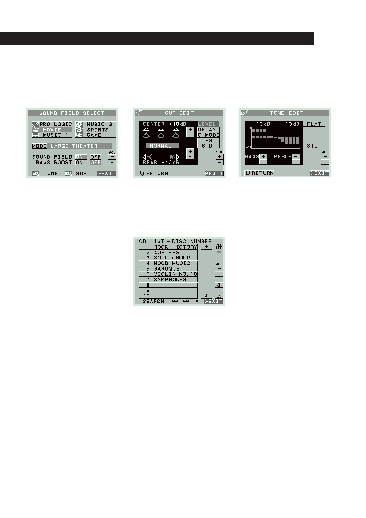
A wide variety of sound fields including Dolby Pro Logic surround
Since the receiver comes preset with 12 different sound fields (like HALL, THEATER, ARENA, etc.), you can enjoy exciting
sound effects simply by choosing one from the SOUND FIELD SELECT screen.
The receiver also incorporates a Dolby Pro Logic decoder, so you can enjoy programs recorded in Dolby Surround with a
surround effect similar to a movie theater.
CD Changer Control
Connecting a Sony CD changer equipped with a Control A1 terminal allows you to access and display the disc information
stored in the CD changer in alphabetical order, numerical order, or by group name. You can also select the disc to be played
discs from the on-screen display using the receiver’s remote.
EN
5
Page 6
Getting StartedIntroduction
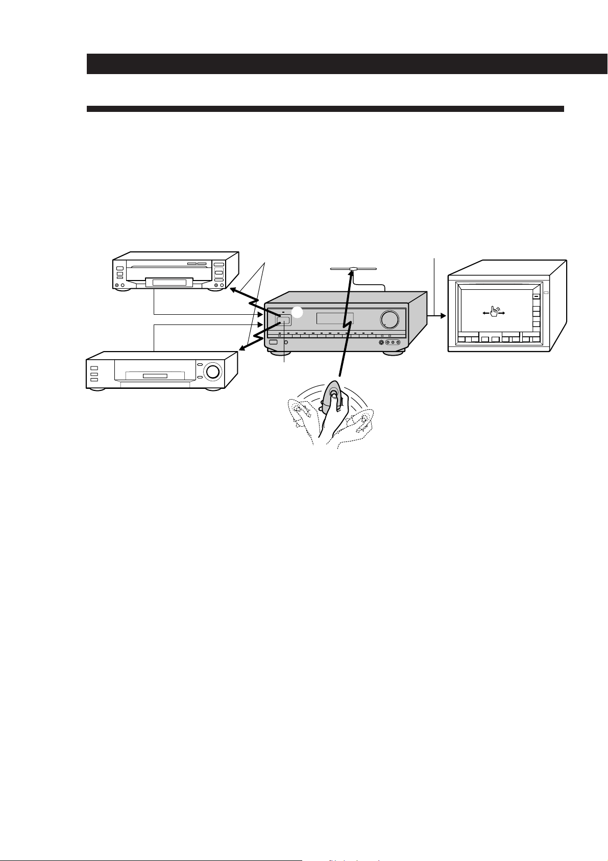
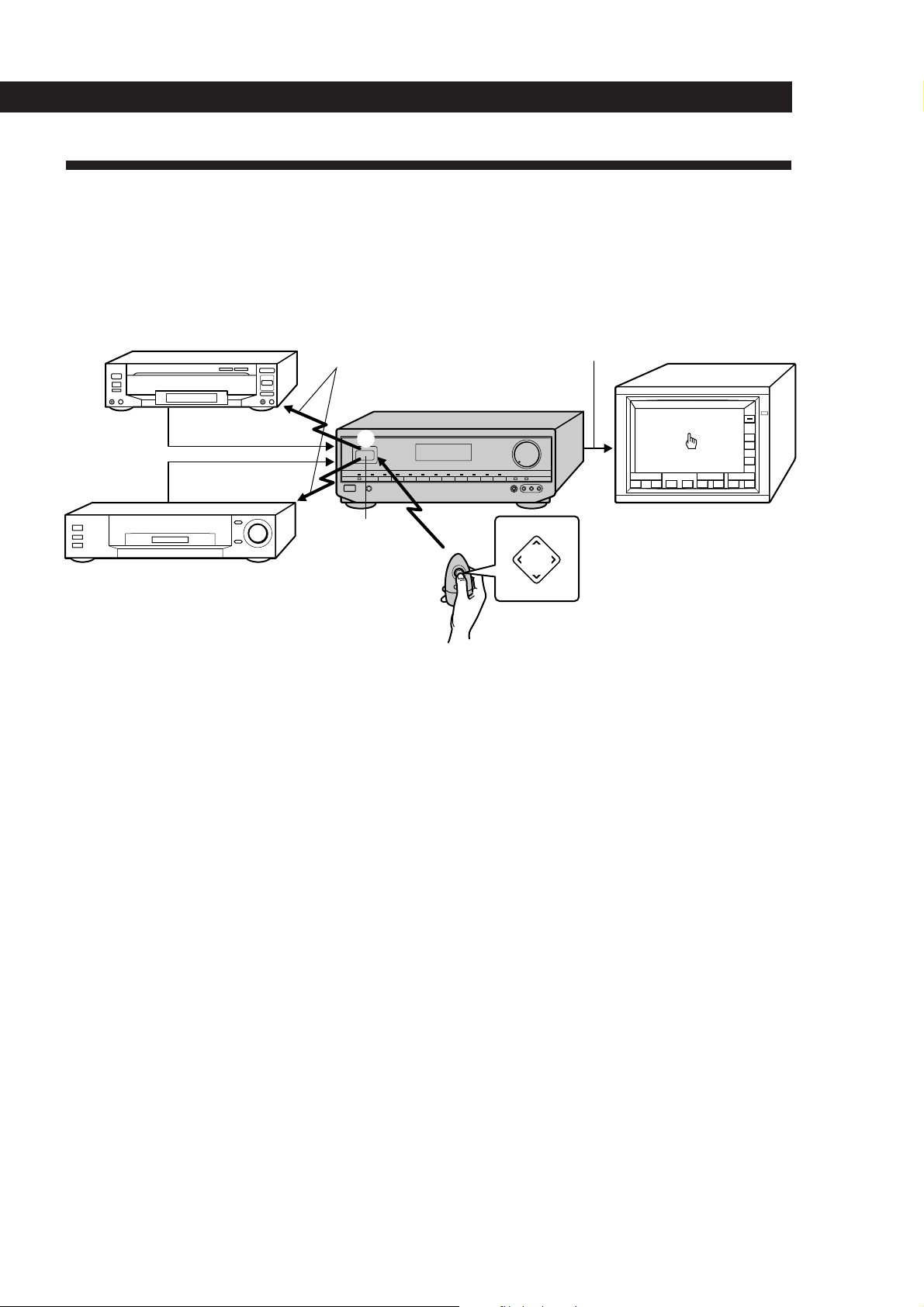
Understanding How the Receiver Works: STR-DE905G
Before you can use the remote to control the receiver, you must connect the remote control (RC) antenna as shown
below.
Steel beams within walls and other metallic objects may interfere with signal reception by the RC antenna. To
prevent this, keep the RC antenna at least 50 cm away from all metallic objects.
Since this receiver uses menu operations, you must connect a TV.
Video signal (Input from source
LD player, etc.
IR control codes
RC antenna
components combined with on-screen
display)
Video signal
Video signal
3
IR repeater
STR-DE905G
FUNCTION
S
O
U
N
D
2
()0pP=+
TV (monitor)
ALL
OFF
VOL
+
–
USERSUB
1
VCR, etc.
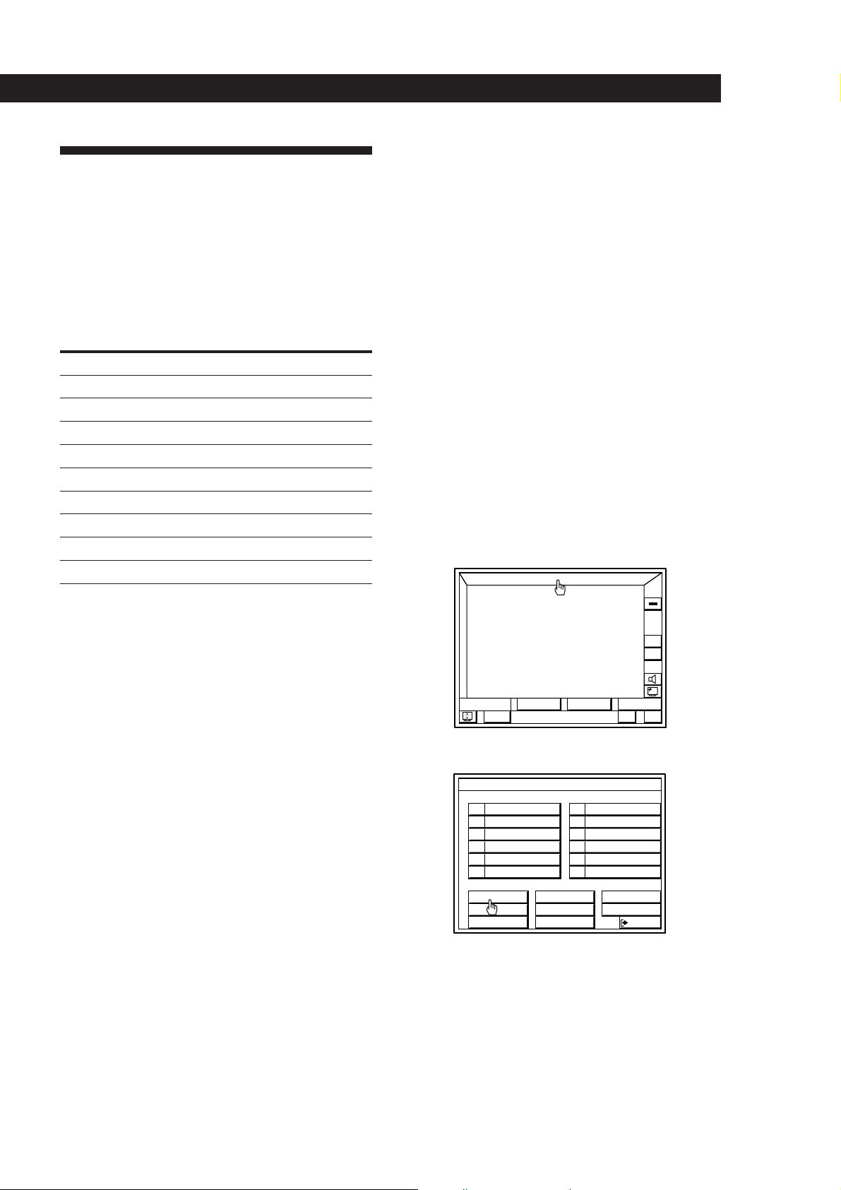
On-screen operation
The remote commander emits a constant radio frequency (RF) signal that conveys any movement of the remote
1
commander to the receiver via the RC antenna (1 above).
2 This controls the movement of the pointer (hand icon) in the on-screen display (2 above).
3 When you move the pointer to an on-screen icon, and press the button on the remote, the infrared (IR) repeater
transmits the corresponding IR control code to the respective program source (3 above).
If the screen flickers or the pointer does not move
The RF signal from the remote is being obstructed and is not reaching the RC antenna (1 above). Reposition the RC antenna or
bring the remote commander closer to the RC antenna.
If the program source fails to respond or is slow to respond
The IR control code from the IR repeater is not fully reaching the infrared receptor on the program source. Connect the extra IR
repeater (supplied) and position it facing the program source (see “IR Repeater Hookups” on page 9).
If some of the programmed on-screen controls are unresponsive or slow, rerecord the IR codes for those buttons ( see
“Registering non-Sony Audio/Video equipment” on page 19).
EN
6
Page 7
Introduction
Understanding How the Receiver Works: STR-DE805G
The remote control supplied with the STR-DE805G uses infrared (IR) rays to command the receiver and control the
on-screen display.
Since this receiver uses menu operations, you must connect a TV.
Video signal (Input from source
LD player, etc.
IR control codes
components combined with on-screen
display)
Video signal
Video signal
STR-DE805G
3
FUNCTION
S
O
U
N
D
Â
2
Mm
µ
()0pP=+
USERSUB
TV (monitor)
Â
PUSH
ENTER
Mm
VCR, etc.
IR repeater
and receptor
1
µ
On-screen operation
1 The remote commander emits an infrared (IR) signal when you press direction control button (1 above).
2 This controls the movement of the pointer (hand icon) in the on-screen display (2 above).
3 When you move the pointer to an on-screen icon, and press the center of the direction control button, the
infrared (IR) repeater transmits the corresponding IR control code to the respective program source (3 above).
If the screen does not appear or the pointer does not move when you press the direction control button
The IR code from the remote is not fully reaching the infrared receptor on the receiver (1 above). Make sure there are no
obstacles between the remote and the receiver.
ALL
OFF
VOL
+
–
If the program source fails to respond or is slow to respond
The IR control code from the IR repeater is not fully reaching the infrared receptor on the program source. Connect the extra IR
repeater (supplied) and position it facing the program source (see “IR Repeater Hookups” on page 9).
If some of the programmed on-screen controls are unresponsive or slow, rerecord the IR codes for those buttons ( see
“Registering non-Sony Audio/Video equipment” on page 19).
EN
7
Page 8
Getting Started
Unpacking
Check that you received the following items with the
receiver:
• FM wire antenna (1)
• AM loop antenna (1)
• Remote commander RM-VP1 (remote) (STR-DE905G
only) (1)
• Remote commander RM-VR1 (remote) (STR-DE805G
only) (1)
• Size AA (R6) batteries (2)
• Remote control (RC) antenna (1) (STR-DE905G only)
• IR repeater (1)
• Video cable (1)
• Getting Started and Basic Operation Guide (1)
• AC plug adapter (for 220 V AC model only) (1)
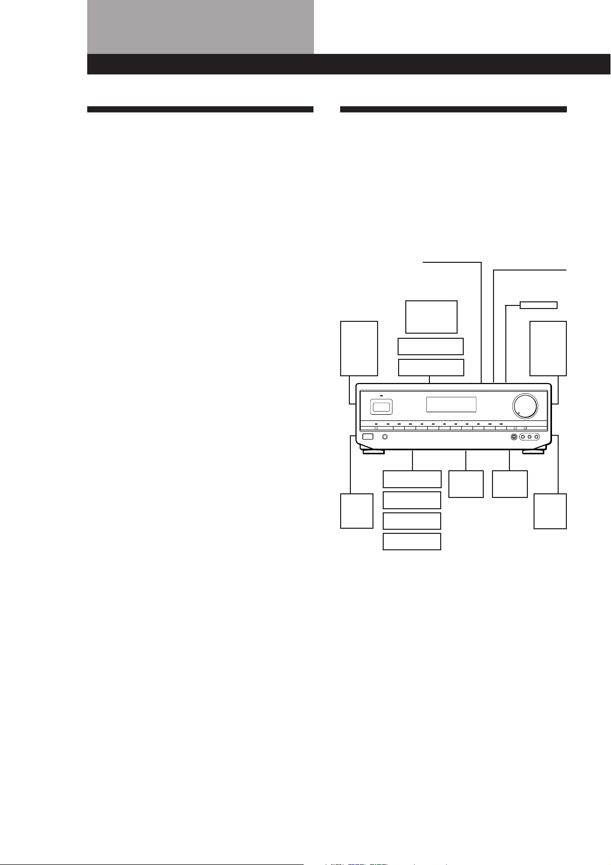
Hookup Overview
The receiver allows you to connect and control the
following audio/video components. Follow the
hookup procedures for the components that you want
to connect to the receiver on the pages specified. To
learn the locations and names of each jack, see “Rear
Panel Descriptions” on page 45.
Speaker
System
Hookups (11)
Front
speaker
(L)
RC Antenna Hookups
(STR-DE905G only) (9)
TV/VCR Hookups (12)
TV
VCR
LD player
Antenna Hookups (10)
AM/FM antenna
IR Repeater
Hookups (9)
Front
speaker
(R)
Center
speaker
Active
woofer
Rear
speaker
(R)
Rear
speaker
(L)
CD player
Tape deck
DAT/MD deck
Turntable
Audio Component
Hookups (10)
Before you get started
• Turn off the power to all components before making
any connections.
• Do not connect the AC power cords until all of the
connections are completed.
• Be sure to make connections firmly to avoid hum
and noise.
• When connecting an audio/video cable, be sure to
match the color-coded pins to the appropriate jacks
on the components: Yellow (video) to Yellow; White
(left, audio) to White; and Red (right, audio) to Red.
EN
8
Page 9
Getting Started
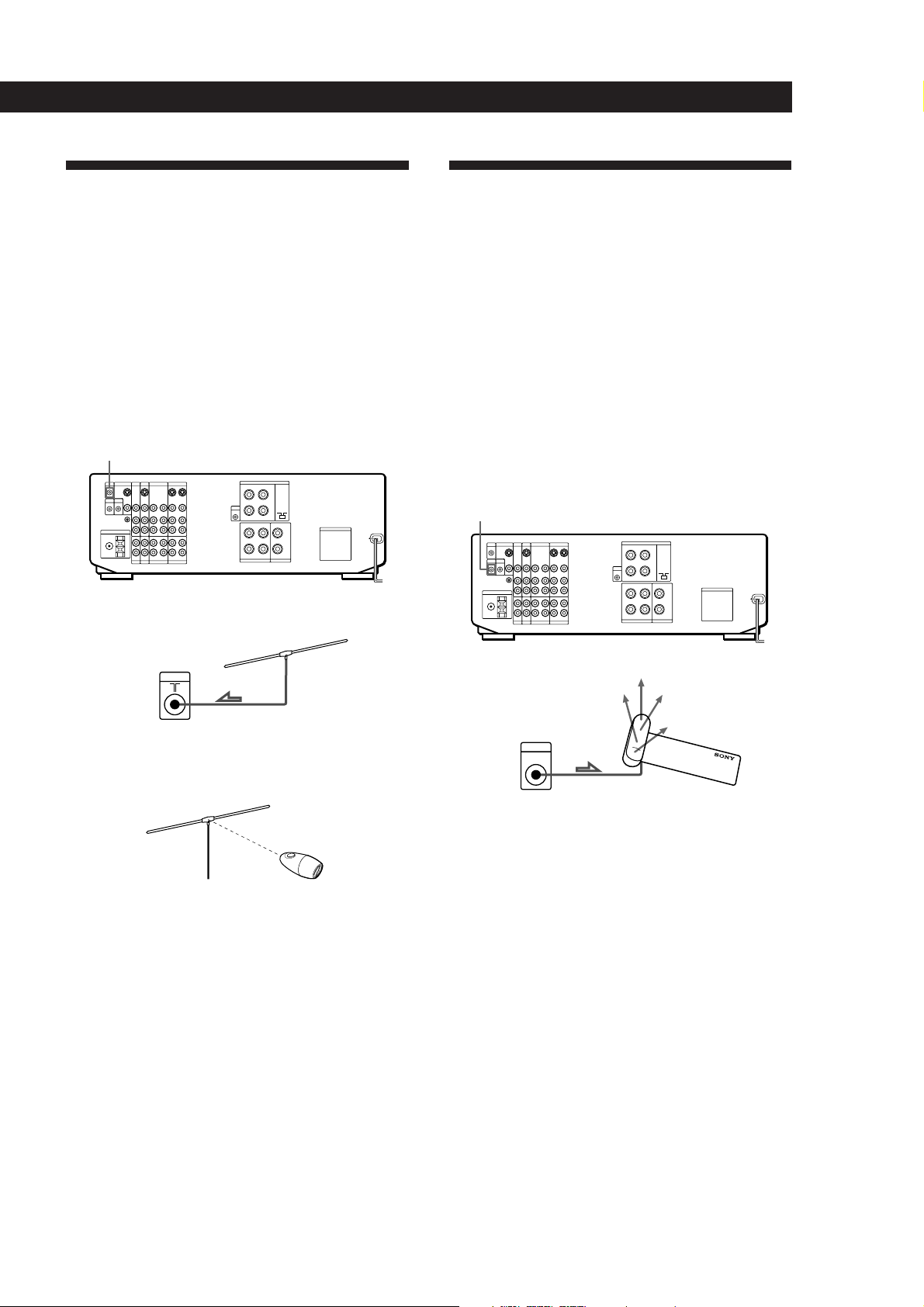
RC Antenna Hookups
(STR-DE905G only)
Overview
This section describes how to connect the supplied RC
antenna to the receiver. Since the remote controls the
unit using radio frequency (RF) signals, you must
connect the remote control (RC) antenna to the unit
before you can use the remote commander.
For the specific location of the terminal, see the
illustration below.
RC ANT
Hookups
IR Repeater Hookups
Overview
This section describes how to connect the supplied
extra infrared (IR) repeater to the receiver. The repeater
emits infrared signals corresponding to those emitted
by the remote controls supplied with the respective
components. Connected this repeater to obtain
additional coverage if you experience difficulty
controlling a certain component using the receiver’s on
screen display (OSD) control functions, or your
installation prevents the repeater on the front panel
from reaching all of the equipment you need to control.
For the specific location of the terminal, see the
illustration below.
IR OUT
Receiver
RC ANT
To maximize RF signal transmission efficiency:
• Position the RC antenna perpendicular to the signal path
of the remote (see below).
• Operate the remote within about 7 m of the RC antenna.
If you have difficulty operating the on-screen display
within this range, reposition the RC antenna for better
reception.
• Keep the RC antenna at least 50 cm away from metallic
objects.
RC antenna
Hookups
Receiver
IR OUT
Notes
• Use the supplied adhesive tape to secure the IR repeater
so that its front faces the equipment to be controlled.
• If you experience trouble controlling the connected
equipment, the infrared (IR) signals transmitted from the
repeater may not be reaching the infrared receptor on the
respective equipment. In such a case, reposition the IR
repeater closer to that piece of equipment.
IR repeater
EN
9
Page 10
Getting Started
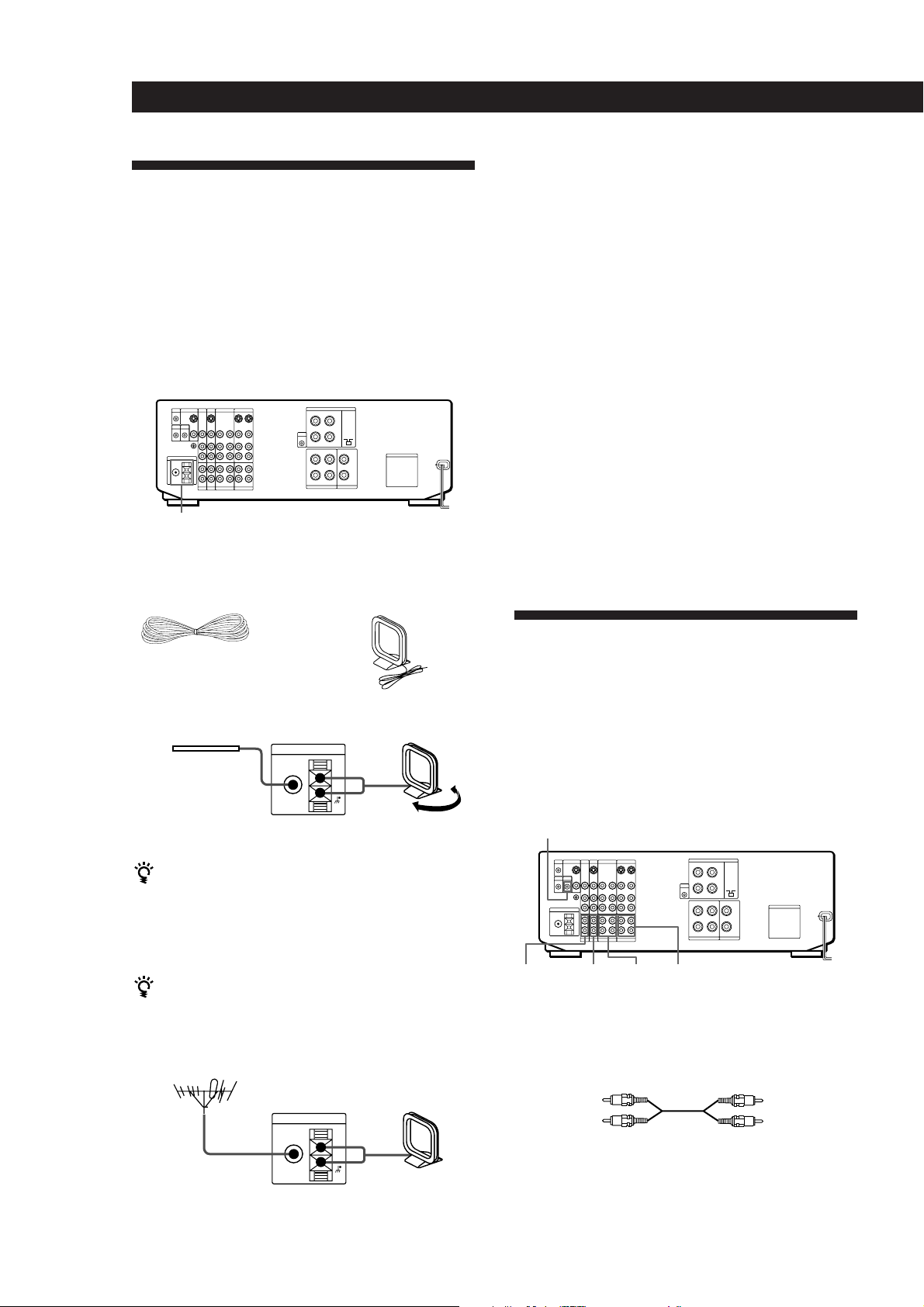
Antenna Hookups
Note
To prevent noise pickup, keep the AM loop antenna away
from the unit and TV set.
Overview
This section describes how to connect AM and FM
antennas to the receiver. If you want to receive radio
broadcasts with the receiver, complete these
connections first, then go to the following pages.
For specific locations of the terminals, see the
illustration below.
ANTENNA
What antennas will I need?
• FM wire antenna
(supplied) (1)
• AM loop antenna
(supplied) (1)
Hookups
Connecting a ground wire
To prevent hum, connect a ground wire (not supplied)
to the y ground terminal. If you’ve connected an
outdoor antenna, be sure to connect the ground for
lightning protection.
Note
The y SIGNAL GND should not be used for this connection.
Where do I go next?
If you want to connect other components, go on to the next
section. If you’re only planning to use the receiver to listen
to the radio, go to “Speaker System Hookups” starting on
page 11.
Audio Component Hookups
Overview
FM wire antenna
After connecting
the wire antenna,
Receiver
ANTENNA
FM
75Ω
COAXIAL
AM loop antenna
AM
keep it as horizontal
as possible.
Adjust the
direction.
If AM reception is poor
We recommend that you purchase and connect the
optional Sony antenna to the unit if reception is
weakened by ferroconcrete used in the construction of
your apartment or building.
If you have poor FM reception
Connect a 75-ohm coaxial cable (not supplied) to an FM
outdoor antenna.
FM outdoor antenna
Receiver
ANTENNA
FM
75Ω
COAXIAL
AM loop antenna
AM
This section describes how to connect your audio
components to the receiver. If you want to use the
receiver as an amplifier, complete these connections.
For specific locations of the jacks, see the illustration
below.
CTRL A1
PHONO DAT/MDCD TAPE
What cords will I need?
Audio cords (not supplied) (1 for each CD player and
turntable; 2 for each tape deck, DAT deck, or MD deck)
White (L)
White (L)
Red (R)Red (R)
10
EN
Page 11
Hookups
The arrow ç indicates signal flow.
CD player
CD player
OUTPUT
LINE
Tape deckReceiver
OUTPUT
DAT/MDReceiver
OUTPUT
Tape deck
DAT/MD
Receiver
L
R
L
R
L
R
TAPE
DAT/MD
IN
CD
INREC OUT
INREC OUT
L
R
INPUT
LINELINE
INPUT
LINELINE
Getting Started
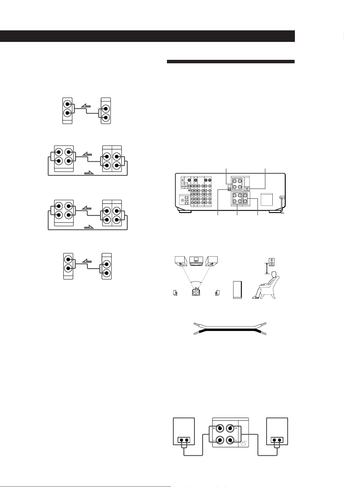
Speaker System Hookups
Overview
This section describes how to connect your speakers to
the receiver. Although front (left and right) speakers
are required, center and rear speakers are optional.
Adding center and rear speakers will enhance the
surround effects. Connecting an active woofer will
increase bass response.
For specific locations of the terminals, see the
L
R
L
R
illustration below.
WOOFER REAR
FRONT SPEAKERS
SPEAKERS
IMPEDANCE
SELECTOR
CENTER
SPEAKER
Turntable
Receiver Turntable
L
R
IN
PHONO
OUTPUT
LINE
L
R
• If your turntable has an earth lead
To prevent hum, connect the earth lead to the y SIGNAL
GND terminal on the receiver.
CONTROL A1 Hookups
• If you have a CONTROL A1 compatible Sony CD player
or tape deck
Use a CONTROL A1 cord (not supplied) to connect the
CTRL A1 jack on the CD player or tape deck to the S-LINK
CTRL A1 jack on the receiver. Refer the separate manual
“CONTROL-A1 Control System” and the Operating
Instructions supplied with your CD player or tape deck
for details.
• If you have a Sony CD changer with a COMMAND
MODE selector
If the CD changer’s COMMAND MODE selector can be
switched between CD 1, CD 2, and CD 3, be sure to set the
command mode to “CD 1” and connect the changer to the
CD terminals on the receiver.
However, if you have a Sony CD changer with VIDEO
OUT terminals, set the command mode to “CD 2” or “CD
3” and connect the changer to a set of the receiver’s video
component terminals (VIDEO 1, VIDEO 2, or LD).
For optimum surround sound effect, place your
speakers as shown below.
Rear speaker
60 - 90 cm
45°
Front speaker
What cords will I need?
Speaker cord (not supplied) (1 for each speaker)
(+)
(–)
(+)
(–)
Twist the stripped ends of the cord about 15 mm. Be sure to
match the speaker cord to the appropriate terminal on the
components: + to + and – to –. If the cords are reversed, the
sound will be distorted and will lack bass.
Hookups
Front speakers
Front speaker
(R)
} ]
Receiver
FRONT SPEAKERS
RL
Front speaker
(L)
} ]
(continued)
11
EN
Page 12
Getting Started
L
R
L
R
TV/DBS
OUTPUT
VIDEO
IN
AUDIO
IN
VIDEO
AUDIO
MONITOR
OUT 1
INPUT
VIDEO
OUT
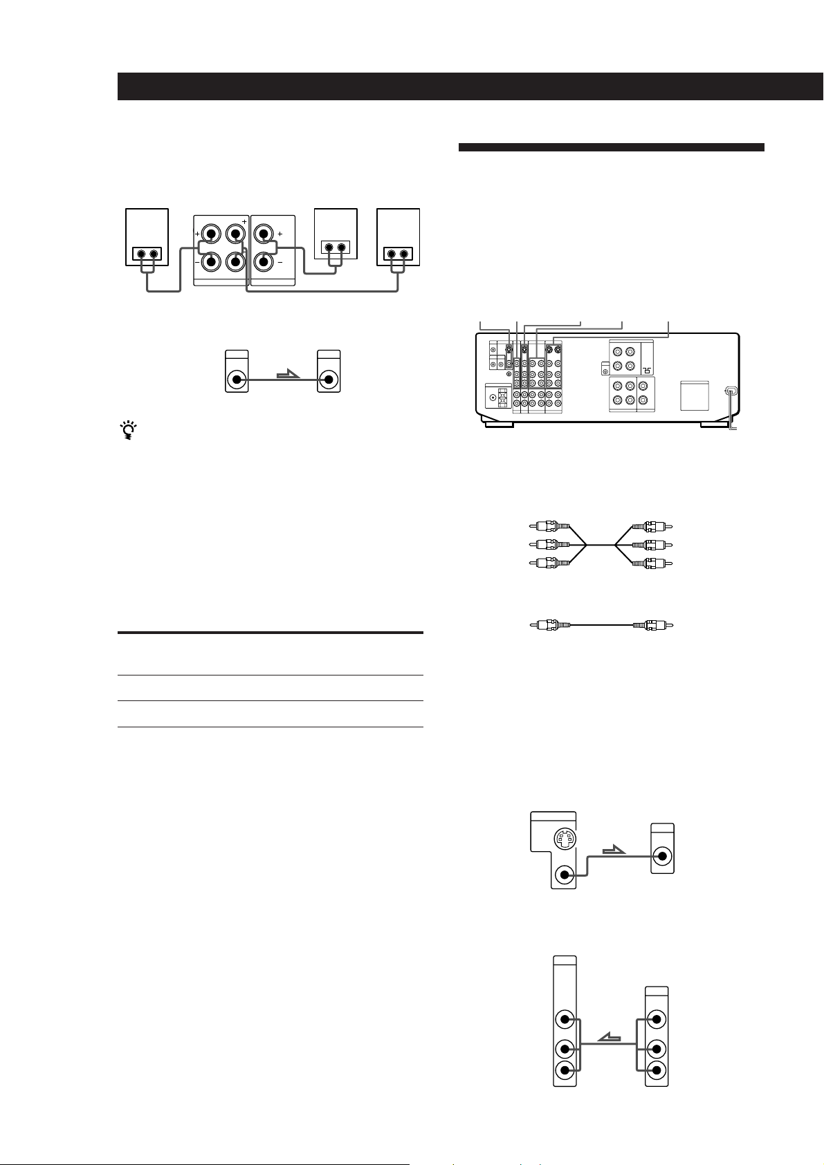
Rear and center speakers
Rear
speaker
(R)
} ]
Receiver
R
} ]
REAR SPEAKERSLCENTER SPEAKER
Center
speaker
} ]
Rear
speaker
(L)
} ]
TV/VCR Hookups
Overview
This section describes how to connect video
components to the receiver. For specific locations of the
jacks, see the illustration below.
Active woofer
Receiver
AUDIO
OUT
Active woofer
INPUTMIX
If your TV monitor uses separate speakers
You can connect one of them to the SURROUND OUT
CENTER terminal for use with Dolby Pro Logic
Surround Sound (see page 32).
Selecting the impedance
Set the IMPEDANCE SELECTOR for the front speakers
as indicated in the table below. Check the instruction
manual of your speakers if you’re not sure of the
impedance. (This information is usually printed on a
label on the back of the speaker.)
if nominal impedance of
your speaker is
Between 4 and 8 ohms
8 ohms or higher
Set IMPEDANCE SELECTOR to
4 Ω
8 Ω
VIDEO 1VIDEO 2LDMONITOR TV/DBS
What cables will I need?
• Audio/video cable (not supplied) (1 for each TV or LD
player; 2 for each VCR)
Yellow
White (L)
Red (R)
Yellow
White (L)
Red (R)
• Video cable (not supplied) (1 for a TV monitor)
Yellow
Yellow
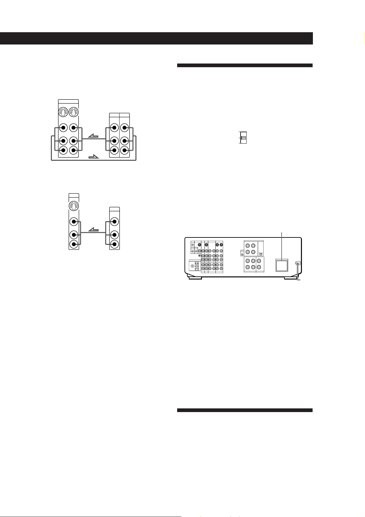
Hookups
The arrow ç indicates signal flow.
Monitor
If you are using your TV as a monitor, do not connect
anything to the TV/DBS IN jacks, unless you have a Sony TV
with TV OUT jacks (see page 25 for details).
Receiver
TV
TV tuner or DBS (Digital Broadcasting Satellites) receiver
Receiver
TV/DBS
12
EN
Page 13
VCR (via the VIDEO 1 jacks)
If you have two VCRs connect the second one to the VIDEO
2 jacks. If one of them has a StarSight tuner, be sure to
connect that one to the VIDEO 1 jacks.
Receiver
VIDEO 1
VIDEO
OUT
VIDEO
INOUT
IN
VCR
OUTPUT
VIDEO VIDEO
INPUT
Getting Started
AC Hookups
If your amplifier has a voltage selector on the rear panel
Your amplifier operates on either 120, 220 or 240 V AC.
Before connecting the unit to a wall outlet, be sure to set the
voltage selector on the rear of the unit to the appropriate
position according to your local power supply.
AUDIO
AUDIO
IN
OUT
L
R
AUDIO AUDIO
L
R
LD player
Receiver
LD
IN
VIDEO
IN
AUDIO
IN
L
R
LD
OUTPUT
VIDEO
AUDIO
L
R
Where do I go next?
Go on to the next section to connect the AC power cord and
complete your home theater system.
220V
240V
120V
x
Connecting the AC power cord
Connect the AC power cord from this receiver and
from your audio/video components to a wall outlet.
If you connect other audio components to the
SWITCHED AC OUTLET(s) on the receiver, the
receiver can supply power to the connected
components so you can turn on/off whole system
when you turn on/off the receiver.
SWITCHED AC OUTLET(s)
/
to a wall
outlet
Caution
Make sure that the power consumption of the component(s)
connected to the receiver’s AC outlet(s) does not exceed the
wattage indicated on the rear panel. Do not connect highwattage electrical home appliances such as electric irons,
fans, or TVs to this outlet.
Where do I go next?
Before you use the␣ receiver, go to the next section to make
sure that all the controls are set to the appropriate positions.
Before You Use Your Receiver
Before you start using your receiver, make sure that
you have:
• Turned MASTER VOLUME to the leftmost
position (0).
• Set the speakers to ON. (For details, see page 44.)
13
EN
Page 14
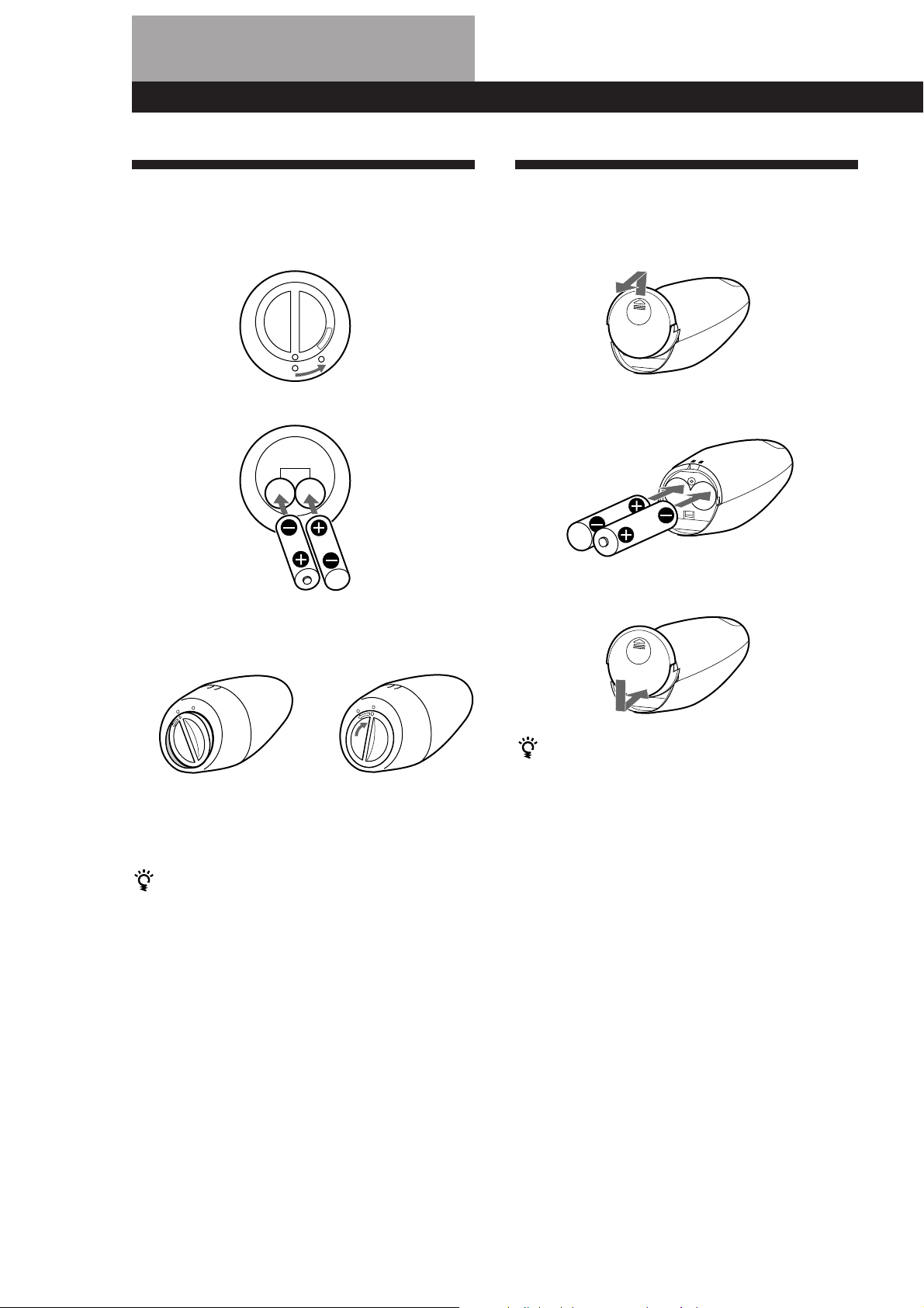
Preparing and Using the Remote
Inserting Batteries Into the
Remote: STR-DE905G
1 Open the cover on the bottom of the remote.
O
P
E
N
÷
2 Insert two size -AA (R6) batteries with correct
polarity (+/–).
3 Close the cover by holding it down (it will be a
little uneven) and turning it to the right.
The cover locks
Inserting Batteries Into the
Remote: STR-DE805G
1 Open the cover on the bottom of the remote.
2 Insert two size -AA (R6) batteries with correct
polarity (+/–).
3 Close the cover.
14
EN
÷
After inserting the batteries into the remote
Place it undisturbed on a flat surface for about 10
seconds to allow the internal circuitry to calibrate.
To avoid damage caused by battery leakage and
corrosion
Remove the batteries when the commander will not be
used for a long time.
Battery life
• Normal operation can be expected about three
months using Sony SUM-3 (NS), and a half year
using Sony AM-3 (NW) alkaline batteries. Since the
remote consumes power whenever you pick it up
and an on-screen display appears, the service life of
the batteries may be less than three months,
depending on how much you handle the remote.
• When the batteries become weak, LOW will appear
on the display during the initial on-screen displays
(but possibly not at the deeper menu levels). When
EMPTY appears, the batteries are almost completely
drained and will soon need to be replaced.
To avoid damage caused by battery leakage and
corrosion
Remove the batteries when the commander will not be
used for a long time.
Battery life
• Normal operation can be expected about three
months using Sony SUM-3 (NS), and a half year
using Sony AM-3 (NW) alkaline batteries. Since the
remote consumes power whenever you pick it up
and an on-screen display appears, the service life of
the batteries may be less than three months,
depending on how much you handle the remote.
• Do not expose the remote sensor to direct sunlight or
lighting apparatuses. Doing so may cause a
malfunction.
Page 15
Preparing and Using the Remote
Preventing Interference
Between Multiple Remotes
(STR-DE905G only)
If you use two or more receivers at the same time,
interference may occur between the RF signals, causing
the units to operate erratically. You can prevent this by
giving all units a unique security number which
distinguishes the signal of each unit from the others.
Follow the procedure below to assign a security
number to each unit.
1 Turn off the power to the unit.
2 Turn on the unit again while simultaneously
holding down the PHONO, CD, and TUNER
buttons on the front panel. “SECURITY No.”
appears in the display. Enter a number from 0 to
15 by pressing PHONO, CD or TUNER on the
front panel. Make sure that the number is
different from the security code of the other units.
3 After a few seconds, “SECURITY OK!” appears,
indicating that the code has been recorded.
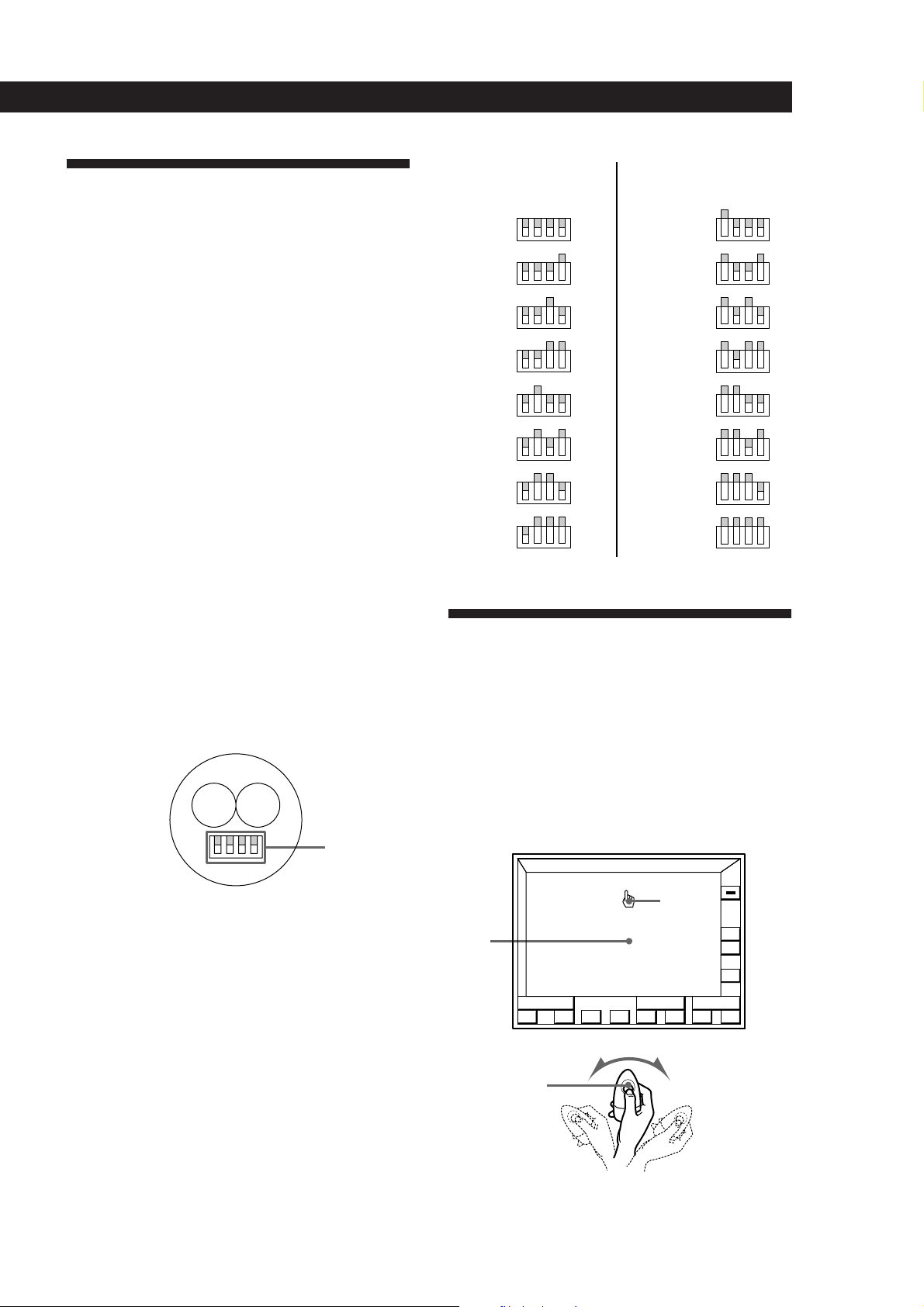
SECURITY
NO.
0
1
2
3
4
5
6
7
Remote
commander
4321
4321
4321
4321
4321
4321
4321
4321
SECURITY
NO.
8
9
10
11
12
13
14
15
How to Use the Remote:
Remote
commander
4321
4321
4321
4321
4321
4321
4321
4321
4 Enter the same security number into the remote.
To do this, open the battery compartment and
remove the batteries. You will see a set of yellow
switches as shown below.
Yellow
switches
Use the tip of a pen or some other pointed object
to flip up the appropriate switches for each digit
of the security number (refer to the chart on the
following page). Note that all switches are down
for zero, and all switches are up for fifteen.
5 Reinsert the batteries and place the remote on a
flat surface for about 10 seconds.
STR-DE905G
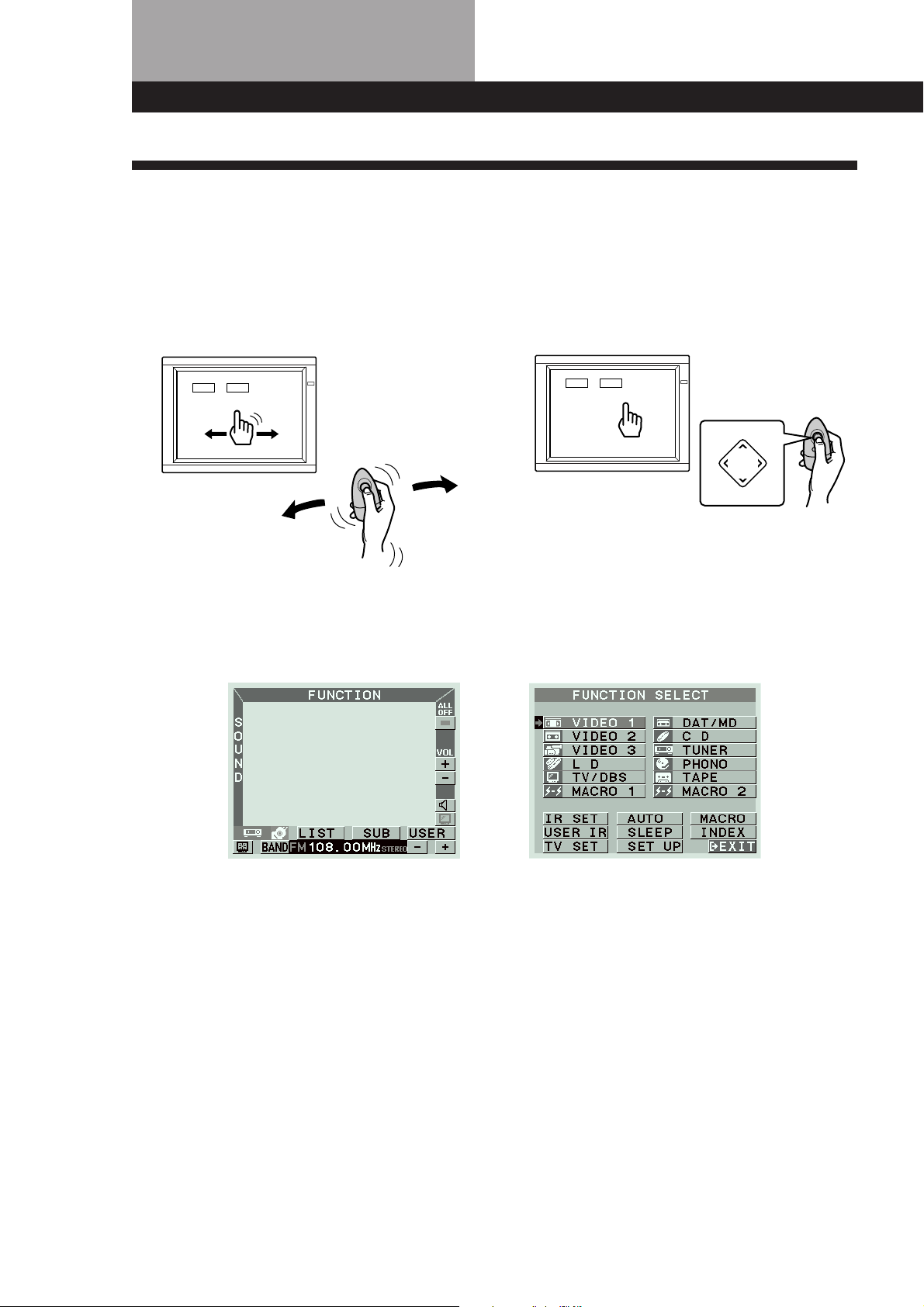
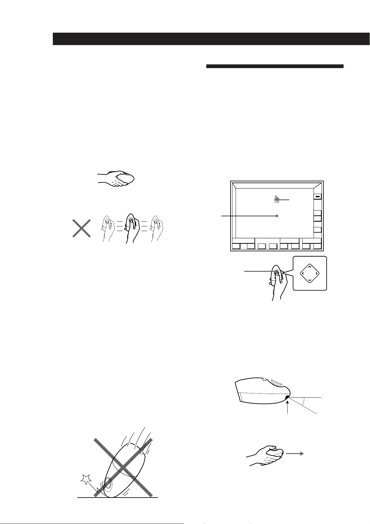
The supplied remote lets you perform almost all of the
receiver operations. Operation is simple, just move the
remote in the direction you want to move the pointer
(hand shaped icon) on the on-screen display. Position
the pointer so that the finger tip is positioned on one of
the on-screen items, then press and quickly release the
button on the remote to “click” the item.
Blank
area
Click button
FUNCTION
S
O
U
N
D
()0pP=+
Pointer
ALL
OFF
VOL
+
–
USERSUB
To turn on the receiver
Press the click button on the remote once or twice to turn on
the unit.
(continued)
15
EN
Page 16
Preparing and Using the Remote
()0pP=+
FUNCTION
+
–
VOL
ALL
OFF
USERSUB
S
O
U
N
D
PUSH
ENTER
Mm
Â
µ
If the on-screen display does not appear even after the
batteries have been inserted into the remote (see page
14), reinsert the batteries and place the remote on a flat
surface for about 10 seconds.
Hints on handling the remote
• A slight wrist movement is all you need to direct the
pointer. (See previous illustration.)
• Hold the remote with its “click” button facing up, as
shown below. If the click button is oriented
diagonally, the pointer will not move in the same
direction that you move the remote.
How to Use the Remote:
STR-DE805G
The supplied remote lets you perform almost all of the
receiver operations. Operation is simple, press the
direction control button on the remote once to recall
the on-screen display, then press the corner of the
direction control pad representing the direction you
want to move the pointer (hand shaped icon) on the
on-screen display. Position the pointer so that the
finger tip is positioned on one of the on-screen items,
then press and quickly release the center of the
direction control button to “click” the item.
• The pointer will not move if you move the remote
along a flat plane as shown below.
• The on-screen display disappears automatically after
a few seconds when you place the remote on a flat
surface.
To make the on-screen display disappear faster,
position the pointer in the blank area, hold down the
click button to vanish the display, then place the
remote on a flat surface and release the click button.
To recall the on-screen display, pick up the remote.
Notes
• The position of the pointer freezes when you hold down
the click button.
• If the pointer begins drifting on the screen even while the
remote is stationary, place the remote on a flat surface
until the on-screen display disappears. The pointer
should behave normally the next time you use the remote.
• If your hand is very dry, the on-screen display may not
appear when you touch the click button. In this case, press
the click button.
Pointer
Blank
area
Direction
control
button
To turn on the receiver
Press the direction control button on the remote once or
twice to turn on the unit.
Hints on handling the remote
• Do not cover the IR emitter when operating the
remote.
Caution
Since the remote contains delicate circuitry and parts, do not
subject it to sudden changes in temperatures or to shock.
• Hold the remote with its direction control button
facing up, as shown below.
Be sure your hand
does not cover this part
IR rays
30°
• To make the on-screen display disappear, position
the pointer in the blank area, and press the center of
the direction control button.
16
EN
Page 17
Registering a TV or Monitor
Preparing and Using the Remote
4 Click OTHER TV (or click “Sony TV” for a Sony
TV).
Australian, Malaysian, and Singaporean models
Registering a Sony TV or monitor
If your Sony TV can be controlled by an infrared
remote, and it is connected to the receiver by it’s
VIDEO 1 video input jack, IR code registration is
unnecessary.
The following cases require registration of a Sony TV
• If your Sony TV is connected via a different video
input jack (such as VIDEO 2).
To ensure proper operation, follow steps 1 to 3 below,
click VIDEO 1 2 3 to specify the correct video input in step
4, then click RETURN or EXIT.
• If you are using a wide Sony TV (except for
customers in Australia, Malaysia, and Singapore).
To ensure proper operation, follow steps 1 to 3, click
WIDE in step 4, then click RETURN or EXIT.
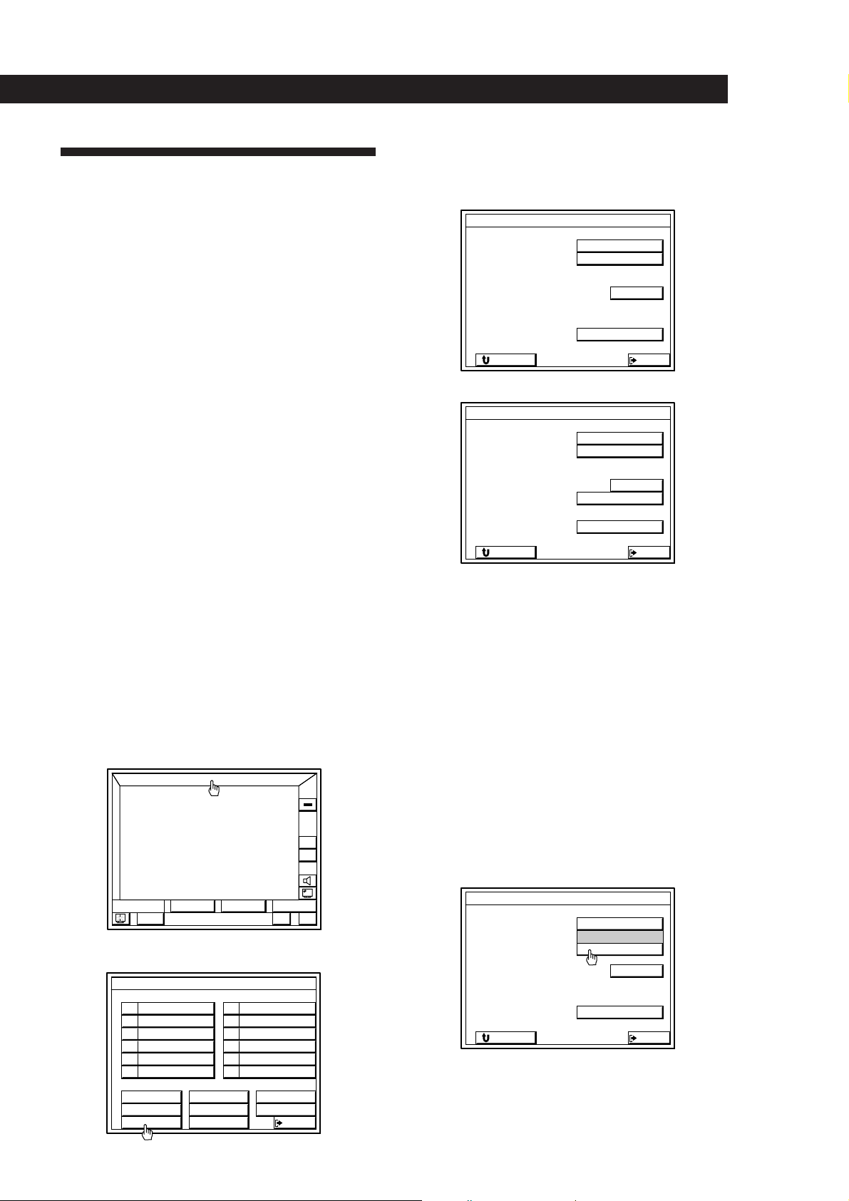
Registering a non-Sony TV or monitor
Complete the following procedure to set the receiver to
turn on your TV or monitor automatically whenever
you turn on the receiver.
Registration
1 Turn on the receiver and the TV set.
Make sure the input selector on the TV set is set to
the video input.
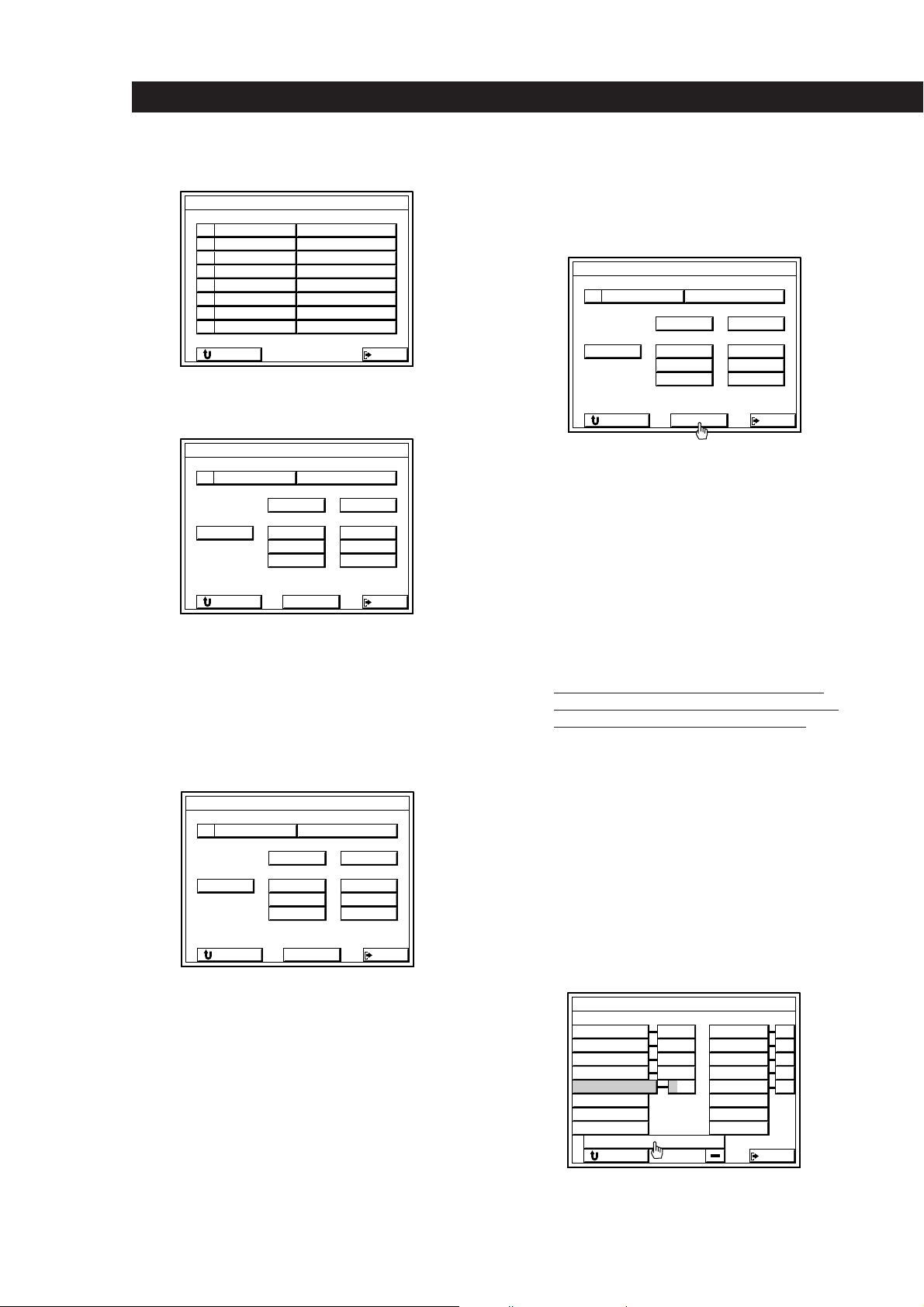
2 Click FUNCTION in the main menu.
TV MONITOR SET
TV IR SET
TV INPUT
GRAPHIC POSITION
RETURN
VIDEO
Sony TV
OTHER TV
1
32
EXIT
Other models
TV MONITOR SET
TV IR SET
TV INPUT
TV SIZE
GRAPHIC POSITION
RETURN
Sony TV
OTHER TV
VIDEO
1
NORMAL WIDE
32
EXIT
If you connected the receiver to the VIDEO 2, or 3
jacks on your TV or monitor
Click VIDEO 1 2 3 to specify the correct video input.
If you are using a wide TV
Click WIDE to specify WIDE.
(This operation is unnecessary for customers in
Australia, Malaysia, and Singapore.)
If you are using a Sony TV
The IR codes are programed automatically and
registration is complete (click RETURN or EXIT).
S
O
U
N
D
BAND
3 Click TV SET.
VIDEO 1 DAT/MD
VIDEO 2
VIDEO 3
L D
MACRO 1
TV SET
FUNCTION
LIST
FM 102.50MHz
FUNCTION SELECT
STEREO
CD
TUNER
PHONO
TAPETV / DBS
MACRO 2
USERSUB
EXIT
ALL
OFF
VOL
+
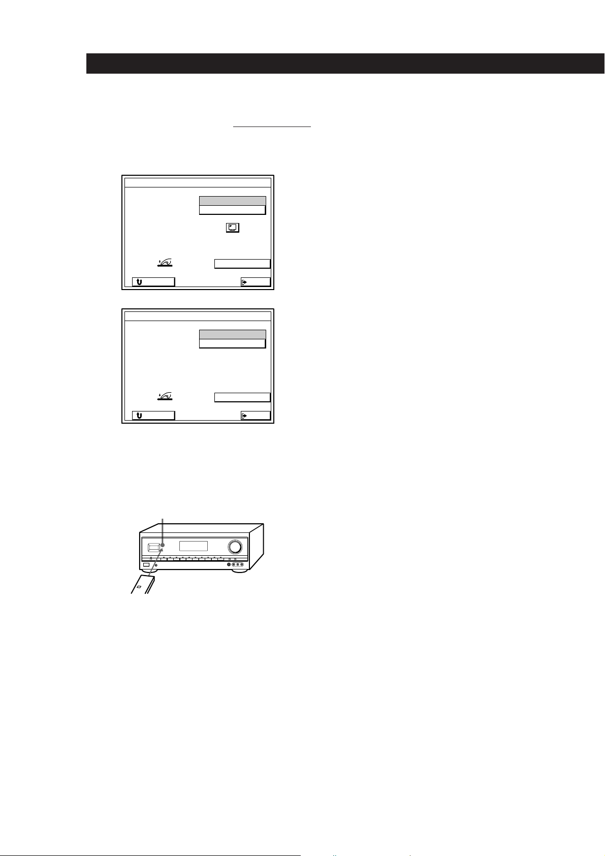
–
+–
Before going to step 5, cover the IR sensor on the
TV to prevent accidental operation. Otherwise,
the on-screen display may be turned off during
the programing procedure.
5 Click START.
TV MONITOR SET
TV IR SET
TV INPUT
GRAPHIC POSITION
RETURN
Sony TV
OTHER TV
VIDEO
START
1
32
EXIT
(continued)
17
EN
Page 18
Preparing and Using the Remote
6 When “PUSH YOUR COMMANDER” appears on
the TV screen, press the button
that corresponds to the highlighted control button
(e.g., POWER).
Australian, Malaysian, and Singaporean models
TV IR SET
TV IR SET
WIDE TV DISPLAY MODE
PUSH YOUR COMMANDER
RETURN
Other models
TV IR SET
TV IR SET
PUSH YOUR COMMANDER
RETURN
When programing the IR code, point the remote
at the IR sensor on the receiver from a distance no
greater than 10 cm and hold down the button on
the remote for about 5 seconds until the
instruction “RELEASE YOUR COMMANDER”
appears.
IR sensor
on the TV's remote
TV POWER
VIDEO 1
CODE CLEAR
EXIT
TV POWER
VIDEO 1
CODE CLEAR
EXIT
If your TV set does not have an independent input
selector button or has a cyclic input selector button
Click EXIT to return to the main menu.
The TV’s input can not be switched automatically when
you turn on the receiver. Switch the TV to the video
input manually. If you programed an IR code for the
VIDEO 1 button, follow the instructions in “To erase a
specific IR code” below to erase the VIDEO 1 code.
To exit to the main menu
Click EXIT.
To return to a previous menu
Click RETURN.
To erase TV IR codes
Click CODE CLEAR.
• To erase a specific IR code
1 Click SINGLE IR CODE CLEAR
2 Click the button you want to clear.
“Are you sure?” appears for confirmation.
3 Click YES to erase the code.
“CODE CLEAR!” appears in the display.
To stop before erasing a code, click NO.
To erase another code repeat steps 2 and 3.
• To erase all the TV IR codes
1 Click TV IR CODE CLEAR.
“Are you sure?” appears for confirmation.
2 Click YES to erase the codes.
“CODE CLEAR!” appears in the display. To stop before
erasing the codes, click NO.
• To erase all the IR codes.
1 Click ALL IR CODE CLEAR.
“Are you sure?” appears for confirmation.
2 Click YES to erase the codes.
“CODE CLEAR!” appears in the display. To stop before
erasing all the codes, click NO.
18
EN
Keep the remote pointed horizontally at the IR
sensor until the code is programed.
If you tilt or move the remote during the
programing process, the IR code may not be
programed correctly.
7 Repeat this procedure for the remaining buttons
that appear on the TV screen. If an IR code was
not programed correctly, the IR code setting
indicator will flash.
If your TV set’s remote has an independent input
selector button (e.g., VIDEO 1)
Program the IR code of this button when the VIDEO 1
button appears. When you turn on the receiver, the TV
switches to the video input automatically.
Note
Some IR codes may not have been successfully programed,
even if “RELEASE YOUR COMMANDER” appears on the
TV screen. In this case, try programing the IR code again. If
the IR code still cannot be programed, follow the procedure
described in “Programming Other Infrared (IR) Codes
(USER IR setting)” on page 22.
To change from another manufacturer’s TV set to a Sony
TV set
Connect the receiver’s MONITOR OUT jack to the VIDEO 1
input jack of the Sony TV set. Follow steps 1 to 3, then click
SONY TV in step 4. Click VIDEO 1 2 3 and/or WIDE to
specify VIDEO 1 and/or WIDE if necessary. Then click
RETURN or EXIT.
Page 19
Registering Audio/Video
Equipment
Registering Sony audio/video equipment
If your Sony audio and video equipment can be
controlled by an infrared remote, simply connect them
to the jacks shown on the following table, registration
is unnecessary.
Receiver jacks Equipment to be connected
VIDEO 1 Sony VTR 3 (VHS)
VIDEO 2 Sony VTR 1 (BETA)
VIDEO 3 Sony VTR 2 (8 mm)
LD Sony LD player
TV/DBS Sony DBS receiver
DAT/MD Sony DAT deck
CD Sony CD player (CD 1)
TAPE Sony Tape deck
MONITOR Sony TV (via its VIDEO 1 jack)
Preparing and Using the Remote
Registering non-Sony audio/video
equipment
If you connect audio or video equipment made by
another manufacturer, you must program the IR codes
used by the equipment before you can control it
through the receiver.
You can program up to 120 IR codes, including user IR
codes; however, depending on the type of codes
recorded, the maximum limit may be less than 100. It
may be difficult or impossible to program up to 120
codes under the following conditions:
• When programing IR codes of special remotes such
as card type remotes, or remotes for household
appliances such as air conditioners.
• When programing from remotes with weak batteries.
• When programing IR codes that have been
programed to a programmable remote (i.e., any IR
code not originally supplied in the respective
remote).
Registration
Click FUNCTION in the main menu.
1
FUNCTION
ALL
OFF
The following cases require registration of Sony products
• When connecting a Sony MD deck to the DAT/MD
jacks.
• When connecting a Sony audio product with
CONTROL-A1 compatibility.
• When connecting a Sony product to jacks other than
those specified in the previous table (e.g., when
connecting a Sony LD player to the VIDEO 3 jacks).
• When exchanging non-Sony audio or video
equipment with a Sony product.
Notes
• If your VCR has a COMMAND CODE selector switch (for
VTR1, VTR2, or VTR3), set the switch to the applicable
setting. If your VCR has a built-in StarSight tuner, you
must set the COMMAND CODE selector switch to VTR 3.
• If your CD changer has a COMMAND MODE selector
switch (for CD 1, CD 2, or CD 3), normally it should be set
to “CD 1”. However, if your CD changer has VIDEO OUT
terminals, set the command mode to “CD 2” or “CD 3”
(“CD 3” should only be used when making CONTROL-A1
connections).
S
O
U
N
D
BAND
2 Click IR SET.
VIDEO 1 DAT/MD
VIDEO 2
VIDEO 3
L D
MACRO 1
IR SET
LIST
FM 102.50MHz
FUNCTION SELECT
STEREO
CD
TUNER
PHONO
TAPETV / DBS
MACRO 2
VOL
+
–
USERSUB
+–
EXIT
(continued)
19
EN
Page 20
Preparing and Using the Remote
3 Click the appropriate function.
IR CODE SETTING
VIDEO 1 Sony VTR3
VIDEO 2
VIDEO 3
LD
TV/DBS
DAT/MD
CD Sony CD1
TAPE Sony TAPE
RETURN
Sony VTR1
Sony VTR2
Sony LD
Sony DBS
Sony DAT
EXIT
4 Click “Sony” for a Sony product or OTHER for a
non-Sony product.
IR CODE SETTING
OUTPUT IR
Sony
RETURN
OTHERMAKER
EXIT
If the program source is a Sony product
The IR codes are programed automatically and
registration is complete (click RETURN or EXIT).
To take advantage of CONTROL-A1 compatible audio
components, such as multi-disc CD players, click
CONTROL-A1 to select CONTROL-A1.
5 Click the respective program source.
IR CODE SETTING
If the equipment is not a video deck or laser disc
player
Cover the IR sensor on the equipment to prevent
accidental operation during the programing procedure,
click START, then go to step 6.
IR CODE SETTING
OUTPUT IR
VCR
RETURN
Sony
TV
LD
CD
START
OTHERMAKER
TAPE
DAT
MD
EXIT
If the equipment is a video deck or laser disc player:
1 Click START.
A list of other manufacturers appears.
2 Click the manufacturer of the respective equipment
and the IR codes for that program source are
registered automatically. (If the manufacturer is not
listed, cover the IR sensor on the equipment to
prevent accidental operation during the programing
procedure, click “OTHER”, then go to step 6).
3 Click TEST.
If the selected program source turns on, it means the
IR codes have been registered. This ends the
procedure.
If the program source does not turn on, click the
number button beside the manufacturer’s name to
select another number, then click TEST again. If the
program source still does not turn on, cover the IR
sensor on the equipment to prevent accidental
operation during the programing procedure, click
“OTHER”, then go to step 6.
20
EN
OUTPUT IR
VCR
RETURN
Sony
TV
LD
CD
OTHERMAKER
TAPE
DAT
MD
EXIT
When using a video deck from another manufacturer
(Australian, Malaysian, and Singaporean models)
Check to see if the supplied remote uses -/-- or 1- and 2buttons to enter 2 digit TV channels.
Since the -/-- or 1- and 2- codes are not preprogrammed in this unit, do the following operations to
program these codes manually.
1 Select the manufacturer (as shown in step 2 above).
2 Click -/-- 2- CODE SET.
VCR MAKER SETTING
EMERSON
FISHER
PANASONIC
TOSHIBA
MISTUBISHI
GRUNDIG
HITACHI
PHILIPS
– / – – 2 – CODE SET
RETURN
1 2 3 4
1 2
1 2
1 2 3
TEST
AKAI
GE
JVC
RCA
SANYO
SHARP
ZENITH
OTHER
1 21 2 3 4
1 2
1 2
1 2
1 2
EXIT
Page 21
Preparing and Using the Remote
3 When “PUSH YOUR COMMANDER” appears on the
TV screen, press the button on your VCR’s remote
that corresponds to the control button highlighted on
the TV screen (see step 6 for details).
–/–– 2– CODE SETTING
– / ––
1 –, CODE
2 –
PUSH YOUR COMMANDER
RETURN
CODE
– / ––
2 –
CODE CLEAR
EXIT
6 When “PUSH YOUR COMMANDER” appears on
the TV screen, press the button
video equipment’s remote that corresponds to the
control button highlighted on the TV screen.
is the POWER switch.
IR CODE SETTING
1 9 2
10/0
PUSH YOUR COMMANDER
RETURN
)(0pP=+
3
4
>10
REC
When programing the IR code, point the remote
at the IR sensor on the receiver from a distance no
greater than 10 cm and hold down the button on
the remote for about 5 seconds until the
instruction “RELEASE YOUR COMMANDER”
appears and the IR code setting indicator turns
off.
IR sensor
Keep the remote pointed horizontally at the IR
sensor until the code is programed.
If you tilt or move the remote during the
programing process, the IR code may not be
recorded correctly.
Repeat this procedure for the remaining buttons
After you’ve programed all the IR codes, the IR CODE
SETTING menu reappears.
on your audio/
5 6 7 8
CODE CLEAR
EXIT
To program special IR codes that do not appear as
on-screen controls
See “Programming Other Infrared (IR) Codes (USER IR
setting)” on page 22.
7 Repeat steps 3 to 6 to program IR codes from
other program sources.
To exit to the main menu
Click EXIT.
To return to a previous menu
Click RETURN.
To erase IR codes
Click CODE CLEAR.
• To erase a specific IR code
1 Click SINGLE IR CODE CLEAR
2 Click the button you want to clear.
“Are you sure?” appears for confirmation.
3 Click YES to erase the code.
“CODE CLEAR!” appears in the display.
To stop before erasing a code, click NO.
To erase another code repeat steps 2 and 3.
• To erase all the IR codes for the current component (e.g.,
OTHER CD).
1 Click (OTHER CD) CODE CLEAR.
“Are you sure?” appears for confirmation.
2 Click YES to erase the codes.
“CODE CLEAR!” appears in the display.
To stop before erasing the codes, click NO.
• To erase all the IR codes.
1 Click ALL IR CODE CLEAR.
“Are you sure?” appears for confirmation.
2 Click YES to erase the codes.
“CODE CLEAR!” appears in the display.
To stop before erasing all the codes, click NO.
If the IR codes do not operate as expected
• Perform the programing operation(s) again to make sure
the IR codes were programmed correctly.
• If you experience difficulty operating the INPUT, number,
or ENTER buttons of a video deck or laserdisc player after
automatic registration from the manufacturer list in step 5.
Program the IR codes for that equipment manually as
shown in step 6.
• On some laser disc players made by other manufacturers,
the ) and 0 buttons may not operate correctly even
after automatically registration from the manufacturer list
in step 5. If this happens, perform step 6 to manually
program the IR codes for the ) and 0 buttons, as well
as any other buttons that you want to use with the laser
disc player.
• If you register a playback source as TOSHIBA 2 or RCA 2,
you cannot turn the TV set on or off using the receiver’s
remote (the power will not go on when you click TEST).
(continued)
21
EN
Page 22
Preparing and Using the Remote
EXIT
USER IR CODE SETTING
A
F
K
P
U
B
G
L
Q
V
C
H
M
R
W
D
I
N
S
X
E
J
O
T
Y
1
4
7
/
Z
2
5
8
0
–
3
6
9
*
+
bB
RETURN
CAPS
• Some IR codes may not have been successfully
programed, even if “RELEASE YOUR COMMANDER”
appears on the TV screen. In this case, try programing the
IR code again. If the IR code still cannot be programed,
follow the procedure described in “Programming Other
Infrared (IR) Codes (USER IR setting)” on page 22.
• The unit may not be able to record IR codes with special
waveforms produced on some remotes.
Notes
• Do not register the same type of component (i.e., an LD
player) at several different functions.
• The unit emits an IR signal that cancels the automatic
playback function of program sources, such as laser disc
and CD players, designed to start playing the moment
they are turned on. To activate the auto play feature, set
the receiver’s AUTO PLAY function to on.
• Keep the infrared sensor away from fluorescent light or
direct sunlight. Otherwise, the IR codes may not be
recorded.
• Even if the power cord has been disconnected from the
AC power outlet, recorded IR codes will stay in the
memory for approximately two weeks. If they disappear,
“ALL CLEAR!” will appear on the TV screen the next time
you turn on the receiver.
• Do not operate the remote supplied with the STR-DE805G
when “PUSH YOUR COMMANDER” appears on the TV
screen in step 6. Programing IR codes from the supplied
remote may cause the STR-DE805G to malfunction.
Programming Other Infrared
(IR) Codes (USER IR setting)
Use the USER IR CODE SETTING menu to program
any IR codes that could not be programed in
“Registering Audio/Video Equipment”. These can
include codes for audio and video equipment, as well
as other types of equipment, made by almost any
manufacturer. The following procedure lets you to
program up to 20 USER IR codes.
1 Click FUNCTION in the main menu.
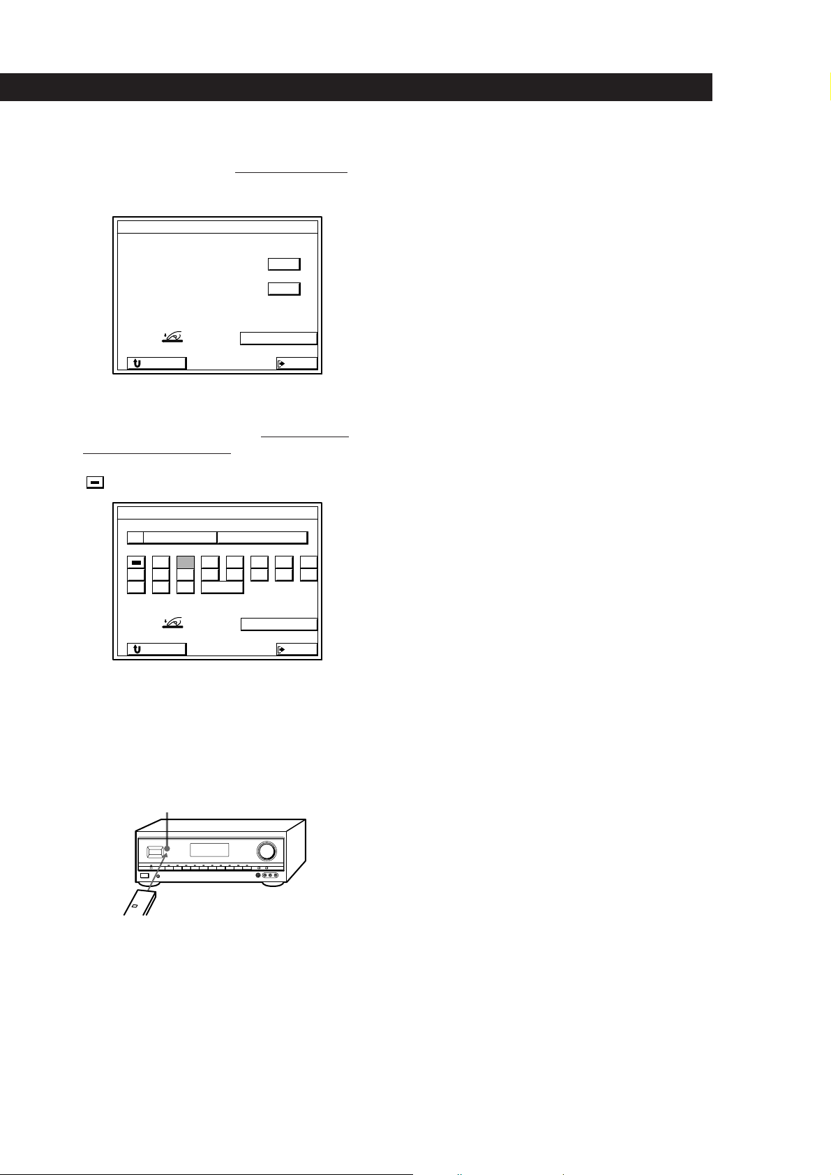
2 Click USER IR.
FUNCTION SELECT
VIDEO 1 DAT/MD
VIDEO 2
VIDEO 3
L D
MACRO 1
USER IR
3 Click A B C D to select a user IR code page, then
click INDEX.
CD
TUNER
PHONO
TAPETV / DBS
MACRO 2
EXIT
USER IR CODE SETTING
A B C D
INDEX
RETURN
EXIT
4 Spell out a name for the IR code by clicking each
character in order. The name is stored
automatically.
22
EN
To enter a space
Click the space bar.
Page 23
Preparing and Using the Remote
To switch between upper and lower case letters
Click CAPS.
If you make a mistake
Click ? or / to move the cursor to the character to be
changed, then click the correct character (or click the
space bar to erase the character).
5 After entering the name, click RETURN to go back
to the USER IR CODE SETTING menu.
Repeat steps 3 through 5 until you enter the
names of all the IR codes you want to program.
6 Click the name of the first IR code.
USER IR CODE SETTING
LIGHT 1
LIGHT 2
LIGHT 3
LIGHT 4
RETURN
A B C D
EXIT
Before going to step 7, cover the IR sensor on the
respective equipment to prevent accidental
operation during the programing procedure.
7 Click on START.
When “PUSH YOUR COMMANDER” appears on
the TV screen, press the button you want to
program.
USER IR CODE SETTING
LIGHT 1
LIGHT 2
LIGHT 3
LIGHT 4
PUSH YOUR COMMANDER
RETURN
When programing the IR code, point the remote
at the IR sensor on the receiver from a distance no
greater than 10 cm and hold down the button on
the remote for about 5 seconds until the
instruction “RELEASE YOUR COMMANDER”
appears and the IR code setting indicator turns
off.
IR sensor
A B C D
INDEX
START
CODE CLEAR
EXIT
Keep the remote pointed horizontally at the IR
sensor until the code is programed.
If you tilt or move the remote during the
programing procedure, the IR code may not be
programed correctly.
Repeat this procedure for the remaining buttons
After you’ve programed all the IR codes, the IR CODE
SETTING menu reappears.
To reprogram a specific IR code.
Click the button where the IR code was programed, then
click START.
To Erase IR codes
Click CODE CLEAR.
• To erase one specific IR code
1 Click SINGLE IR CODE CLEAR
2 Click the button you want to clear.
“Are you sure?” appears for confirmation.
3 Click YES to erase the code.
“CODE CLEAR!” appears in the display.
To stop before erasing a code, click NO.
To erase another code repeat steps 2 and 3.
• To erase all the user IR codes.
1 Click USER IR CODE CLEAR.
“Are you sure?” appears for confirmation.
2 Click YES to erase the codes.
“CODE CLEAR!” appears in the display.
To stop before erasing the codes, click NO.
• To all the IR codes.
1 Click ALL IR CODE CLEAR.
“Are you sure?” appears for confirmation.
2 Click YES to erase the codes.
“CODE CLEAR!” appears in the display.
To stop before erasing all the codes, click NO.
Notes
• Even if the receiver’s power cord has been disconnected
from the AC power outlet, programed IR codes will stay
in the memory for approximately two weeks. If they
disappear, “ALL CLEAR” will appear on the TV screen
when you turn on the unit again.
• The power switch on some air conditioners use two
independent IR codes, even when there is only one switch.
If you cannot turn the air conditioner off with the IR code
programed for the on/off switch, repeat the procedure
and program the on and off IR codes separately.
• The operation of some air conditioner remote commanders
require two–way signal exchange with the air conditioner
itself. Though it is possible to program the IR codes of
such remote commanders in the unit, their use may not
result in normal air conditioner operation.
• The unit may not be able to register IR codes with special
waveforms produced on some remote commanders.
23
EN
Page 24
Basic Operations
Selecting a Component
To exit to the main menu
Click EXIT.
To listen to or watch a connected component, go to the
function select menu and click on the program source
you desire.
Before you begin, make sure you have:
• Connected the RC antenna (STR-DE905G), IR
emitter, and all components securely and correctly as
indicated on pages 9 to 13.
• Registered the IR codes for the connected
components as indicated on pages 17 to 23.
• Turned MASTER VOLUME to the leftmost position
(0) to avoid damaging your speakers.
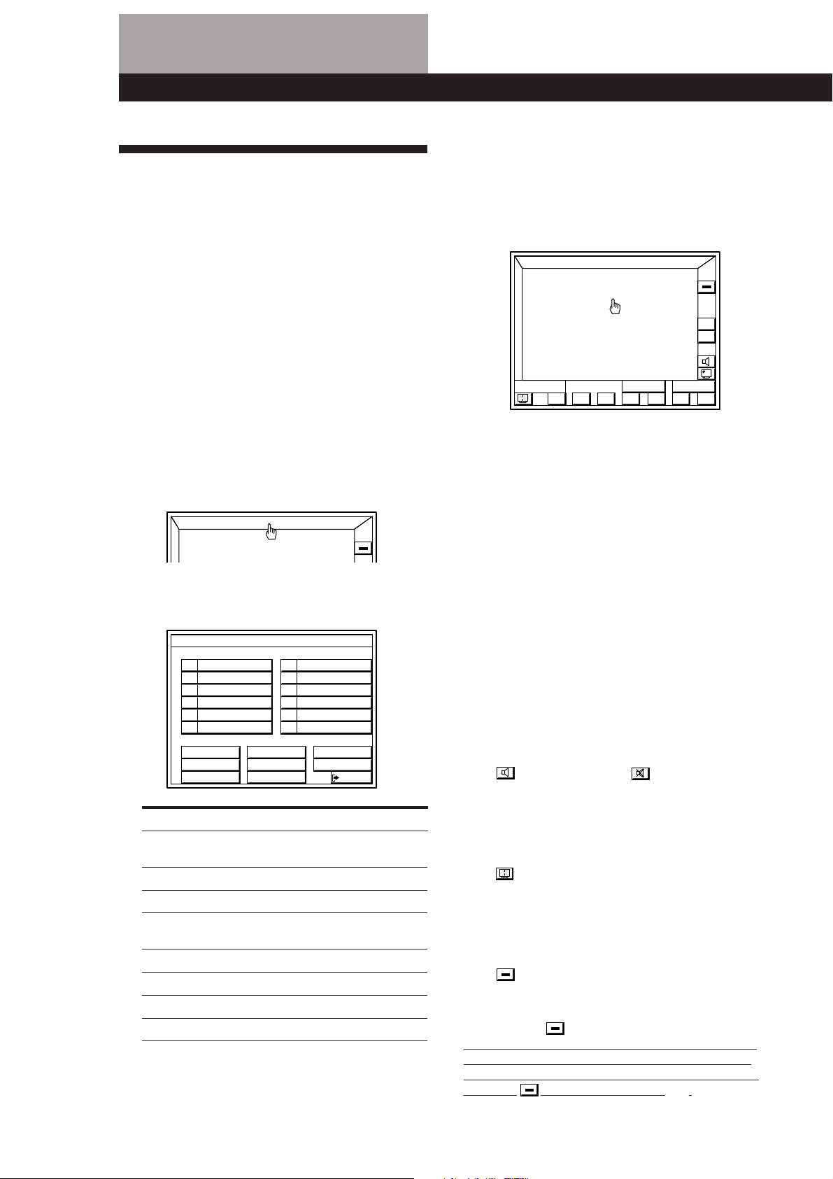
1 Pick up the remote and press the button once or
twice to turn on the receiver. Your monitor
should turn on automatically, if not see pages 17
to 18 to register your monitor.
2 Click FUNCTION in the main menu.
FUNCTION
ALL
OFF
3 Click the component you desire.
The component starts playing automatically.
4 Click VOL + or – to adjust the volume.
To adjust the volume of the TV's speakers, use the
volume control on the TV.
FUNCTION
S
O
U
N
D
)(0pP=+
Control buttons
To operate the selected component
The control buttons at the bottom of the screen function as a
remote control for the selected component. Click the button
representing the operation you desire. Refer to the manual
supplied with the component you are controlling for details
regarding its operation.
To show other control buttons for the selected
component
Click SUB.
ALL
OFF
VOL
+
–
USERSUB
24
EN
FUNCTION SELECT
VIDEO 1 DAT/MD
VIDEO 2
VIDEO 3
L D
MACRO 1
CD
TUNER
PHONO
TAPETV / DBS
MACRO 2
EXIT
To listen to or watch Click
Video tapes VIDEO 1, VIDEO 2
Laser discs LD
TV programs TV/DBS
Digital Audio Tapes (DAT) DAT/MD
or MiniDiscs (MD)
Compact Discs (CD) CD
Radio programs TUNER
Records PHONO*
Analog audio cassettes TAPE*
*1Control buttons do not appear when you select
phono.
*2The tape icon turns green during tape monitoring.
or VIDEO 3
1
2
To execute IR commands programed from other remotes
1 Click USER
2 Click A B C D repeatedly to display the command you
desire.
3 Click the button for the respective command.
To program IR codes from other remotes, see page 22.
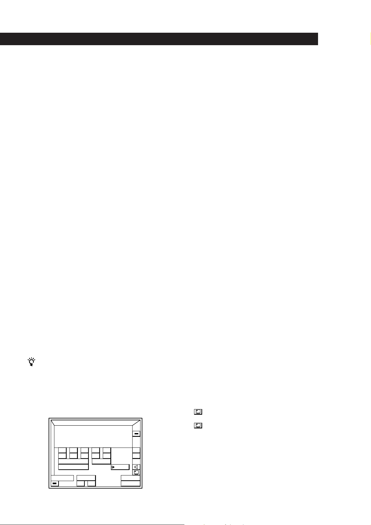
To mute the sound
Click . The icon changes to and turns green.
“MUTE ON” then “MUTING” appear in the display on the
receiver. To turn the sound back on, click on the icon again.
To turn off the MONITOR when listening to an audio
source
Click in the bottom left corner. See “Remote Operation
of Audio Sources Without the TV (illuminated control
flasher)” on page 40 for details regarding remote operation
without the TV.
To turn off the selected component
Click in the bottom left corner.
To turn off all connected components
Click ALL OFF .
If you have components that turn on only when you press
the play button, they will not turn off you click ALL OFF
when the AUTO PLAY function (see page 41) is off. In this
case, click then on the play button (().
Page 25
Basic Operations
Notes
• The AUTO PLAY function is set at the factory to start
playing the component immediately after it is selected. To
turn AUTO PLAY off, see page 41.
• Components of the same type will be controlled
simultaneously by the on-screen controls.
For example, if you use the on-screen controls to start
playing one of two Sony laser disc players in the room, the
other will also start playing at the same time.
• If a component does not respond, it may be because IR
codes from the IR repeater are not fully reaching the
selected component source. If this happens, change the
position of the IR repeater or program source.
Watching TV or Video programs
When you watch TV or video programs, we
recommend you play audio portion through the
receiver instead of your TV’s speaker. This lets you
take advantage of the receiver’s surround sound
effects, like Dolby Surround, and lets you use the
receiver’s remote to control the audio.
Turn off the speakers on your TV before you start so
you can enjoy the surround sound from your receiver.
Watching TV programs
You can use the TV tuner built in to your video deck to
watch TV programs using the receiver’s on-screen
operations.
1 Select the appropriate function (e.g. “VIDEO 2”).
2 Click TVb in the VCR controls at the bottom of the screen.
The control panels switches to the video decks’s TV
controls.
3 Click CH – or + to change the program.
To return to the VCR controls, click VTRb.
We recommend switching to the VCR controls before
switching functions. If you leave directly from the TV
controls to the FUNCTION SELECT menu, the AUTO PLAY
(page 41) function will not operate the next time you select
the video deck as a program source.
To select TV station directly when watching TV
programs using the built-in tuner on your VCR
Click SUB in the video deck control panel to display the
direct selection controls.
For Australian, Malaysian, and Singaporean models:
When using a non-Sony VCR, be sure to program -/-- or
1- and 2- codes manually as shown on page 20.
These codes are not pre-programmed in this unit.
S
O
U
N
D
6 7 8 9
– / – – 1 – 2 –
REC EDIT
FUNCTION
5 4 3 2 1
0
EXIT
ALL
OFF
VOL
+
–
Watching TV programs using a Sony TV (with TV OUT jacks)
When connecting a Sony TV with TV OUT jacks, connect the
TV OUT jacks to this unit’s TV/DBS IN jacks, then set the
TV/DBS function to “Sony TV”. This lets you watch TV
programs by selecting the TV/DBS function. Also, use the
TV’s VIDEO LABEL function to set the video input jack (e.g.,
VIDEO 1 IN) connected to this unit’s MONITOR OUT jack to
“RECEIVER”. If your Sony TV does not have TV OUT jacks,
refer to “Watching TV programs” above and use the TV
tuner built in to your video deck to watch TV programs.
Controlling a Sony DBS receiver
Before you can control the DBS receiver, the IR codes for the
function representing the DBS receiver must be set to “Sony
DBS”. The TV function is factory set to Sony DBS (to set a
different function to Sony DBS see page 19).
1 Select the appropriate function (e.g. TV)
2 Click TV /.
3 Click CURSOR MENU.
The DBS receiver control panel appears.
The icons in the cursor menu have the same function as
those on the DBS receiver (except for SELECT, which
substitutes for the enter button). Click the boarders at the
edge of the screen to move the DBS cursor.
To jump between the current and the previous channels,
click JUMP.
Controlling StarSight functions of a Sony VCR
Before you can control StarSight functions, the IR codes for
the function representing the StarSight tuner must be set to
“Sony VTR 3”. The VIDEO 1 function comes factory set to
“Sony VTR 3” (to set a different function to Sony VTR 3 see
page 19).
1 Select the appropriate function (e.g. “VIDEO 1”)
2 Click TV /.
3 Click STAR /.
The StarSight control panel appears.
Click the boarders at the edge of the screen to move the
StarSight cursor.
To change the video input of a Sony VCR
Click the INPUT icon in the video deck control panel.
Likewise, to watch a TV program after watching a video
tape, stop the VCR, click INPUT, then use the on-screen
controls to select the station you desire.
To switch the screen size when using a wide TV monitor
For Australian, Malaysian, and Singaporean models:
Click repeatedly to select the screen size you desire.
For other models:
Click to display the WIDE TV DISPLAY control panel,
then click the button for the display mode you desire.
This operation is only possible when “TV SIZE” in the TV
MONITOR SET menu is set to WIDE (see page 17).
(continued)
CH
INPUT
–
USER
/
+
VCR
25
EN
Page 26
Basic Operations
Selecting a Component Using the Controls
on the Front Panel
1
Press POWER to turn on the receiver.
Tuning and Presetting Radio
Stations
2 Press the button for the component you want to
use:
To listen to or watch Press
Video tapes VIDEO 1, VIDEO 2
or VIDEO 3
Laser discs LD
TV programs TV/DBS
Digital Audio Tapes (DAT) DAT/MD
or MiniDiscs (MD)
Analog audio cassettes TAPE MONITOR
Compact Discs (CD) CD
Radio programs TUNER
Records PHONO
3 Turn on the component, for example, a CD player,
and start playback.
When you listen with headphones
Connect the headphones to the PHONES jack and set
the SPEAKERS selector to OFF.
This receiver lets you tune and preset radio stations
from the on-screen display. You can store up to 30 FM
or AM stations, and recall them later with a simple
click. To assign names to the preset stations, see page
35.
Before you begin, make sure you have:
• Connected the RC antenna securely and correctly as
indicated on page 9 (STR-DE905G only).
• Connected an FM/AM antennas to the receiver as
indicated on page 10.
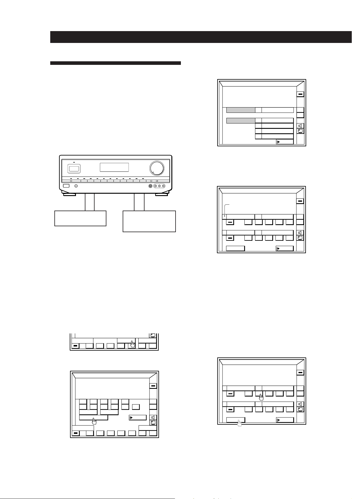
1 Click FUNCTION in the main menu.
2 Click TUNER .
3 Click BAND to select FM or AM.
FUNCTION
S
O
U
N
D
ALL
OFF
VOL
+
–
BAND
LIST
FM 102.50MHz
STEREO
USERSUB
+–
4 Click SUB, then click on TUNE MODE
MANUAL/ AUTO to select the tuning mode.
Select MANUAL for manual station selection.
Select AUTO for automatic station selection.
FUNCTION
S
A B C
O
U
N
D
6 7 8 9 10
TUNE MODE
LIST
BAND
FM 102.50MHz
5 4 3 2 1
MANUAL
SUB
STEREO
AUTO
EXIT
USER
ALL
OFF
VOL
+
–
+–
5 Click the + or – icon next to the frequency to tune
in a station.
BAND
FM 102.50MHz
SUB
STEREO
USERLIST
+–
26
EN
Page 27
Click LIST to display the memory list.
FM
00MH
9
FM
00MHz
6
Basic Operations
Tuning preset stations (preset tuning)
BAND
FM 102.50MHz
SUB
STEREO
USERLIST
+–
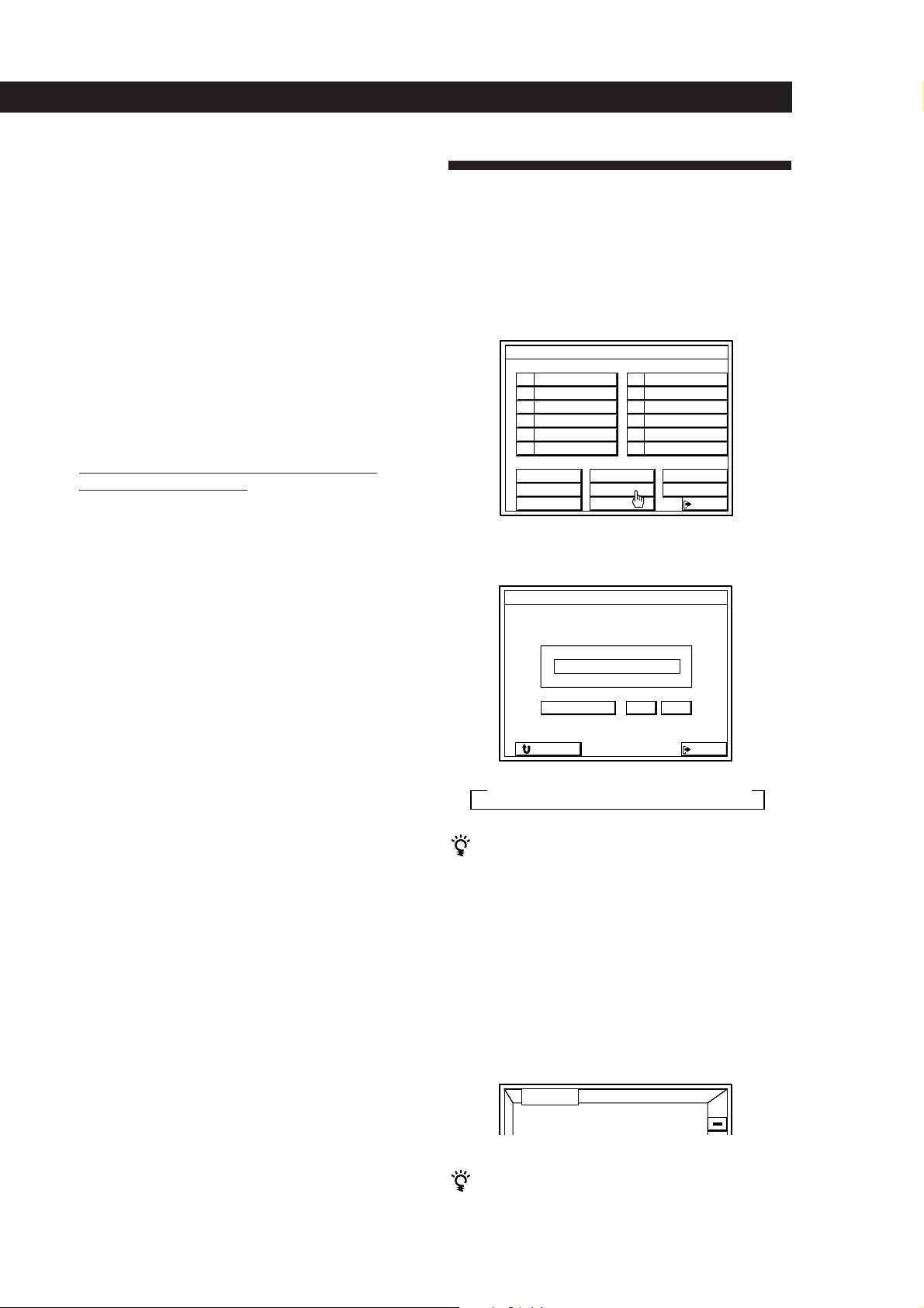
7 Click A B C repeatedly to select the page (A, B, or
C) where you want to store the station.
96.
9
FM 95.50MHz
0
ABC MEMORY
BAND
z
FM 102.50MHz
STEREO
EXIT
+–
8 Click MEMORY.
MEMORY turns red.
96.
FM 95.50MHz
0
ABC MEMORY
BAND
FM 102.50MHz
STEREO
EXIT
+–
9 Click the button (0 to 9) where you want to store
the station.
The button lights up and the station is stored.
1
FM 102.50MHz
FM 92.00MHz
2
FM 94.50MHz
3
FM 92.00MHz
4
FM 89.50MHz
5
FM 89.50MHz
6
FM 104.50MHz
7
FM 101.00MHz
8
FM 96.00MHz
9
FM 95.50MHz
0
ABC MEMORY
BAND
FM 102.50MHz
STEREO
EXIT
ALL
OFF
VOL
+
–
+–
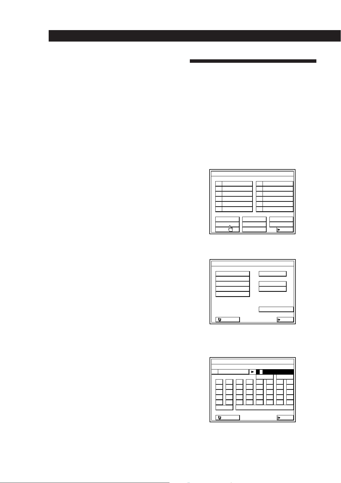
1 Click FUNCTION in the main menu.
2 Click TUNER .
3 Click LIST.
4 Click A B C repeatedly to display the station you
want.
5 Click the button (0 to 9) for the respective station.
To recall preset stations from the SUB menu
1 Click SUB.
2 Click A B C repeatedly to select the memory page.
3 Click the number of the station you want.
Tuning preset stations using the controls
on the front panel
1 Press POWER to turn on the receiver.
2 Press TUNER to select “TUNER”.
The last received station is tuned in.
3 Press PRESET TUNING +/– to tune in the preset
station you desire.
10 Repeat steps 4 through 10 to preset up to 30
stations.
During automatic tuning
When you tune past either end of the band, the
receiver automatically jumps to the opposite end and
continues scanning in the same direction. Every time a
station is received, the receiver stops scanning. To
continue scanning, press the icon again.
To change a preset station
Preset a new station at the number you want to change.
Note
If the AC power cord is disconnected for about one week,
the preset stations will be cleared from the receiver’s
memory, and you will have to preset the stations again.
To watch FM simulcast TV programs
Make sure that you tune in the simulcast program on
both the TV (or VCR) and the receiver.
EN
27
Page 28
Basic Operations
Recording
5 Click the component you want to record to
(“VIDEO 1” for example).
This receiver makes it easy to record to and from the
components connected to the receiver. You don’t have
to connect playback and recording components
directly: once you select a program source on the
receiver, you can record and edit from the on-screen
display as you normally would using the controls on
each component.
Before you begin, make sure you’ve connected all
components properly.
c
ç
c
ç
Playback component
(program source)
Recording component
(tape deck, DAT deck,
MD deck, VCR)
ç: Audio signal flow
c: Video signal flow
You can record on a cassette tape, Digital Audio Tape,
MiniDisc, or video tape (etc.) using the receiver. See the
instruction manual of your recording component if
you need help.
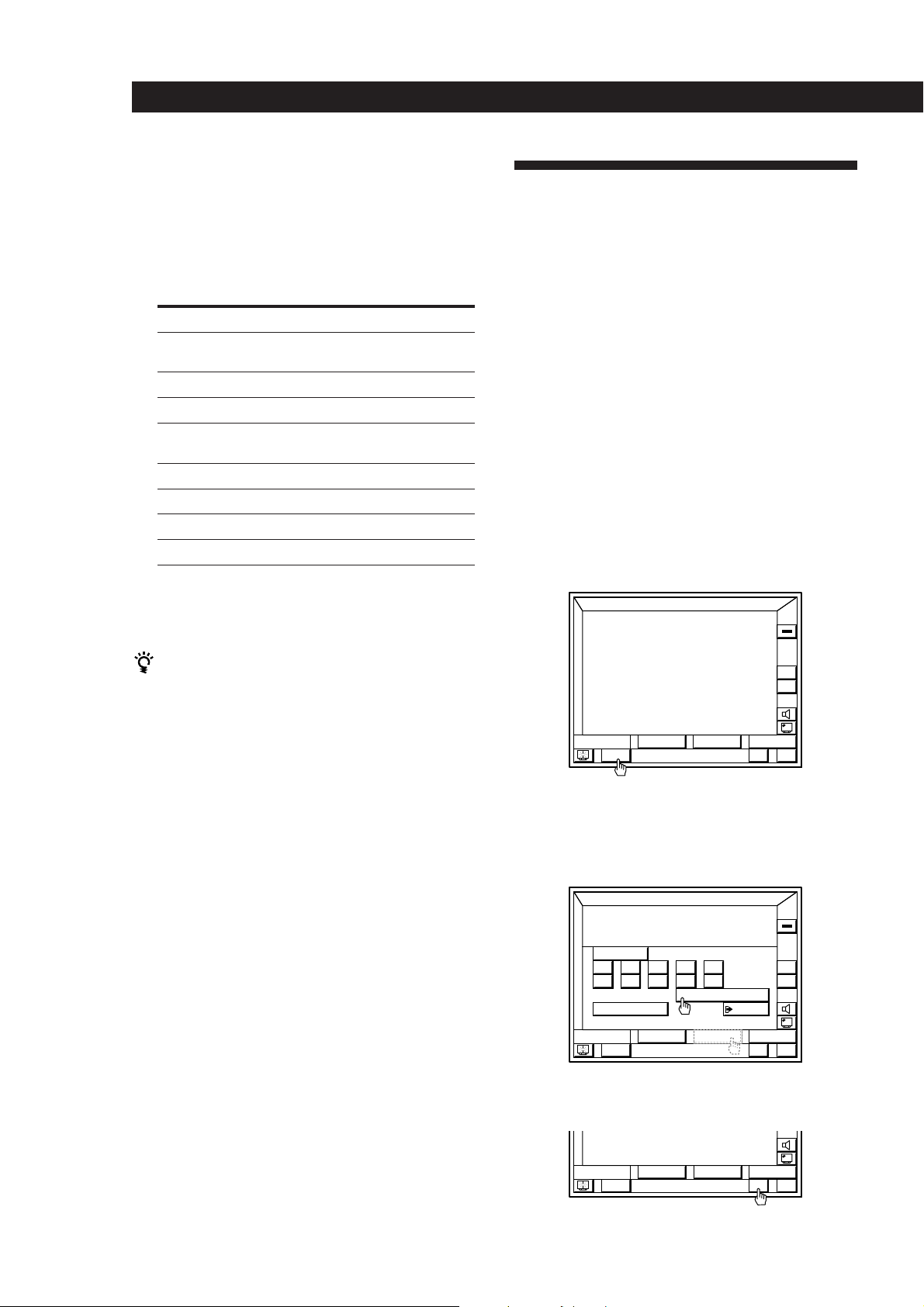
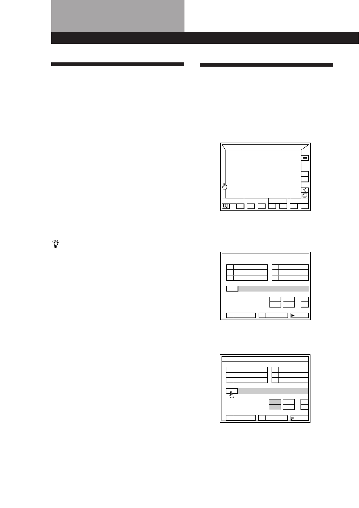
1 Click FUNCTION in the main menu.
S
O
U
N
D
PLAYER
RECORDER
FUNCTION
VIDEO 1
VIDEO 2
DAT / MD
TAPE
EXIT
ALL
OFF
VOL
+
–
The control panels for both components appear
on the TV screen. “PLAYER” for the program
source, and “RECORDER” for the program
destination.
S
O
U
b
N
D
FUNCTION
green arrow
PLAYER
RECORDER
REC
L D
(+=pP
VIDEO 1
()0pP
EXIT
ALL
OFF
VOL
+
–
The green arrow indicates the source component.
When recording, the green arrow should be next
to “PLAYER”.
Clicking a RECORDER control while recording
cuts off the program source (PLAYER).
28
EN
2 Click the program source you want to record
(“LD” for example).
3 Click on SUB.
)(0pP=+
USERSUB
4 Click REC EDIT.
S
O
U
N
D
6 7 8 9
SIDE
A
REC EDIT
FUNCTION
5 4 3 2 1
10/0
SIDE
)(0pP=+
+10
B
EXIT
USER
ALL
OFF
VOL
+
–
6 Insert a blank tape into the recording component
(or VCR, etc.) and adjust the recording level, if
necessary.
7 Click the REC to start recording, then click the
PLAYER ( control.
Recording begins.
FUNCTION
S
O
U
N
D
b
PLAYER
RECORDER
REC
L D
(+=pP
VIDEO 1
()0pP
EXIT
To control the recorder (when not recording)
Click RECORDER. “RECORDER” becomes the source
component and you can use the RECORDER controls to
rewind and playback the recording (etc.).
Click PLAYER to return control to the original source
component.
ALL
OFF
VOL
+
–
Page 29
To monitor the recorded sound when recording to a 3head cassette deck
1 Click EXIT.
2 Click FUNCTION in the main menu.
3 Click TAPE.
Basic Operations
Using the Sleep Timer
You can set the receiver to turn off automatically at a
time you specify.
To stop recording
Click on p of the recording unit.
To return to the main menu.
Click EXIT.
Notes
• There is no sound output from the recording component
even though all the buttons on the recording unit’s control
panel are operational.
• If you click RECORDER during recording, the source
being recorded will be cut off.
• If you leave the REC EDIT menu by clicking FUNCTION,
SOUND, or EXIT, recording continues, but control returns
to the PLAYER side, even if you previously clicked
RECORDER.
• If you open the FUNCTION SELECT menu and click
another program source while recording, the newly
selected program source will be recorded.
• Some cassette decks require that you press the r REC and
( buttons simultaneously to start recording. To perform
one-button from the on-screen display, be sure to record
the recording signal as shown in steps 1 to 7 of
“Registering non-Sony audio/video equipment” (pages 19
to 22) for both Sony and non-Sony products.
• Sound input through the TAPE connectors on the rear
panel cannot be recorded on a recording unit.
• When you record on a DAT or MD connected to the DAT/
MD REC OUT jacks, sound adjustments do not effect the
recording.
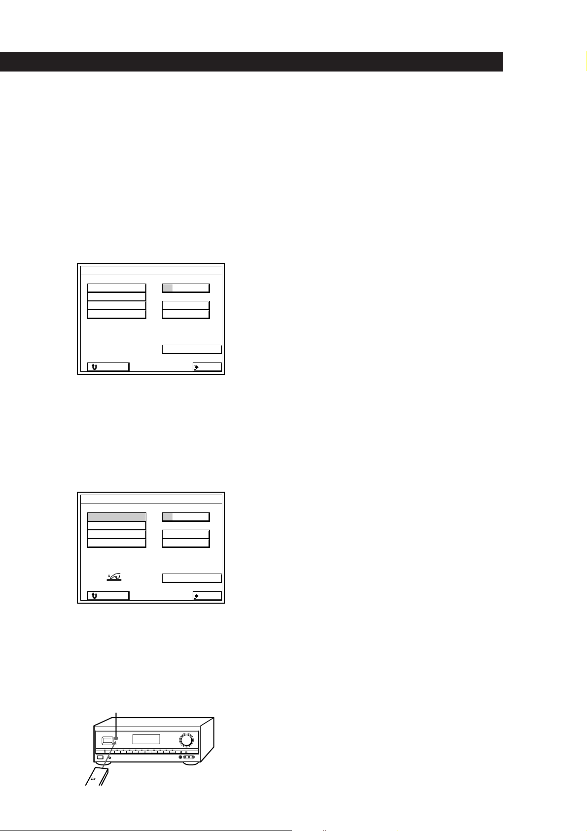
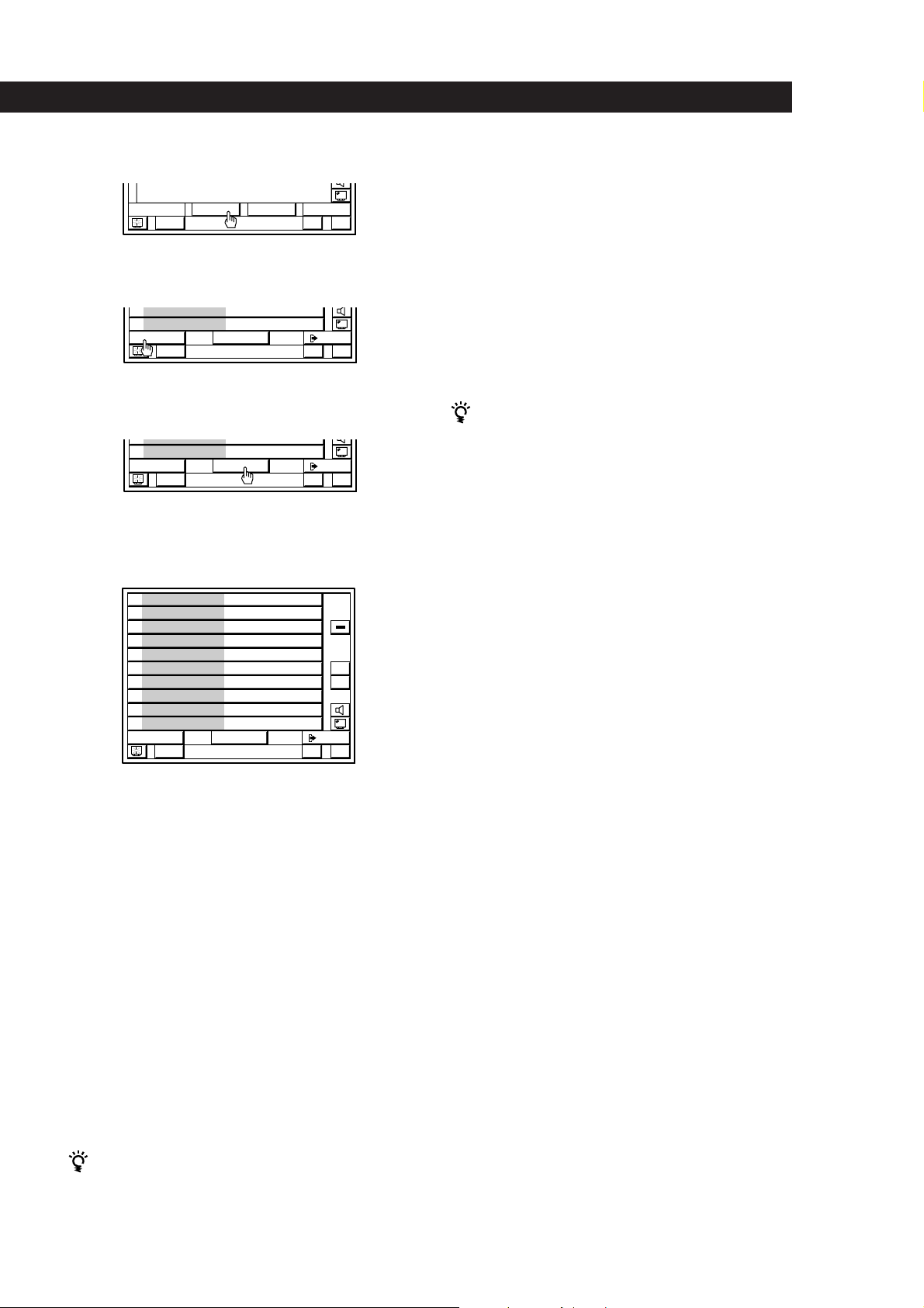
1 Click FUNCTION in the main menu.
2 Click SLEEP.
FUNCTION SELECT
VIDEO 1 DAT/MD
VIDEO 2
VIDEO 3
L D
MACRO 1
SLEEP
CD
TUNER
PHONO
TAPETV / DBS
MACRO 2
EXIT
3 Click TIMER repeatedly to select the length of the
sleep timer. The timer changes as shown below:
SLEEP TIMER SETTING
HOUR
SLEEP
RETURN
n 2:00:00 n 1:30:00n 1:00:00 n 0:30:00 n OFF
20000::
MIN SEC
–
+
EXIT
You can also freely specify the time
Click + or – to change the sleep time in 1 minute
intervals. You can specify up to 5 hours.
To return to the main menu
Click EXIT.
To go to the previous menu
Click RETURN.
When the sleep timer is set
“SLEEP” appears in the upper left corner of the main menu.
SLEEP
FUNCTION
ALL
OFF
You can check the time remaining before the
receiver turns off
Click FUNCTION, then click SLEEP. The remaining
time appears in the on-screen display.
29
EN
Page 30
Using Surround Sound
Using Surround Sound
Introduction
The STR-DE905G and STR-DE805G are provided with
a variety of surround features which allow you to
listen to a wide range sources in surround sound.
Additionally, adjustable parameters to let you
customize the sound to your preference.
To use a pre-programmed sound field
See “Using Pre-programmed Sound Fields” on this
page. This section describes how to recall the sound
fields and provides a description of each sound field.
To take advantage of Dolby Pro Logic
Surround sound
See “Getting the Most Out of Dolby Pro Logic
Surround Sound” on page 32. This section describes
how to adjust the levels of your speaker system and
customize the PRO LOGIC sound fields.
You can find Dolby Surround-encoded software by
looking at the packaging
However, some videos and laser discs may use Dolby
Surround sound even if it's not indicated on the
package.
Using Pre-programmed Sound
Fields
You can take advantage of surround sound simply by
selecting one of the pre-programmed sound fields
according to the program you want to play.
1 While playing a program source, click SOUND in
the main menu.
FUNCTION
S
O
U
N
D
)(0pP=+
2 Click a sound field genre to select the type of
sound field you desire.
The previously selected mode turns on
automatically.
SOUND FIELD SELECT
PRO LOGIC
MOVIE
MUSIC 1
MUSIC 2
SPORTS
GAME
ALL
OFF
VOL
+
–
USERSUB
To create your own sound field
See “Customizing Sound Fields” on page 33 to adjust
the tone and surround parameters.
For additional information regarding
surround sound
See the “Glossary” on pages 49 and 50.
SOUND FIELD
BASS BOOST
VOL
+
–
EXIT
3 Click MODE repeatedly to select the mode you
desire from the respective genre.
Refer to the following chart.
SOUND FIELD SELECT
PRO LOGIC
MOVIE
MUSIC 1
MODE
SOUND FIELD
BASS BOOST
To increase the bass
Click on BASS BOOST ON.
To return to the main menu.
Click EXIT.
ON
ON
MUSIC 2
SPORTS
GAME
OFF
OFF
VOL
+
–
EXIT
30
EN
Page 31

Using Surround Sound
To play without surround effects
Select “ACOUSTIC” from MUSIC 2. The surround effects are
defeated but you can still adjust the tone (see page 33).
To turn off the sound fields
Click SOUND FIELD ON/OFF.
Sound fields for STR-DE905G and STR-DE805G
GENRE MODE To
PRO LOGIC PRO LOGIC Decode programs processed with Dolby Surround.
ENHANCED Obtain additional output from rear speakers when decoding Dolby Surround
MOVIE SMALL THEATER Add the acoustic reflections of theater to decoded Dolby Surround signals.
LARGE THEATER
MONO MOVIE Create a theater-like environment from movies with monaural soundtracks.
MUSIC 1 SMALL HALL Reproduce the acoustics of a rectangular concert hall. Ideal for soft acoustic sounds.
LARGE HALL
MUSIC 2 KARAOKE Reduce the vocal tracks of stereo music sources.
ACOUSTIC Reproduce normal 2 channel stereo with tone control (TONE).
SPORTS ARENA Reproduce the feeling of a large concert arena. Great for Rock and Roll.
STADIUM Reproduce the feeling of a large open-air stadium. Great for electric sounds.
GAME GAME Obtain maximum audio impact from video game software.
programs.
31
EN
Page 32

Using Surround Sound
Getting the Most Out of Dolby
Pro Logic Surround Sound
4 Click C MODE repeatedly until the center mode
you want is displayed. Select the center mode by
referring to the following chart.
SUR EDIT
To obtain the best possible Dolby Pro Logic Surround
sound, first select the center mode according to your
speaker system. Then, equalize the speaker levels and
adjust the delay time of the PRO LOGIC sound field.
Note that you must have at least one additional pair of
speakers and/or one center speaker to do the following
adjustments.
Selecting the center mode
The receiver offers you four center modes:
PHANTOM, 3 CHANNEL LOGIC, NORMAL, and
WIDE. Each mode is designed for a different speaker
configuration. Select the mode that best suits your
speaker system configuration.
1 Click SOUND in the main menu.
2 Click PRO LOGIC to select the pro logic sound
field.
SOUND FIELD SELECT
PRO LOGIC
RETURN
If you have
Front and rear
speakers, no
center speaker
Front and center
speakers, no rear
speaker
Front and rear
speakers, and a
small center
speaker
CENTER
REAR
Select
PHANTOM
3 CH LOGIC
(3 Channel
Logic)
NORMAL
0 dB
0 dB
+
C MODE
–
+
–
VOL
+
–
EXIT
So that
The sound of the
center channel is
output from the front
speakers.
The sound of the rear
channel is output
from the front
speakers.
The bass sound of the
center channel is
output from the front
speakers (because a
small speaker cannot
produce enough
bass).
MODE
OFF
SOUND FIELD
BASS BOOST
ON
ON
OFF
EXIT
3 Click SUR.
The Dolby Pro Logic SUR EDIT screen appears.
To select the pro logic sound field.
SOUND FIELD SELECT
PRO LOGIC
MOVIE
MUSIC 1
MODE
SOUND FIELD
BASS BOOST
SUR
ON
ON
MUSIC 2
SPORTS
GAME
OFF
OFF
EXIT
VOL
+
–
VOL
+
–
Front and rear
speakers, and a
center speaker
equivalent to your
front speakers
WIDE
For wide range
Dolby Pro Logic
Surround sound to
all speakers.
Adjusting the speaker volume
The test tone feature lets you set the volume of your
speakers to the same level. (If all of your speakers have
equal performance, you don’t have to adjust the
speaker volume.)
Using the remote lets you adjust the volume level from
your listening position.
1 Click TEST.
The tone is emitted from each speaker
sequentially. The speaker emitting the test tone is
shown in red on the TV screen.
SUR EDIT
CENTER
0 dB
+
–
TEST
32
EN
Page 33

Using Surround Sound
2 Adjust the volume levels so that you hear the test
tone from each speaker at the same volume level
when you are in your listening position:
• To adjust the volume between the front right
and front left speakers, use the BALANCE
control on the front of the receiver.
• To adjust the level of center speaker, click
CENTER + or –.
• To adjust the level of rear speakers, click REAR
+ or –.
3 Click TEST to turn off the test tone.
You can adjust all speakers at one time
Use MASTER VOLUME on the front of the receiver.
Adjusting the delay time
You can make the surround sound more effective by
delaying the output from the rear speakers (delay
time). You can adjust the delay time in 0.1 ms steps
within the range of 15 to 30 ms. For example, if you’ve
placed the rear speakers in a large room or apart from
your listening position, set the delay time shorter.
To reset the current sound field to the original
factory settings
Click STD.
Adjusting the tone
You can adjust the tone of the speakers.
Follow the procedure described in “Adjusting the
tone” below.
Customizing the Sound Fields
Each sound field is composed of an equalizer (bass,
midrange, or treble) and surround sound parameters
— variables of sound, that create the sound image. You
can customize the sound fields by adjusting the
speaker level (LEVEL) and effect (EFFECT) surround
parameters to suit your listening situation.
Once you customize the sound fields, they are stored in
memory unless the receiver is unplugged for about 1
week.
1 Start playing a program source encoded with
Dolby surround sound.
2 Click DELAY.
SUR EDIT
CENTER
0 dB
DELAY
+
–
3 Click SHORT or LONG to adjust the delay time.
SUR EDIT
DELAY
SHORT LONG
RETURN
To return to the main menu
Click EXIT.
To go to the previous menu
Click RETURN.
DELAY
VOL
+
–
EXIT
Adjusting the tone
Adjust the tone of the front, center and rear speakers
for optimum sound. You can adjust the tone of all
sounds fields, including Dolby Surround.
1 Start playing a program source, then click
SOUND in the main menu.
2 Click the genre of sound field you want to reset.
The previously selected mode turns on
automatically.
3 Click MODE repeatedly to select the mode you
want to adjust.
4 Click TONE.
The TONE EDIT menu appears.
SOUND FIELD SELECT
PRO LOGIC
MOVIE
MUSIC 1
MODE
SOUND FIELD
BASS BOOST
TONE
ON
ON
MUSIC 2
SPORTS
GAME
OFF
OFF
VOL
+
–
EXIT
(continued)
33
EN
Page 34

Using Surround Sound
5 Click BASS + or – to adjust the level of the low
frequencies and click TREBLE + or – to adjust the
level of the high frequencies as you desire.
SUR EDIT
+10 dB
+10
-10
BASS TREBLE
-10 dB
+
–
RETURN
Note
You may hear some noise as you adjust the parameters.
To start adjustment with a flat equalizer curve.
Click FLAT
To reset the tone parameter of the selected sound field
to the original factory settings
Click STD.
To exit to the main menu
Click EXIT.
FLAT
STD
VOL
+
–
+
–
EXIT
4 Click SUR.
The SUR EDIT menu appears.
To adjust the speaker levels
Click LEVEL then click + or – to adjust the
speakers to the levels you prefer.
SUR EDIT
LEVEL
+
–
REAR
RETURN
To adjust the effect level
Click EFFECT then click UP or DOWN to adjust
the presence of the sound field to the level you
prefer.
0 dB
SUR EDIT
SUR EFFECT
VOL
EXIT
EFFECT
+
–
To return to the previous menu
Click RETURN.
To adjust the volume
Click VOL + or –.
Adjusting surround sound parameters
Change the surround parameters to fit your listening
situation. You can adjust the speaker levels and the
overall presence of the sound field.
To adjust the parameters of the PRO LOGIC sound
field, see “Getting the Most Out of Dolby Pro Logic
Surround Sound” on page 32.
1 Start playing a program source, then click
SOUND in the main menu.
2 Click the genre of sound field you want to reset.
The previously selected mode turns on
automatically.
3 Click MODE repeatedly to select the mode you
want to adjust.
VOL
+
DOWN
RETURN
To reset all parameters of the current sound field to
the original factory settings.
Click STD.
To exit to the main menu
Click EXIT.
To return to the previous menu
Click RETURN.
To adjust the volume
Click VOL + or –.
Note
If you make new adjustments to a sound field, the previous
settings are replaced by the new ones.
UP
–
EXIT
34
EN
Page 35

Advanced Operations
Using the INDEX functions
Advanced Operations
6 Spell out the new name by clicking each character
in order. The name is stored automatically.
The index functions let you customize the function
menu, tuner preset list, and CD list. You can specify
the icons and names up to 8 characters long for each
function button, specify names up 8 characters long for
each preset radio station, and specify names up to 12
characters long for each compact disc (up to 200 discs)
or group of discs in a CD changer.
Changing icons and names of function
buttons
1 Click FUNCTION in the main menu.
The FUNCTION SELECT menu appears.
2 Click INDEX.
The INDEX SETTING screen appears.
FUNCTION SELECT
INDEX SETTING
bB
A
B
C
D
E
1
2
F
K
P
U
CAPS
RETURN
G
H
I
J
L
M
W
N
R
S
X
Q
V
4
O
7
T
/
Y
Z
5
8
0
–
EXIT
3
6
9
*
+
To enter a space
Click the space bar.
To switch between upper and lower case letters
Click CAPS.
If you make a mistake
Click ? or / to move the cursor to the character to be
changed, then click the correct character (or click the
space bar to erase the character).
To go back to the previous menu
Click RETURN.
To exit to the main menu.
Click EXIT.
INDEX
EXIT
3 Click the icon to be changed.
4 Click the icon you desire from the icon menu,
then click RETURN.
5 Click the function button to be changed.
INDEX SETTING
VIDEO 1
VIDEO 2
VIDEO 3
LD
TV / DBS
MACRO 1
LIST
RETURN
DAT/MD
CD
TUNER
PHONO
TAPE
MACRO 2
EXIT
Adding names to preset radio stations
Click the LIST TUNER button in the INDEX
1
SETTING screen.
INDEX SETTING
LIST
RETURN
The list of the preset frequencies appears. Click
on A, B, or C to select the page. Then click on 0 to
9 to select the station to be named.
TUNER
EXIT
(continued)
35
EN
Page 36

Advanced Operations
2 Spell out the name by clicking each character in
order. The name is stored automatically.
INDEX SETTING
A
B
C
D
F
K
P
U
CAPS
RETURN
G
H
L
M
Q
R
V
W
E
I
J
N
O
S
T
X
Y
To enter a space
Click the space bar.
To switch between upper and lower case letters
Click CAPS.
If you make a mistake
Click ? or / to move the cursor to the character to be
changed, then click the correct character (or click the
space bar to erase the character).
To go back to the previous menu
Click RETURN.
bB
1
2
5
8
0
–
EXIT
3
6
9
*
+
4
7
/
Z
2 Click the DATA LOAD button.
CD INDEX SETTING
1
2
3
4
5
6
7
8
9
10
RETURN
CD name data is downloaded and after a few
minutes, the downloaded data appears in the CD
INDEX SETTING menu.
Notes
• The DATA LOAD button will not appear if the CD
changer is not registered as a Sony CONTROL A1 CD in
the IR CODE SETTING menu (see page 20) or if the CD
changer is not turned on.
• The DATA LOAD procedure will not work if the CD
change is not turned on or if the CTRL A1 connection is
incomplete (see page 11).
• If the following characters have been recorded in the CD
changer, they will appear as blanks in the on-screen
display: # $ ; • ä ö ü
>
DATA
LOAD
.
EXIT
To exit to the main menu.
Click EXIT.
Adding names to CDs in a Sony CD changer
equipped with a CTRL A1 jack
If your CD changer is a Sony product with a CTRL A1
jack, you can download all of the CD name data in the
CD changer, thus saving you the trouble of adding
names one by one.
1 Click the LIST CD button in the INDEX SETTING
screen.
INDEX SETTING
LIST
RETURN
CD
EXIT
To go back to the previous menu
Click RETURN.
To exit to the main menu.
Click EXIT.
Adding names to CDs in non-Sony CD
changers or Sony CD changers without
CTRL A1 jacks
If your CD changer is not a Sony Product or does not
have a CTRL A jack, you will have to add names
manually as follows;
1 Click the LIST CD button in the INDEX SETTING
screen.
INDEX SETTING
36
EN
LIST
RETURN
CD
EXIT
Page 37

2
• To name a disc
Click TITLE. Display the number of the disc to
be named by clicking the > or . icon on the
right side of screen, then click the disc to be
named.
• To name a group, click GROUP.
Click GROUP, then click the group to be
named.
Advanced Operations
Operating a CD Changer
Grouping CDs
You use the on-screen display to assign your CDs to
one or more groups.
3 Spell out the name by clicking each character in
order. The name is stored automatically.
CD INDEX SETTING
vV
10
A
B
C
D
F
K
P
U
CAPS
RETURN
G
Q
V
H
L
M
R
W
E
I
J
N
O
S
T
X
Y
To enter a space
Click the space bar.
To switch between upper and lower case letters
Click CAPS.
If you make a mistake
Click ? or / to move the cursor to the character to be
changed, then click the correct character (or click the
space bar to erase the character).
To go back to the previous menu
Click RETURN.
To exit to the main menu.
Click EXIT.
bB
1
2
5
8
0
–
EXIT
3
6
9
*
+
4
7
/
Z
1 Click FUNCTION in the main menu.
The FUNCTION SELECT menu appears.
2 Click INDEX.
The INDEX SETTING screen appears.
3 Click the LIST CD button.
4 Click SELECT, then click the disc you want to
assign to a new group.
CD INDEX SETTING
BGM A
21
BGM B
22
Love Songs
23
BEST of BB
24
BEST of CC
25
BEST of DD
26
27
28
29
30
RETURN
>
DATA
SELECT
.
EXIT
If the disc you want is not displayed
Click the > or . icon to display the disc.
5 Click the names of the groups you want to assign
the CD to.
For example, to assign the CD to both “GROUP 1”
and “GROUP 4”, click both group names so that
they are highlighted.
CD INDEX SETTING
GROUP 1
1
GROUP 2
2
GROUP 3
3
GROUP 4
4
GROUP 5
5
GROUP 6
6
GROUP 7
7
GROUP 8
8
GROUP 9
9
GROUP 10
10
RETURN
EXIT
To remove the CD from one or more groups
Click the highlighted group name so that it goes out.
To go back to the previous menu
Click RETURN.
To go back to the main menu.
Click EXIT.
(continued)
37
EN
Page 38

Advanced Operations
Playing CDs with the LIST function
1
Click FUNCTION in the main menu.
The FUNCTION SELECT menu appears.
2 Click CD.
3 Click LIST.
LIST
)(0pP=+
USERSUB
4 Click the > or . icons to see the next or previous
10 discs, then click the disc. Playback starts
automatically.
When a Sony CD changer equipped with a CTRL
A1 jack is connected, the disc capacity shown on
screen changes automatically in accordance with
the capacity of the CD changer.
CD LIST - DISC NUMBER
1
2
3
4
5
6
7
8
9
10
SEARCH
=+ p
>
.
EXIT
ALL
OFF
VOL
+
–
discs are displayed in numeric order.
Click the > or . icons to display disc , then
click the disc. Playback starts automatically
Notes
• Depending on the type of CD changer connected (3 or 5
disc changer, etc), you may not be able to select the CD
even by clicking the disc name. In this case, select the CD
from the normal CD control panel.
• If the CD changer is made by another manufacturer, and
the sequence of operations required to start playback is
other than; 1 pressing a numeric button followed by 2
pressing the disc button, then playback may not start
when you click the disc name. In this case, return to the
main menu, click SUB, and operate the CD changer
according to its normal playback procedure.
Enjoying Two Components at
the Same Time
Use the procedure below to play two program sources
at the same time (for example, to play a laser disc while
listening to a compact disc).
Make sure the AUTO PLAY function is set to off (see
page 41).
38
EN
To Locate a specific disc
Click SEARCH, the CD LIST - SEARCH screen
appears.
CD LIST - SEARCH
GROUP NAME
ALPHABET
DISC NUMBER
ALL
OFF
VOL
+
–
RETURN
• To display the discs in a certain group.
Click GROUP NAME, then click the name of
the group in which the CD is located.
The CD list for that group is displayed. Click
the > or . icons to display disc , then click the
disc. Playback starts automatically
• To display the discs in alphabetical order.
Click ALPHABET, after a few seconds, discs
are displayed in alphabetical order.
Click the > or . icons to display disc , then
click the disc. Playback starts automatically
• To display the discs in numeric order.
Click DISC NUMBER, after a few seconds,
EXIT
1 Click FUNCTION in the main menu.
The FUNCTION SELECT menu appears.
2 Click a video program source.
The control panel for the video program source
appears.
Click (.
3 Click on FUNCTION again, then click an audio
program source.
The control panel for the audio program source
appears.
Click (.
To stop play
Click the p button in each control panel.
Page 39

Operating Several Components
in Sequence Automatically
(macro play)
The macro functions (1 and 2) let you link up to eight
IR command codes in sequential order for execution as
a single command. You can specify the IR codes from
both the preset and user IR code lists. The macros can
then be executed either manually (by selecting them
from the FUNCTION SELECT menu) or automatically
(by specifying them in the AUTO START SETTING
menu (see page 41)).
1 Click FUNCTION in the main menu.
The FUNCTION SELECT menu appears.
2 Click MACRO.
The MACRO PLAY SETTING menu appears.
FUNCTION SELECT
Advanced Operations
5 Click ? or / to show the IR codes available for
that button.
The IR codes recorded for the various components
in the FUNCTION SELECT menu and the IR
codes in the user IR menu set appear in groups of
5 at the right of the screen.
To specify a time lag between commands
Click ? or / repeatedly to display the time lag
commands (WAIT 10s, WAIT 5s, and WAIT 1s).
To specify an IR code to turn off all the components
Click ? or / repeatedly to display ALL OFF.
Note
If the macro was selected for automatic execution at
startup with the AUTO START function (see page 41),
ALL OFF cannot be selected in that macro.
6 Click on the IR code you desire.
The name of the IR code appears in the
highlighted macro step number and the next
macro step number is highlighted.
7 Repeat steps 5 and 6 to enter up to eight IR codes.
MACRO
EXIT
3 Click MACRO 1 or 2.
MACRO PLAY SETTING
1
2
3
4
5
6
7
8
RETURN
1 2MACRO COMMAND
WAIT 10s
WAIT 5s
WAIT 1s
ALL OFF
NO SET
EXIT
4 Click macro step number 1.
This is the first IR code in the macro sequence.
MACRO PLAY SETTING
1
2
3
4
5
6
7
8
RETURN
1 2MACRO COMMAND
NO SET
WAIT 10s
WAIT 5s
WAIT 1s
ALL OFF
NO SET
EXIT
To erase an entered IR code
1 Click the code you want to erase so it will be highlighted.
2 Click ? or / repeatedly until NO SET appears at the
right of the screen.
3 Click NO SET to erase the IR code highlighted in step 1.
To enter IR codes randomly
1 Click a numbered macro button.
2 Click ? or / repeatedly until the IR code you desire
appears at the right of the screen.
3 Click the IR code.
To execute a macro
Click FUNCTION in the main menu.
/?
1
The FUNCTION SELECT menu appears.
2 Click MACRO 1 or MACRO 2.
Execution of the specified IR codes starts
automatically.
FUNCTION SELECT
MACRO 1
/?
MACRO 2
EXIT
39
EN
Page 40

Settings and Adjustments
Settings and Adjustments
Remote Operation of Audio
Sources Without the TV
(illuminated control flasher)
The Illuminated Control Flasher (or flasher) function
allows you to control audio program sources without
using the TV’s on-screen display by using only the
remote and the front panel of the receiver.
When you move the remote (STR-DE905G) or press the
direction control button (STR-DE805G), the indicator
lamps on the front panel light up in succession. These
lamps, let you select and control the operations that
appear in the display on the receiver.
1 Click FUNCTION in the main menu.
The FUNCTION SELECT menu appears.
2 Click SET UP.
FUNCTION SELECT
6 Move the remote from left to right (STR-DE905G)
or press the left or right side of the direction
control button (STR-DE805G).
Various operations for the selected program
source appear in the display according to the
movement of the remote. The indicator
corresponding to the operation button on the
front panel also lights up.
The operations available for each program source
are shown below.
Program source Operations
DAT/MD = ( + p
CD = ( + p
TUNER PRESET– PRESET +
PHONO No display
TAPE 0 ( ) p
All sources INPUT SELECT, ALL OFF, TV ON,
VOLUME –, VOLUME +, MUTE
SET UP
EXIT
3 Click FLASHER ON.
SET UP
AUTO PLAY
FLASHER
IR OUTPUT
AUTO OSD ERASE
POINTER ONLY
DEMO
FEELING
RETURN
ON OFF
EXIT
4 Click an audio program source in the FUNCTION
SELECT menu.
5 Click the TV off icon to turn off the TV monitor.
7 Click the remote when the operation you want
appears in the display.
To select another program source
1 Click the remote when INPUT SELECT appears in
the display.
2 Move the remote commander from left to right.
The various program sources appear in the display
one at a time. If you select a video program source,
the TV set will turn on automatically.
To cancel the flasher function
Click the remote when TV ON appears in the display,
or select a video component.
Note
If you select “ALL OFF” in the flasher mode, the next
time the receiver is turned on it turns on in flasher
mode. The receiver turns on normally, however, if
there are components set to auto start (see page 41).
40
)(0pP=+
USERSUB
Note
The TV off icon for the flasher function only appears
when you select audio program sources.
EN
Page 41

Settings and Adjustments
Playing Sources Automatically
(auto play)
The AUTO PLAY function lets you set the receiver to
start playing the program sources immediately after
they are selected from the FUNCTION SELECT menu.
The receiver comes with AUTO PLAY set to ON.
1 Click FUNCTION in the main menu.
The FUNCTION SELECT menu appears.
2 Click SET UP.
3 Click AUTO PLAY ON or OFF to select auto play
on or off.
SET UP
AUTO PLAY
FLASHER
IR OUTPUT
AUTO OSD ERASE
POINTER ONLY
DEMO
FEELING
ON OFF
Starting a Source
Automatically at Power On
(auto start)
The AUTO START function lets you set the receiver to
start playing a specific program source immediately
whenever you turn on the receiver.
1 Click FUNCTION in the main menu.
The FUNCTION SELECT menu appears.
2 Click AUTO.
The AUTO START SETTING screen appears.
FUNCTION SELECT
AUTO
EXIT
RETURN
EXIT
To return to the main menu
Click EXIT.
To go to the previous menu
Click RETURN.
Notes
• If you select another component during playback, the
current component stops and the newly selected
component starts playing.
• The AUTO PLAY function does not work when you
operate the receiver using the controls on the front panel.
• The AUTO PLAY function may not work for components
with poor remote control response. If you experience this,
reposition the IR repeater closer to that component to
facilitate reception of the IR command codes.
3 Click the component you want to start playing
automatically when the receiver is turned on.
Only one program source can be selected.
To automatically start the component played last the
next time you turn on the receiver
Click LAST.
To execute a macro automatically when you turn on
the receiver
Click MACRO 1 or MACRO 2 when the AUTO PLAY
function is ON and the program source is specified in
the MACRO PLAY setting (see page 39).
When LAST is specified, the program source last played
will turn on automatically the next time you turn on the
receiver.
To cancel the AUTO START function
Click NO SET in step 3.
AUTO START will not operate when you turn on the
receiver.
To return to the main menu
Click EXIT.
To go to the previous menu
Click RETURN.
Note
Macros containing the ALL OFF command (see page 39)
cannot be selected for use with the AUTO START function.
41
EN
Page 42

Settings and Adjustments
Adjusting the Sensitivity of the
Remote
You can select from five different sensitivity levels that
determine the speed at which the pointer moves.
1 Click FUNCTION in the main menu.
The FUNCTION SELECT menu appears.
2 Click SET UP.
3 Click FEELING 1 through 5 to select the
sensitivity level you desire.
The higher the number, the faster the speed.
SET UP
AUTO PLAY
FLASHER
IR OUTPUT
AUTO OSD ERASE
POINTER ONLY
DEMO
FEELING
RETURN
To return to the main menu
Click EXIT.
1 2 3 4 5
EXIT
Selecting the Display
Parameters
Use this procedure to select one of three display
modes: AUTO OSD ERASE, POINTER ONLY, or
DEMO.
It also allows you to switch the IR OUTPUT setting
when you use the IR repeater.
1 Click FUNCTION in the main menu.
The FUNCTION SELECT menu appears.
2 Click SET UP.
3 Click AUTO OSD ERASE ON or OFF, POINTER
ONLY SET or DEMO START to select the display
mode as necessary.
If necessary, click IR OUTPUT ON or OFF.
SET UP
AUTO PLAY
FLASHER
IR OUTPUT
AUTO OSD ERASE
POINTER ONLY
DEMO
FEELING
RETURN
ON OFF
ON OFF
SET
START
EXIT
To go to the previous menu
Click RETURN.
Note (STR-DE905G only)
If you find it difficult to change the remote commander
sensitivity because the setting is too high (i.e., 5), turn off the
unit, then turn it on while holding down the CD and
PHONO buttons on the front panel.
The remote commander sensitivity will return to the factory–
set value.
AUTO OSD ERASE:
This display mode is useful during laser disc operations
since it allows you to see chapter numbers that
otherwise might be hidden by the control panel.
When this mode is on, control panels disappear
whenever you click and hold down a control button.
When you release the button, the control panel
reappears.
POINTER ONLY:
This display mode allows you to use the pointer to
point to various on screen items, such as during a
presentation (etc.).
When you click POINTER ONLY SET, the on–screen
display disappears except for the pointer and an EXIT
button. To freeze the pointer, hold down the button on
the remote.
42
EN
Page 43

DEMO:
This display mode activates a program that explains the
various functions of the receiver. Please note that when
the program is running it replaces previously stored
data (such as surround sound parameters) with data
from the program. Therefore, you should only use the
DEMO mode when no data has been stored or when
rewriting existing data does not matter.
Click START to activate the program. To stop the
program, click the button on the remote two or three
times or turn off the receiver.
Settings and Adjustments
Adjusting the Position of the
On-Screen Display
The graphic position function (GRAPHIC POSITION)
lets you make fine adjustments to the overall position
of the on-screen display control panel.
1 Click FUNCTION in the main menu.
The FUNCTION SELECT menu appears.
IR OUTPUT:
When it is set to OFF, the IR signals are only output
from the IR OUT jack on the rear panel. No IR signals
will be output from the IR repeater on the front panel.
When the IR OUTPUT is set to OFF, “IR OFF” appears
in the main menu.
Normally, IR OUTPUT should be set to ON.
To return to the main menu
Click EXIT.
To go to the previous menu
Click RETURN.
2 Click TV SET.
3 Click GRAPHIC POSITION SET.
The position adjustment screen appears.
TV MONITOR SET
TV IR SET
TV INPUT
GRAPHIC POSITION
RETURN
The position adjustment screen appears.
B
VIDEO
SET
V
EXIT
b
v
EXIT
Click the boarders to adjust the position so you
can just see the top, bottom, right and left edges of
the boarder.
4 Click EXIT.
To return to the main menu
Click EXIT.
To go to the previous menu
Click RETURN.
43
EN
Page 44

Additional Information
Front Panel Descriptions
1
2
1 POWER switch
2 Infrared (IR) repeater
Emits IR codes to command
program sources.
3 Infrared (IR) codes setting
indicator
Lights up when the unit receives
IR codes.
4 IR sensor
When recording IR codes from
the remote controls of other
components, point the remote’s
emitter at this area during
operation.
5 Display
Shows the program source,
function, and tuning frequency,
etc.
6 MASTER VOLUME control
Adjusts the overall sound
volume.
43
!•!ª
!§!¶
7 SOUND FIELD button
Turns the sound field on and off.
8 VIDEO 3 INPUT jacks
For connecting camcorders or
video game units, etc.
9 PRESET TUNING +/–
Selects preset stations.
0 PHONO button
Selects the record player
connected to the PHONO jacks.
!¡ TUNER button
Selects the tuner.
!™ CD button
Selects the compact disc player
connected to the CD jacks.
!£ DAT/MD button
Selects the DAT or MiniDisc
deck connected to the DAT/MD
jacks.
5
!∞ !¢
!¡
0
!™
!£ 7
6
8
9
!¢ TV/DBS button
Selects the DBS receiver
connected to the DBS jacks.
!∞ LD (Laser Disc) button
Selects the lase disc player
connected to the LD jacks.
!§ VIDEO 1-3 buttons
Selects the video components
connected to the VIDEO 1-3
jacks.
!¶ TAPE MONITOR button
For monitoring audio program
sources during recording.
!• PHONES jack
For connecting stereo
headphones.
!ª SPEAKERS selector
For turning the speakers OFF or
ON.
44
EN
Page 45

Rear Panel Descriptions
Additional Information
1234 6578 9
@¡@™
1 CNTRL-A1
2 IR OUT
3 RC ANT (STR-DE905G only)
4 MONITOR
5 TV/DBS
6 LD
7 VIDEO 2
8 VIDEO 1
9 MIX AUDIO OUT
@º
!•
!ª
!¶
0 FRONT SPEAKERS
!¡ IMPEDANCE SELECTOR
(See page 12)
!™ VOLTAGE SELECTOR
(certain models only)
!£ AC power cord
!¢ SWITCHED AC OUTLETs
(Outlet shape and position varies
according to destination)
0
!§
!¡
!™
!£
!¢!∞
!∞ CENTER SPEAKER
!§ REAR SPEAKERS
!¶ TAPE
!• DAT/MD
!ª CD
@º PHONO
@¡ ANTENNA (AM/FM)
@™ y SIGNAL GND terminal
45
EN
Page 46

Additional Information
Troubleshooting
If you experience any of the following difficulties while
using the receiver, use this troubleshooting guide to
help you remedy the problem. Should any problem
persist, consult your nearest Sony dealer.
The TV set turns off when you turn on the receiver with
the remote.
/ Make sure that the TV set is off when you
turn on the receiver with the remote.
Severe hum or noise is heard.
/ Check that the speakers and components are
connected securely.
/ Check that the connecting cords are away
from a transformer or motor, and at least 3
meters away from a TV set or fluorescent
light.
/ Place your TV away from the audio
components.
/ Make sure you connect a ground wire to the
antenna ground terminal.
/ The plugs and jacks are dirty. Wipe them
with a cloth slightly moistened with alcohol.
When you select a program source from the FUNCTION
SELECT menu, the selected program source turns off.
/ The program source was turned on by a
different remote. The program source needs
to be turned on by the receiver or manually.
Some equipment does not turn off when you click on the
ALL OFF button.
/ The equipment was turned on by another
remote commander. Turn off the equipment
manually.
There’s no sound or only a very low-level sound is heard.
/ Check that the speakers and components are
connected securely.
/ Make sure you selected the correct
component.
/ Make sure you set the SPEAKERS selector to
ON.
/ Click the
the display.
/ The protective device on the receiver has been
activated because of a short circuit.
(“PROTECTOR” flashes.) Turn off the
receiver, eliminate the short-circuit problem
and turn on the power again.
The left and right sounds are unbalanced or reversed.
/ Check that the speakers and components are
connected correctly and securely.
/ Adjust the BALANCE control.
icon if “MUTING” appears in
No sound is heard from the center speaker.
/ Select a PRO LOGIC or MOVIE (except Mono
movie) sound field (see pages 30 and 31).
/ Select the appropriate center mode
(see page 32).
/ Adjust the speaker volume appropriately
(see page 32).
Recording cannot be made.
/ Check that the components are connected
correctly.
/ Select the source component from the
FUNCTION SELECT menu or with the
function buttons.
No sound or only a very low-level sound is heard from
the rear speakers.
/ Turn on the sound field function.
/ Select the appropriate center mode
(see page 32).
/ Adjust the speaker volume appropriately
(see page 32).
/ Make sure you turned on the sound field
function.
Radio stations cannot be tuned in.
/ Check that the antennas are connected
securely. Adjust the antennas and connect an
external antenna if necessary.
/ The signal strength of the stations is too weak
(when you tune in with automatic tuning).
Use direct tuning.
/ Make sure you set the tuning interval
correctly (when you tune in AM stations with
automatic tuning) (see page 48).
/ No stations have been preset or the preset
stations have been cleared (when you tune in
with scanning preset stations). Preset the
stations (see page 26).
46
EN
Page 47

Additional Information
Surround effect cannot be obtained.
/ Turn on the sound field function.
/ Make sure that the SPEAKERS selector is set
to ON.
No picture or an unclear picture is seen on the TV screen.
/ Select the appropriate function on the
receiver.
/ Set your TV to the appropriate input mode.
/ Place your TV away from the audio
components.
The on-screen display disappears while you are using the
commander (STR-DE905G only).
/ Check that the RC antenna is connected
securely and properly.
/ Make sure there are no metal objects near the
RC antenna.
/ Make sure the remote is not too far from the
RC antenna.
You have difficulty operating the unit because the onscreen display is distorted.
/ Make sure that video components are not
connected to both the S-VIDEO and VIDEO
jacks at the same time. Use only the S-VIDEO
connectors, or the VIDEO connectors (if there
are no S-VIDEO connectors on the TV).
/ When connect two or more VCRs to the unit,
make sure to use a distributor when
connecting the TV antenna to the VCRs to
preserve video signal quality.
/ Clean the head of the VCR.
/ Do not select channels where there is no
broadcast. Set the unit to skip channels where
there is no broadcast.
The remote does not function.
/ Replace both batteries in the remote with new
ones if they are weak.
/ Connect the RC antenna to the RC ANT jack
on the rear of the receiver (STR-DE905G only)
(see page 9).
/ Remove the obstacles in the path of the
remote and the receiver (STR-DE805G only).
/ Remove the obstacles in the path of the
remote and the RC antenna (STR-DE905G
only).
/ Make sure both the remote and receiver are
set to the same security number (STR-DE905G
only) (see page 15).
IR codes of non-Sony equipment cannot be recorded.
/ Be sure that the respective remote is pointed
directly at the infrared sensor on the front of
the receiver from a distance of less than 20
cm.
/ There may be interference from a fluorescent
light source. Keep the infrared sensor away
from fluorescent light.
Note
If the unit does not operate properly even after attempting
the prescribed remedies or other problems occur, try the
following:
(1) Turn off the power, turn it on again. If the unit still does
not work, (2) turn off the power with the POWER switch,
then reinsert the plug into the power outlet and turn the
power on again. If the unit still does not work, (3) turn off
the power with the POWER switch, then turn it on while
holding down TAPE MONITOR and VIDEO 2 on the front
panel. Please note, however, that this remedy will erase all
data recorded in the unit.
The on-screen display becomes distorted when you select
a program source from the FUNCTION SELECT menu.
/ There may be distortion in the video signal,
but this is not a malfunction, continue as is.
The pointer on the on-screen display moves even when
the remote is stationary (STR-DE905G only).
/ The remote may be out of calibration. Rest the
remote on a flat surface, then try using it
again after the on-screen display disappears.
Note (STR-DE805G only)
When the receiver is placed in an audio rack (etc.) with a
glass front, the pointer may click the on-screen button
repeatedly, instead of holding it down, even though you are
holding down the button on the remote control (e.g., during
forward search while playing a video, etc.). This
phenomenon is a result of interference between the IR
repeater and receptor on the front panel. It is not a
malfunction. If this occurs, try connecting the supplied IR
repeater and placing it in an appropriate position.
47
EN
Page 48

Additional Information
Specifications
Audio power specifications
Amplifier section
POWER OUTPUT
Stereo mode
Surround mode
Output
Front
Center
Rear
Dynamic power
output
Harmonic
distortion at
rated output
Frequency
response
Inputs
Sensitivity
PHONO
(MM)
CD
TAPE,
DAT/MD,
VIDEO 1,
2, 3, TV/
DBS, LD
Singaporean and
Malaysian models
4 ohms 1 kHz DIN
100 W + 100 W
Other models
8 ohms 20 Hz - 20 kHz,
120 W + 120 W
8 ohms at 1 kHz,
THD 0.8 %
Singaporean and
Malaysian models
100 W/ch
100 W
40 W/ch
(Except for Singaporean
and Malaysian models)
160 W + 160 W, 8 ohms
225 W + 225 W, 4 ohms
Less than 0.3 %
PHONO: RIAA
equalization curve
±0.5 dB
CD, TAPE, DAT/MD,
TV/DBS, LD, VIDEO
1, 2: 10 Hz-50 kHz dB
(Direct Pass)
Impedance
2.5 mV
50
kilohms
200 mV
150 mV
50
kilohms
Other
models
120 W/ch
120 W
50 W/ch
+0
–1
S/N
(weighting
network,
input level)
75 dB**
(A, 2.5 mV)
82 dB**
(A, 250 mV)
** ‘78 IHF
Outputs
BASS BOOST
TONE
FM tuner section
Tuning range
Antenna
terminals
Sensitivity
Usable sensitivity
S/N
Harmonic
distortion at
1 kHz
Separation
Frequency
response
Selectivity
AM tuner section
Tuning range
Antenna
Usable sensitivity
S/N
Harmonic
distortion
Selectivity
REC OUT VIDEO 1, 2
(AUDIO) OUT:
Voltage 250 mV,
Impedance 10 kilohms
WOOFER OUT
Voltage: 2 V
Impedance: 1 kilohms
PHONES: Accepts low
and high impedance
headphones
+10 dB at 70 Hz
±8 dB at 100 Hz
and 10 kHz
87.5 - 108.0 MHz
75 ohms, unbalanced
Mono: 18.3 dBf, 4.5 µV
Stereo: 38.3 dBf, 45 µV
11.2 dBf, 2 µV (IHF)
Mono: 76 dB
Stereo: 70 dB
Mono: 0.3 %
Stereo: 0.5 %
45 dB at 1 kHz
30 Hz - 15 kHz dB
60 dB at 400 kHz
Australian, Singaporean,
and Malaysian models
531 - 1602 kHz
(9 kHz interval)
Other models
531 - 1602 kHz
(9 kHz interval)
530 - 1610 kHz
(10 kHz interval)*
Loop antenna
50 dB/m (at 1,000 kHz or
999 kHz)
54 dB (at 50 mV/m)
0.5 % (50 mV/m,
400 kHz)
At 9 kHz: 35 dB
At 10 kHz: 40 dB
+0.5
–2
* You can change the AM tuning interval
between 9 kHz and 10 kHz. After tuning
in any AM station, turn off the receiver.
Hold down the PRESET + button and
press the POWER button. All preset
stations will be erased when you change
the interval. To reset the interval, repeat
the procedure.
(Except for Australian, Singaporean, and
Malaysian models)
Video section
Inputs
Outputs
VIDEO 1, 2, 3, LD,
TV/DBS:
1 Vp-p 75 ohms
VIDEO 1, 2, MONITOR:
1 Vp-p 75 ohms
General
System
Power
requirements
Power
consumption
AC outlets
Dimensions
Mass (Approx.)
Supplied
accessories
Design and specifications are subject to
change without notice.
Tuner section: PLL
quartz-locked digital
synthesizer system
Preamplifier section:
Low-noise NF type
equalizer
Power amplifier section:
Pure-complimentary
SEPP
Australian, Singaporean,
and Malaysian models:
240 V AC, 50/60 Hz
Other models:
120/220/240 V AC,
50/60 Hz
Singaporean and
Malaysian models:
275 W
Other models:
270 W
Australian and
Singaporean models:
1 switched, 100 W
Other models:
1 switched, 120 W
430 x 160 x 365 mm
10.0 kg
FM wire antenna (1)
AM loop antenna (1)
Remote commander
(remote) (1)
Size AA (R6) batteries (2)
RC antenna
(STR-DE905G only) (1)
IR repeater (1)
Getting Started and Basic
Operation Guide (1)
48
EN
Page 49

Additional Information
Glossary
Center mode
Setting of speakers to enhance Dolby Pro
Logic Surround mode. To obtain the best
possible surround sound, select one of the
following four center modes according to
your speaker system.
• NORMAL mode
Select NORMAL mode if you have front
and rear speakers and a small center
speaker. Since a small speaker cannot
produce enough bass, the bass sound of
the center channel is output from the front
speakers.
Front
speaker (L)
speaker (L)
Center
speaker
Rear
• WIDE mode
Select WIDE mode if you have front and
rear speakers and a large center speaker.
With the WIDE mode, you can take full
advantage of Dolby Surround sound.
Front
speaker (L)
Center
speaker
Rear
speaker (L)
• PHANTOM mode
Select PHANTOM mode if you have front
and rear speakers but no center speaker.
The sound of the center channel is output
from the front speakers.
Front
speaker (L)
Rear
speaker (L)
Front
speaker (R)
Rear
speaker (R)
Front
speaker (R)
Rear
speaker (R)
Front
speaker (R)
Rear
speaker (R)
• 3 CH LOGIC mode
Select 3 CH LOGIC mode if you have front
and center speakers but no rear speaker.
The sound of the rear channel is output
from the front speakers to let you
experience some of the surround sound
without using rear speakers.
Front
speaker (L)
Center
speaker
Front
speaker (R)
Delay time
Time lag between the surround sound output
from front speakers and rear speakers. By
adjusting the delay time of the rear speakers,
you can obtain the feeling of presence. Make
the delay time longer when you have placed
the rear speakers in a small room or close to
your listening position, and make it shorter
when you have placed them in a large room
or apart from your listening position.
Dolby Pro Logic Surround
Decoding system of Dolby Surround sound
standardized in TV programs and movies.
Compared with the former Dolby Surround
system, Dolby Pro Logic Surround improves
sound image by using four separate channels:
off-screen audio effects, on-screen dialog,
left-to-right panning, and music. These
channels manipulate the sound to be heard
and enhance the action as it happens on the
screen. To take advantage of Dolby Pro Logic,
you should have at least one pair of rear
speakers and/or one center speaker. You also
need to select the appropriate center mode to
enjoy a full effect.
Dolby Surround
Encoding and decoding system of Dolby
Surround sound for consumer use. Dolby
Surround decodes the extra channels on the
Dolby Surround-encoded sound tracks of
movie videos and TV programs and produces
sound effects and echoes that make the action
seem to envelop you.
The receiver offers Dolby Surround (PRO
LOGIC) as one of the pre-programmed sound
fields. If you have rear or center speaker(s),
we recommend that you customize the Dolby
Surround sound field by selecting the
appropriate center mode to take advantage of
Dolby Pro Logic Surround sound.
Effect level
Combination of the level of early reflections
and reverberation. You can adjust the effect
level in 6 levels. As you select higher levels,
the room becomes “live,” and as you select
lower levels, the room becomes “dead.”
Memory page
Internal memory to store preset radio
stations. This receiver provides 3 “pages” (A,
B, and C). Each memory page lets you store
10 FM or AM stations; therefore, you can
store a total of 30 stations.
Parameter
Variable of sound that composes sound
image, such as tone or delay time. You can
customize the pre-programmed sound fields
by adjusting parameters to suit your listening
situation.
Preset station
A radio broadcasting station that is stored in
memory of the receiver. Once you “preset”
stations, you no longer have to tune in the
stations. Each preset station is assigned its
own preset number, which lets you tune
them in quickly.
Programmable remote
Remote control with “learning” capability.
You can control not only Sony components
but non-Sony components by programming
the control signals of these components.
Sound field
Sound pattern produced by a sounding
source or sources in a given environment due
to direct and reflected sounds and the
acoustics of the environment. The receiver
offers pre-programmed sound fields like,
PRO LOGIC, MOVIE, MUSIC 1, MUSIC 2,
SPORTS, and GAME to let you enjoy
surround sound easily.
Station index
Index name given to preset radio stations.
You can group preset stations by assigning
the same station index to them.
Surround sound
Sound that consists of three elements: direct
sound, early reflected sound (early
reflections) and reverberative sound
(reverberation). The acoustics where you hear
the sound affect the way these three sound
elements are heard. These sound elements are
combined in such a way that you can actually
feel the size and the type of a concert hall.
• Types of sound
Early reflections
Direct sound
Reverberation
• Transition of sound from rear speakers
Direct sound
Level
Early
reflections Reverberation
Early reflection time
Time
49
EN
Page 50

Additional Information
Test tone
Signal given out by the receiver for adjusting
the speaker volume. The test tone will come
out as follows:
• In a system with a center speaker
(NORMAL/WIDE/3 CH LOGIC modes)
The test tone is output from the front L
(left), center, front R (right), and rear
speakers in succession.
Front (R)Front (L)
Center
3 CH LOGIC
Rear (L, R)
NORMAL/WIDE
• In a system without a center speaker
(PHANTOM mode)
The test tone is output from the front and
the rear speakers alternately.
Front (L, R)
PHANTOM
Rear (L, R)
Index
A, B
Adjusting
delay time 33
on-screen display 42, 43
parameter 34
sensitivity of remote 42
speaker volume 32, 34
tone 33
volume 24
Antenna hookups
AM/FM 10
RC 9
Audio component hookups 10
Automatic play 41
Automatic start 41
Automatic tuning 26
C
Center mode 32, 49
NORMAL mode 32, 49
PHANTOM mode 32, 49
3 CH LOGIC mode 32, 49
WIDE mode 32, 49
CD changer operation 37
Connecting. See Hookups
Customizing sound fields 33
D
Delay time 33, 49
Dolby Pro Logic
Surround 49
getting the most out of 32
Dolby Surround sound 32, 49
center mode 32, 49
Dubbing. See Recording
audio components 10
IR repeater 9
overview 8
RC antenna 9
speakers 11
TV/VCRs 12
I, J, K
Indexing
CDs 36
preset station 35
program source 35
IR repeater 9, 44
L
Labeling. See Indexing
M
Macro operations 39
Memory page 27
N, O
Naming. See Indexing
NORMAL mode 32, 49
P, Q
Parameter 34, 49
PHANTOM mode 32, 49
Preset station 49
Presetting
radio stations 26
Preset tuning 27
Program source
indexing 35
selecting 24
Programming IR codes
17, 19, 22
clearing the signal
18, 21, 23
50
EN
E
Editing. See Recording
Effect level 34, 49
F
Front panel 44
G
Grouping CDs 37
H
Hookups
AC power cord 13
AM/FM antennas 10
R
Rear panel
9-13, 45
Receiving broadcasts 26
using preset stations 27
Recording 28
Remote 14-23, 40, 42
controlling non-Sony
components 17, 19, 22
controlling Sony
components 17, 19
Page 51

inserting batteries 14
operations without TV 40
security code 15
sensitivity 42
usage 15, 16
S
Scanning
CD list 38
preset stations 27
radio stations 26
Searching for a CD 38
Selecting a program source 24
Sleep timer 29
Sound field
customizing 33
pre-programmed 30
Speakers
connection 11
impedance 12
placement 11
Station index 35
Storing radio stations. See
Presetting
Surround sound 30, 49
Additional Information
T
Test tone 32, 50
3 CH LOGIC mode 32, 49
Troubleshooting 46
Tuning. See Receiving
broadcasts
TV/VCR hookups 12
U, V, W, X, Y, Z
Unpacking 8
51
EN
Page 52

AVERTISSEMENT
Afin d’éviter tout risque
d’incendie ou
d’électrocution, éviter
d’exposer l’appareil à la
pluie ou à l’humidité.
Précautions
Sécurité
• Si un solide ou un liquide tombait
dans le coffret, débranchez l’amplituner et faites-le vérifier par un
technicien qualifié avant de le
remettre en service.
Sources d’alimentation
• Avant de mettre en service l’amplituner, vérifiez que la tension de
fonctionnement correspond à celle du
courant secteur local. La tension de
fonctionnement est indiquée sur la
plaque signalétique à l’arrière de
l’ampli-tuner.
• L’ampli-tuner n’est pas déconnecté de
la source d’alimentation tant qu’il est
branché sur une prise murale, même
si vous le mettez hors tension.
• Si vous ne comptez pas utiliser
l’appareil pendant un certain temps,
débranchez-le de la prise murale.
Pour débrancher le cordon, tirez sur
la fiche et jamais sur le cordon
proprement dit.
• Par mesure de sécurité, une lame de
la fiche est plus large que l’autre et
vous ne pouvez l’insérer que dans un
sens. Si vous avez du mal à enfoncer
complètement la fiche dans la prise,
contactez votre revendeur.
• Si le cordon d’alimentation secteur
doit être remplacé, adressez-vous à
un technicien qualifié uniquement.
Fonctionnement
• Avant de raccorder d’autres
appareils, mettez l’ampli-tuner hors
tension et débranchez-le.
Nettoyage
• Nettoyez le coffret, le panneau et les
commandes avec un chiffon doux
légèrement imprégné d’une solution
détergente douce. N’utilisez pas de
tampon abrasif, poudre à récurer ou
solvant, comme de l’alcool ou de la
benzine.
En cas de question ou de problème
concernant l’ampli-tuner, consultez le
revendeur Sony le plus proche.
Installation
• N’installez pas l’appareil dans un
espace confiné comme dans une
bibliothèque ou un meuble encastré.
• Installez l’ampli-tuner dans un
endroit bien ventilé pour éviter tout
risque de surchauffe interne et
prolonger la durée de vie des
composants.
• N’installez pas l’ampli-tuner près
d’une source de chaleur, dans un
endroit en plein soleil, poussiéreux
ou exposé à des chocs mécaniques.
• Ne posez rien sur le coffret qui puisse
bloquer les orifices de ventilation et
provoquer un mauvais
fonctionnement.
F
2
Page 53

Au sujet de ce
manuel
Les instructions de ce mode d’emploi
concernent les modèles STR-DE905G, et
STR-DE805G. Vérifiez le numéro de
votre modèle dans le coin inférieur droit
du panneau avant. Les illustrations de
ce mode d’emploi représentent le
modèle STR-DE905G. Toute différence
de fonctionnement entre les modèles est
clairement indiquée dans le texte,
comme par exemple “STR-DE905G
uniquement”.
Conventions
• Les instructions de ce manuel
indiquent comment utiliser les
commandes de l’affichage sur écran,
mais vous pouvez aussi utiliser les
commandes de l’ampli-tuner qui ont
le même nom ou un nom similaire à
celles de l’affichage sur écran.
• Le symbole suivant est utilisé dans ce
manuel:
Donne des conseils
supplémentaires pour faciliter
l’utilisation.
TABLE DES MATIèrES
Introduction
Caractéristiques 4
Comment fonctionne l’ampli-tuner : STR-DE905G 6
: STR-DE805G 7
Préparatifs
Déballage 8
Description des raccordements 8
Raccordement de l’antenne RC (STR-DE905G seulement) 9
Raccordement du répéteur IR 9
Raccordement d’antennes 10
Raccordement de composants audio 10
Raccordement d’enceintes 11
Raccordement d’un téléviseur/magnétoscope 12
Raccordement au courant secteur 13
Avant d’utiliser l’ampli-tuner 13
Préparation et utilisation de la télécommande
Mise en place des piles dans la télécommande : STR-DE905G 14
: STR-DE805G 14
Pour éviter les interférences entre plusieurs télécommandes
(STR-DE905G) 15
Utilisation de la télécommande : STR-DE905G 15
: STR-DE805G 16
Enregistrement d’un téléviseur ou moniteur 17
Enregistrement d’appareils audio/vidéo 19
Programmation d’autres codes infrarouges
(USER IR CODE SETTING) 22
F
Cet ampli-tuner utilise le système
surround Dolby Pro Logic.
Fabriqué sous licence de Dolby
Laboratories Licensing Corporation.
DOLBY, le symbole double-D a et
PRO LOGIC sont des marques de Dolby
Laboratories Licensing Corporation.
Fonctionnement de base
Sélection d’un appareil 24
Accord et préréglage des stations de radio 26
Enregistrement 28
Utilisation du temporisateur 29
Utilisation du son surround
Introduction 30
Utilisation des champs sonores préréglés 30
Optimisation du son surround Dolby Pro Logic 32
Personnalisation d’un champ sonore 33
Opérations avancées
Utilisation des fonctions d’indexation 35
Fonctionnement d’un changeur CD 37
Utilisation simultanée de deux appareils 38
Utilisation séquentielle de plusieurs appareils (lecture macro) 39
Réglages et ajustements
Commande à distance de sources audio sans le téléviseur
(Commande avec témoins) 40
Lecture automatique d’une source (AUTO PLAY) 41
Démarrage automatique d’une source à la mise sous tension
(AUTO START) 41
Réglage de la sensibilité de la télécommande 42
Sélection des paramètres d’affichage 42
Réglage de la position de l’affichage sur écran 43
Autres information
Description du panneau avant 44
Description du panneau arrière 45
Guide de dépannage 46
Spécifications 48
Glossaire 49
Index 50
F
3
Page 54

Introduction
Caractéristiques
Commande sur écran d’appareils audio/vidéo
Les amplis-tuners FM stéréo/FM-AM STR-DE905G et STR-DE805G sont des centres de commande audio/vidéo
ayant une interface spéciale. Quand un de ces amplis-tuners est raccordé à votre téléviseur, un affichage sur écran
apparaît et vous permet de piloter divers appareils audio/vidéo. Utilisez la télécommande pour déplacer le pointeur
en forme de main sur l’écran et sélectionner des fonctions.
STR-DE905G STR-DE805G
Â
Mm
µ
Â
PUSH
ENTER
Mm
µ
L’affichage sur écran vous permet de contrôler des appareils audio/vidéo ainsi que tout autre appareil pouvant être
contrôlé par une télécommande infrarouge, comme des suspensions d’éclairage.
Pour les détails sur le contrôle d’autres appareils par l’ampli-tuner, voir pages 6 et 7.
F
4
Page 55

Introduction
Tout une variété de champs sonores, dont le surround Dolby Pro Logic
Comme l’ampli-tuner offre 12 champs sonores préréglés (comme HALL, THEATER, ARENA, etc.), vous pouvez obtenir des
effets sonores intéressants en en choisissant simplement un sur l’écran SOUND FIELD SELECT.
L’ampli-tuner intègre aussi un décodeur Dolby Pro Logic, qui vous permet d’écouter des programmes enregistrés en
surround Dolby avec des effets surround, tels qu’au cinéma.
Contrôle de changeur CD
Le raccordement d’un changeur CD Sony avec système Control A1 vous permet d’accéder et d’afficher les informations
concernant les disques, stockées dans le changeur CD, dans un ordre alphabétique ou numérique, ou par nom de groupe.
Vous pouvez aussi sélectionner le disque que vous voulez écouter à partir de l’affichage sur écran si vous utilisez la
télécommande.
F
5
Page 56

Introduction
Comment fonctionne l’ampli-tuner : STR-DE905G
Avant d’utiliser la télécommande pour piloter l’ampli-tuner, vous devez raccorder l’antenne de télécommande (RC)
comme indiqué ci-dessous.
Les charpentes métalliques ou d’autres objets métalliques peuvent perturber la réception du signal par l’antenne RC.
Pour pallier ce problème, laissez l’antenne RC à au moins 50 cm (20 pouces) de tout objet métallique.
Comme il est nécessaire d’afficher des menus, vous devez raccorder un téléviseur.
Lecteur LD, etc.
Signal vidéo
Signal vidéo
Codes de
commande IR
3
Répéteur IR
Antenne RC
combinée avec l’affichage sur écran)
S
O
U
N
D
STR-DE905G
Téléviseur (moniteur)
FUNCTION
2
()0pP=+
1
Signal vidéo (entrée des appareils source
Magnétoscope, etc.
Exploitation sur écran
La télécommande émet un signal fréquence radio (RF) constant qui transmet tout mouvement de la
1
télécommande à l’ampli-tuner par l’intermédiaire de l’antenne RC (1 ci-dessus).
2 Le mouvement du pointeur en forme de main est ainsi contrôlé sur l’affichage sur écran (2 ci-dessus).
ALL
OFF
VOL
+
–
USERSUB
3 Quand vous amenez le pointeur sur un symbole affiché et appuyez sur la touche de la télécommande, le
répéteur infrarouge (IR) transmet le code de commande IR correspondant à la source de programme
appropriée (3 ci-dessus).
Si l’image vacille sur l’écran ou que le pointeur ne bouge pas
Le signal RF de télécommande est gêné par un obstacle et ne peut pas atteindre l’antenne RC (1 ci-dessus). Réorientez l’antenne
RC ou approchez la télécommande de l’antenne RC.
Si la source de programme ne réagit pas ou réagit lentement
Le code de commande IR du répéteur infrarouge n’atteint pas complètement le récepteur infrarouge de la source de programme.
Raccordez le répéteur IR d’appoint (fourni) et installez-le face à la source de programme (voir “Raccordement du répéteur IR” à
la page 9).
Si certaines des commandes affichées sur écran ne répondent pas ou sont lentes, reprogrammez les codes IR pour ces touches
(voir “Enregistrement d’appareils audio/vidéo d’une autre marque” à la page 19).
F
6
Page 57

Introduction
Comment fonctionne l’ampli-tuner : STR-DE805G
La télécommande fournie avec le STR-DE805G utilise les rayons infrarouges (IR) pour piloter l’ampli-tuner et
contrôler l’affichage sur écran.
Comme il est nécessaire d’afficher des menus, vous devez raccorder un téléviseur.
Lecteur LD, etc.
Signal vidéo
Signal vidéo
Codes de
commande IR
3
Répéteur et
récepteur IR
STR-DE805G
1
Signal vidéo (entrée des appareils source
combinée avec l’affichage sur écran)
FUNCTION
Â
PUSH
ENTER
Mm
S
O
U
N
D
Téléviseur (moniteur)
Â
Mm
µ
()0pP=+
2
USERSUB
Magnétoscope, etc.
µ
Exploitation sur écran
1 La télécommande émet un signal infrarouge (IR) quand vous appuyez sur la touche directionnelle (1 ci-
dessus).
2 Le mouvement du pointeur en forme de main est ainsi contrôlé sur l’affichage sur écran (2 ci-dessus).
ALL
OFF
VOL
+
–
3 Quand vous amenez le pointeur sur un symbole affiché et appuyez sur le centre de la touche directionnelle, le
répéteur infrarouge (IR) transmet le code de commande correspondant à la source de programme appropriée
(3 ci-dessus).
Si l’affichage n’apparaît pas ou que le pointeur ne bouge pas quand vous appuyez sur la touche directionnelle
Le code IR de la télécommande n’atteint pas complètement le récepteur infrarouge de l’ampli-tuner (1 ci-dessus). Enlevez tout
objet qui pourrait faire obstacle entre la télécommande et l’ampli-tuner.
Si la source de programme ne réagit pas ou réagit lentement
Le code de commande IR du répéteur infrarouge n’atteint pas complètement le récepteur infrarouge de la source de programme.
Raccordez le répéteur IR d’appoint (fourni) et installez-le face à la source de programme (voir “Raccordement du répéteur IR” à
la page 9).
Si certaines des commandes affichées sur écran ne répondent pas ou sont lentes, reprogrammez les codes IR pour ces touches
(voir “Enregistrement d’appareils audio/vidéo d’une autre marque” à la page 19).
F
7
Page 58

Préparatifs
Déballage
Vérifiez si les accessoires suivants se trouvent dans
l’emballage.
• Antenne fil FM (1)
• Antenne cadre AM (1)
• Télécommande (RM-VP1) (STR-DE905G seulement)
(1)
• Télécommande (RM-VR1) (STR-DE805G seulement)
(1)
• Piles AA (R6) (2)
• Antenne de télécommande (RC) (STR-DE905G
seulement) (1)
• Répéteur infrarouge (1)
• Câble vidéo (1)
• Guide et Sommaire des opérations (1)
• Adaptateur de fiche secteur (pour le modèle à 220 V
secteur seulement) (1)
Description des raccordements
Vous pouvez raccorder à l’ampli-tuner les composants
audio/vidéo suivants. Selon les composants que vous
voulez raccorder à l’ampli-tuner, reportez-vous aux
pages indiquées pour les démarches à suivre. Pour
plus de détails sur les différentes prises de l’amplituner, reportez-vous à “Nomenclature du panneau
arrière” page 45.
Raccordement de l’antenne RC
(STR-DE905G seulement) (9)
Raccordement d’un
téléviseur/
magnétoscope (12)
Raccordement
d’enceintes (11)
Enceinte
avant
(gauche)
Téléviseur
Magnétoscope
Lecteur LD
Raccordement
d’antennes (10)
Antennes FM/AM
Raccordement du
répéteur IR (9)
Enceinte
avant
(droite)
Caisson
de grave
amplifié
Enceinte
arrière
(droite)
Enceinte
arrière
(gauche)
Platine DAT/
Tourne-disque
Raccordement de
composants audio (10)
Lecteur CD
Platine à
cassette
MD
Enceinte
centrale
Avant de commencer
• Mettez tous les composants hors tension avant
d’effectuer les connexions.
• Effectuez toutes les connexions avant de brancher le
cordon d’alimentation secteur.
• Enfoncez les fiches correctement pour éviter un
bourdonnement et du bruit.
• Lors du raccordement d’un câble audio/vidéo, faites
correspondre les broches codées par couleur aux
prises sur les composants: jaune (vidéo) à jaune,
blanc (audio, gauche) à blanc et rouge (audio, droit)
à rouge.
F
8
Page 59

Préparatifs
Raccordement de l’antenne RC
(STR-DE905G seulement)
Aperçu
Cette section décrit comment raccorder l’antenne RC
fournie à l’ampli-tuner. Comme la télécommande
contrôle l’appareil par des signaux fréquence radio
(RF), vous devez raccorder l’antenne RC à l’amplituner avant de pouvoir utiliser la télécommande.
L’emplacement de la borne est indiqué ci-dessous.
RC ANT
Raccordement
Raccordement du répéteur IR
Aperçu
Cette section décrit comment raccorder le répéteur
infrarouge (IF) d’appoint fourni avec l’ampli-tuner. Le
répéteur émet des signaux infrarouges correspondant à
ceux émis par la télécommande fournie avec les
appareils respectifs. Raccordez ce répéteur pour
augmenter la portée des rayons infrarouges si vous
avez des difficultés à contrôler un appareil particulier
quand vous utilisez les commandes de l’ampli-tuner
affichées sur écran (OSD), ou si votre installation
empêche le répéteur sur le panneau avant de l’amplituner d’atteindre l’appareil que vous voulez.
L’emplacement de la borne est indiqué ci-dessous.
IR OUT
Ampli-tuner
RC ANT
Pour optimiser la transmission du signal RF
• Positionnez l’antenne RC perpendiculairement au passage
du signal de la télécommande (voir ci-dessous).
• Utilisez la télécommande à environ 7 m (24 pieds) de
l’antenne RC.
Si vous avez des difficultés à exploiter l’affichage sur
écran à cette distance, réorientez l’antenne RC pour
améliorer la réception.
• Installez l’antenne RC à au moins 50 cm (20 pouces)
d’objets métalliques.
Antenne RC
Hookups
Ampli-tuner
IR OUT
Remarques
• Utilisez la bande adhésive fournie pour fixer le répéteur
IR pour que l’avant soit tourné vers l’appareil qui doit être
contrôlé.
• Si vous ne parvenez pas à contrôler correctement
l’appareil raccordé, c’est que les signaux infrarouges (IR)
transmis par le répéteur ne peuvent probablement pas
atteindre le récepteur infrarouge de l’appareil. Dans ce
cas, rapprochez le répéteur IR de l’appareil.
Répéteur IR
F
9
Page 60

Préparatifs
Raccordement d’antennes
Remarque
Pour éviter que l’antenne cadre AM ne capte du bruit,
installez-la à l’écart de l’ampli-tuner et du téléviseur.
Aperçu
Ce paragraphe explique comment raccorder des
antennes AM et FM à l’ampli-tuner. Si vous voulez
écouter la radio via l’ampli-tuner, effectuez ces
connexions en premier lieu, puis passez aux pages
suivantes. L’illustration ci-dessous indique
l’emplacement des bornes sur l’ampli-tuner.
ANTENNA
De quelles antennes avez-vous besoin?
• Antenne fil FM
(fournie) (1)
• Antenne cadre AM
(fournie) (1)
Raccordements
Raccordement du fil de terre
Afin d’éviter tout bourdonnement, raccordez un fil de
terre (non fourni) à la borne de terre y. Si vous avez
raccordé une antenne extérieure, veillez à raccorder le
fil de terre par mesure de protection contre la foudre.
Remarque
La borne SIGNAL GND y ne doit pas être utilisée pour cette
liaison.
Que faire ensuite?
Si vous voulez raccorder d’autres composants, passez au
paragraphe suivant. Si vous comptez utiliser l’ampli-tuner
uniquement pour écouter la radio, allez directement à
“Raccordement d’enceintes” page 11.
Raccordement de composants
audio
Antenne fil FM
Après le
raccordement,
Ampli-tuner Antenne cadre AM
ANTENNA
FM
75Ω
COAXIAL
AM
essayez de conserver
l’antenne fil à
l’horizontale.
Ajustez la
direction.
Si la réception AM est de mauvaise qualité
Il est conseillé d’acheter et de raccorder à l’ampli-tuner
l’antenne Sony proposée en option, si la réception est
perturbée par la charpente métallique de l’immeuble.
Si la réception FM est de mauvaise qualité
Raccordez un câble coaxial de 75 ohms (non fourni) à
une antenne FM extérieure.
Antenne FM extérieure
Ampli-tuner
ANTENNA
FM
75Ω
COAXIAL
Antenne cadre AM
AM
Aperçu
Ce paragraphe explique comment raccorder des
composants audio à l’ampli-tuner. Si vous souhaitez
utiliser l’ampli-tuner comme amplificateur, effectuez
ces connexions. L’illustration ci-dessous indique
l’emplacement des prises.
CTRL A1
PHONO DAT/MDCD TAPE
De quels cordons avez-vous besoin?
Vous avez besoin de cordons audio (non fournis) (1 pour le
lecteur CD ou le tourne-disque et 2 pour la platine à cassette,
ou la platine DAT ou MD).
Blanc (gauche)
Blanc (gauche)
Rouge (droit)Rouge (droit)
10
F
Page 61

Raccordements
La flèche ç indique le sens du signal.
Préparatifs
Raccordement d’enceintes
Lecteur CD
Lecteur CDAmpli-tuner
OUTPUT
L
R
IN
CD
LINE
L
R
Platine à cassette
Ampli-tuner Platine à cassette
OUTPUT
L
R
INREC OUT
TAPE
INPUT
LINELINE
L
R
Platine DAT/MD
Ampli-tuner
L
R
INREC OUT
DAT/MD
DAT/MD
OUTPUT
INPUT
LINELINE
L
R
Tourne-disque
Ampli-tuner Tourne-disque
OUTPUT
L
R
IN
PHONO
LINE
L
R
• Si le tourne-disque est équipé d’un fil de terre
Raccordez le fil de terre à la borne SIGNAL GND y sur
l’ampli-tuner pour éviter tout un bourdonnement.
Raccordement à la prise CONTROL A1
• Si vous avez un lecteur CD ou une platine à cassette
Sony compatible avec le système de commande à
distance CONTROL A1
Utilisez lun cordon CONTROL A1 (non fourni) pour relier
la prise CTRL A1 du lecteur CD ou de la platine à cassette
à la prise S-LINK CTRL A1 de l’ampli-tuner. Reportezvous au manuel “Système de commande CONTROL-A1”
et au mode d’emploi fournis avec le lecteur CD ou la
platine à cassette pour les détails.
• Si vous avez un changeur CD Sony avec sélecteur
COMMAND MODE
Si le sélecteur COMMAND MODE du changeur CD peut
être réglé sur CD 1, CD 2 ou CD 3, veillez à choisir “CD 1”
et raccordez le changeur aux prises CD de l’ampli-tuner.
Si, toutefois, vous avez un changeur CD Sony avec prises
VIDEO OUT, réglez le mode de commande sur “CD 2” ou
“CD 3” et raccordez le changeur aux prises vidéo de
l’ampli-tuner (VIDEO 1, VIDEO 2 ou LD).
Aperçu
Ce paragraphe explique comment raccorder des
enceintes à l’ampli-tuner. Vous devez raccorder des
enceintes avant (gauche et droite), cependant vous
pouvez choisir de raccorder ou non des enceintes
centrale et arrière. Raccordez des enceintes centrale et
arrière pour accentuer l’effet surround. Raccordez un
caisson de grave amplifié pour accentuer la réponse
dans les basses fréquences.
L’illustration ci-dessous indique l’emplacement des
bornes sur l’ampli-tuner.
FRONT SPEAKERS
WOOFER
REAR
SPEAKERS
Pour obtenir un effet surround optimum, positionnez
les enceintes comme illustré ci-dessous.
45°
Enceinte avant
De quels cordons avez-vous besoin?
Vous avez besoin de cordons d’enceintes (non fournis) (1
pour chaque enceinte).
(+)
(–)
Dénudez environ 15 mm de gaine à chaque extrémité du
cordon. Veillez à faire correspondre les bornes des cordons
d’enceintes aux bornes des composants: + à + et – à –. Si les
cordons sont inversés, le son risque de présenter de la
distorsion et de manquer de graves.
(continuer page suivante)
IMPEDANCE
SELECTOR
CENTER
SPEAKER
Enceinte arrière
60 - 90 cm
(+)
(–)
11
F
Page 62

Préparatifs
MONITOR
OUT 1
INPUT
VIDEO
OUT
Raccordements
Enceintes avant
Enceinte avant
(droite)
} ]
Ampli-tuner
FRONT SPEAKERS
RL
Enceinte avant
(gauche)
} ]
Raccordement d’un téléviseur/
magnétoscope
Aperçu
Ce paragraphe explique comment raccorder des
composants vidéo à l’ampli-tuner. L’illustration cidessous indique l’emplacement des prises.
Enceintes centrale et arrière
Enceinte arrière
(droite)
} ]} ]
Ampli-tuner
R
REAR SPEAKERSLCENTER SPEAKER
Enceinte
centrale
} ]
Enceinte
arrière
(gauche)
Caisson de grave amplifié
Ampli-tuner
AUDIO
OUT
Caisson de grave amplifié
INPUTMIX
Si le moniteur TV utilise des enceintes séparées
Vous pouvez raccorder une des enceintes aux bornes
SURROUND OUT CENTER pour le son surround
Dolby Pro Logic (voir page 32).
Sélection de l’impédance
Réglez le sélecteur IMPEDANCE SELECTOR pour les
enceintes avant, comme indiqué dans le tableau cidessous. Consultez le mode d’emploi des enceintes si
vous n’êtes pas sûr de l’impédance. (Généralement,
l’impédance est indiquée sur une étiquette collée à
l’arrière de l’enceinte.)
Si l’impédance nominale
de l’enceinte est
Réglez IMPEDANCE SELECTOR
sur:
MONITOR
TV/DBS
LD
VIDEO 2
VIDEO 1
De quels cordons avez-vous besoin?
• Vous avez besoin de cordons audio/vidéo (non fournis) (1
pour le téléviseur ou lecteur LD et 2 pour chaque
magnétoscope).
jaune
blanc (gauche)
rouge (droit) rouge (droit)
• Vous avez besoin également d’un cordon vidéo (non
fourni) (1 pour un moniteur TV).
jaune
jaune
blanc (gauche)
jaune
Raccordement
La flèche ç indique le sens du signal.
Moniteur
Si vous utilisez le téléviseur comme moniteur, ne branchez
rien sur les prises TV/DBS IN, à moins d’avoir un téléviseur
Sony avec prises TV OUT (voir page 25 pour les détails).
Ampli-tuner
Téléviseur
Entre 4 et 8 ohms
8 ohms ou supérieure
12
F
4 Ω
8 Ω
Page 63

Tuner TV ou récepteur DBS (télévision numérique)
Ampli-tuner
TV/DBS
TV/DBS
VIDEO
IN
AUDIO
IN
L
R
OUTPUT
VIDEO
AUDIO
L
R
Magnétoscope (via les prises VIDEO 1)
Si vous avez deux magnétoscopes, raccordez le second aux
prises VIDEO 2. Si l’un d’eux a un tuner StarSight, veillez à
le raccorder aux prises VIDEO 1.
Ampli-tuner
VIDEO 1
INOUT
VIDEO
VIDEO
IN
OUT
AUDIO
AUDIO
IN
OUT
L
R
Magnétoscope
OUTPUT
INPUT
VIDEO VIDEO
AUDIO AUDIO
L
R
Préparatifs
Raccordement au courant
secteur
Si votre ampli-tuner a un sélecteur de tension sur le
panneau arrière
Il peut fonctionner sur le 120, 220 ou 240 V secteur.
Avant de brancher l’ampli-tuner sur une prise murale,
veillez à régler le sélecteur de tension à l’arrière de l’amplituner sur la position appropriée, en fonction de
l’alimentation secteur locale.
220V
240V
120V
x
Branchement du cordon d’alimentation
secteur
Branchez le cordon d’alimentation secteur de l’amplituner et des composants audio/vidéo sur une prise
murale. Si vous avez raccordé des composants audio
aux prises SWITCHED AC OULET de l’ampli-tuner, ils
sont alimentés par l’ampli-tuner. Ainsi, tous les
composants se mettent sous/hors tension en même
temps que l’ampli-tuner.
Prises SWITCHED AC OUTLET
Lecteur LD
Ampli-tuner
LD
IN
VIDEO
IN
AUDIO
IN
L
R
LD
OUTPUT
VIDEO
AUDIO
L
R
Que faire ensuite?
Passez au paragraphe suivant pour raccorder l’ampli-tuner
au courant secteur et ainsi terminer l’installation de votre
chaîne cinéma domestique.
à une prise murale
/
Précaution
Vérifiez que la consommation électrique des composants
raccordés aux prises secteur de l’ampli-tuner ne dépasse pas le
nombre de watts indiqué sur le panneau arrière. Ne raccordez
pas d’appareils électriques à consommation élevée, comme un
fer à repasser, un ventilateur ou un téléviseur à ces prises.
Que faire ensuite?
Avant d’utiliser l’ampli-tuner, passez au paragraphe suivant
pour vérifier que toutes les commandes sont correctement
réglées.
Avant d’utiliser l’ampli-tuner
Avant d’utiliser l’ampli-tuner, veuillez vérifier les
points suivants:
• La commande MASTER VOLUME est tournée
complètement à gauche (position 0).
• Les enceintes sont en service (ON). (Pour les
détails, voir page 44.)
13
F
Page 64

Préparation et utilisation de la télécommande
Mise en place des piles dans la
télécommande : STR-DE905G
1 Ouvrez le couvercle sur la base de la
télécommande.
O
P
E
N
÷
2 Insérez deux piles AA (R6) en respectant la
polarité (+/–).
3 Fermez le couvercle en l’insérant (il est
légèrement incliné) et le tournant vers la droite
pour le verrouiller.
Mise en place des piles dans la
télécommande : STR-DE805G
1 Ouvrez le couvercle sur la base de la
télécommande.
2 Insérez deux piles AA (R6) en respectant la
polarité (+/–).
3 Fermez le couvercle.
14
÷
Pour éviter tout dommage dû à une fuite
Après avoir inséré les piles dans la télécommande
Posez-la sur une surface plane pendant environ 10
secondes pour permettre le calibrage du circuit interne.
Pour éviter tout dommage dû à une fuite
d’électrolyte et à la corrosion
Si vous ne comptez pas utiliser la télécommande
pendant un certain temps, enlevez les piles.
Autonomie des piles
• Les piles Sony SUM-3 (NS) durent environ trois mois
et les piles alcalines Sony AM-3 (NW) environ six
mois, dans des conditions de fonctionnement
normales. Etant donné que la télécommande
consomme de l’énergie chaque fois que vous la
prenez et que l’affichage sur écran apparaît, les piles
peuvent durer moins de trois mois selon la façon
dont vous utilisez la télécommande.
• Quand les piles sont faibles, l’indication LOW
apparaît sur les affichages initiaux (elle n’apparaît
pas toujours sur d’autres menus). Quand EMPTY
apparaît, les piles sont pratiquement épuisées et
doivent être remplacées.
F
d’électrolyte et à la corrosion
Si vous ne comptez pas utiliser la télécommande
pendant un certain temps, enlevez les piles.
Autonomie des piles
• Les piles Sony SUM-3 (NS) durent environ trois mois
et les piles alcalines Sony AM-3 (NW) environ six
mois, dans des conditions de fonctionnement
normales. Etant donné que la télécommande
consomme de l’énergie chaque fois que vous la
prenez et que l’affichage sur écran apparaît, les piles
peuvent durer moins de trois mois selon la façon
dont vous utilisez la télécommande.
• N’exposez pas le détecteur de télécommande à la
lumière directe du soleil ou à un éclairage. Un
mauvais fonctionnement pourrait s’ensuivre.
Page 65

Préparation et utilisation de la télécommande
Pour éviter les interférences
entre plusieurs télécommandes
(STR-DE905G)
Si vous utilisez plusieurs amplis-tuners en même
temps, des interférences risquent de se produire au
niveau des signaux RF et de perturber le
fonctionnement des appareils. Pour éviter cet
inconvénient, vous pouvez attribuer un code de
sécurité à chaque appareil pour les distinguer.
Effectuez les opérations suivantes pour attribuer un
code de sécurité à chaque appareil.
1 Mettez l’ampli-tuner hors tension.
2 Remettez l’ampli-tuner sous tension en appuyant
simultanément sur les touches PHONO, CD et
TUNER du panneau avant. “SECURITY No.”
apparaît sur l’affichage. Entrez un nombre de 0 à
15 en appuyant sur PHONO, CD ou TUNER du
panneau avant. Assurez-vous que ce numéro n’a
pas déjà été utilisé pour le code d’un autre
appareil.
No. de
sécurité
0
1
2
3
4
5
6
7
Télécommande No. de
sécurité
8
4321
9
4321
10
4321
11
4321
12
4321
13
4321
14
4321
15
4321
Télécommande
4321
4321
4321
4321
4321
4321
4321
4321
Utilisation de la télécommande
3 Au bout de quelques secondes, “SECURITY OK!”
est affiché pour indiquer que le code a été
enregistré.
4 Entrez le même code de sécurité dans la
télécommande. Ouvrez le logement des piles et
enlevez les piles. Réglez les commutateurs jaunes
comme indiqué ci-dessous.
Commutateurs
jaunes
Avec la pointe d’un crayon ou un autre objet
pointu, relevez les commutateurs en fonction du
code de sécurité choisi (voir le tableau suivant sur
cette page). Notez que pour zéro tous les
commutateurs sont abaissés et que pour quinze,
ils sont tous relevés.
5 Remettez les piles en place et posez la
télécommande sur une surface plane pendant
environ 10 secondes.
: STR-DE905G
La télécommande fournie vous permet d’effectuer
presque toutes les opérations qui sont normalement
possibles sur l’ampli-tuner. Son fonctionnement est
simple ; il suffit de bouger la télécommande dans le
sens où vous voulez déplacer le pointeur (en forme de
main) sur l’affichage sur écran. Positionnez le pointeur
de façon que le doigt se trouve sur un des paramètres
affichés, puis appuyez sur la touche que vous relâchez
immédiatement pour “cliquer” sur ce paramètre.
Zone
vierge
Touche clic
FUNCTION
S
O
U
N
D
()0pP=+
Pointeur
ALL
OFF
VOL
+
–
USERSUB
Pour mettre l’ampli-tuner sous tension
Appuyez une ou deux fois sur la touche de la télécommande
pour mettre l’ampli-tuner sous tension.
(continuer page suivante)
15
F
Page 66

Préparation et utilisation de la télécommande
Si l’affichage sur écran n’apparaît pas même après que
les piles ont été insérées dans la télécommande (voir
page 14), réinsérez les piles et posez la télécommande
sur une surface plane pendant environ 10 secondes.
Utilisation de la télécommande
: STR-DE805G
A propos de l’utilisation de la
télécommande
• Un léger mouvement du poignet est suffisant pour
déplacer le pointeur. (Voir l’illustration précédente.)
• Tenez la télécommande avec la touche “clic” vers le
haut, comme illustré ci-dessous. Si la touche clic est
inclinée d’un côté, le pointeur ne bougera pas dans le
même sens que la télécommande.
• Le pointeur ne bouge pas si vous effectuez un
mouvement rectiligne, comme illustré ci-dessous.
• Si vous posez la télécommande sur une surface
plane, l’affichage sur écran disparaît
automatiquement au bout de quelques secondes.
Pour que l’affichage sur écran disparaisse plus
rapidement, positionnez le pointeur dans une zone
vierge, appuyez sur la touche clic pour faire
disparaître l’affichage, puis posez la télécommande
sur une surface plane et relâchez la touche clic.
Pour revenir à l’affichage sur écran, reprenez la
télécommande.
Remarques
• Le pointeur s’immobilise quand vous tenez la touche clic
enfoncée.
• Si le pointeur se met à dériver sur l’écran alors que la
télécommande est immobile, posez-la sur une surface
plane jusqu’à ce que l’affichage sur écran disparaisse. Le
pointeur devrait fonctionner normalement la prochaine
fois que vous utiliserez la télécommande.
• Si votre main est trop sèche, l’affichage sur écran risque de
ne pas apparaître quand vous touchez la touche clic. Dans
ce cas, appuyez dessus.
La télécommande fournie vous permet d’effectuer
presque toutes les opérations qui sont normalement
possibles sur l’ampli-tuner. Son fonctionnement est
simple ; il suffit d’appuyer une fois sur la touche
directionnelle de la télécommande pour rappeler
l’affichage sur écran, puis d’appuyer sur le côté de la
touche correspondant à la direction où vous voulez
déplacer le pointeur (en forme de main) sur l’affichage
sur écran. Positionnez le pointeur de façon que le doigt
se trouve sur un des paramètres affichés, puis appuyez
sur la touche et relâchez immédiatement pour
“cliquer” sur ce paramètre.
Zone
vierge
FUNCTION
S
O
U
N
D
()0pP=+
Pointeur
ALL
OFF
VOL
+
–
USERSUB
Â
Touche
directionnelle
PUSH
ENTER
Mm
µ
Pour mettre l’ampli-tuner sous tension
Appuyez une ou deux fois sur la touche directionnelle de la
télécommande pour mettre l’ampli-tuner sous tension.
Conseils sur l’utilisation de la
télécommande
• Ne recouvrez pas l’émetteur IR quand vous utilisez
la télécommande.
16
Précaution
Etant donné que la télécommande renferme un circuit et des
pièces fragiles, ne l’exposez pas à des changements de
température brusques ni à des chocs.
Veillez à ne pas
recouvrir cette partie de la main.
30°
• Tenez la télécommande avec la touche directionnelle
tournée vers le haut, comme indiqué ci-dessous.
Rayons infrarouges (IR)
• Pour que l’affichage sur écran disparaisse,
F
positionnez le pointeur dans une zone vierge et
appuyez sur le centre de la touche directionnelle.
Page 67

Préparation et utilisation de la télécommande
Enregistrement d’un téléviseur
ou moniteur
Enregistrement d’un téléviseur ou moniteur
Sony
Si votre téléviseur Sony peut être contrôlé par une
télécommande infrarouge et qu’il est raccordé à
l’ampli-tuner par la prise d’entrée vidéo VIDEO 1,
l’enregistrement du code IR est inutile.
Dans les cas suivants vous devrez enregistrer un
téléviseur Sony
• Si votre téléviseur Sony est raccordé par une autre
prise d’entrée vidéo (VIDEO 2, par ex.).
Pour garantir un bon fonctionnement de la
télécommande, suivez les étapes 1 à 3 ci-dessous, cliquez
sur VIDEO 1 2 3 pour désigner l’entrée vidéo appropriée à
l’étape 4, puis cliquez sur RETURN ou EXIT.
• Si vous utilisez un téléviseur Sony grand écran (sauf
clientèle en Australie, Malaisie et Singapour).
Pour garantir un bon fonctionnement de la télécommande,
suivez les étapes 1 à 3, cliquez sur WIDE à l’étape 4, puis
sur RETURN ou EXIT.
3 Cliquez sur TV SET.
FUNCTION SELECT
VIDEO 1 DAT/MD
VIDEO 2
VIDEO 3
L D
MACRO 1
TV SET
CD
TUNER
PHONO
TAPETV / DBS
MACRO 2
EXIT
4 Cliquez sur OTHER TV (ou cliquez sur “Sony TV”
pour un téléviseur Sony).
Modèles pour l’Australie, la Malaisie et Singapour
TV MONITOR SET
TV IR SET
TV INPUT
GRAPHIC POSITION
RETURN
Autres modèles
Sony TV
OTHER TV
VIDEO
1
32
EXIT
Enregistrement d’un téléviseur ou moniteur
d’une autre marque
Effectuez les opérations suivantes pour que le
téléviseur ou moniteur se mette automatiquement sous
tension quand vous allumez l’ampli-tuner.
Enregistrement
1 Mettez l’ampli-tuner et le téléviseur sous tension.
Vérifiez que le sélecteur d’entrée du téléviseur est
réglé sur l’entrée vidéo.
2 Cliquez sur FUNCTION dans le menu principal.
FUNCTION
S
O
U
N
D
LIST
BAND
FM 102.50MHz
STEREO
ALL
OFF
VOL
+
–
USERSUB
+–
TV MONITOR SET
TV IR SET
TV INPUT
TV SIZE
GRAPHIC POSITION
RETURN
Sony TV
OTHER TV
VIDEO
1
NORMAL WIDE
32
EXIT
Si vous avez raccordé l’ampli-tuner aux prises VIDEO
2 ou 3 du téléviseur ou moniteur
Cliquez sur VIDEO 1 2 3 pour désigner l’entrée vidéo
appropriée.
Si vous utilisez un téléviseur grand écran
Cliquez sur WIDE pour désigner WIDE (cette opération
n’est pas nécessaire pour la clientèle en Australie,
Malaisie et Singapour).
Si vous utilisez un téléviseur Sony
Les codes IR sont automatiquement programmés et
l’enregistrement est déjà fait (cliquez sur RETURN ou
EXIT).
Avant de passer à l’étape 5, couvrez le détecteur
infrarouge du téléviseur pour éviter que
l’affichage sur écran s’éteigne pendant la
programmation.
(continuer page suivante)
17
F
Page 68

Préparation et utilisation de la télécommande
5 Cliquez sur START.
TV MONITOR SET
TV IR SET
TV INPUT
GRAPHIC POSITION
RETURN
Sony TV
OTHER TV
VIDEO
START
1
32
EXIT
6 Quand “PUSH YOUR COMMANDER” apparaît à
l’écran de télévision, appuyez sur la touche
télécommande du téléviseur correspondant à la
touche de commande en surbrillance (ex.
POWER).
Modèles pour l’Australie, la Malaisie et Singapour
TV IR SET
TV IR SET
WIDE TV DISPLAY MODE
PUSH YOUR COMMANDER
RETURN
TV POWER
VIDEO 1
CODE CLEAR
EXIT
Autres modèles
TV IR SET
TV IR SET
PUSH YOUR COMMANDER
RETURN
TV POWER
VIDEO 1
CODE CLEAR
EXIT
Quand vous programmez le code IR, dirigez la
télécommande vers le détecteur IR de l’amplituner à moins de 10 cm (4 pouces) et tenez la
touche de la télécommande enfoncée pendant 5
secondes jusqu’à ce que “RELEASE YOUR
COMMANDER” apparaisse.
Détecteur IR
de la
7 Répétez la même opération pour les autres
touches qui apparaissent à l’écran de télévision. Si
un code IR n’a pas été programmé correctement,
le témoin de réglage de code clignote.
Si la télécommande de votre téléviseur a un
sélecteur d’entrée indépendant (ex. VIDEO 1)
Programmez le code IR de cette touche quand la touche
VIDEO 1 apparaît. Quand vous mettrez l’ampli-tuner
sous tension, le téléviseur sélectionnera
automatiquement l’entrée vidéo.
Si le téléviseur n’a pas de sélecteur d’entrée
indépendant ou s’il a un sélecteur d’entrée cyclique
Cliquez sur EXIT pour revenir au menu principal.
L’entrée du téléviseur ne sera pas automatiquement
sélectionnée quand vous mettrez l’ampli-tuner sous
tension. Sélectionnez l’entrée vidéo vous-même sur le
téléviseur. Si vous avez programmé un code IR pour la
touche VIDEO 1, suivez les instructions de “Pour
supprimer un code IR donné”, ci-dessous pour effacer le
code VIDEO 1.
Pour quitter le menu principal
Cliquez sur EXIT.
Pour revenir au menu principal
Cliquez sur RETURN.
Pour supprimer les codes IR du téléviseur
Cliquez sur CODE CLEAR.
• Pour supprimer un code IR donné
1 Cliquez sur SINGLE IR CODE CLEAR.
2 Cliquez sur la touche correspondant au code que vous
voulez supprimer.
“Are you sure?” apparaît.
3 Cliquez sur YES pour supprimer le code.
“CODE CLEAR!” apparaît à l’écran.
Pour vous arrêter avant de supprimer le code, cliquez
sur NO.
Pour supprimer d’autres codes, répétez les étapes 2 et 3.
• Pour supprimer tous les codes IR du téléviseur
1 Cliquez sur TV IR CODE CLEAR.
“Are you sure?” apparaît.
2 Cliquez sur YES pour supprimer les codes.
“CODE CLEAR!” apparaît à l’écran.
Pour vous arrêter avant de supprimer les codes, cliquez
sur NO.
• Pour supprimer tous les codes IR
1 Cliquez sur ALL IR CODE CLEAR.
“Are you sure?” apparaît.
2 Cliquez sur YES pour supprimer les codes.
“CODE CLEAR!” apparaît à l’écran.
Pour vous arrêter avant de supprimer les codes, cliquez
sur NO.
18
Tenez la télécommande à l’horizontale en
direction du détecteur IR jusqu’à ce que le code
soit programmé.
Si vous inclinez ou bougez la télécommande
F
pendant la programmation, le code IR ne sera pas
Remarque
Certains codes IR peuvent ne pas avoir été programmés avec
succès, bien que “RELEASE YOUR COMMANDER”
apparaisse à l’écran de télévision. Le cas échéant, essayez de
reprogrammer le code IR. Si le code ne peut toujours pas être
programmé correctement.
Page 69

Préparation et utilisation de la télécommande
programmé, suivez l’opération décrite dans
“Programmation d’autres codes infrarouges (IR) (USER IR
CODE SETTING) à la page 22.
Quand vous remplacez un téléviseur d’une autre marque
par un téléviseur Sony
Raccordez la prise MONITOR OUT de l’ampli-tuner à la
prise d’entrée VIDEO 1 du téléviseur Sony. Suivez les étapes
1 à 3, puis cliquez sur SONY TV à l’étape 4. Cliquez sur
VIDEO 1 2 3 et/ou WIDE pour désigner VIDEO 1 et/ou
WIDE, si nécessaire. Cliquez ensuite sur RETURN ou EXIT.
Enregistrement d’appareils
audio/vidéo
Enregistrement d’appareils audio/vidéo
Sony
Si votre appareil Sony peut être contrôlé par une
télécommande infrarouge, raccordez-le simplement
aux prises, comme indiqué sur le tableau suivant, car
l’enregistrement est inutile.
Prises de l’ampli-tuner Appareil à raccorder
VIDEO 1 Magnétoscope 3 (VHS) Sony
VIDEO 2 Magnétoscope 1 (BETA) Sony
VIDEO 3 Magnétoscope 2 (8 mm) Sony
LD Lecteur LD Sony
TV/DBS Récepteur DBS Sony
DAT/MD Platine DAT Sony
CD Lecteur CD (CD1) Sony
TAPE Platine à cassette Sony
MONITOR Téléviseur Sony (par la prise
VIDEO 1)
Dans les cas suivants, l’appareil Sony devra être
enregistré
• Si vous raccordez une platine MD Sony aux prises
DAT/MD.
• Si vous raccordez un appareil audio Sony compatible
avec le système de commande CONTROL-A1.
• Si vous raccordez un appareil Sony à des prises non
indiquées sur le tableau précédent (ex. lecteur LD
Sony aux prises VIDEO 3).
• Si vous remplacez un appareil audio ou vidéo d’une
autre marque par un appareil Sony.
Remarques
• Si votre magnétoscope a un sélecteur COMMAND CODE
(pour VTR 1, VTR 2 ou VTR3), réglez le sélecteur sur la
position appropriée. Si votre magnétoscope a un tuner
StarSight, vous devez régler le sélecteur COMMAND
CODE sur VTR 3.
• Si le changeur CD a un sélecteur COMMAND MODE
(pour CD 1, CD 2 ou CD 3), veillez à choisir “CD 1”.
Si, toutefois, vous avez un changeur CD avec prises
VIDEO OUT, réglez le mode de commande sur “CD 2” ou
“CD 3” (“CD 3” ne doit être utilisé que pour une liaison
CONTROL A1).
Enregistrement d’un appareil audio/vidéo
d’une autre marque
Si vous raccordez un appareil audio/vidéo d’une autre
marque, vous devez programmer les codes IR utilisés
par l’appareil avant de pouvoir le contrôler par
l’ampli-tuner.
Vous pouvez enregistrer jusqu’à 120 codes IR, y
compris des codes IR utilisateur, cependant, selon le
type de codes enregistrés, la limite peut être inférieure
à 100. Il peut être également difficile ou impossible
d’enregistrer jusqu’à 120 codes dans les cas suivants:
• Lors de la programmation des codes de
télécommandes spéciales, comme les
minitélécommandes ou les télécommandes
d’appareils ménagers, genre climatiseurs.
• Lors de la programmation des codes de
télécommandes dont les piles sont faibles.
• Lors de la programmation de codes IR qui ont été
eux-mêmes enregistrés sur une télécommande
programmable (par ex, les codes IR qui ne sont pas
les codes originaux de la télécommande).
Enregistrement
1 Cliquez sur FUNCTION dans le menu principal.
FUNCTION
S
O
U
N
D
LIST
BAND
FM 102.50MHz
STEREO
(continuer page suivante)
ALL
OFF
VOL
+
–
USERSUB
+–
19
F
Page 70

Préparation et utilisation de la télécommande
2 Cliquez sur IR SET.
FUNCTION SELECT
VIDEO 1 DAT/MD
VIDEO 2
VIDEO 3
L D
MACRO 1
IR SET
CD
TUNER
PHONO
TAPETV / DBS
MACRO 2
EXIT
3 Cliquez sur la fonction appropriée.
IR CODE SETTING
VIDEO 1 Sony VTR3
VIDEO 2
VIDEO 3
LD
TV/DBS
DAT/MD
CD Sony CD1
TAPE Sony TAPE
RETURN
Sony VTR1
Sony VTR2
Sony LD
Sony DBS
Sony DAT
EXIT
4 Cliquez sur “Sony” pour un appareil Sony ou
OTHER pour un appareil d’une autre marque.
IR CODE SETTING
OUTPUT IR
Sony
RETURN
OTHERMAKER
EXIT
Si la source de programme est un appareil Sony
Les codes IR sont programmés automatiquement et
l’enregistrement est fait (cliquez sur RETURN ou EXIT).
Pour pouvoir aussi piloter des appareils audio
compatibles avec le système CONTROL-A1 (genre
lecteurs CD multidisques), cliquez sur CONTROL-A1
pour sélectionner CONTROL-A1.
5 Cliquez sur la source de programme
correspondante.
IR CODE SETTING
Si l’appareil n’est pas un magnétoscope ou un
lecteur laser
Recouvrez le détecteur IR de l’appareil pour éviter une
opération accidentelle pendant la programmation et
cliquez sur START, puis passez à l’étape 6.
IR CODE SETTING
OUTPUT IR
VCR
RETURN
Sony
TV
LD
CD
START
OTHERMAKER
TAPE
DAT
MD
EXIT
Si l’appareil est un magnétoscope ou un lecteur de
disque laser:
1 Cliquez sur START.
Une liste de fabricants apparaît.
2 Cliquez sur le nom du fabricant de l’appareil. Les
codes IR pour cette source de programme sont
automatiquement enregistrés. (Si le fabricant n’est
pas indiqué sur la liste, recouvrez le détecteur IR de
l’appareil pour éviter toute opération accidentelle
pendant la programmation, puis cliquez sur
“OTHER” et passez à l’étape 6).
3 Cliquez sur TEST.
Si la source de programme sélectionnée s’allume,
c’est que les codes IR ont bien été enregistrés et que la
programmation est terminée.
Si la source de programme ne s’allume pas, cliquez
sur la touche numérique à côté du nom du fabricant
pour sélectionner un autre numéro, puis cliquez une
nouvelle fois sur TEST. Si la source de programme ne
s’allume toujours pas, recouvrez le détecteur IR de
l’appareil pour éviter toute opération accidentelle
pendant la programmation, puis cliquez sur
“OTHER” et passez à l’étape 6.
Quand vous utilisez une platine vidéo d’une autre marque
(Modèles pour l’Australie, la Malaisie et Singapour)
Vérifiez si la télécommande fournie utilise les touches
-/-- ou 1- et 2- pour entrer les canaux TV à deux
chiffres.
Comme les codes -/-- ou 1- et -2 ne sont pas
programmés sur cet appareil, effectuez les opérations
suivantes pour programmer les codes manuellement.
1 Sélectionnez la marque (comme indiqué à l’étape 2
précédente).
2 Cliquez sur -/-- 2- CODE SET.
20
VCR MAKER SETTING
OUTPUT IR
VCR
RETURN
F
Sony
TV
LD
CD
OTHERMAKER
TAPE
DAT
MD
EXIT
EMERSON
FISHER
PANASONIC
TOSHIBA
MISTUBISHI
GRUNDIG
HITACHI
PHILIPS
– / – – 2 – CODE SET
RETURN
1 2 3 4
1 2
1 2
1 2 3
TEST
AKAI
GE
JVC
RCA
SANYO
SHARP
ZENITH
OTHER
1 21 2 3 4
1 2
1 2
1 2
1 2
EXIT
Page 71

Préparation et utilisation de la télécommande
3 Quand “PUSH YOUR COMMANDER” apparaît à
l’écran de télévision, appuyez sur la touche de la
télécommande de votre magnétoscope qui
correspond à la touche allumée sur l’écran de
télévision (voir l’étape 6 pour les détails).
–/–– 2– CODE SETTING
– / ––
1 –, CODE
2 –
PUSH YOUR COMMANDER
RETURN
CODE
– / ––
2 –
CODE CLEAR
EXIT
6 Quand “PUSH YOUR COMMAND” apparaît à
l’écran de télévision, appuyez sur la touche
télécommande de l’appareil audio/vidéo qui
correspond à la touche de commande en
surbrillance à l’écran de télévision.
représente l’interrupteur d’alimentation.
IR CODE SETTING
1 9 2
10/0
PUSH YOUR COMMANDER
RETURN
)(0pP=+
3
4
>10
5 6 7 8
REC
CODE CLEAR
EXIT
Quand vous programmez le code IR, dirigez la
télécommande vers le détecteur IR de l’amplituner à moins de 10 cm (4 pouces) et tenez la
touche de la télécommande enfoncée pendant 5
secondes jusqu’à ce que “RELEASE YOUR
COMMANDER” apparaisse et que le témoin de
réglage de code IR disparaisse.
Détecteur IR
Tenez la télécommande à l’horizontale en
direction du détecteur IR jusqu’à ce que le code
soit programmé.
Si vous inclinez ou bougez la télécommande
pendant la programmation, le code IR ne sera pas
programmé correctement.
Répétez les mêmes opérations pour les autres
touches
Quand vous avez programmé tous les codes IR, le menu
IR CODE SETTING réapparaît.
de la
Pour programmer des codes spéciaux qui
n’apparaissent pas comme commandes sur l’écran
Voir “Programmation d’autres codes infrarouges (IR)
(USER IR SETTING)” à la page 22.
7 Répétez les étapes 3 à 6 pour programmer des
codes IR d’autres sources de programme.
Pour quitter le menu principal
Cliquez sur EXIT.
Pour revenir au menu principal
Cliquez sur RETURN.
Pour supprimer des codes IR
Cliquez sur CODE CLEAR.
• Pour supprimer un code IR donné
1 Cliquez sur SINGLE IR CODE CLEAR.
2 Cliquez sur la touche dont vous voulez supprimer le
code.
“Are you sure?” apparaît.
3 Cliquez sur YES pour supprimer les codes.
“CODE CLEAR!” apparaît à l’écran.
Pour vous arrêter avant de supprimer les codes, cliquez
sur NO.
Pour supprimer un autre code, répétez les étapes 2 et 3.
• Pour supprimer tous les codes IR pour l’appareil actuel
(ex. OTHER CD)
1 Cliquez sur (OTHER CD) CODE CLEAR.
“Are you sure?” apparaît.
2 Cliquez sur YES pour supprimer les codes.
“CODE CLEAR!” apparaît à l’écran.
Pour vous arrêter avant de supprimer les codes, cliquez
sur NO.
• Pour supprimer tous les codes IR
1 Cliquez sur ALL IR CODE CLEAR.
“Are you sure?” apparaît.
2 Cliquez sur YES pour supprimer les codes.
“CODE CLEAR!” apparaît à l’écran.
Pour vous arrêter avant de supprimer tous les codes,
cliquez sur NO.
Si les codes IR ne fonctionnent pas comme ils devraient
• Refaites la programmation pour vous assurer que les
codes IR ont été enregistrés correctement.
• Si vous avez des difficultés à faire fonctionner les touches
INPUT, numériques ou ENTER d’un magnétoscope ou
d’un lecteur de disque laser après l’enregistrement
automatique à partir de la liste des fabricants à l’étape 5,
programmez les codes IR de l’appareil vous-même,
comme indiqué à l’étape 6.
• Avec certains lecteurs de disque laser d’autres marques,
les touches ) et 0 peuvent ne pas bien fonctionner
bien qu’elles aient été programmées automatiquement à
partir de la liste de fabricants à l’étape 5. Le cas échéant,
programmez vous-même les touches ) et 0 , comme
toute autre touche que vous voulez utiliser avec le lecteur
de disque laser.
(continuer page suivante)
21
F
Page 72

Préparation et utilisation de la télécommande
• Si vous enregistrez une source de lecture comme code
TOSHIBA 2 ou RCA 2, vous ne pourrez pas mettre le
téléviseur sous et hors tension avec la télécommande de
l’ampli-tuner (l’alimentation n’est pas fournie quand vous
cliquez sur TEST).
• Certains codes IR peuvent ne pas avoir été programmés
avec succès, bien que “RELEASE YOUR COMMANDER”
apparaisse à l’écran de télévision. Le cas échéant, essayez
de reprogrammer le code IR. Si le code ne peut toujours
pas être programmé, suivez l’opération décrite dans
“Programmation d’autres codes infrarouges (IR) (USER IR
CODE SETTING) à la page 22.
• L’appareil ne pourra peut-être pas enregistrer des codes
IR fournis par certaines télécommandes émettant des
ondes spéciales.
Remarques
• N’enregistrez pas le même d’appareil (ex. Lecteur LD)
sous différentes fonctions.
• L’appareil émet un signal IR qui annule la fonction de
lecture automatique de certaines sources de programme,
comme les lecteurs LD ou CD, dont la lecture commence
immédiatement à la mise sous tension. Pour activer la
lecture automatique, mettez la fonction AUTO PLAY de
l’ampli-tuner en service.
• Protégez le détecteur infrarouge de la lumière fluorescente
ou de la lumière directe du soleil, sinon les codes IR ne
seront pas enregistrés.
• Les codes IR enregistrés restent en mémoire pendant
environ deux semaines, même si le cordon d’alimentation
secteur a été débranché. S’ils disparaissent, “ALL
CLEAR!” apparaît à l’écran de télévision à la prochaine
mise sous tension de l’ampli-tuner.
• N’utilisez pas la télécommande fournie avec le STRDE805G quand “PUSH YOUR COMMANDER” apparaît à
l’écran de télévision à l’étape 6. La programmation de
codes IR à partir de la télécommande fournie peut
perturber le fonctionnement du STR-DE805G.
2 Cliquez sur USER IR.
FUNCTION SELECT
VIDEO 1 DAT/MD
VIDEO 2
VIDEO 3
L D
MACRO 1
USER IR
CD
TUNER
PHONO
TAPETV / DBS
MACRO 2
EXIT
3 Cliquez sur A B C D pour sélectionner une page
de codes IR utilisateur, puis cliquez sur INDEX.
USER IR CODE SETTING
A B C D
INDEX
RETURN
EXIT
4 Inscrivez un nom pour le code IR en cliquant sur
chaque caractère. Le nom est automatiquement
mémorisé.
USER IR CODE SETTING
A
F
K
P
U
CAPS
B
G
V
C
D
H
L
M
Q
R
W
E
I
J
N
O
S
T
X
Y
bB
1
2
4
7
/
Z
3
5
6
8
9
0
*
+
–
22
RETURN
EXIT
Programmation d’autres codes
infrarouges - (USER IR CODE
SETTING)
Utilisez le menu USER IR CODE SETTING pour
programmer des codes IR que vous n’avez pas pu
enregistrer comme indiqué dans “Enregistrement
d’appareils audio/vidéo”. Il peut s’agir de codes
d’appareils audio/vidéo, ou d’autres types d’appareils
de n’importe quelle marque pratiquement. De cette
façon, vous pouvez programmer en tout 20 codes IR
utilisateur.
1 Cliquez sur FUNCTION dans le menu principal.
F
Pour insérer un espace
Cliquez sur la barre d’espacement.
Pour passer des majuscules aux minuscules
Cliquez sur CAPS.
En cas d’erreur
Cliquez sur ? ou / pour amener le curseur sur le
caractère à changer, puis cliquez sur un autre caractère
(ou sur la barre d’espacement pour supprimer le
caractère).
5 Quand le nom est inscrit, cliquez sur RETURN
pour revenir au menu USER IR CODE SETTING.
Répétez les étapes 3 à 5 pour entrer les noms de
tous les codes IR que vous voulez programmer.
Page 73

Préparation et utilisation de la télécommande
6 Cliquez sur le nom du premier code IR.
USER IR CODE SETTING
LIGHT 1
LIGHT 2
LIGHT 3
LIGHT 4
RETURN
A B C D
EXIT
Avant d’aller à l’étape 7, recouvrez le détecteur IR
de l’appareil concerné pour éviter toute opération
accidentelle pendant la programmation.
7 Cliquez sur START.
Quand “PUSH YOUR COMMANDER” apparaît
sur l’écran de télévision, appuyez sur la touche
que vous voulez programmer.
USER IR CODE SETTING
LIGHT 1
LIGHT 2
LIGHT 3
LIGHT 4
PUSH YOUR COMMANDER
RETURN
Quand vous programmez le code IR, dirigez la
télécommande vers le détecteur IR de l’amplituner à moins de 10 cm (4 pouces) et tenez la
touche de la télécommande enfoncée pendant 5
secondes jusqu’à ce que “RELEASE YOUR
COMMANDER” apparaisse et que le témoin de
réglage de code IR disparaisse.
Détecteur IR
Tenez la télécommande à l’horizontale en
direction du détecteur IR jusqu’à ce que le code
soit programmé.
Si vous inclinez ou bougez la télécommande
pendant la programmation, le code IR ne sera pas
programmé correctement.
A B C D
INDEX
START
CODE CLEAR
EXIT
Répétez l’opération pour les autres touches
Quand vous avez programmé tous les codes IR, le menu
IR CODE SETTING réapparaît.
Pour reprogrammer un code IR donné
Cliquez sur la touche où le code IR a été programmé, puis
Cliquez sur START.
Pour supprimer des codes IR
Cliquez sur CODE CLEAR.
• Pour supprimer un code IR donné
1 Cliquez sur SINGLE IR CODE CLEAR.
2 Cliquez sur la touche correspondant au code que vous
voulez supprimer.
“Are you sure?” apparaît.
3 Cliquez sur YES pour supprimer le code.
“CODE CLEAR!” apparaît à l’écran.
Pour vous arrêter avant de supprimer le code, cliquez
sur NO.
Pour supprimer d’autres codes, répétez les étapes 2 et 3.
• Pour supprimer tous les codes IR utilisateur
1 Cliquez sur USER IR CODE CLEAR.
“Are you sure?” apparaît.
2 Cliquez sur YES pour supprimer les codes.
“CODE CLEAR!” apparaît à l’écran.
Pour vous arrêter avant de supprimer les codes, cliquez
sur NO.
• Pour supprimer tous les codes IR
1 Cliquez sur ALL IR CODE CLEAR.
“Are you sure?” apparaît.
2 Cliquez sur YES pour supprimer les codes.
“CODE CLEAR!” apparaît à l’écran.
Pour vous arrêter avant de supprimer les codes, cliquez
sur NO.
Remarques
• Les codes IR programmés restent en mémoire pendant
environ deux semaines, même si le cordon d’alimentation
secteur a été débranché. S’ils disparaissent, “ALL CLEAR”
apparaît à l’écran de télévision à la prochaine mise sous
tension de l’ampli-tuner.
• Certains climatiseurs utilisent deux codes infrarouges
indépendants, même s’ils n’ont qu’un seul interrupteur
d’alimentation. Si vous ne parvenez pas à éteindre le
climatiseur avec le code IR de marche/arrêt, enregistrez
séparément les deux codes de marche et d’arrêt.
• Certaines télécommandes de climatiseur nécessitent un
échange de signal direct avec le climatiseur. Bien qu’il soit
possible d’enregistrer les codes IR de ces télécommandes,
le climatiseur risque de ne pas fonctionner correctement.
• Il est possible que l’ampli-tuner ne puisse pas enregistrer
des codes IR de certaines télécommandes émettant des
ondes spéciales.
23
F
Page 74

Fonctionnement de base
Sélection d’un appareil
Pour utiliser un des appareils raccordés, sélectionnez le
menu de fonction et cliquez sur la source de
programme souhaitée.
Avant de commencer toutefois, assurez-vous que:
• L’antenne RC (STR-DE905G), le répéteur IR et tous
les appareils sont bien raccordés, comme indiqué aux
pages 9 à 13.
• Les codes IR ont été enregistrés pour les appareils
raccordés, comme indiqué aux pages 17 à 23.
• Vous avez réduit complètement le volume en
tournant MASTER VOLUME vers la position 0 pour
éviter d’endommager les enceintes.
1 Prenez la télécommande et appuyez une ou deux
fois sur la touche pour mettre l’ampli-tuner sous
tension. Le moniteur doit aussi s’allumer, sinon
reportez-vous aux pages 17 et 18 pour enregistrer
votre moniteur.
2 Cliquez sur FUNCTION dans le menu principal.
FUNCTION
3 Cliquez sur l’appareil souhaité.
La lecture démarre immédiatement.
FUNCTION SELECT
VIDEO 1 DAT/MD
VIDEO 2
VIDEO 3
L D
MACRO 1
CD
TUNER
PHONO
TAPETV / DBS
MACRO 2
OFF
ALL
Pour quitter le menu principal
Cliquez sur EXIT.
4 Cliquez sur VOL + ou – pour ajuster le volume.
Pour ajuster le volume des haut-parleurs du
téléviseur, utilisez la commande de réglage du
volume du téléviseur.
FUNCTION
S
O
U
N
D
)(0pP=+
Touches de commande
Pour faire fonctionner l’appareil sélectionné
Les touches de commande au bas de l’écran servent pour la
commande à distance de l’appareil sélectionné. Cliquez sur
la touche représentant l’opération souhaitée. Consultez le
mode d’emploi fourni avec l’appareil que vous contrôlez
pour connaître le rôle que remplissent les différentes
touches.
Pour afficher d’autres touches de commande pour
l’appareil sélectionné
Cliquez sur SUB.
Pour exécuter des commandes IR programmées à partir
d’autres télécommandes
1 Cliquez sur USER.
2 Cliquez de façon répétée sur A B C D pour afficher la
commande souhaitée.
3 Cliquez sur la touche correspondant à la commande
souhaitée.
Pour programmer des codes IR pour d’autres
télécommandes, voir page 22.
ALL
OFF
VOL
+
–
USERSUB
24
EXIT
Pour écouter ou regarder Cliquez sur
Cassettes vidéo VIDEO 1, VIDEO 2 ou
Disques laser LD
Emissions de télévision TV/DBS
Cassettes audionumériques DAT/MD
(DAT) ou minidisques (MD)
Disques compacts (CD) CD
Emissions de radio TUNER
Disques analogiques PHONO*
Cassettes audio analogiques TAPE*
*1Les touches de commande n’apparaissent pas quand
vous sélectionnez PHONO.
F
*2Le symbole de la cassette devient vert quand vous
écoutez une cassette.
VIDEO 3
1
2
Cliquez sur . Le symbole apparaît et devient vert.
“MUTE ON” puis “MUTING” apparaissent sur l’afficheur
de l’ampli-tuner. Pour rétablir le son, cliquez de nouveau sur
le symbole.
Pour éteindre le moniteur quand vous écoutez une autre
source audio
Cliquez sur dans le coin inférieur gauche. Voir
“Commande à distance de sources audio sans le téléviseur
(Commande avec témoins)” à la page 40 pour les détails sur
la commande à distance sans téléviseur.
Pour éteindre l’appareil sélectionné
Cliquez sur dans le coin inférieur gauche.
Pour éteindre tous les appareils raccordés
Cliquez sur ALL OFF .
Si vous avez un appareil qui ne s’éteint que lorsque vous
appuyez sur la touche de lecture, il ne s’éteindra pas quand
vous cliquez sur ALL OFF et que la fonction AUTO PLAY
(voir page 41) est hors service. Dans ce cas, cliquez sur ,
puis sur la touche de lecture (().
Pour couper le son momentanément
Page 75

Fonctionnement de base
Remarque
• La fonction AUTO PLAY a été réglée en usine pour que la
lecture commence dès que vous sélectionnez un appareil.
Pour mettre AUTO PLAY hors service, voir page 41.
• Les appareils de même type sont contrôlés simultanément
par les commandes affichées.
Par exemple, si vous utilisez les commandes affichées
pour démarrer la lecture d’un des deux lecteurs LD Sony
qui se trouvent dans la même pièce, la lecture
commencera aussi sur l’autre lecteur.
• Si un appareil ne réagit pas, c’est peut-être que les codes
IR du répéteur IR n’atteignent pas complètement la source
de programme sélectionnée. Le cas échéant, changez la
position du répéteur ou choisissez une autre source.
Pour regarder des programmes de
télévision ou vidéo
Pour regarder des émissions de télévision ou des
vidéos, il est conseillé d’écouter le son par l’amplituner plutôt que par les haut-parleurs du téléviseur.
Vous pouvez ainsi profiter des effets sonores possibles
avec l’ampli-tuner, comme le son surround Dolby, et
utiliser la télécommande pour le contrôle du son.
Désactivez les haut-parleurs du téléviseur avant d’écouter
un programme codé en Dolby par l’ampli-tuner.
Pour regarder des émissions de télévision
Vous pouvez utiliser le tuner TV intégré dans le
magnétoscope pour regarder des émissions de télévision en
utilisant l’affichage sur écran de l’ampli-tuner.
1 Sélectionnez la fonction appropriée (ex. “VIDEO 2”).
2 Cliquez sur TV b dans les commandes de magnétoscope
au bas de l’écran.
Les panneaux de commande sont remplacés par les
commandes TV de la platine à cassette.
3 Cliquez sur CH – ou + pour changer de chaîne.
Pour revenir aux commandes du magnétoscope, cliquez
sur VTR b.
Il est conseillé de revenir aux commandes du magnétoscope
avant de changer de fonctions. Si vous passez directement
des commandes TV au menu FUNCTION SELECT, la
fonction AUTO PLAY (page 41) ne marchera pas la
prochaine fois que vous sélectionnerez le magnétoscope
comme source de programme.
Pour sélectionner directement une station de télévision
pendant que vous regardez un programme retransmis
par le tuner intégré de votre magnétoscope
Cliquez sur SUB sur le panneau de commande de la platine
vidéo pour afficher les commandes de sélection directe.
Pour les modèles pour l’Australie, la Malaisie et Singapour:
Si vous utilisez un magnétoscope d’une autre marque,
veillez à programmer manuellement les codes -/-- ou 1et 2-, comme indiqué à la page 20.
Ces codes ne sont pas programmés dans l’appareil.
S
O
U
N
D
6 7 8 9
– / – – 1 – 2 –
REC EDIT
INPUT
CH
–
FUNCTION
5 4 3 2 1
0
EXIT
+
USER
VCR
ALL
OFF
VOL
+
–
/
Pour regarder des émissions de télévision sur un
téléviseur Sony (avec prises TV OUT)
Quand vous raccordez un téléviseur Sony avec prises TV
OUT, raccordez les prises TV OUT aux prises TV/DBS IN de
cet appareil, puis réglez la fonction TV/DBS sur “Sony TV”.
Vous pourrez ainsi regarder des émissions de télévision en
sélectionnant la fonction TV/DBS. Utilisez aussi la fonction
VIDEO LABEL du téléviseur pour régler la prise d’entrée
vidéo (ex. VIDEO 1 IN) raccordée à la prise MONITOR OUT
de l’ampli-tuner sur “RECEIVER”. Si votre téléviseur Sony
n’a pas de prises TV OUT, reportez-vous à “Pour regarder
des émissions de télévision” ci-dessus et utilisez le tuner TV
du magnétoscope pour regarder des émissions de télévision.
Pour contrôler un récepteur DBS Sony
Avant de pouvoir utiliser un récepteur DBS Sony, les codes
IR correspondant à la fonction du récepteur DBS doivent être
réglés sur “Sony DBS”. La fonction TV a été réglée en usine
sur DBS Sony (pour régler une autre fonction sur DBS Sony,
voir page 19).
1 Sélectionnez la fonction appropriée (ex. TV).
2 Cliquez sur TV/.
3 Cliquez sur CURSOR MENU.
Le panneau de commande du récepteur DBS apparaît.
Les symboles dans le menu curseur ont la même fonction
que ceux du récepteur DBS (sauf SELECT, qui remplace la
touche d’entrée). Cliquez sur la bordure autour de l’écran
pour bouger le curseur DBS.
Pour passer du canal actuel à des canaux précédents,
cliquez sur JUMP.
Pour contrôler les fonctions StarSight d’un
magnétoscope Sony
Avant de contrôler les fonctions StarSight, les codes IR de la
fonction représentant le tuner StarSight doivent être réglés
sur “Sony VTR 3”. La fonction VIDEO 1 est préréglée en
usine sur “Sony VTR 3” (pour régler une autre fonction sur
Sony VTR 3, voir page 19).
1 Sélectionnez la fonction appropriée (ex. “VIDEO 1”).
2 Cliquez sur TV /.
3 Cliquez sur STAR /.
Le panneau de commande StarSight apparaît.
Cliquez la bordure autour de l’écran pour déplacer le
curseur StarSight.
Pour changer l’entrée vidéo d’un magnétoscope Sony
Cliquez sur le symbole INPUT du panneau de commande du
magnétoscope.
De même, pour regarder un programme de télévision après
une cassette vidéo, arrêtez le magnétoscope, cliquez sur
INPUT, puis utilisez les commandes affichées sur écran pour
sélectionner la position de programme souhaitée.
Pour changer de format d’écran quand vous utilisez un
téléviseur grand écran
Pour les modèles pour l’Australie, la Malaisie et Singapour:
Cliquez de façon répétée sur pour sélectionner la
dimension d’écran souhaitée.
Pour les autres modèles:
Cliquez sur pour afficher le panneau de commande
WIDE TV DISPLAY, puis cliquez sur la touche pour choisir
le mode souhaité.
Cette opération est seulement possible quand “TV SIZE”
dans le menu TV MONITOR SET est réglé sur WIDE (voir
page 17).
(continuer page suivante)
25
F
Page 76

Fonctionnement de base
Sélection d’un appareil avec les
commandes du panneau avant
1 Appuyez sur POWER pour allumer l’ampli-tuner.
Accord et préréglage des
stations de radio
2 Appuyez sur la touche correspondant à l’appareil
que vous voulez utiliser:
Pour écouter ou regarder Appuyez sur
Cassettes vidéo VIDEO 1, VIDEO 2
ou VIDEO 3
Disques laser LD
Emissions de télévision TV/DBS
Cassettes audionumériques DAT/MD
(DAT) ou minidisques (MD)
Cassettes audio analogiques TAPE MONITOR
Disques compacts (CD) CD
Emissions de radio TUNER
Disques analogiques PHONO
3 Allumez l’appareil, par exemple un lecteur CD, et
démarrez la lecture.
Pour écouter au casque
Branchez le casque sur la prise PHONES et réglez le
sélecteur SPEAKERS sur OFF.
Cet ampli-tuner vous permet d’accorder et de prérégler
les stations radio à partir de l’affichage sur écran. Vous
pouvez prérégler jusqu’à 30 stations FM ou AM pour
pouvoir les accorder ensuite par un simple clic. Pour
attribuer un nom aux stations préréglées, voir page 35.
Avant de commencer, vérifiez les points suivants:
• L’antenne RC a été raccordée correctement, comme
indiqué à la page 9 (STR-DE905G seulement).
• Les antennes FM/AM ont été raccordées à l’amplituner, comme indiqué à la page 10.
1 Cliquez sur FUNCTION dans le menu principal.
2 Cliquez sur TUNER.
3 Cliquez sur BAND, puis sélectionnez FM ou AM.
FUNCTION
S
O
U
N
D
ALL
OFF
VOL
+
–
BAND
LIST
FM 102.50MHz
STEREO
USERSUB
+–
4 Cliquez sur SUB, puis cliquez sur TUNE MODE
MANUAL/AUTO pour sélectionner le type
d’accord.
Sélectionnez MANUAL pour accorder les stations
manuellement.
Sélectionnez AUTO pour accorder les stations
automatiquement.
FUNCTION
S
A B C
O
U
N
D
6 7 8 9 10
TUNE MODE
BAND
LIST
FM 102.50MHz
5 4 3 2 1
MANUAL
SUB
AUTO
EXIT
STEREO
USER
ALL
OFF
VOL
+
–
+–
5 Cliquez sur le symbole + ou – à côté de la
fréquence pour accorder la station.
26
BAND
F
FM 102.50MHz
SUB
STEREO
USERLIST
+–
Page 77

Cliquez sur LIST pour afficher la liste de stations
FM
00MH
9
FM
00MHz
6
préréglées.
Fonctionnement de base
Pour accorder une station préréglée
(accord de préréglage)
BAND
FM 102.50MHz
SUB
STEREO
USERLIST
+–
7 Cliquez de façon répétée sur A B C pour
sélectionner la page (A, B ou C) où vous voulez
mémoriser la station.
96.
9
FM 95.50MHz
0
ABC MEMORY
BAND
z
FM 102.50MHz
STEREO
EXIT
+–
8 Cliquez sur MEMORY.
MEMORY devient rouge.
96.
FM 95.50MHz
0
ABC MEMORY
BAND
FM 102.50MHz
STEREO
EXIT
+–
9 Cliquez sur la touche numérique (0 à 9) où vous
voulez mémoriser la station.
La touche s’allume quand la station est
mémorisée.
1
FM 102.50MHz
FM 92.00MHz
2
FM 94.50MHz
3
FM 92.00MHz
4
FM 89.50MHz
5
FM 89.50MHz
6
FM 104.50MHz
7
FM 101.00MHz
8
FM 96.00MHz
9
FM 95.50MHz
0
ABC MEMORY
BAND
FM 102.50MHz
STEREO
EXIT
ALL
OFF
VOL
+
–
+–
1 Cliquez sur FUNCTION dans le menu principal.
2 Cliquez sur TUNER.
3 Cliquez sur LIST.
4 Cliquez de façon répétée sur A B C pour afficher
la station souhaitée.
5 Cliquez sur la touche (0 à 9) correspondant à la
station souhaitée.
Pour rappeler des stations préréglées à partir du
menu SUB
1 Cliquez sur SUB.
2 Cliquez de façon répétée sur A B C pour sélectionner
la page de mémoire.
3 Cliquez sur le numéro de station souhaité.
Pour accorder une station préréglée avec
les commandes du panneau avant
Appuyez sur POWER pour allumer l’ampli-tuner.
1
2 Appuyez sur TUNER pour sélectionner
“TUNER”.
La dernière station reçue est accordée.
3 Appuyez sur PRESET TUNING +/– pour
accorder la station préréglée souhaitée.
10 Répétez les étapes 4 à 10 pour prérégler un
maximum de 30 stations.
Pendant l’accord automatique
Quand la dernière fréquence de la gamme est atteinte,
l’ampli-tuner revient automatiquement à l’autre
extrémité de la gamme et poursuit le balayage dans le
même sens. Chaque fois qu’une station est reçue, le
balayage s’arrête. Pour continuer, cliquez une nouvelle
fois sur le symbole.
Pour changer de station préréglée
Préréglez une nouvelle station sur le numéro que vous
voulez changer.
Remarque
Si le cordon d’alimentation secteur est débranché pendant
une semaine environ, les stations préréglées seront effacées
de la mémoire et vous devrez les prérégler à nouveau.
Pour regarder des programmes de télévision en
simulcast FM
Assurez-vous que le programme simulcast est accordé
sur le téléviseur (ou magnétoscope) et sur l’ampli-tuner.
27
F
Page 78

Fonctionnement de base
Enregistrement
5 Cliquez sur l’appareil à partir duquel vous voulez
enregistrer (“VIDEO 1” par exemple).
Avec l’ampli-tuner, rien n’est plus simple que
d’enregistrer de et vers les appareils qui lui sont
raccordés. Vous n’avez pas besoin de raccorder
directement les lecteurs et enregistreurs: une fois que
vous avez sélectionné une source de programme sur
l’ampli-tuner, vous pouvez faire des enregistrements et
copies en utilisant l’affichage sur écran, comme les
commandes de chaque appareil.
Avant de commencer, vérifiez si tous les appareils ont
été raccordés correctement.
c
ç
c
ç
Lecteur (source de
programme)
ç: Sens du signal audio
c: Sens du signal vidéo
Enregistreur (platine à
cassette, platine DAT,
MD, magnétoscope)
S
O
U
N
D
PLAYER
RECORDER
FUNCTION
VIDEO 1
VIDEO 2
DAT / MD
TAPE
EXIT
ALL
OFF
VOL
+
–
Les panneaux de commande pour les deux
appareils apparaissent à l’écran de télévision.
“PLAYER” pour la source “RECORDER” pour
l’enregistreur.
S
O
U
b
N
D
FUNCTION
flèche verte
PLAYER
RECORDER
REC
L D
(+=pP
VIDEO 1
()0pP
EXIT
ALL
OFF
VOL
+
–
28
Vous pouvez enregistrer une cassette ordinaire, une
cassette audionumérique, un minidisque ou une
cassette vidéo (etc.) par l’intermédiaire de l’amplituner. Consultez le mode d’emploi de l’enregistreur, si
nécessaire.
La flèche verte indique l’appareil source.
Pendant l’enregistrement, la flèche verte doit
indiquer “PLAYER”.
Si vous cliquez sur une commande RECORDER
pendant l’enregistrement, la source de
programme sera coupée (PLAYER).
1 Cliquez sur FUNCTION dans le menu principal.
6 Insérez une cassette vierge dans l’enregistreur (ou
2 Cliquez sur la source de programme que vous
voulez enregistrer (“LD” par exemple).
3 Cliquez sur SUB.
)(0pP=+
USERSUB
4 Cliquez sur REC EDIT.
FUNCTION
S
O
U
N
D
6 7 8 9
SIDE
REC EDIT
F
SIDE
A
5 4 3 2 1
10/0
B
)(0pP=+
+10
EXIT
USER
ALL
OFF
VOL
+
–
magnétoscope, etc.) et ajustez le niveau
d’enregistrement, au besoin.
7 Cliquez sur REC pour commencer
l’enregistrement, puis cliquez sur la commande
PLAYER (.
L’enregistrement commence.
FUNCTION
S
O
U
b
N
D
PLAYER
RECORDER
REC
L D
(+=pP
VIDEO 1
()0pP
EXIT
Pour contrôler l’enregistreur (hors enregistrement)
Cliquez sur RECORDER. “RECORDER” devient l’appareil
source et vous pouvez utiliser les commandes RECORDER
pour rebobiner la bande et voir l’enregistrement, par exemple.
Cliquez sur PLAYER pour revenir au contrôle de la source
originale.
ALL
OFF
VOL
+
–
Page 79

Fonctionnement de base
Pour surveiller le son enregistré pendant l’enregistrement
sur une platine à cassette munie de 3 têtes
1 Cliquez sur EXIT.
2 Cliquez sur FUNCTION dans le menu.
3 Cliquez sur TAPE.
Pour arrêter l’enregistrement
Cliquez sur p de l’enregistreur.
Pour revenir au menu principal
Cliquez sur EXIT.
Remarques
• Aucun son n’est fourni par l’enregistreur même si toutes
les touches sur le panneau de commande de l’enregistreur
sont opérationnelles.
• Si vous cliquez sur RECORDER pendant l’enregistrement,
la source enregistée s’arrête.
• Si vous sortez du menu REC EDIT en cliquant sur
FUNCTION, SOUND ou EXIT, l’enregistrement continue,
mais l’appareil contrôlé est de nouveau le lecteur, même si
vous aviez auparavant cliqué sur RECORDER.
• Si vous ouvrez le menu FUNCTION SELECT et cliquez
sur une autre source de programme pendant
l’enregistrement, le nouvelle source sélectionnée sera
enregistrée.
• Pour certaines platines à cassette, vous devez appuyer
simultanément sur les touches r REC et ( pour
démarrer l’enregistrement. Pour pouvoir démarrer
l’enregistrement uniquement avec une seule touche de
l’affichage sur écran, veillez à enregistrer le signal
d’enregistrement comme indiqué dans les étapes 1 à 7 de
“Enregistrement d’appareils audio/vidéo d’une autre
marque” (pages 19 à 22) pour un appareil Sony ou un
appareil d’une autre marque.
• Le son fourni aux prises TAPE sur le panneau arrière ne
peut pas être enregistré.
• Si vous enregistrez sur une platine DAT ou MD raccordée
aux prises DAT/MD REC OUT, les réglages du son
2 Cliquez sur SLEEP.
FUNCTION SELECT
VIDEO 1 DAT/MD
VIDEO 2
VIDEO 3
L D
MACRO 1
SLEEP
CD
TUNER
PHONO
TAPETV / DBS
MACRO 2
EXIT
3 Cliquez de façon répétée sur TIMER pour
sélectionner le temps du temporisateur. Il change
de la façon suivante:
SLEEP TIMER SETTING
HOUR
SLEEP
RETURN
n 2:00:00 n 1:30:00n 1:00:00 n 0:30:00 n OFF
Vous pouvez aussi choisir un autre temps
Cliquez sur + ou – pour changer le temps par
incréments d’une minute. Vous pouvez désigner 5
heures au maximum.
Pour revenir au menu principal
Cliquez sur EXIT.
Pour revenir au menu précédent
Cliquez sur RETURN.
20000::
MIN SEC
–
+
EXIT
Utilisation du temporisateur
Vous pouvez régler l’ampli-tuner pour qu’il se mette
automatiquement hors tension au bout d’un certain
temps.
1 Cliquez sur FUNCTION dans le menu principal.
Quand le temporisateur est en service
“SLEEP” apparaît dans le coin gauche supérieur du menu
principal.
SLEEP
FUNCTION
ALL
OFF
Vous pouvez contrôler le temps restant avant la
mise hors tension de l’ampli-tuner
Cliquez sur FUNCTION, puis sur SLEEP. Le temps
restant apparaît dans l’affichage sur écran.
29
F
Page 80

Utilisation du son surround
Utilisation du son surround
Introduction
Les STR-DE905G et STR-DE805G proposent toute une
variété des fonctions surround qui vous permettent
d’écouter un grand nombre de sources différentes avec
un son d’ambiance. En outre, le paramétrage des
champs sonores vous permet d’ajuster le son selon vos
préférences.
Pour utiliser un champ sonore préréglé
Reportez-vous à “Utilisation des champs préréglés”
sur cette page. Cette section décrit comment rappeler
des champs sonores et fournit une description de
chaque champ sonore.
Pour tirer pleinement parti du son surround
Dolby Pro Logic
Reportez-vous à “Optimisation du son surround Dolby
Pro Logic” à la page 32. Cette section décrit comment
régler le niveau de vos enceintes et personnaliser les
champs sonores PRO LOGIC.
Vous pouvez savoir si un logiciel est codé en
surround Dolby en contrôlant l’emballage
Cependant, certaines vidéos et certains disques laser
peuvent être enregistrés en surround Dolby bien que
cela ne soit pas indiqué sur l’emballage.
Utilisation des champs sonores
préréglés
Vous pouvez obtenir un son surround en sélectionnant
simplement un des champs sonores préréglés en
fonction du programme reproduit.
1 Quand une source de programme est reproduite,
cliquez sur SOUND dans le menu principal.
FUNCTION
S
O
U
N
D
)(0pP=+
2 Cliquez sur un type de champ sonore pour le
sélectionner.
Le mode précédemment sélectionné est
automatiquement actif.
SOUND FIELD SELECT
PRO LOGIC
MOVIE
MUSIC 1
MUSIC 2
SPORTS
GAME
ALL
OFF
VOL
+
–
USERSUB
30
Pour créer vos propres champs sonores
Reportez-vous à “Personnalisation d’un champ
sonore” à la page 33 pour ajuster les paramètres du
SOUND FIELD
BASS BOOST
VOL
+
–
EXIT
timbre et du surround.
3 Cliquez de façon répétée sur MODE pour
sélectionner le mode que vous souhaitez pour le
Pour d’autres informations à propos du son
surround
Consultez le “Glossaire” aux pages 49 et 50.
F
type sélectionné.
Référez-vous au tableau suivant.
SOUND FIELD SELECT
PRO LOGIC
MOVIE
MUSIC 1
MODE
SOUND FIELD
BASS BOOST
Pour augmenter les graves
Cliquez sur BASS BOOST ON.
Pour revenir au menu principal
Cliquez sur EXIT.
ON
ON
MUSIC 2
SPORTS
GAME
OFF
OFF
VOL
+
–
EXIT
Page 81

Utilisation du son surround
Pour reproduire une source sans effets surround
Sélectionnez “ACOUSTIC” à partir de MUSIC 2. Les effets
surround sont annulés, mais vous pouvez toujours régler le
timbre (voir page 33).
Pour annuler les champs sonores
Cliquez sur SOUND FIELD ON/OFF.
Champs sonores du STR-DE905G et STR-DE805G
GENRE MODE Pour
PRO LOGIC PRO LOGIC Décoder des programmes enregistrés avec le surround Dolby.
ENHANCED Obtenir une sortie complémentaire par les enceintes arrière lorsque des
MOVIE SMALL THEATER Ajouter les réflexions typiques d’un cinéma aux signaux surround Dolby décodés.
LARGE THEATER
MONO MOVIE Simuler l’ambiance d’un cinéma pour les films en monophonie.
MUSIC 1 SMALL HALL Reproduire l’acoustique d’une salle de concert rectangulaire. Idéal pour les sons
LARGE HALL
MUSIC 2 KARAOKE Réduire les voix de sources musicales stéréo.
ACOUSTIC Reproduire un signal normal stéréo à 2 voix avec réglage du timbre (TONE).
SPORTS ARENA Simuler l’ambiance d’une immense salle de concert. Sensationnel pour le Rock and
STADIUM Simuler l’ambiance d’un stade en plein air. Idéal pour les sons électriques.
GAME GAME Obtenir un son percutant pour les jeux vidéo.
programmes surround Dolby sont décodés.
doux.
Roll.
31
F
Page 82

Utilisation du son surround
Optimisation du son surround
Dolby Pro Logic
Pour obtenir un son surround Dolby Pro Logic
optimal, sélectionnez d’abord le mode de canal central
en fonction de la configuration de vos enceintes, puis
égalisez le niveau des enceintes et réglez le temps de
retard du champ sonore PRO LOGIC.
Pour pouvoir effectuer les réglages suivants, vous avez
besoin de deux enceintes supplémentaires et/ou d’une
enceinte centrale.
4 Cliquez de façon répétée sur C MODE jusqu’à ce
que le mode de canal central souhaité apparaisse.
Sélectionnez le mode en vous référant au tableau
suivant.
SUR EDIT
CENTER
REAR
RETURN
0 dB
0 dB
+
C MODE
–
+
–
VOL
+
–
EXIT
Sélection du mode de canal central
Vous avez le choix entre quatre modes de canal central:
PHANTOM, 3 CHANNEL LOGIC, NORMAL et
WIDE. Chaque mode correspond à une configuration
d’enceintes différente. Sélectionnez le mode le mieux
adapté à la configuration de vos enceintes.
1 Cliquez sur SOUND dans le menu principal.
2 Cliquez sur PRO LOGIC pour sélectionner le
champ sonore Pro Logic.
SOUND FIELD SELECT
PRO LOGIC
MODE
SOUND FIELD
BASS BOOST
ON
ON
OFF
OFF
VOL
+
–
EXIT
3 Cliquez sur SUR.
L’écran Dolby Pro Logic SUR EDIT apparaît.
Sélectionnez le champ sonore Pro Logic.
SOUND FIELD SELECT
Si vous avez
Des enceintes
avant et arrière
mais pas
d’enceinte
centrale
Des enceintes
avant et centrale
mais pas
d’enceintes arrière
Des enceintes
avant et arrière et
une petite
enceinte centrale
Des enceintes
avant et arrière et
une enceinte
centrale
équivalente aux
enceintes avant
Sélectionnez
PHANTOM
3 CH LOGIC
(Logic 3 canaux)
NORMAL
WIDE
Pour que
Le son du canal
central soit fourni par
les enceintes avant.
Le son du canal
arrière soit fourni par
les enceintes avant.
Le son des graves du
canal central soit
fourni par les
enceintes avant (car
une petite enceinte ne
peut pas produire
assez de graves).
Le son surround
Dolby Pro Logic soit
réparti sur toutes les
enceintes et pour que
la plage de son soit
plus large.
Réglage du volume des enceintes
La tonalité d’essai vous permet d’équilibrer le volume
des enceintes. (Si toutes vos enceintes ont la même
puissance, vous n’avez pas besoin de régler le volume
des enceintes.)
32
PRO LOGIC
MOVIE
MUSIC 1
MODE
SOUND FIELD
BASS BOOST
SUR
ON
ON
MUSIC 2
SPORTS
GAME
OFF
OFF
EXIT
VOL
+
–
En utilisant la télécommande, ajustez le niveau du
volume à partir de votre position d’écoute.
1 Cliquez sur TEST.
La tonalité est émise tour à tour par chaque
enceinte. L’enceinte qui émet la tonalité d’essai est
indiquée en rouge à l’écran de télévision.
SUR EDIT
CENTER
0 dB
+
–
TEST
F
Page 83

Utilisation du son surround
2 Ajustez le volume de manière à entendre la
tonalité fournie par chaque enceinte au même
niveau sonore à votre position d’écoute:
• Pour ajuster le volume entre les enceintes avant
droite et avant gauche, utilisez la commande
BALANCE sur le panneau avant de l’amplituner.
• Pour ajuster le niveau de l’enceinte centrale,
cliquez sur CENTER + ou –.
• Pour ajuster le niveau des enceintes arrière,
cliquez sur REAR + ou –.
3 Cliquez sur TEST pour arrêter la tonalité d’essai.
Vous pouvez ajuster toutes les enceintes en même
temps.
Utilisez MASTER VOLUME sur le panneau avant de
l’ampli-tuner.
Réglage du temps de retard
Le surround sera plus efficace si vous retardez la sortie
des enceintes arrière (temps de retard). Vous pouvez
ajuster le temps de retard par incréments de 0,1 ms de
15 à 30 ms. Par exemple, si les enceintes arrière se
trouvent dans une grande pièce et éloignées de votre
position d’écoute, réduisez le temps de retard.
1 Démarrez la source de programme codée en
surround Dolby.
2 Cliquez sur DELAY.
Pour rétablir les réglages usine du champ sonore
actuel
Cliquez sur STD.
Réglage du timbre
Vous pouvez ajuster le timbre des enceintes.
Procédez comme indiqué dans “Réglage du timbre” cidessous.
Personnalisation d’un champ
sonore
Chaque champ surround peut être ajusté avec
l’égaliseur (grave, médium, aigu) ou les paramètres du
son surround - variables du son, qui créent une image
sonore précise. Vous pouvez personnaliser les champs
sonores en ajustant le niveau des enceintes (LEVEL) et
l’effet (EFFECT) en fonction de votre position d’écoute.
Une fois que vous avez réglé un champ sonore selon
vos goûts, il reste en mémoire à moins que l’amplituner ne soit débranché pendant 1 semaine environ.
Réglage du timbre
Ajustez le timbre des enceintes avant, centrale et
arrière pour obtenir un son optimal. Vous pouvez
ajuster le timbre de tous les champs sonores, surround
Dolby compris.
SUR EDIT
CENTER
0 dB
DELAY
+
–
3 Cliquez sur SHORT ou LONG pour ajuster le
temps de retard.
SUR EDIT
DELAY
SHORT LONG
RETURN
Pour revenir au menu principal
Cliquez sur EXIT.
Pour revenir au menu précédent
Cliquez sur RETURN.
DELAY
VOL
+
–
EXIT
1 Commencez la lecture d’une source de
programme, puis cliquez sur SOUND dans le
menu principal.
2 Cliquez sur le type de champ sonore que vous
voulez régler.
Le mode précédemment sélectionné est
automatiquement en service.
3 Cliquez de façon répétée sur MODE pour
sélectionner le mode que vous voulez ajuster.
4 Cliquez sur TONE.
Le menu TONE EDIT apparaît.
SOUND FIELD SELECT
PRO LOGIC
MOVIE
MUSIC 1
MODE
SOUND FIELD
BASS BOOST
TONE
(continuer page suivante)
ON
ON
MUSIC 2
SPORTS
GAME
OFF
OFF
VOL
+
–
EXIT
33
F
Page 84

Utilisation du son surround
5 Cliquez sur BASS + ou – pour ajuster le niveau
des basses fréquences et cliquez sur TREBLE +
ou – pour ajuster le niveau des hautes fréquences
selon vos préférences.
SUR EDIT
+10 dB
+10
-10
BASS TREBLE
-10 dB
+
–
RETURN
Remarque
Vous entendrez peut-être un peu de bruit quand vous
ajusterez les paramètres.
Pour commencer par une courbe d’égalisation plate
Cliquez sur FLAT.
Pour rétablir les réglages usine du timbre du champ
sonore sélectionné
Cliquez sur STD.
Pour revenir au menu principal
Cliquez sur EXIT.
Pour revenir au menu précédent
Cliquez sur RETURN.
FLAT
STD
VOL
+
–
+
–
EXIT
4 Cliquez sur SUR.
Le menu SUR EDIT apparaît.
Pour ajuster le niveau des enceintes
Cliquez sur LEVEL puis sur + ou – pour ajuster
les enceintes au niveau qui vous convient.
SUR EDIT
LEVEL
+
–
REAR
RETURN
Pour ajuster le niveau de l’effet
Cliquez sur EFFECT puis sur UP ou DOWN pour
ajuster la présence du champ sonore au niveau
souhaité.
DOWN
RETURN
0 dB
SUR EDIT
SUR EFFECT
UP
VOL
+
–
EXIT
EFFECT
VOL
+
–
EXIT
34
Pour ajuster le volume
Cliquez sur VOL + ou –.
Pour rétablir les réglages usine de tous les
paramètres du champ sonore
Cliquez sur STD.
Pour ajuster les paramètres du son
surround
Changez les paramètres du surround en fonction de
votre position d’écoute. Vous pouvez ajuster le niveau
des enceintes et la présence générale du champ sonore.
Pour ajuster les paramètres du champ sonore PRO
LOGIC, voir “Optimisation du son surround Dolby Pro
Logic” à la page 32.
Pour revenir au menu principal
Cliquez sur EXIT.
Pour revenir au menu précédent
Cliquez sur RETURN.
Pour ajuster le volume
Cliquez sur VOL + ou –.
1 Commencez la lecture d’une source de
programme, puis cliquez sur SOUND dans le
menu principal.
Remarque
Si vous ajustez à nouveau un champ sonore, les réglages
précédents sont remplacés par les nouveaux.
2 Cliquez sur le type de champ sonore que vous
voulez régler.
Le mode précédemment sélectionné est
automatiquement en service.
3 Cliquez de façon répétée sur MODE pour
sélectionner le mode que vous voulez ajuster.
F
Page 85

Opérations avancées
Utilisation des fonctions
d’indexation
L’indexation vous permet de personnaliser le menu de
fonctions, la liste des stations préréglées et la liste de
CD. Vous pouvez spécifier des symboles et noms de 8
caractères maximum pour chaque touche de fonction,
désigner des noms de 8 caractères pour chaque station
préréglée et des noms de 12 caractères pour chaque
disque compact (en tout 200 disques) ou groupes de
disques insérés dans le changeur.
Opérations avancées
6 Inscrivez le nouveau nom en cliquant sur chaque
caractère, dans l’ordre. Le nom est
automatiquement mémorisé.
INDEX SETTING
A
F
K
P
U
CAPS
RETURN
B
G
V
C
D
H
L
M
Q
R
W
E
I
J
N
O
S
T
X
Y
bB
1
2
5
8
0
–
EXIT
3
6
9
*
+
4
7
/
Z
Changement des symboles et noms des
fonctions
1 Cliquez sur FUNCTION dans le menu principal.
Le menu FUNCTION SELECT apparaît.
2 Cliquez sur INDEX.
L’écran INDEX SETTING apparaît.
FUNCTION SELECT
INDEX
EXIT
3 Cliquez sur le symbole à changer.
4 Cliquez sur le symbole souhaité dans le menu de
symboles, puis cliquez sur RETURN.
5 Cliquez sur la touche de fonction qui doit être
changée.
Pour insérer un espace
Cliquez sur la barre d’espacement.
Pour alterner entre majuscules et minuscules
Cliquez sur CAPS.
En cas d’erreur
Cliquez sur ? ou / pour amener le curseur sur le
caractère à remplacer, puis cliquez sur un autre
caractère (ou sur la barre d’espacement pour supprimer
le caractère).
Pour revenir au menu précédent
Cliquez sur RETURN.
Pour revenir au menu principal
Cliquez sur EXIT.
Attribution d’un nom aux stations radio
préréglées
Cliquez sur LIST TUNER sur l’écran INDEX
1
SETTING.
INDEX SETTING
VIDEO 1
VIDEO 2
VIDEO 3
LD
TV / DBS
MACRO 1
LIST
RETURN
INDEX SETTING
DAT/MD
CD
TUNER
PHONO
TAPE
MACRO 2
EXIT
LIST
RETURN
TUNER
EXIT
La liste des fréquences préréglées apparaît.
Cliquez sur A, B ou C pour sélectionner la page,
puis sur 0 à 9 pour sélectionner la station à
laquelle vous voulez attribuer un nom.
(continuer page suivante)
35
F
Page 86

Opérations avancées
2 Inscrivez le nouveau nom en cliquant sur chaque
caractère, dans l’ordre. Le nom est
automatiquement mémorisé.
INDEX SETTING
A
B
C
D
F
K
P
U
CAPS
RETURN
G
V
H
L
M
Q
R
W
E
I
J
N
O
S
T
X
Y
Pour insérer un espace
Cliquez sur la barre d’espacement.
Pour alterner entre majuscules et minuscules
Cliquez sur CAPS.
En cas d’erreur
Cliquez sur ? ou / pour amener le curseur sur le
caractère à remplacer, puis cliquez sur un autre
caractère (ou sur la barre d’espacement pour supprimer
le caractère).
Pour revenir au menu précédent
Cliquez sur RETURN.
Pour revenir au menu principal
Cliquez sur EXIT.
bB
1
2
5
8
0
–
EXIT
3
6
9
*
+
4
7
/
Z
2 Cliquez sur la touche DATA LOAD.
CD INDEX SETTING
1
2
3
4
5
6
7
8
9
10
RETURN
Les noms de CD sont téléchargés et apparaissent
au bout de quelques minutes sur le menu CD
INDEX SETTING.
Remarques
• La touche DATA LOAD n’apparaît pas si le changeur CD
n’est pas enregistré sous Sony CONTROL A1 CD dans le
menu IR CODE SETTING (voir page 20), ou si le changeur
n’est pas sous tension.
• Le téléchargement des données ne fonctionne pas si le
changeur CD n’est pas sous tension, ou si la liaison CTRL
A1 n’a pas été effectuée (voir page 11).
• Si les caractères suivants ont été enregistrés dans le
changeur CD, ils apparaîtront sous forme d’espaces blancs
sur l’affichage sur écran: # $ ; • ä ö ü.
Pour revenir au menu précédent
Cliquez sur RETURN
Pour revenir au menu principal
Cliquez sur EXIT.
>
DATA
LOAD
.
EXIT
36
Attribution d’un nom aux CD insérés dans
un changeur CD Sony avec prise CTRL A1
Attribution d’un nom aux CD insérés dans
Si votre changeur CD est de fabrication Sony et a une
prise CTRL A1, vous pouvez télécharger tous les noms
des CD dans le changeur, ce qui vous évite d’avoir à les
enregistrer un par un.
1 Cliquez sur LIST CD sur l’écran INDEX
SETTING.
un changeur CD d’une autre marque ou
dans un changeur Sony sans prise CTRL A1
Si votre changeur CD n’est pas de fabrication Sony ou
n’a pas de prise CTRL A1, vous devez ajouter les noms
des CD manuellement.
1 Cliquez sur LIST CD sur l’écran INDEX
INDEX SETTING
LIST
RETURN
F
CD
EXIT
SETTING.
RETURN
INDEX SETTING
LIST
CD
EXIT
Page 87

2
• Pour nommer un disque
Cliquez sur TITLE. Affichez le numéro du
disque auquel vous voulez donner un nom en
cliquant sur le symbole > ou . sur le côté droit
de l’écran, puis cliquez sur le disque.
• Pour nommer un groupe de disques, cliquez
sur GROUP.
Cliquez sur GROUP, puis sur le groupe auquel
vous voulez donner un nom.
Opérations avancées
Fonctionnement d’un changeur
CD
Regroupement de CD
Vous utilisez l’affichage sur écran pour classer des
disques dans différents groupes ou pour former un
seul groupe.
3 Inscrivez le nom en cliquant sur chaque caractère,
dans l’ordre. Le nom est automatiquement
mémorisé.
CD INDEX SETTING
vV
10
A
B
C
D
F
K
P
U
CAPS
RETURN
G
V
H
L
M
Q
R
W
E
I
J
N
O
S
T
X
Y
Pour insérer un espace
Cliquez sur la barre d’espacement.
Pour alterner entre majuscules et minuscules
Cliquez sur CAPS.
En cas d’erreur
Cliquez sur ? ou / pour amener le curseur sur le
caractère à remplacer, puis cliquez sur un autre
caractère (ou sur la barre d’espacement pour supprimer
le caractère).
Pour revenir au menu précédent
Cliquez sur RETURN.
Pour revenir au menu principal
Cliquez sur EXIT.
bB
1
2
5
8
0
–
EXIT
3
6
9
*
+
4
7
/
Z
1 Cliquez sur FUNCTION dans le menu principal.
Le menu FUNCTION SELECT apparaît.
2 Cliquez sur INDEX.
L’écran INDEX SETTING apparaît.
3 Cliquez sur la touche LIST CD.
4 Cliquez sur SELECT, puis sur le disque que vous
voulez classer dans un groupe.
CD INDEX SETTING
BGM A
21
BGM B
22
Love Songs
23
BEST of BB
24
BEST of CC
25
BEST of DD
26
27
28
29
30
RETURN
>
DATA
SELECT
.
EXIT
Si le disque souhaité n’est pas affiché
Cliquez sur le symbole > ou . pour afficher le disque.
5 Cliquez sur le nom de tous les groupes dans
lesquels vous voulez classer le CD.
Par exemple, pour classer le CD dans “GROUP 1”
et “GROUP 4”, cliquez sur les deux noms pour les
mettre en surbrillance.
CD INDEX SETTING
GROUP 1
1
GROUP 2
2
GROUP 3
3
GROUP 4
4
GROUP 5
5
GROUP 6
6
GROUP 7
7
GROUP 8
8
GROUP 9
9
GROUP 10
10
RETURN
EXIT
Pour exclure un CD d’un groupe ou de plusieurs
groupes
Cliquez sur le nom du ou des groupes en surbrillance
pour qu’il s’éteigne.
Pour revenir au menu précédent
Cliquez sur RETURN.
Pour revenir au menu principal
Cliquez sur EXIT.
(continuer page suivante)
37
F
Page 88

Opérations avancées
Lecture de CD avec la fonction LIST
1
Cliquez sur FUNCTION dans le menu principal.
Le menu FUNCTION SELECT apparaît.
2 Cliquez sur CD.
3 Cliquez sur LIST.
LIST
)(0pP=+
USERSUB
4 Cliquez sur le symbole > ou . pour voir les 10
disques suivants ou précédents, puis cliquez sur
le disque. La lecture commence automatiquement.
Quand un changeur CD Sony avec prise CTRL A1
est raccordé, la capacité de disques indiqué sur
l’écran change automatiquement et indique la
capacité du changeur CD.
CD LIST - DISC NUMBER
1
2
3
4
5
6
7
8
9
10
SEARCH
=+ p
>
.
EXIT
ALL
OFF
VOL
+
–
disque, puis cliquez sur le disque. La lecture
commence automatiquement.
• Pour afficher les disques dans l’ordre
numérique
Cliquez sur DISC NUMBER. Au bout de
quelques secondes les disques sont affichés
dans l’ordre numérique.
Cliquez sur le symbole > ou . pour afficher un
disque, puis cliquez sur le disque. La lecture
commence automatiquement.
Remarques
• Selon le type de changeur CD raccordé (changeur 3 ou 5
disques, etc.), vous ne pourrez peut-être pas sélectionner
le CD, même en cliquant sur son nom. Dans ce cas,
sélectionnez le CD sur le panneau de commande du
lecteur CD.
• Si le changeur CD est d’une autre marque et que l’ordre
des opérations nécessaires pour commencer la lecture
n’est pas: 1 pression sur une touche numérique puis 2
pression sur la touche de disque, la lecture peut ne pas
démarrer quand vous cliquez sur le nom de disque. Dans
ce cas, revenez au menu principal, cliquez sur SUB et
effectuez sur le changeur les opérations qui sont
normalement nécessaires pour la lecture.
38
Utilisation simultanée de deux
Pour localiser un disque particulier
Cliquez sur SEARCH. L’écran CD LIST - SEARCH
apparaît.
CD LIST - SEARCH
GROUP NAME
ALPHABET
DISC NUMBER
ALL
OFF
VOL
+
–
RETURN
• Pour afficher les disques d’un certain groupe.
Cliquez sur GROUP NAME, puis sur le nom
du groupe dans lequel le CD se trouve.
La liste des CD classés dans ce groupe est
affichée. Cliquez sur le symbole > ou . pour
afficher un disque, puis cliquez sur le disque.
La lecture commence automatiquement.
• Pour afficher les disques dans l’ordre
alphabétique
Cliquez sur ALPHABET. Au bout de quelques
secondes les disques sont affichés dans l’ordre
alphabétique.
Cliquez sur le symbole > ou . pour afficher un
F
EXIT
appareils
Procédez de la façon suivante pour reproduire deux
sources de programme en même temps (par exemple,
pour regarder un disque laser tout en écoutant un
disque compact).
Assurez-vous que la fonction AUTO PLAY est
désactivée (voir page 41).
1 Cliquez sur FUNCTION dans le menu principal.
Le menu FUNCTION SELECT apparaît.
2 Cliquez sur une source de programme vidéo.
Le panneau de commande de la source vidéo
apparaît.
Cliquez sur (.
3 Cliquez une nouvelle fois sur FUNCTION, puis
cliquez sur une source de programme audio.
Le panneau de commande de la source de
programme audio apparaît.
Cliquez sur (.
Pour arrêter la lecture
Cliquez sur la touche p, sur chaque panneau de
commande.
Page 89

Utilisation séquentielle de
plusieurs appareils (lecture
macro)
Les fonctions Macro (1 et 2) permettent de relier
jusqu’à huit codes de commande IR dans un ordre
séquentiel pour que toutes les fonctions soient ensuite
exécutées à partir d’une seule commande. Vous
pouvez désigner des codes IR à partir des listes de
codes IR utilisateur et préréglés. Les macrocommandes peuvent ensuite être exécutées
manuellement (en les sélectionnant sur le menu
FUNCTION SELECT) ou automatiquement (en les
spécifiant dans le menu AUTO START SETTING (voir
page 41)).
1 Cliquez sur FUNCTION dans le menu principal.
Le menu FUNCTION SELECT apparaît.
Opérations avancées
5 Cliquez sur ? ou / pour afficher les codes IR
disponibles pour cette touche.
Les codes IR enregistrés pour les divers appareils
dans le menu FUNCTION SELECT et les codes IR
du menu utilisateur apparaissent par groupes de
5 sur la droite de l’écran.
Pour désigner un intervalle de temps entre
l’exécution des commandes
Cliquez de façon répétée sur ? ou / pour que
les intervalles de temps apparaissent (WAIT 10s,
WAIT 5s et WAIT 1s).
Pour désigner un code IR de mise hors tension de
tous les appareils
Cliquez de façon répétée sur ? ou / jusqu’à ce
que ALL OFF apparaisse.
Remarque
Si la macro-commande a été sélectionnée pour
l’exécution automatique au démarrage avec la fonction
AUTO START (voir page 41), ALL OFF ne peut pas être
sélectionné dans cette macro-commande.
2 Cliquez sur MACRO.
Le menu MACRO PLAY SETTING apparaît.
FUNCTION SELECT
MACRO
3 Cliquez sur MACRO 1 ou 2.
MACRO PLAY SETTING
1
2
3
4
5
6
7
8
RETURN
1 2MACRO COMMAND
WAIT 10s
WAIT 5s
WAIT 1s
ALL OFF
NO SET
4 Cliquez sur la touche 1.
Ce numéro est le premier code IR dans la
séquence de la macro-commande.
MACRO PLAY SETTING
1
2
3
4
5
6
7
8
RETURN
1 2MACRO COMMAND
NO SET
WAIT 10s
WAIT 5s
WAIT 1s
ALL OFF
NO SET
EXIT
/?
EXIT
/?
EXIT
6 Cliquez sur le code IR souhaité.
Le nom du code IR apparaît dans la touche
numérique macro en surbrillance et la touche
numérique macro suivante est en surbrillance.
7 Répétez les étapes 5 et 6 pour entrer jusqu’à huit
codes IR.
Pour supprimer un code IR enregistré
1 Cliquez sur le code que vous voulez supprimer pour le
mettre en surbrillance.
2 Cliquez sur ? ou / jusqu’à ce que NO SET apparaisse à
droite de l’écran.
3 Cliquez sur NO SET pour supprimer le code IR mis en
surbrillance à l’étape 1.
Pour entrer les codes IR au hasard
1 Cliquez sur une touche numérique macro.
2 Cliquez de façon répétée ? ou / jusqu’à ce que le code
IR souhaité apparaisse sur la droite de l’écran.
3 Cliquez sur le code IR.
Pour exécuter une macro-commande
1 Cliquez sur FUNCTION dans le menu principal.
Le menu FUNCTION SELECT apparaît.
2 Cliquez sur MACRO 1 ou MACRO 2.
L’exécution des codes IR désignés commence
automatiquement.
FUNCTION SELECT
MACRO 1
MACRO 2
EXIT
39
F
Page 90

Réglages et ajustements
Réglages et ajustements
Commande à distance de
sources audio sans le
Remarque
Le symbole de mise hors tension du téléviseur pour
utiliser la fonction FLASHER n’apparaît que lorsque
vous choisissez des sources de programme audio.
téléviseur (Commande avec
témoins)
La fonction FLASHER (commande à l’aide de témoins)
vous permet de contrôler les sources audio sans
intervention de l’affichage sur écran, en utilisant
uniquement la télécommande et le panneau avant de
l’ampli-tuner.
Quand vous bougez la télécommande (STR-DE905G)
ou appuyez sur la touche directionnelle (STR-DE805G),
les témoins sur le panneau avant s’allument tour à
tour. Ces témoins vous permettent de sélectionner et
contrôler les fonctions qui apparaissent dans l’afficheur
de l’ampli-tuner.
1 Cliquez sur FUNCTION dans le menu principal.
Le menu FUNCTION SELECT apparaît.
2 Cliquez sur SET UP.
FUNCTION SELECT
6 Bougez la télécommande de gauche à droite
(STR-DE905G) ou appuyez sur le côté droit ou
gauche de la touche directionnelle (STR-DE805G).
Les différentes opérations disponibles pour la
source de programme sélectionneé apparaissent
sur l’afficheur selon le mouvement de la
télécommande. Le témoin correspondant à la
touche de fonctionnement sur le panneau avant
s’allume.
Les opérations disponibles pour chaque source de
programme sont les suivantes.
Source de programme Opérations
DAT/MD = ( + p
CD = ( + p
TUNER PRESET– PRESET +
PHONO Aucun affichage
TAPE 0 ( ) p
Toutes les sources INPUT SELECT, ALL OFF, TV ON,
VOLUME –, VOLUME +, MUTE
SET UP
EXIT
3 Cliquez sur FLASHER ON.
SET UP
AUTO PLAY
FLASHER
IR OUTPUT
AUTO OSD ERASE
POINTER ONLY
DEMO
FEELING
RETURN
ON OFF
EXIT
4 Cliquez sur une source audio dans le menu
FUNCTION SELECT.
5 Cliquez sur le symbole de mise hors tension du
téléviseur pour éteindre le moniteur.
)(0pP=+
USERSUB
7 Cliquez sur la touche de la télécommande quand
l’opération que vous voulez apparaît sur
l’afficheur.
Pour sélectionner une autre source de programme
1 Cliquez sur la touche de la télécommande quand
INPUT SELECT apparaît dans l’afficheur.
2 Bougez la télécommande de gauche à droite.
Les différentes sources de programme apparaissent
sur l’afficheur les une après les autres. Si vous
sélectionnez une source de programme vidéo, le
téléviseur s’allume automatiquement.
Pour annuler la fonction FLASHER
Cliquez sur la touche de la télécommande quand TV
ON apparaît sur l’afficheur ou sélectionnez un appareil
vidéo.
Remarque
Si vous sélectionnez “ALL OFF” dans le mode de commande
avec témoins, la prochaine fois que l’ampli-tuner sera
allumé, il sera dans ce mode. Il s’allumera cependant
normalement, s’il y a des appareils réglés sur le démarrage
automatique (voir page 41).
40
F
Page 91

Réglages et ajustements
Lecture automatique d’une
source (AUTO PLAY)
La fonction AUTO PLAY vous permet de régler
l’ampli-tuner pour que la lecture de la source de
programme démarre immédiatement après qu’elle a
été sélectionnée dans le menu FUNCTION SELECT.
La fonction AUTO PLAY a été réglée en usine sur ON.
1 Cliquez sur FUNCTION dans le menu principal.
Le menu FUNCTION SELECT apparaît.
2 Cliquez sur SET UP.
3 Cliquez sur AUTO PLAY ON ou OFF pour activer
ou non la fonction.
SET UP
AUTO PLAY
FLASHER
IR OUTPUT
AUTO OSD ERASE
POINTER ONLY
DEMO
FEELING
ON OFF
Démarrage automatique d’une
source à la mise sous tension
(AUTO START)
La fonction AUTO START vous permet de régler
l’ampli-tuner pour que la lecture d’une source
particulière commence dès que vous allumez l’amplituner.
1 Cliquez sur FUNCTION dans le menu principal.
Le menu FUNCTION SELECT apparaît.
2 Cliquez sur AUTO.
L’écran AUTO START SETTING apparaît.
FUNCTION SELECT
AUTO
EXIT
RETURN
EXIT
Pour revenir au menu principal
Cliquez sur EXIT.
Pour revenir au menu précédent
Cliquez sur RETURN.
Remarques
• Si vous sélectionnez un autre appareil pendant la lecture,
l’appareil actuel s’arrête et la lecture commence sur le
nouvel appareil sélectionné.
• La fonction AUTO PLAY n’agit pas quand vous utilisez
les commandes du panneau avant de l’ampli-tuner.
• La fonction AUTO PLAY risque de ne pas agir
correctement avec les appareils qui répondent mal aux
signaux de télécommande. Si vous rencontrez ce type de
problème, rapprochez le répéteur IR de l’appareil pour
faciliter la réception des codes de commande IR.
3 Cliquez sur l’appareil qui doit automatiquement
commencer la lecture à la mise sous tension de
l’ampli-tuner.
Vous ne pouvez sélectionner qu’une seule source
de programme.
Pour que la dernière source sélectionnée soit
automatiquement reproduite à la mise sous tension
de l’ampli-tuner
Cliquez sur LAST.
Pour qu’une macro-commande soit
automatiquement exécutée à la mise sous tension
de l’ampli-tuner
Cliquez sur MACRO 1 ou MACRO 2 quand la fonction
AUTO PLAY est en service et que la source de
programme est désignée dans le réglage MACRO PLAY
(voir page 39).
Quand LAST est spécifié, la dernière source de
programme reproduite se met en marche à la prochaine
mise sous tension de l’ampli-tuner.
Pour annuler la fonction AUTO START
Cliquez sur NO SET à l’étape 3.
La fonction AUTO START n’opère plus à la mise sous
tension de l’ampli-tuner.
Pour revenir au menu principal
Cliquez sur EXIT.
Pour revenir au menu précédent
Cliquez sur RETURN.
41
F
Page 92

Réglages et ajustements
Remarque
Les macro-commandes contenant la commande ALL OFF
(voir page 39) ne peuvent pas être sélectionnées avec la
fonction AUTO START.
Réglage de la sensibilité de la
Sélection des paramètres
d’affichage
Procédez de la manière suivante pour sélectionner un
des trois modes d’affichage: AUTO OSD ERASE,
POINTER ONLY ou DEMO.
Cette procédure vous permet aussi d’activer le réglage
IR OUTPUT quand vous utilisez le répéteur IR.
télécommande
Vous avez le choix entre cinq niveaux de sensibilité qui
déterminent la vitesse de déplacement du pointeur.
1 Cliquez sur FUNCTION dans le menu principal.
Le menu FUNCTION SELECT apparaît.
2 Cliquez sur SET UP.
3 Cliquez sur FEELING 1 à 5 pour sélectionner le
niveau de sensibilité.
Plus le numéro est élevé, plus la vitesse est
grande.
SET UP
AUTO PLAY
FLASHER
IR OUTPUT
AUTO OSD ERASE
POINTER ONLY
DEMO
FEELING
RETURN
1 2 3 4 5
EXIT
1 Cliquez sur FUNCTION dans le menu principal.
Le menu FUNCTION SELECT apparaît.
2 Cliquez sur SET UP.
3 Cliquez sur AUTO OSD ERASE ON ou OFF,
POINTER ONLY SET ou DEMO START pour
sélectionner le mode d’affichage souhaité.
Au besoin, cliquez sur IR OUTPUT ON ou OFF.
SET UP
AUTO PLAY
FLASHER
IR OUTPUT
AUTO OSD ERASE
POINTER ONLY
DEMO
FEELING
RETURN
ON OFF
ON OFF
SET
START
EXIT
42
Pour revenir au menu principal
Cliquez sur EXIT.
Pour revenir au menu précédent
Cliquez sur RETURN.
Remarque (STR-DE905G) seulement
Si vous avez du mal à changer la sensibilité de la
télécommande parce que le réglage est trop élevé (ex.5),
mettez l’ampli-tuner hors tension, puis remettez-le sous
tension en tenant enfoncées les touches CD et PHONO sur le
panneau avant.
La télécommande revient au niveau de sensibilité réglé en
usine.
F
Page 93

AUTO OSD ERASE:
Ce mode d’affichage est utile pendant la lecture d’un
disque laser, car il vous permet de voir les numéros de
chapitre qui pourraient être sinon masqués par le
panneau de commande.
Quand ce mode est activé, les panneaux de commande
disparaissent quand vous cliquez sur une touche de
commande en maintenant la pression sur la touche clic.
Quand vous relâchez la touche, le panneau de
commande réapparaît.
POINTER ONLY:
Ce mode d’affichage vous permet d’utiliser le pointer
pour indiquer différents paramètres affichés sur l’écran,
par exemple lors d’une présentation.
Quand vous cliquez sur POINTER ONLY SET,
l’affichage sur écran disparaît, mais le pointeur reste
ainsi que la touche EXIT. Pour immobiliser le pointeur,
tenez la touche de la télécommande enfoncée.
DEMO:
Ce mode d’affichage active un programme qui explique
les différentes fonctions de l’ampli-tuner. Quand ce
programme tourne, les données mémorisées (telles les
paramètres sonores surround) sont remplacées par les
données de la programmation. Vous ne devez donc
utiliser le mode DEMO que si aucune donnée n’est
enregistrée ou s’il importe peu que les données
existantes soient effacées.
Cliquez sur START pour activer le programme. Pour
arrêter le programme, cliquez deux ou trois fois sur la
touche de la télécommande ou éteignez l’ampli-tuner.
Réglages et ajustements
Réglage de la position de
l’affichage sur écran
La fonction GRAPHIC POSITION vous permet de faire
des ajustements fins de la position générale du
panneau de commande de l’écran.
1 Cliquez sur FUNCTION dans le menu principal.
Le menu FUNCTION SELECT apparaît.
2 Cliquez sur TV SET.
3 Cliquez sur GRAPHIC POSITION SET.
L’écran d’ajustement de position apparaît.
TV MONITOR SET
TV IR SET
TV INPUT
GRAPHIC POSITION
RETURN
L’écran d’ajustement de position apparaît.
VIDEO
SET
EXIT
V
IR OUTPUT:
Quand cette fonction est réglée sur OFF, les signaux IR
sont fournis seulement par la prise IR OUT du panneau
arrière. Aucun signal IR n’est fourni par le répéteur IR
intégré dans le panneau avant de l’ampli-tuner.
Quand la sortie IR est réglée sur OFF, “IR OFF” apparaît
dans le menu principal.
Normalement, la sortie IR doit être réglée sur ON.
Pour revenir au menu principal
Cliquez sur EXIT.
Pour revenir au menu précédent
Cliquez sur RETURN.
B
v
b
EXIT
Cliquez sur la bordure pour ajuster la position de
manière que les côtés haut, bas, gauche et droit de
la bordure soient visibles.
4 Cliquez sur EXIT.
Pour revenir au menu principal
Cliquez sur EXIT.
Pour revenir au menu précédent
Cliquez sur RETURN.
43
F
Page 94

Autres information
Description du panneau avant
1
2
!•!ª
1 Interrupteur d’alimentation
POWER
2 Répéteur infrarouge (IR)
Emet des codes infrarouges pour
la commande des sources de
programme.
3 Témoin de réglage de codes
infrarouges (IR)
Il s’allume quand l’ampli-tuner
reçoit les codes infrarouges.
4 Détecteur IR
Lors de l’enregistrement de
codes IR d’une autre
télécommande, dirigez
l’émetteur de la télécommande
vers cette zone pendant la
programmation.
5 Afficheur
Indique la source de
programme, la fonction, la
fréquence d’accord, etc.
6 Commande MASTER VOLUME
Pour régler le volume général.
43
!§!¶
7 Touche SOUND FIELD
Pour mettre le champ sonore
en/hors service.
8 Prises VIDEO 3 INPUT
Pour raccorder un camescope,
une console de jeu vidéo, etc.
9 Touches PRESET TUNING (+/–)
Pour sélectionner les stations
préréglées.
0 Touche PHONO
Pour sélectionner le tournedisque raccordé aux prises
PHONO.
!¡ Touche TUNER
Pour sélectionner le tuner.
!™ Touche CD
Pour sélectionner le lecteur de
disque compact raccordé aux
prises CD.
!£ Touche DAT/MD
Pour sélectionner la platine DAT
ou la platine minidisque
raccordée aux prises DAT/MD.
5
!∞ !¢
!™
!£ 7
!¡
6
0
8
9
!¢ Touche TV/DBS
Pour sélectionner le récepteur
DBS raccordé aux prises DBS.
!∞ Touche LD (disque laser)
Pour sélectionner le lecteur de
disque laser raccordé aux prises
LD.
!§ Touches VIDEO 1-3
Pour sélectionner les appareils
vidéo raccordés aux prises
VIDEO 1-3.
!¶ Touche TAPE MONITOR
Enclenchée, elle permet
d’écouter une source de
programme audio pendant
l’enregistrement.
!• Prise PHONES
Pour raccorder un casque stéréo.
!ª Sélecteur SPEAKERS
Pour allumer/éteindre les
enceintes.
44
F
Page 95

Description du panneau arrière
Autres information
1234 6578 90 !¡
1 CNTRL-A1
2 IR OUT
3 RC ANT (STR-DE905G
seulement)
4 MONITOR
5 TV/DBS
6 LD
7 VIDEO 2
8 VIDEO 1
9 MIX AUDIO OUT
0 FRONT SPEAKERS
!¡ IMPEDANCE SELECTOR
(Voir page 12)
!™ VOLTAGE SELECTOR
(certains modèles seulement)
!£ Cordon d’alimentation
!¢ Prises SWITCHED AC OUTLET
(La forme de la prise dépend du
pays de commercialisation)
!™
!£
!¢!∞!§!¶!•!ª@º@¡@™
!∞ CENTER SPEAKER
!§ REAR SPEAKERS
!¶ TAPE
!• DAT/MD
!ª CD
@º PHONO
@¡ ANTENNA (AM/FM)
@™ Prise de terre SIGNAL GND y
45
F
Page 96

Autres information
Guide de dépannage
Si vous rencontrez des difficultés lors de l’utilisation de
l’ampli-tuner, consultez ce guide de dépannage pour
essayer de résoudre le problème. Toutefois, si le
problème persiste, consultez un revendeur Sony.
Le téléviseur s’éteint quand vous mettez l’ampli-tuner
sous tension avec la télécommande.
/ Vérifiez que le téléviseur est éteint quand
vous mettez l’ampli-tuner sous tension avec
la télécommande.
Bourdonnement ou parasites importants.
/ Vérifiez si les enceintes et les composants sont
correctement raccordés.
/ Assurez-vous que les cordons de
raccordement ne sont pas à proximité d’un
transformateur ou moteur, et qu’ils se
trouvent à au moins 3 mètres d’un téléviseur
ou d’une lampe fluorescente.
/ Eloignez le téléviseur des composants audio.
/ Vérifiez que vous avez raccordé un fil de terre
à la borne de terre de l’antenne.
/ Les fiches et les prises sont sales. Essuyez-les
avec un chiffon légèrement imprégné
d’alcool.
Quand vous sélectionnez une source de programme à
partir du menu FUNCTION SELECT, la source sélectionnée
s’éteint.
/ La source de programme a été allumée par
une autre télécommande. Allumez la source
de programme manuellement ou par l’amplituner.
Un appareil ne se met pas hors tension quand vous
appuyez sur la touche ALL OFF.
/ L’appareil a été mis sous tension par une
autre télécommande. Eteignez-le
manuellement.
Aucun son ou son très faible.
/ Vérifiez si les enceintes et les appareils sont
raccordés correctement.
/ Vérifiez si vous avez sélectionné l’appareil
correctement.
/ Assurez-vous que le sélecteur SPEAKERS est
réglé sur ON.
/ Cliquez sur le symbole
apparaît à l’écran.
/ Le circuit de protection de l’appareil s’est
déclenché à cause d’un court-circuit.
(“PROTECTOR” clignote.) Eteignez l’amplituner, éliminez le problème et remettez sous
tension.
Les sons des canaux gauche et droit sont déséquilibrés
ou inversés.
/ Vérifiez si les enceintes et les composants sont
correctement raccordés.
/ Réglez la commande BALANCE.
si “MUTING”
Aucun son ne sort de l’enceinte centrale.
/ Sélectionnez le champ sonore PRO LOGIC ou
MOVIE (sauf film monophonique)
(voir pages 30 et 31).
/ Sélectionnez le mode de canal central
approprié (voir page 32).
/ Réglez le volume des enceintes correctement
(voir page 32).
Impossible d’enregistrer.
/ Vérifiez si les composants sont correctement
raccordés.
/ Sélectionnez le composant dans le menu
FUNCTION SELECT ou avec les touches de
fonction.
Pas de son ou son très faible en provenance des
enceintes arrière.
/ Activez le champ sonore.
/ Sélectionnez le mode de canal central
approprié (voir page 32).
/ Réglez le volume des enceintes correctement
(voir page 32).
/ Vérifiez que le champ sonore est activé.
Impossible d’accorder des stations de radio.
/ Vérifiez que les antennes sont correctement
raccordées. Réglez les antennes et raccordez
une antenne extérieure si nécessaire.
/ Le signal des stations est trop faible (lors de
l’accord automatique). Utilisez l’accord direct.
/ Vérifiez si l’intervalle d’accord est
correctement réglé (lors de l’accord de
stations AM avec l’accord automatique) (voir
page 48).
/ Vous n’avez pas préréglé de stations ou elles
ont été effacées (lors de l’accord de stations
préréglées par balayage). Préréglez des
stations (voir page 26).
46
F
Page 97

Autres information
Impossible d’obtenir un effet surround.
/ Mettez le champ sonore en service.
/ Assurez-vous que le sélecteur SPEAKERS est
réglé sur ON.
Pas d’image ou image de mauvaise qualité sur l’écran du
téléviseur.
/ Sélectionnez la fonction appropriée sur
l’ampli-tuner.
/ Réglez le téléviseur sur le mode d’entrée
approprié.
/ Eloignez le téléviseur des composants audio.
L’affichage sur écran disparaît quand vous utilisez la
télécommande (STR-DE905G seulement).
/ Assurez-vous que l’antenne RC est
correctement raccordée à la prise appropriée.
/ Assurez-vous qu’il n’y a pas d’objets
métalliques près de l’antenne RC.
/ Assurez-vous que la télécommande n’est pas
trop éloignée de l’antenne RC.
Vous ne parvenez pas à faire fonctionner l’appareil parce
que l’affichage sur écran est déformé.
/ Assurez-vous que des appareils vidéo ne sont
pas raccordés en même temps aux deux
prises S-VIDEO et VIDEO. Utilisez seulement
les prises S-VIDEO ou VIDEO (s’il n’y a pas
de prise S-VIDEO sur le téléviseur).
/ Quand vous raccordez deux magnétoscopes
ou plus, veillez à utiliser un répartiteur pour
raccorder l’antenne de télévision aux
magnétoscopes et préserver la qualité du
signal vidéo.
/ Nettoyez la tête du magnétoscope.
/ Ne sélectionnez pas les canaux qui ne
transmettent aucune station. Réglez l’appareil
pour que les canaux sans station soit omis.
La télécommande ne fonctionne pas.
/ Remplacez les deux piles de la télécommande
si elles sont épuisées.
/ Raccordez l’antenne RC à la prise RC ANT à
l’arrière de l’ampli-tuner (STR-DE905G
seulement) (voir page 9).
/ Déplacez les obstacles se trouvant entre la
télécommande et l’ampli-tuner (STR-DE805G
seulement).
/ Déplacez les obstacles se trouvant entre la
télécommande et l’antenne RC (STR-DE905G
seulement).
/ Assurez-vous que la télécommande et
l’ampli-tuner n’ont pas le même code sécurité
(STR-DE905G seulement) (voir page 15).
Les codes IR d’appareils d’une autre marque ne sont pas
enregistrés.
/ Veillez à diriger la télécommande vers le
détecteur infrarouge sur le panneau avant de
l’ampli-tuner en la tenant à moins de 20 cm (8
pouces).
/ Il y a peut-être des interférences dues à une
source de lumière fluorescente. Eloignez la
lampe fluorescente du détecteur infrarouge.
Remarque
Si l’ampli-tuner ne fonctionne toujours pas après toutes ces
vérifications, essayez les solutions suivantes:
(1) Mettez hors tension, puis de nouveau sous tension. Si
l’ampli-tuner ne fonctionne toujours pas, (2) mettez-le hors
tension avec l’interrupteur POWER, réinsérez la fiche dans la
prise secteur et remettez sous tension. Si l’ampli-tuner ne
fonctionne toujours pas, (3) mettez-le hors tension avec
l’interrupteur POWER, puis mettez-le sous tension en tenant
enfoncées les touches TAPE MONITOR et VIDEO 2 sur le
panneau avant. La solution (3) efface toutes les données
enregistrées dans l’ampli-tuner.
L’affichage sur écran est déformé quand vous
sélectionnez une source de programme sur le menu
FUNCTION SELECT.
/ Des distorsions apparaissent peut-être sur le
signal vidéo, mais il ne s’agit pas d’un
problème de fonctionnement.
Le pointeur sur l’écran bouge bien que vous ne bougiez
pas la télécommande (STR-DE905G seulement)
/ Le calibrage de la télécommande est déréglé.
Posez la télécommande sur une surface plane,
puis essayez à nouveau quand l’affichage sur
écran est éteint.
Remarque (STR-DE805G seulement)
Quand l’ampli-tuner est installé dans un meuble audio, ou
autre, fermé par une vitre frontale, le pointeur peut cliquer
plusieurs fois sur la touche affichée au lieu de la tenir
enfoncée, bien que vous teniez la touche de la télécommande
enfoncée (par ex. pendant la recherche d’une plage d’une
cassette vidéo, etc.). Ce phénomène est dû aux interférences
qui se produisent entre le répéteur IR et le détecteur sur le
panneau avant. Il ne s’agit pas d’un mauvais
fonctionnement. Si le cas se présente, essayez de raccorder le
répéteur IR fourni et de bien l’orienter.
47
F
Page 98

Autres information
48
Sorties
Spécifications
Spécifications de puissance audio
Section Amplificateur
Puissance de
sortie
Mode stéréo
Mode surround
Sortie
FRONT
CENTER
REAR
Puissance de
sortie dynamique
Distorsion
harmonique à la
puissance
nominale
Réponse en
fréquence
Entrée
Sensibilité
Modèles pour la
Singapour et Malaisie
4 ohms 1 kHz DIN
100 W + 100 W
Autres modèles
8 ohms 20 Hz - 20 kHz,
120 W + 120 W
8 ohms à 1 kHz,
DHT 0,8%
Modèles pour la
Singapour et Malaisie
100 W
par canal
100 W
40 W
par canal
(Sauf modèles pour la
Singapour et Malaisie)
160 W + 160 W, 8 ohms
225 W + 225 W, 4 ohms
Inférieure à 0,3%
PHONO: Courbe
d’égalisation RIAA
±0,5 dB
CD, TAPE, DAT/MD,
TV/DBS, LD,
VIDEO 1, 2:
10 Hz - 50 kHz dB
(signal direct)
Impédance
Autres
modèles
120 W
par canal
120 W
50 W
par canal
+0
–1
S/B
(réseau
pondéré,
niveau
d’entrée)
PHONO
(MM)
CD
TAPE,
DAT/MD,
VIDEO 1,
2,5 mV
200 mV
150 mV
50
kilohms
50
kilohms
75 dB**
(A, 2,5 mV)
82 dB**
(A, 250 mV)
2, 3, TV/
DBS, LD
F
** ‘78 IHF
ACCENTUATION
DES GRAVES
TIMBRE
Section tuner FM
Plage d’accord
Bornes d’antenne
Sensibilité
Sensibilité
utilisable
S/B
Distorsion
harmonique à
1 kHz
Séparation
Réponse en
fréquence
Sélectivité
Section tuner AM
Plage d’accord
Antenne
Sensibilité
utilisable
S/B
Distorsion
harmonique
Sélectivité
REC OUT VIDEO 1, 2
(AUDIO) OUT:
Tension 250 mV,
Impédance 10 kilohms
WOOFER OUT
Tension: 2 V
Impédance: 1 kilohm
PHONES: Accepte un
casque de basse ou
haute impédance
+10 dB à 70 Hz
±8 dB à 100 Hz et 10 kHz
87,5 - 108,0 MHz
75 ohms, asymétrique
Mono: 18,3 dBf, 4,5 µV
Stéréo: 38,3 dBf, 45 µV
11,2 dBf, 2 µV (IHF)
Mono: 76 dB
Stéréo: 70 dB
Mono: 0,3 %
Stéréo: 0,5 %
45 dB à 1 kHz
30 Hz à 15 kHz dB
60 dB à 400 kHz
Modèles pour l’Australie,
la Singapour et Malaisie
531 à 1602 kHz
(intervalle de 9 kHz)
Autres modèles
531 à 1602 kHz
(intervalle de 9 kHz)
530 à 1610 kHz
(intervalle de 10 kHz)*
Antenne cadre
50 dB/m (à 1.000 kHz ou
999 kHz)
54 dB (à 50 mV/m)
0,5 % (50 mV/m,
400 kHz)
à 9 kHz: 35 dB
à 10 kHz: 40 dB
+0.5
–2
* Vous pouvez changer l’intervalle
d’accord AM et choisir 9 kHz ou 10 kHz.
Après avoir accordé une station AM
quelconque, éteignez l’ampli-tuner.
Tenez la touche PRESET + enfoncée tout
en appuyant sur l’interrupteur POWER.
Toutes les stations préréglées sont
effacées quand vous changez l’intervalle
d’accord. Pour revenir à l’intervalle
initial, refaites la même opération.
(Sauf modèles pour l’Australie, la
Singapour et Malaisie)
Section vidéo
Entrées
Sorties
VIDEO 1, 2, 3, LD,
TV/DBS:
1 Vc-c 75 ohms
VIDEO 1, 2, MONITOR:
1 Vc-c 75 ohms
Généralités
Système
Alimentation
Consommation
Sorties secteur
Dimensions hors
tout
Poids
Accessoires
fournis
La conception et les spécifications sont
modifiables sans préavis.
Section tuner:
Synthétiseur
numérique PLL
verrouillé au quartz
Section préamplificateur:
Egaliseur faible bruit
de type NF
Section amplificateur de
puissance: SEPP
purement
complémentaire
Modèles pour l’Australie,
la Singapour et Malaisie
Secteur 240 V, 50/60 Hz
Autres modèles:
Secteur 120/220/240 V,
50/60 Hz
Modèles pour la
Singapour et Malaisie
275 W
Autres modèles
270 W
Modèles pour l’Australie
et la Singapour:
1 prise commutée, 100 W
Autres modèles:
1 prise commutée, 120 W
Env. 430 x 160 x 365 mm
(l/h/p)
Env. 10,0 kg
Antenne fil FM (1)
Antenne cadre AM (1)
Télécommande (1)
Piles Sony AA (R6) (2)
Antenne RC
(STR-DE905G) (1)
Répéteur infrarouge (1)
Guide et Sommaire des
opérations (1)
Page 99

Autres information
Glossaire
Mode de canal central
Ce réglage des enceintes accentue l’effet
surround Dolby Pro Logic. Pour obtenir le
meilleur effet surround possible, choisissez
un des quatres modes suivant selon la
disposition des enceintes.
• Mode NORMAL
Choisissez le mode NORMAL si vous
utilisez des enceintes avant et arrière avec
une petite enceinte centrale. Etant donné
qu’une petite enceinte ne peut pas
reproduire suffisamment de graves, le son
des graves du canal central est fourni par
les enceintes avant.
Enceinte
centrale
Enceinte
avant
(gauche)
Enceinte
arrière
(gauche)
• Mode WIDE
Choisissez le mode WIDE si vous utilisez
des enceintes avant et arrière avec une
grande enceinte centrale. Le mode WIDE
permet de profiter pleinement du son
surround Dolby.
Enceinte
centrale
Enceinte
avant
(gauche)
Enceinte
arrière
(gauche)
• Mode PHANTOM
Choisissez le mode PHANTOM si vous
avez des enceintes avant et arrière mais
pas d’enceinte centrale. Le son du canal
central est fourni par les enceintes avant.
Enceinte
avant
(gauche)
Enceinte
arrière
(gauche)
Enceinte
avant
(droite)
Enceinte
arrière
(droite)
Enceinte
avant
(droite)
Enceinte
arrière
(droite)
Enceinte
avant
(droite)
Enceinte
arrière
(droite)
• Mode 3 CH LOGIC
Choisissez le mode 3 CH LOGIC si vous
avez des enceintes avant et centrale mais
pas d’enceintes arrière. Le son du canal
arrière est fourni par les enceintes avant, ce
qui permet de profiter un peu du son
surround même sans enceintes arrière.
Enceinte
centrale
Enceinte
avant
(gauche)
Enceinte
avant
(droite)
Temps de retard
C’est le temps qui s’écoule entre la sortie du
son surround des enceintes avant et des
enceintes arrière. En réglant le temps de
retard des enceintes arrière, vous pouvez
obtenir un effet de présence. Réglez un temps
de retard plus long si les enceintes arrière se
trouvent dans une petite pièce ou à proximité
de la position d’écoute et réglez un temps de
retard plus court si les enceintes arrière se
trouvent dans une grande pièce ou loin de la
position d’écoute.
Surround Dolby Pro Logic
C’est un système de décodage du son
surround Dolby utilisé pour les programmes
TV et les films. Comparé au système
surround Dolby précédent, le nouveau
système surround Dolby Pro Logic améliore
l’image sonore grâce à l’utilisation de quatre
canaux séparés: les effets sonores hors-écran
(off-screen), les dialogues sur écran (onscreen), le panorama gauche-droite et la
musique. Ces canaux manipulent le son afin
d’accentuer l’action en temps réel. Pour
pouvoir profiter pleinement de l’effet Dolby
Pro Logic, vous devez avoir au moins deux
enceintes arrière et/ou une enceinte centrale.
Vous devez également régler le mode de
canal central approprié.
Surround Dolby
C’est un système de codage et de décodage
du son surround Dolby pour usage grand
public. Le système surround Dolby décode
les canaux supplémentaires des pistes
sonores codées en surround Dolby des films
vidéo et des programmes TV pour produire
des effets sonores et des échos qui donnent
l’impression de se trouver au coeur de
l’action.
L’ampli-tuner propose le surround Dolby
comme champ sonore préréglé. Si vous avez
des enceintes arrière ou centrale, nous vous
conseillons de personnaliser le champ sonore
surround Dolby en sélectionnant le mode de
canal central approprié pour pouvoir profiter
pleinement du son surround Dolby Pro
Logic.
Niveau d’effet
C’est la combinaison du niveau des premières
réflexions et de la réverbération. Vous
pouvez régler ce niveau d’effet en 6 étapes.
Le fait de sélectionner un niveau plus élevé
rend la pièce plus “vivante”, tandis qu’un
niveau plus faible rend la pièce plus
“neutre”.
Page de mémoire
C’est une mémoire interne qui conserve les
stations de radio préréglées. Cet ampli-tuner
comprend 3 pages de mémoire (A, B et C).
Vous pouvez mémoriser jusqu’à 10 stations
FM ou AM sur chaque page de mémoire, soit
30 stations au total.
Paramètre
C’est une composante du son, comme le
timbre ou le temps de retard, qui permet de
créer l’image sonore. Vous pouvez
personnaliser les champs sonores préréglés
en réglant les paramètres selon les conditions
d’écoute.
Station préréglée
C’est une station de radio mémorisée dans
l’ampli-tuner. Une fois que vous avez
préréglé une station, il n’est plus nécessaire
de l’accorder. Chaque station a un numéro de
préréglage, ce qui permet de les retrouver
rapidement.
Télécommande programmable
C’est une télécommande qui peut
“apprendre” les signaux de commande d’un
autre appareil. Ceci permet de commander
non seulement des appareils Sony mais
également les appareils d’autres fabricants en
programmant les signaux de commande de
ces appareils.
Champ sonore
C’est le son produit par un ou des appareils
de source dans un environnement donné,
créé par les sons directs et réfléchis et
l’acoustique de la pièce. L’ampli-tuner
comprend 6 champs sonores préréglés (PRO
LOGIC, MOVIE, MUSIC 1, MUSIC 2, SPORTS
et GAME) pour pouvoir bénéficier facilement
du son surround.
Index de station
C’est un nom attribué à des stations
préréglées. Vous pouvez regrouper des
stations préréglées en leur attribuant le même
index.
Son surround
Le son surround comprend trois éléments: le
son direct, le son immédiatement réfléchi
(premières réflexions) et le son réverbéré
(réverbération). Ces trois éléments sont
affectés par l’acoustique de la pièce. La
combinaison de ces trois éléments permet de
recréer l’ambiance sonore d’une salle de
concert.
• Types de son
Premières réflexions Réverbération
Son direct
49
F
Page 100

Autres information
• Evolution du son des enceintes arrière
Son direct
Niveau
Temps des premières
réflexions
Tonalité d’essai
Ce signal émis par l’ampli-tuner permet de
régler le volume des enceintes. La tonalité
d’essai fonctionne comme suit:
• Dans un système avec une enceinte
centrale (modes NORMAL/WIDE/3 CH
LOGIC)
La tonalité sort par l’enceinte avant gauche,
l’enceinte centrale, l’enceinte avant droite,
puis les enceintes arrière.
Enceinte
avant gauche
• Dans un système sans enceinte centrale
(mode PHANTOM)
La tonalité d’essai sort par les enceintes
avant et arrière alternativement.
Enceintes avant (gauche et droite)
Premières
réflexions
3 CH LOGIC
Enceintes arrière
(gauche et
droite)
NORMAL/WIDE
Enceintes arrière
(gauche et
droite)
Enceinte
centrale
Réverbération
PHANTOM
Temps
Enceinte
avant droite
Index
A
Accord automatique 26
Accord de stations préréglées
27
Accord. Voir Réception radio
Attribution d’un nom. Voir
Indexation
B
Balayage
liste CD 38
stations préréglées 27
stations radio 26
C
Champ sonore
personnalisation 33
préréglé 30
Connexions. Voir
Raccordements
Copie. Voir Enregistrement
D
Déballage 8
Démarrage automatique 41
Dolby Pro Logic
optimisation 32
surround 49
E
Enceintes
emplacement 11
impédance 12
raccordement 11
Enregistrement 28
F
Fonctionnement du changeur
CD 37
G, H
Groupement de CD 37
Guide de dépannage 46
I, J, K
Indexation
CD 36
source de programme 35
station préréglée 35
Indexation des stations 35
L
Lecture automatique 41
M
Macro-commandes 39
Mémorisation de stations
radio. Voir Préréglage
Mode de canal central 32, 49
3 CH LOGIC 32, 49
NORMAL 32, 49
PHANTOM 32, 49
WIDE 32, 49
Montage. Voir Enregistrement
N, O
Niveau d’effet 34, 49
P, Q
Page de mémoire 27
Panneau arrière 9-13, 45
Panneau avant 44
Paramètre 34, 49
Personnalisation d’un champ
sonore 33
Préréglage
stations radio 26
Programmation de codes IR
17, 19, 22
suppression d’un code 18,
21, 23
R
Raccordements
antenne RC 9
antennes AM/FM 10
aperçu 8
appareils audio 10
au secteur 13
enceintes 11
répéteur IR 9
téléviseur/magnétoscope 12
Raccordement des antennes
AM/FM 10
RC 9
Raccordement d’appareils
audio 10
Raccordement d’un téléviseur/
magnétoscope 12
Réception de la radio 26
station préréglée 27
Recherche d’un CD 38
Réglage
affichage sur écran 42,43
paramètres 34
sensibilité de la
télécommande 42
temps de retard 33
timbre 33
volume 24
volume des enceintes 32, 34
Répéteur IR 9, 44
50
F
 Loading...