

Sony STR-DE698 Owner’s Manual
SON&":
2-560-571-13(1 )
FM Stereo
FM/AM Receiver
Operating Instructions
Owner's Record
The model and serial numbers are located on the rear of the unit. Record the serial
number in the space provided below. Refer to them whenever you call upon your
Sony dealer regarding this prodnct.
Model No. Serial No.
STR-DE698
©2005 Sony Corporation
To prevent fire or shock hazard, do not
expose the unit to rain or moisture.
To prevent fire do not cover the ventilation of the
apparatus with newspapers, table-cloths, curtains, etc.
And don't place lighted candles on the apparatus.
To prevent fire or shock hazard, do not place objects
filled with liquids, such as vases, on the apparatus
Do not install the appliance m a confined space,
such as a bookcase or built-in cabinet.
general house waste; dispose of
_@ Don't throw away batteries with
them conectly as chemical waste
Disposal of Old Electrical &
Electronic Equipment
(Applicable in the European
Union and other European
countries with separate
collection systems)
This symbol on the product or on
its packaging indicates that this
product shall not be tieated as
household waste. Instead it shall be
handed over to the applicable collection point tbr the
recycling of electrical and electronic equipment. By
ensming this pro&_ct is disposed of correctly, you will
help prevent potential negative consequences for the
environment and human health, which could othelavise
be caused by inappropriate waste handling of this
product The recycling of materials will help to
consel_ie nattlral resources. For inore detailed
information about recycling of this product, please
contact your local city office, your household waste
disposal service or the shop where you purchased the
product
For customers in the United States
This symbol is intended to ale_t
the user to the presence of
uninsulated "dangerous voltage"
within the product's enclosure
that may be of sufficient
magnitude to constitute a risk of
electric shock to persons.
This symbol is intended to ale_t
the user to the presence of
impmtant operating and
maintenance (se_5,icing)
instructions in the literature
accompanying the appliance.
WARNING
Tiffs equipmem hasbeen tested and found to coral.@ wi_ the
linfits tot a Class B digital device, pmsuant to Pa_l 15 of the
FCC Rules These limits are designed to provide reasonable
protection against hamfful mtelt_rence in a residential
installation. This eqmpment generates, uses, and can radiaw
radio fiequency energy and, if not installed and used in
accordance with the insm_cfions, may cause harmfid
interference to radio co]mmmicafions However, there is no
guarantee that interference wil! not occur in a particular
installation, tf this equipment does cause harmfifl
interference to radio or television reception, which can be
detemfined by tmmng the equipment off and on. the user is
encoreaged to tU to conect the interference by one or more
of the follc_wing meast_es:
Reorient or relocate the receiving antenna.
Increase the separation between the equipment and
receiver
Connect the equipment into an outlet on a circuit
different fiom that to which the receiver is
connected.
Consult the deale_ or an experienced radioiTV
technician for help.
CAUTION
You are cantioned that any changes or modification not
expressly approved in this manual could void your
anthority to operate this equipment.
Note to CATV system installer:
This reminder is provided to call CATV system
installer's attention to Article 820-40 of the NEC that
provides guidelines for prope_ grom_ding and, in
particular, specifies that the cable ground shall be
connected to the grounding system of the building, as
close to the point of cable entry as practical
2CB
For customers in Canada
CAUTION
TO PREVENT ELECTRIC SHOCK, MATCH WIDE
BLADE OF PLUG TO WIDE SLOT FULLY
INSERT.
For customers in the United States,
Canada and Australia
ENERGY STAR "_ is a U.S. legistered
mark As an ENERGY STAR _ pamwr,
Sony Co_poralion has determined that
this product meets the ENERGY STAR R
g_fidelines for energy efficiency
About This Manual
• The instructions in this manual are fbr model
STR-DE698. Check your model mnnber by looking
at the lower right corner of the flont panel. In this
manual, the models of area code U is used tbr
illustration proposes mfless stated otherwise
• The instructions in this manual describe the connols
on the receiver. You can also use the controls on the
supplied remote if they have the same or similar
names as those on the receiver Fo_ details on the use
of your remNe, see pages 45 53
About area codes
The area code of the receives you purchased is
shown on the lowe_ portion of the rear panel (see
the illusn-ation below).
r_ _
Any difthrences in opelation, according to the area
code, are clearly indicated in the text, for example,
"M_)dels of area code AA only".
This receiver incmporates Dolby* Digital and Pro
Logic Surrmmd and the DTS** Digital Sun-mind
System.
* Manufactured under license from Dolby
Laboratories
"Dolby", "Pro Logic" and the donble-D symbol a_e
trademarks of Dolby Laboratories
** "DTS", "DTS-ES", "Neo:6" and "DTS 96/24" are
trademarks of Digital Theater Systems, Inc.
2-XXX-XXX-XX AA
Area code
Note for the supplied remote
For RM-AAPOO1
The 12 button on the remote is not available for
receiver operation.
3GB

Getting Started
l : Check how to hookup your
components ....................................... 5
1a: Connecting components with
digital audio output jacks ........... 7
1b: Connecting components with
nmlti channel output jacks ........ 10
1c: Connecting components with
only analog audio jacks ............ 12
2: Connecting the antennas ................... 14
3: Connecting speakers ......................... 15
4: Connecting the AC power cord ........ 17
5: Setting up the speakers ..................... 18
6: Adjusting the speaker levels and
balance ............................................ 22
TEST TONE
Amplifier Operation
Selecting the component ....................... 23
Listening to multi channel sound .......... 24
MULTI CH IN
Listening to FMiAM radio .................... 24
Storing FM stations automatically ........ 25
AUTOBETICAL
(Models of area code CEL, CEK
only)
Presetting radio stations ........................ 26
Using the Radio Data System (RDS).... 27
(Models of area code CEL, CEK
only)
(?hanging the display ............................. 28
About the indications in the display ...... 29
Enjoying Surround Sound
Using only the fi'ont speakers ............... 31
Enjoying higher fidelity sound .............. 31
AUTO FORMAT DIRECT
Selecting a sound field .......................... 33
Selecting the sun'ound back decoding
mode ............................................... 35
SURR BACK DECODING
Advanced Adjustments and
Settings
Assigning the component video input .. 37
COMPONENT VIDEO
INPUT ASSIGN
Switching the audio input mode for digital
components ..................................... 37
INPUT MODE
Customizing sound fields ..................... 38
Adjusting the equalizer ......................... 39
Advanced settings ................................. 40
Other Operations
Naming preset stations and inputs ........ 42
Using the Sleep Timer .......................... 43
Selecting the speaker system ................ 43
Recording ............................................. 44
Operations Using the Remote
RM-AAPO01
Before you use your remote .................. 45
Remote button description .................... 45
Selecting the command mode of the
remote ............................................. 50
Programming the remote ...................... 50
Additional Information
Precautions ........................................... 54
Troubleshooting .................................... 55
Specifications ....................................... 58
List of button locations and reference
pages ............................................... 61
Index ..................................................... 62
4 gB
Q
.g
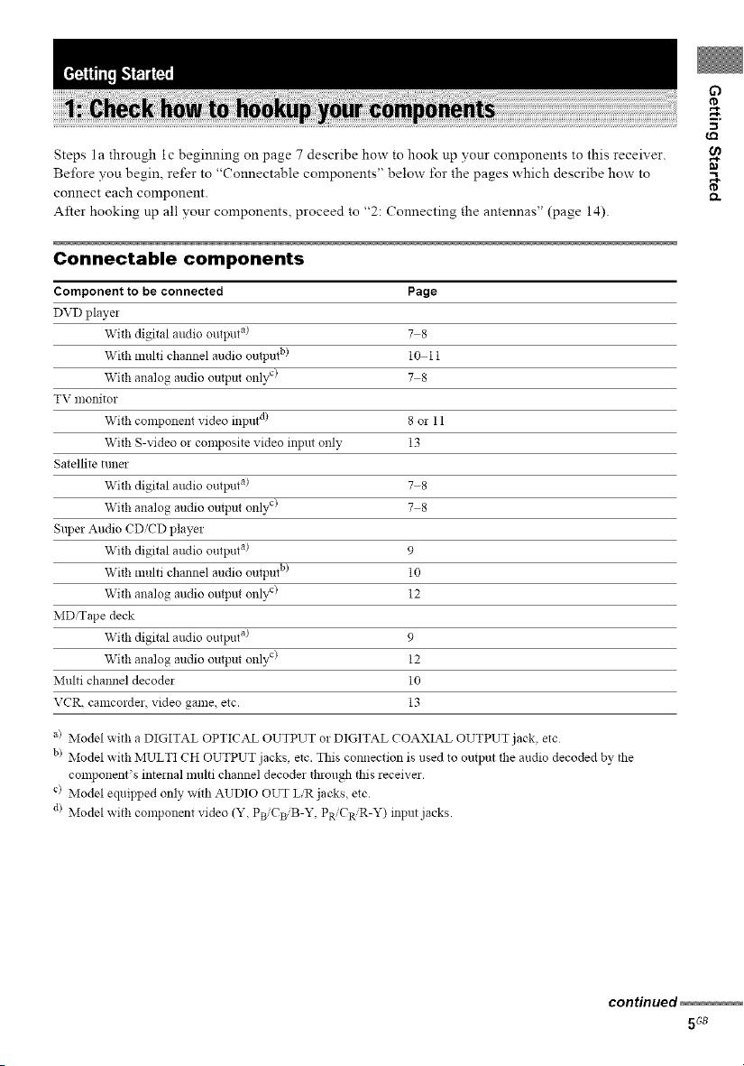
Steps la through ic beginning on page 7 describe how to hook up your components to this receiver.
Be/bre you begin, refer to "Connectable components" below/'or the pages which describe how to
connect each component.
After hooking up all your components, proceed to "2: Connecting the antennas" (page 14).
Connectable components
Component to be connected Page
DVD player
With digital audio output a) 7 8
With multi channel audio output b) 10 11
With analog audio output onlv c) 7 8
TV monitor
With component video input d) 8 or 11
With S-video or composite video input only 13
Satellite tuna
With digital audio output a) 7 8
With analog audio output only c) 7 8
Super Audio CD/CD player
With digital audio output a) 9
With multi channel audio output b) 10
With analog audio output onl} x) 12
MD'Tape deck
With digital audio output a) 9
With analog audio output only c) 12
Multi channel decoder 10
VCR, camcordez, video game, etc. 13
_a
e,
a) Model with a DIGITAL OPTICAL OUTPUT or DIGITAL COAXIAL OUTPUT jack, etc
b) Model with MULTI CH OUTPUT jacks, etc. This connection is used to output the audio decoded by the
component's internal multi channel decodes through this receiver.
c) Model equipped only with AUDIO OUT LiR jacks, etc.
d> Model with component video (Y, PBiCBiB-Y, PR/CR'R-Y) input jacks.
continued
5Gs
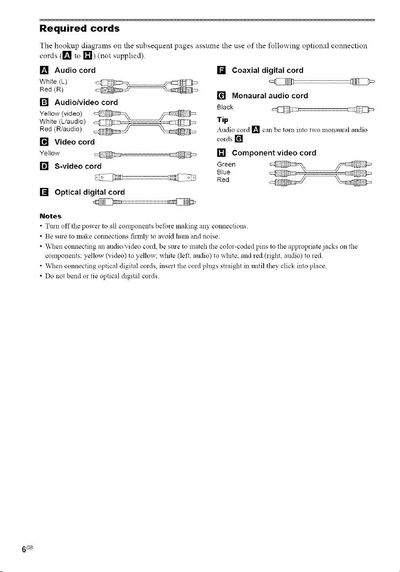
Required cords
The hookup diagrams on the subsequent pages assume the use of the following optiona! connection
cords ([] to _111) (not supplied).
[] Audio cord
White (L)
Red (R)
[] Audio/video cord
White (L/audio)
Yellow (video)
Red (R/audio)
[] Video cord
Ye;Iow @ @
[] S-video cord
[] Optical digital cord
Notes
• Tmn off the power to all components be%_e making any connections.
• Be sure to make connections firmly to avoid hum and noise.
• When connecting an audio/video cord, be sine to match the color-coded pins to the appropriate jacks on the
components: yellow (video) to yellow; white (left, audio) to white and red (right, audio) to red.
• When connecting optical digital cords, inse_t the cord plugs straight in lmtil they click into place.
• Do not bend or tie optical digital cords
[] Coaxial digital cord
[] Monaural audio cord
Black @
Tip
Audio cold [] can be tom into two monaural andio
cords []
[] Component video cord
Green
Blue
Red
6 GB
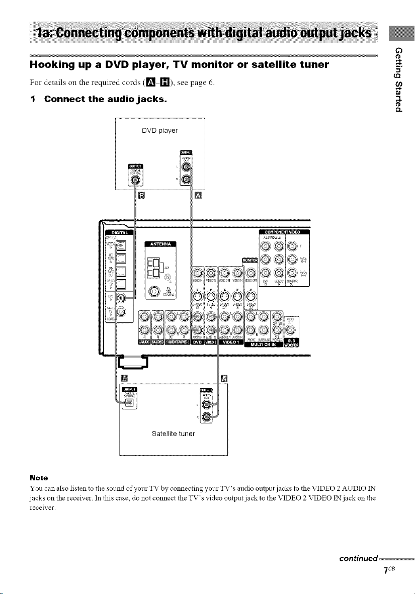
Hooking up a DVD player, TV monitor or satellite tuner w,
For details o,1the required cords ([] _!), see page 6.
1 Connect the audio jacks.
DVD player
[] []
3
3
_!i,
[]
Q
_Q
[] N
Satellite tuner }
Note
You can also listen _o the solmd of yore TV by connecting your TV's andio output jacks to the VIDEO 2 AUDIO IN
jacks on the receh'er In this case, do not connect the TV's video output jack to the VIDEO 2 VIDEO IN jack on file
receiver•
continued
7Gs
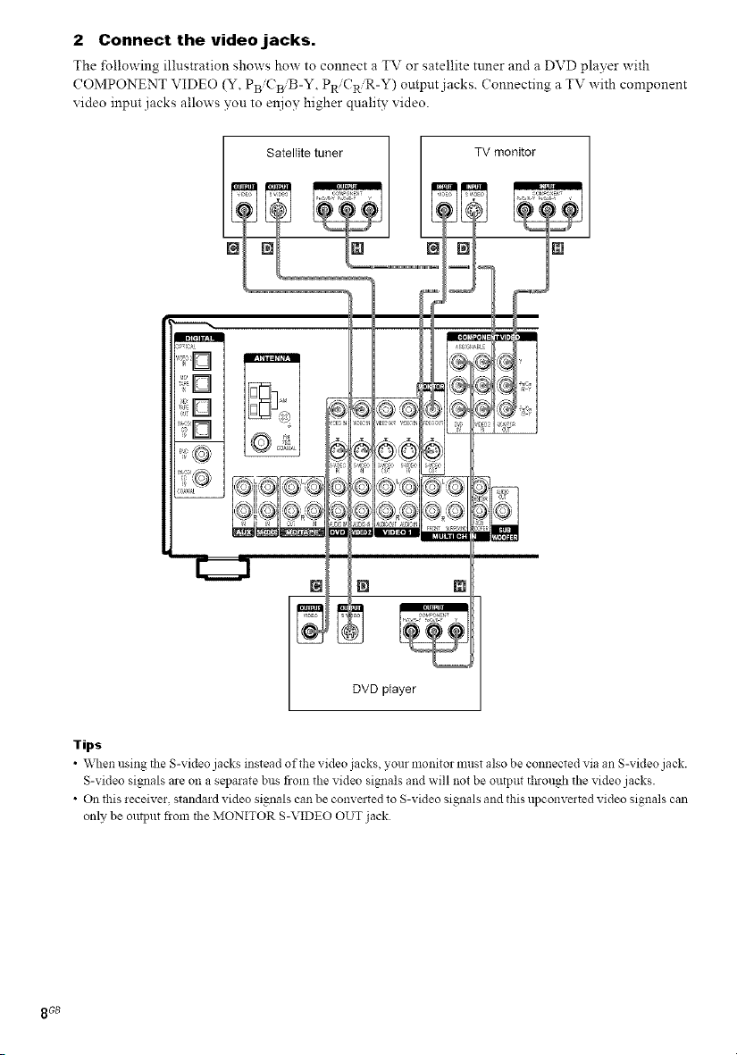
2 Connect the video jacks.
The following illustration shows how to connect a TV or satellite tuner and a DVD player with
COMPONENT VIDEO (Y, PBiCBiB-Y, PR CR'R-Y) output jacks. Connecting a TV with component
video input jacks allows you to e:_ioy higher quality video.
Satellite tuner TV monitor
DVD player
Tips
• When using the S-video jacks instead of the video jacks, your n:onitor nmst also be connected via an S-video jack.
S-video signals are on a separate bus from the video signals and will not be output through the video jacks.
• On this receiver, standard video signals ca:: be conve:ted to S-video signals and this upconve:ted video signals can
only be output fiom the MONITOR S-VIDEO OUT jack
8GB
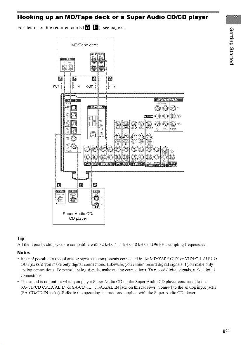
Hooking up an MD/Tape deck or a Super Audio CD/CD player
For details on the required cords ([] _1), see page 6.
MD/Tape deck
@ N N
OUT _ IN OUT
IN
x-'x 4 × _-,
O)I[ G (©
G)
.g
Super Audio CD/
CD player
Tip
All the digital andio jacks ae compatible with 32 kHz, 44 1 kHz, 48 kHz and 96 kHz sampling fiequencies
Notes
• It is not possible to zecord analog signals to components connected to the MDiTAPE OUT or VIDEO 1 AUDIO
OUT jacks if you make only digital connections. Likewise, you cannot record digital signals if you make only
analog connections To record analog signals, make analog connections. To record digital signals, make digital
co!lnections.
• The soaed is not output when you play a Super Audio CD on the Super Audio CD player connected to the
SA-CDiCD OPTICAL IN or SA-CDiCD COAXIAL IN jack on this receiver. Connect to the analog input jacks
(SA-CD'CD IN jacks). Refer to the operating instructions supplied with the Super Audio CD player.
9 GB
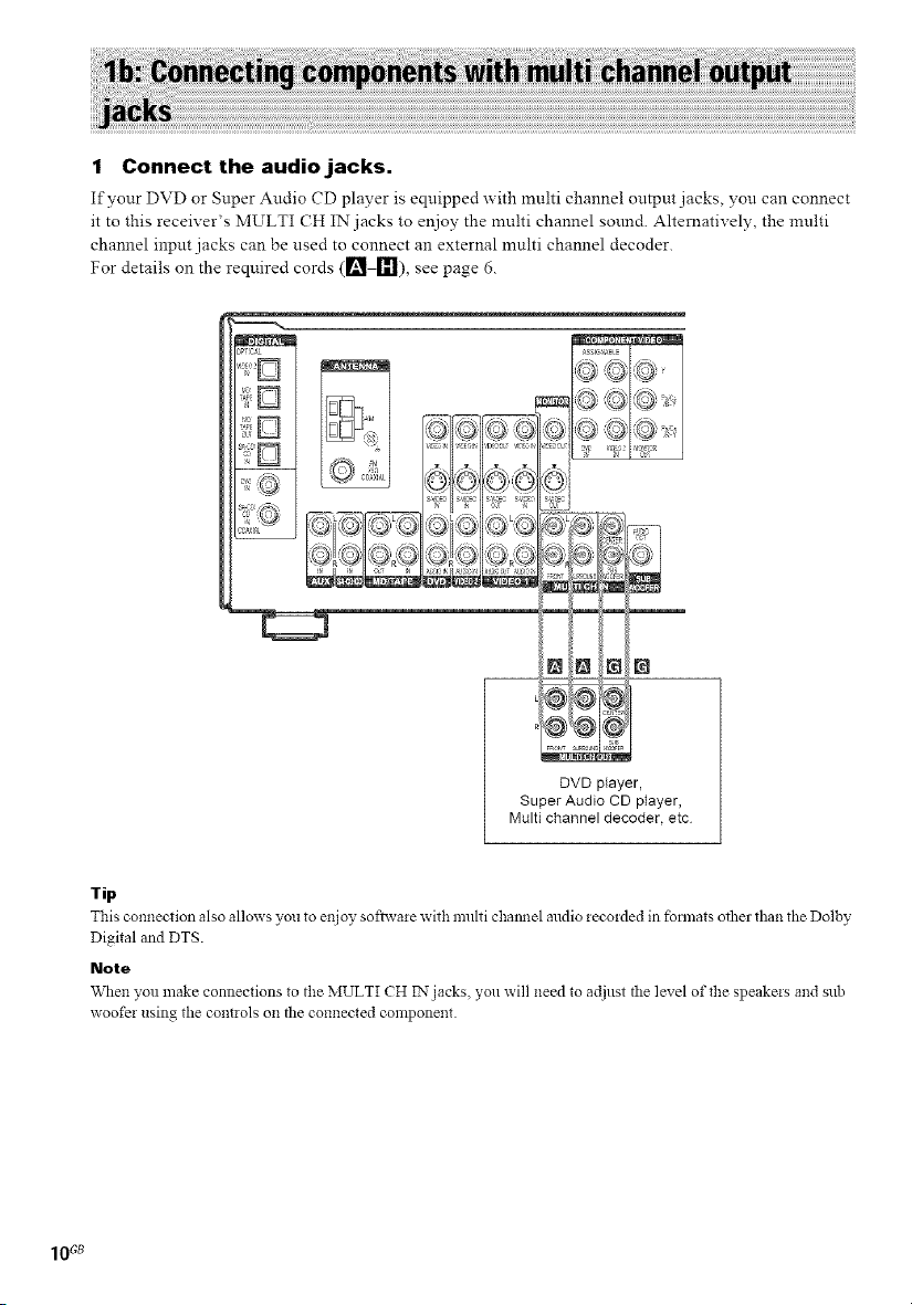
1 Connect the audio jacks.
If your DVD or Super Audio CD player is equipped with multi channel output jacks, yon can connect
it to this receiver's MULTI CH IN jacks to enjoy the multi channel smmd. Alternatively, the multi
channel input jacks can be used to connect an external multi channel decoder.
For details on the required cords (ri_ [1_1),see page 6.
,_TtC_Z
_SSl6_S{E
@ @ ,Q
[]
_C4 ×,
_s s E
, x- "x z. z
N N ra IN
@Y@'/N
DVD player,
Super Audio CD player,
Multi channel decoder, etc
Tip
This connection also allows you _oenjoy sofiwaze with multi cha_mel audio zeco_ded in fbm_ats other than the Dolby
Digital and DTS.
Note
When you make connections to the MULTI CH IN jacks you will need to adjust the level of the speakezs and sub
woofer using the controls on the connected component.
10_
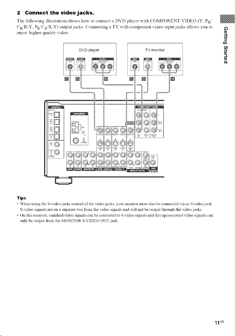
2 Connect the video jacks.
The following illustration shows how to connect a DVD player with (OMPONENT VIDEO (Y, PB/
CBiB-Y , PR CR R-Y) output jacks. (onnecting a TV with component video input jacks allows you to
enjoy higher quality video.
TV monitor
N
63
w,
lips
• When using the S-video jacks instead of the video jacks, your monitor must also be connected via an S-video jack
S-video signals are on a separate bus flom lhe video signals and will not be output through the video jacks
• On this receiver, standard video signals can be converted to S-video signals and this upconvated video signals can
only be output flora the MONITOR S-VIDEO OUT jack.
11Gs
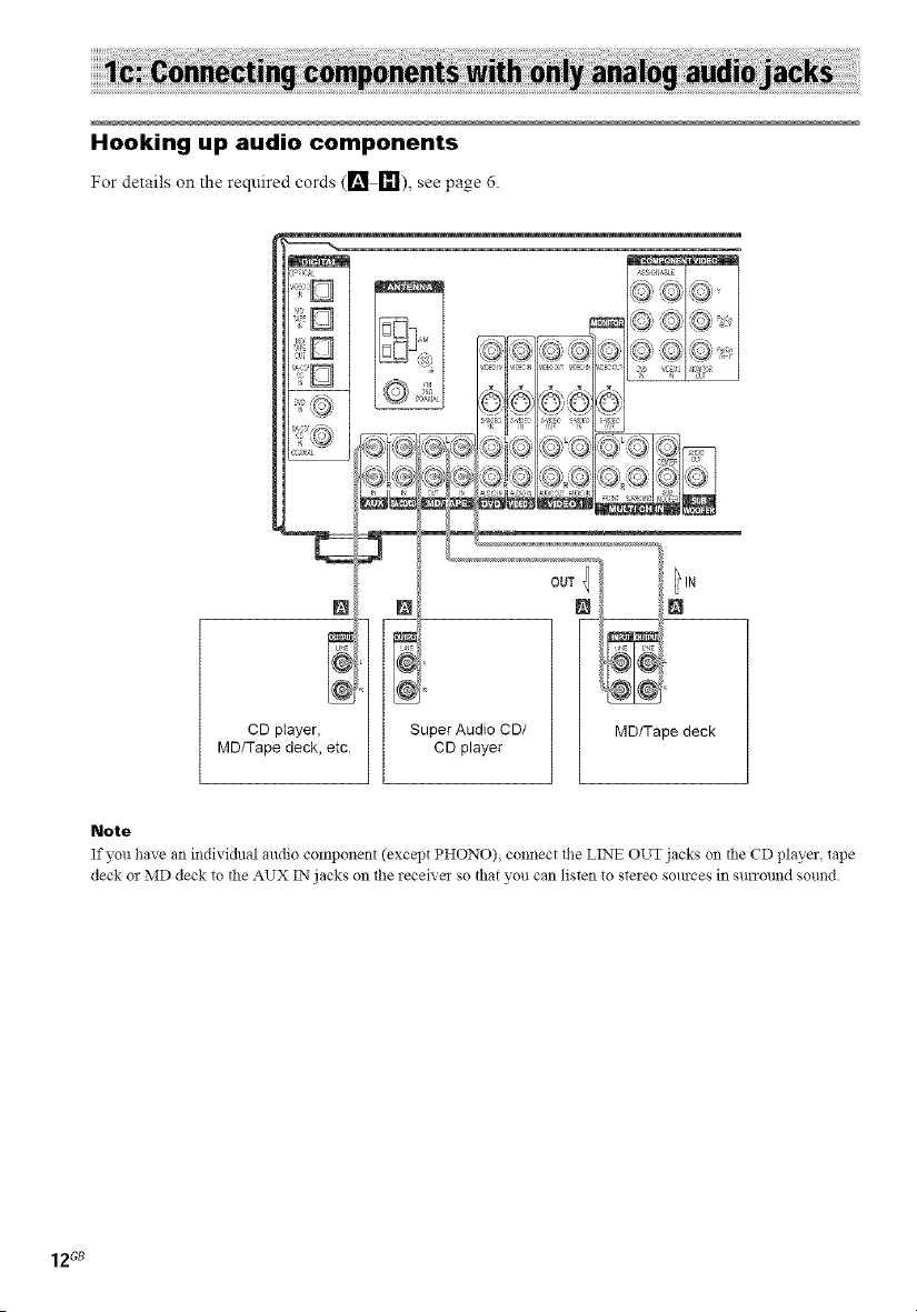
Hooking up audio components
For details on the required cords (ri_ _!), see page 6.
_SS_Sr_,SLE
• , z ,\ / \
=<le s:l_@I
(z h
d
L__:"_1"__ I
i- _r .q
..... @A
©;;It=D;_ y,",_
S_'ECI,,SE: S:-, S:EC
N
CD player, Super Audio CD/
MD/Tape deck, etc. CD player
Note
If you have an individual audio component (except PHONO) connect the LINE OUT jacks on the CD player tape
deck or MD deck to the AUX IN jacks on the receiver so that you can listen to steieo sources in surround sound.
MD/Tape deck
12G8
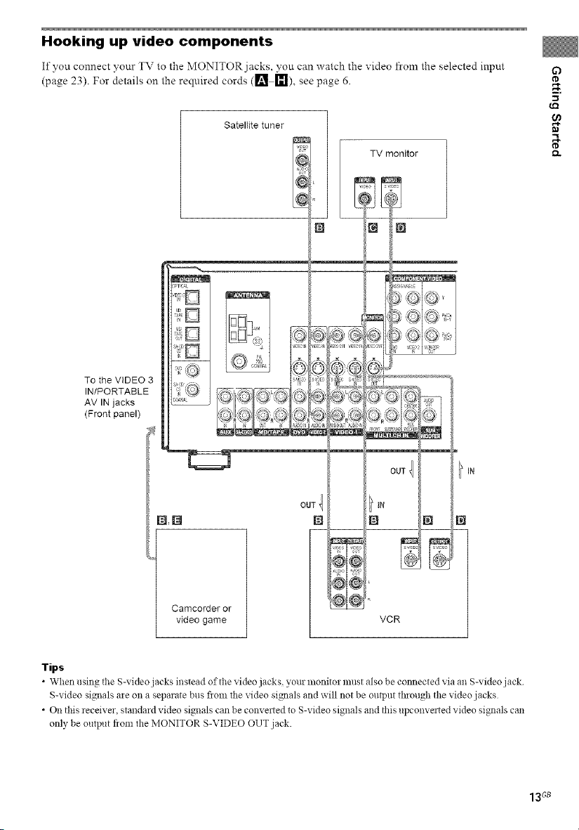
Hooking up video components
If you connect your TV to the MONITOR jacks, you can watch the video from the selected input
(page 23). For details on the required cords ([] [_1), see page 6.
SatelIite tuner
if)
w,
To the VIDEO 3
IN/PORTABLE
AV IN jacks
(Front panel)
TV monitor
€-,
Camcorderor
video game VCR
Tips
• When using the S-video jacks instead of the video jacks, your monitor must also be connected via an S-video jack
S-video signals are on a separate bus flora lhe video signals and will not be output thlough the video jacks
• On this receiver, standard video signals can be converted to S-video signals and this upconvated video signals can
only be output flora the MONITOR S-VIDEO OUT jack.
13Gs
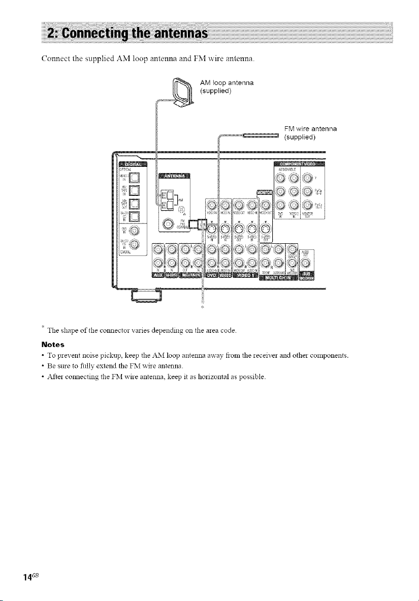
Connect the supplied AM loop antenna and FM wire antenna.
AM loop antenna
(supplied)
FM wire antenna
(supplied)
* The shape of the connecto! varies depending on the area code
Notes
• To prevent noise pickup keep the AM loop antenna away from tile leceive_ and otbe_ components.
• Be sure to fiflly extend tile FM wire antenna.
• After cmmecting the FM wire antenna, keep it as horizontal as possible.
14Gs
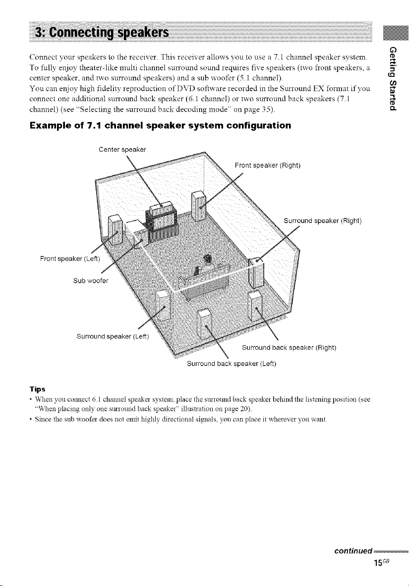
Connect your speakers to the receiver. This receiver allows you to use a 7.1 channel speaker system.
To flflly enjoy theater-like multi channel surround sound requires five speakers (two front speakers, a .,_
center speaker, and two surround speakers) and a sub woofer (5.1 channel).
You can enjoy high fidelity reproduction of DVD software recorded in the Surround EX format if vou "_
connect one additional surround back speaker (6.1 channe!) or two surround back speakers (7.1
channel) (see "Selecting the surromld back decoding mode" on page 35). _-
Example of 7.1 channel speaker system configuration
Center speaker
Front speaker (Right)
Surround speaker (Right)
Front speaker (Left)
Sub woofer
Surround speaker(Left)
Surround back speaker (Right)
Surround back speaker (Left)
63
w.
t_
Tips
• When you connect 6 1 channel speaker system, place the SmTound back speaker behind the listening position (see
"When placing only one SmTound back speaker" illustration on page 20).
• Since the sub woofe_ does not emit highly directional signals, you can place it wherever you want
continued
15Gs
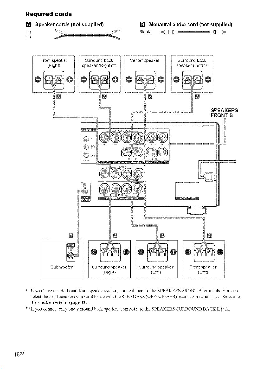
Required cords
[] Speaker cords (not supplied)
(-)
[] Monaural audio cord (not supplied)
Black @
N
Sub wooer
* If you have an additional front speaker system, connect them to the SPEAKERS FRONT B temfinals You can
select the front speakers you want to use with the SPEAKERS (OFF'A/BiA+B) button. Fm details, see "Selecting
the speaker system" (page 43)
** If you connect only one sunound back speaker, connect it to the SPEAKERS SURROL2qD BACK L jack.
16c8
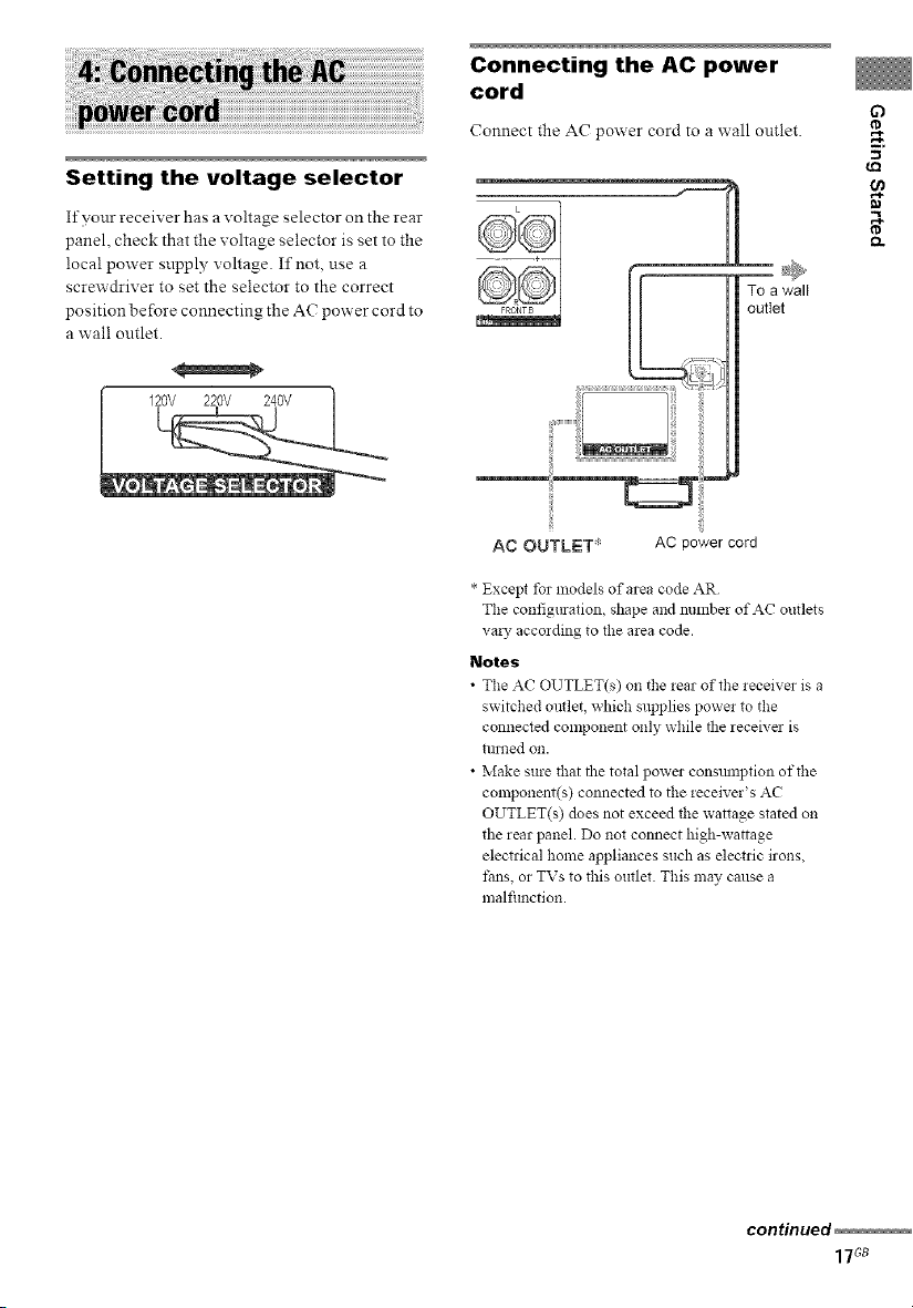
Setting the voltage selector
If yonr receiver has a voltage selector on the rear
panel, check that the voltage selector is set to the
local power snpply voltage. If not, use a
screwdriver to set the selector to the correct
position before connecting the AC power cord to
a wall outlet.
120V 220V 240V
Connecting the AC power
cord
Connect the AC power cord to a wall outlet.
AC OUTLET* AC power cord
* Except tbr models of area code AR
The configmation, shape and number of AC outlets
va!), according to the area code.
Notes
• The AC OUTLET(s) on the lear of the leceiver is a
switched outlet, which supplies power to the
connected component only while the receive; is
till!led OI1.
• Make sure that the total power consmnption of the
component(s) connected to the receiver's AC
OUTLET(s) does not exceed the wattage slated on
the rear panel. Do not connect high-wattage
electrical home appliances such as electric irons,
fans, or TVs to this outlet. This may cause a
malfimction.
Q
.g
w_
gl
continued
17Gs
Performing initial setup
operations
Be_re using the receiver _r the first time,
initialize the receiver by pertSnning the
following procedure.
This procedure can also be used to return
settings you have made to their factory defaults.
Use the buttons oll the receiver for the operation.
1 Press I/(_) to turn off the receiver.
2 Hold down I/(_ for 5 seconds.
"PUSH" and "ENTER" appears in the
display alternatingly.
3 Press ENTER.
"CLEARING" appears in the display _r a
while, then "CLEARED" appears.
The IBllowing are reset to their factory
settings.
• All settings in the SET UP, LEVEL, EQ
and CUSTOMIZE menus.
• The sound field memorized for each
input and preset station.
• All sound field parameters.
• Allpreset stations.
• All index names for inputs and preset
stations.
• MASTER VOLUME + is set to"VOL
MIN".
• Input is set to DVD.
You can use the SET UP menu to set the size.
distance and location of the speakers connected
to this receiver.
1 Press I/@ to turn on the receiver.
Press MAIN MENU repeatedly to select
",<SET UP>".
3 Press < or > repeatedly to select the
parameter you want to adjust,
For details, see "Speaker setup parameters"
below.
Note
Some speaker setup items may a_ear dimmed in
the display This means thai the?, have been
adjusted mltomatically due to other speaker
settings or may not be adjustable.
4 Turn the -1+ jog dial to select the
setting you want,
The setting is entered automatically.
Note
Pless ENTER on the leceiver if you select the
setting tbr "SP PAT X X".
5 Repeat steps 3 and 4 until you have set
all of the items that follow.
Speaker setup parameters
The initial settings are underlined.
• XXXX SET (Speaker easy setup)
• EASY
If you want to set up your speakers
automatica!ly, select "EASY SET". You can
select a pre-defined speaker pattern (see the
supplied "Easy Setup Guide").
• NORM
If you want to adjust the settings of each
speaker manually, select "NORM SET".
18G8
• SP, PAT. X -X (Speaker setup pattern)
When you select "EASY SET", select the
speaker setup pattern. Turn the _+ jog dial to
select the speaker setup pattern and press
ENTER to enter the selection. Check yonr
speaker pattern using the snpplied "Easy Setup
Guide".
• _ S.W. XXX (Sub woofer selection)
• YES
If you connect a sub woofer, select "YES".
• NO
If you did not connect a sub woofer, select
"NO". The front speakers are automatically
set to "LARGE" and you cannot change this
setting. This activates the bass redirection
circuitry and outputs the LFE signals from
other speakers.
• In order to take full advantage of the Dolby
Digital bass redirection circuitry, we
recommend that you set the cut off frequency
on the sub woofer as high as possible.
• :!it_ !_i XXXXX (Front speakers size)
• LARGE
If you connect large speakers that will
effectively reprodnce bass frequencies, select
"LARGE". Nornrally, select "LARGE".
• SMALL
If the sound is distorted, or you feel a lack of
surround effects when using multi channel
surround sormd, select "SMALL" to activate
the bass redirection circuitry and output the
front channel bass freqnencies from the sub
woofer. When the front speakers are set to
"SMALL", the center, snrround and surround
back speakers are also automatically set to
"SMALL" (unless previously set to "NO").
• iu; XXXXX (Center speaker size)
• LARGE
If you connect a large speaker that will
effectively reproduce bass frequencies, select
"LARGE". Normally, select "LARGE".
However, if the front speakers are set to
"SMALL", you cannot set the center speaker
to "LARGE".
• SMALL
If the sound is distorted, or you feel a lack of
surround effects when using multi channel
surround sound, select "SMALL" to activate
the bass redirection circuitry and output the
center channel bass frequencies from the front
speakers (if set to "LARGE") or snb woofer, a)
• NO
If you did not connect a center speaker, select
"NO". The sonnd of the center channel will be
output from the front speakers, b)
• @ in XXXXX (Surround speakers size)
• LARGE
If you connect large speakers that will
effectively reproduce bass frequencies, select
"LARGE". Normally, select "LARGE".
However, if the front speakers are set to
"SMALL", you cannot set the surround
speakers to "LARGE".
• SMALL
If the sound is distorted, or you feel a lack of
surround effects when using nmlti channel
surround sound, select "SMALL" to activate
the bass redirection circuitry and output the
surround channel bass frequencies from the
sub woofer or other "LARGE" speakers.
• NO
If you did not connect snrround speakers,
select "NO". c)
C)
.g
tt_
t_
continued
19G8
• :_:!_v_ xxxxxx
(Surround back speaker selection)
• DUAL
If you connect two surround back speakers,
select "DUAL". The sound will be output to a
maximum of 7.1 channels.
• SINGLE
If you comlect only one surround back
speaker, select "SINGLE". The sound will be
output to a maximum of 6.1 channels.
• NO
If you did not connect surround back speaker,
select "NO".
Tips
• a)-c) conespond to tile following Dolby Pro Logic
lllodes
a) NO PcMAL
b) PHANTOM
c) 3 STEREO
• The "LARGE" and "SMALL" settings tbr each
speaker deternfine whether the internal sound
processor will cut the bass signal from that channel.
When the bass is cut flora a channel, the bass
redirection circuitry sends the corresponding bass
frequencies to tlle sub woofer or other "LARGE"
speakers
However, since bass solmds have a certain amolmt of
directionality, it is best not to cut them, if possible.
Therefore, even when using small speakers, you can
set them to "LARGE" if you want to output tile bass
fiequencies from that speaker On the other hand, if
you are using a large speaker, but prefer not to have
bass frequencies olltpllt from that speaker, set it to
"SMALL".
If the ovelall sound level is lower than you prefer, set
all speakers to "LARGE". If there is not enough bass,
you can use tile BASS parameter in tlle EQ menu to
boost the bass levels. To adjust the bass, see page 39
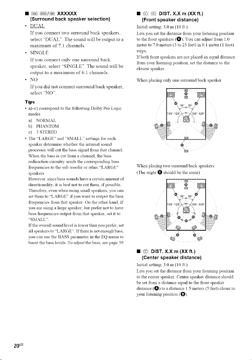
• :_: _ DIST. X.X rn (XX ft.)
(Front speaker distance)
Initial setting: 3.0 m (10 fl)
Lets you set tile distance flora yore listening position
to the fiont speakers (_). You can adjust flora 10
mete_ to 70 meters (3 to 23 feet) in 0 1 meter (1 toot)
steps.
If both front speakers are not placed an eqlml distance
from your listening position, set the distance to the
closest speaker
When placing only one sunound back speaker
When placing two sunotmd back speakers
(Tile angle _ should be the same)
• (_ DIST. X.X m (XX ft.)
(Center speaker distance)
Initial setting: 30 m (10 ft.)
Lets 5vu set the distance from yore listening position
to tile center speaker. Center speaker distance should
be set fioln a distance equal to the front speaker
distance (_) to a distance 1.5 meters (5 feet) closer to
your listening position (_)
20 Gs
 Loading...