

Sony STR-DE245/DE345, STR-DE245, STR-DE345 Service Manual
STR-DE245/DE345
AEP Model
UK Model
E Model
Australian Model
STR-DE245/DE345
US Model
Canadian Model
Chinese Model
PX Model
STR-DE345
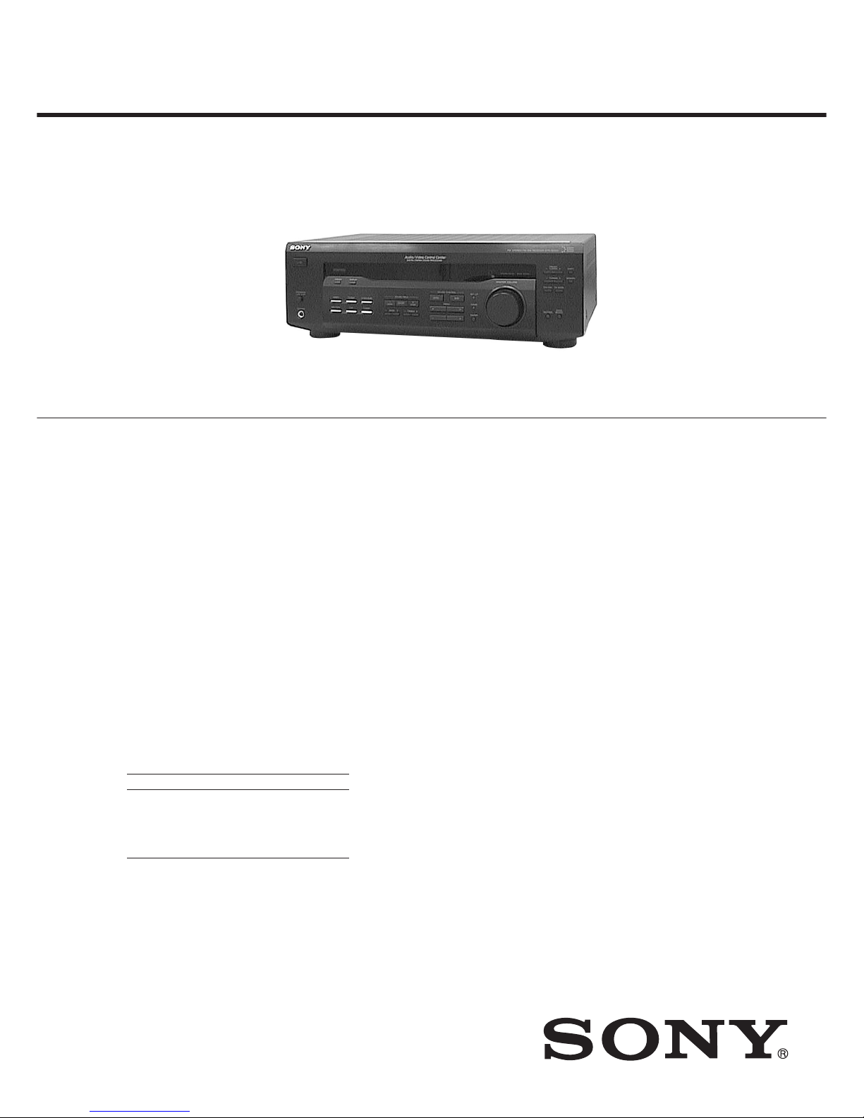
SERVICE MANUAL
FM STEREO FM-AM RECEIVER
SPECIFICATIONS
Manufactured under license from Dolby Laboratories Licensing
Corporation.
“DOLBY” the double-D symbol ; “AC-3” and “Pro Logic” are
trademarks of Dolby Laboratories Licensing Corporation.
Photo: STR-DE345
— Continued on next page —
POWER OUTPUT AND TOTAL HARMONIC
DISTORTION
With 8-ohm load, both channels driven, from 20 –
20,000 Hz rated 100 watts per channel minimum
RMS power, with no more than 0.09% total
harmonic distortion from 250 milliwatts to rated
output.
Amplifier section
Rated Power Output at (8 Ω at 20 Hz – 20 kHz,
Stereo Mode THD 0.09 %)
100W + 100W
Reference Power Output (8Ω at 1 kHz, THD 0.7%)
Front: 100 W + 100 W
Center: 100 W
Rear: 100 W + 100 W
Frequency response TV/SAT, CD, MD/TAPE,
VIDEO, 5.1CH/DVD
10 – 50 kHz dB
Inputs
Sensitivity Impedance S/N
CD,
5.1CH/
DVD,
MD/TAPE, 150 mV
50
85 dB
TV/SAT,
kilohms
VIDEO
Outputs MD/TAPE REC OUT:
Voltage: 150 mV,
Impedance: 10 kilohms
VIDEO AUDIO OUT:
Voltage: 150 mV,
Impedance: 10 kilohms
SUB WOOFER:
Voltage: 2 V
Impedance: 1 kilohms
PHONES: Accepts low
and high impedance
headphones
Muting Full mute
BASS BOOST +6 dB at 70 Hz
TONE ±6 dB at 100 Hz and
10 kHz
Tuner section
FM Stereo, FM/AM superheterodyne tuner
FM tuner section
Tuning range 87.5 – 108.0 MHz
Antenna terminals 75 Ω, unbalanced
Intermediate frequency 10.7 MHz
Sensitivity Mono: 18.3 dBf, 4.5 µV
Stereo: 38.3 dBf, 45 µV
Usable sensitivity 11.2 dBf, 2 µV (IHF)
S/N Mono: 76 dB
Stereo: 70 dB
Harmonic Mono: 0.3 %
distortion at 1 kHz Stereo: 0.5 %
Separation 45 dB at 1 kHz
Frequency response 30 Hz –15 kHz dB
Selectivity 60 dB at 400 kHz
+0.5
–2.0
+0.5
–2.0
AM tuner section
Tuning range 10 kHz interval*
530 – 1,710 kHz
9 kHz interval
531 – 1,710 kHz
Antenna Loop antenna
Intermediate frequency 450 kHz
Usable sensitivity 50 dB/m (at 1,000 kHz
or 999 kHz)
S/N 54 dB (at 50 mV/m)
Harmonic distortion 0.5 % (50 mV/m, 400
Hz)
Selectivity At 10 kHz: 40 dB
At 9 kHz: 35 dB
* You can change the AM tuning interval between 9
kHz and 10 kHz. Turn off the receiver and press
the ?/1 (power) for more than 4 seconds until
“INITIAL” appears.
1) After turning in any AM station, turn off the
receiver.
2) Hold down PRESET TUNING + button and
press the ?/1 (power) button .
“9 k STEP” appears.
To change to 10 k Step, repeat step 1 and 2
until “10 k STEP” appears. Note that all preset
stations, index names and sound field are
cleared after you make the procedure above.
Ver 1.0 2000. 02
2
VIDEO section
Inputs VIDEO, TV/SAT, 5.1CH/DVD:
1 Vp-p 75 Ω
Outputs VIDEO, MONITOR:
1 Vp-p 75 Ω
General
System Tuner section: PLL
quartz-locked digital
synthesizer system
Preamplifier section:
Low-noise NF type
equalizer
Power amplifier section:
Pure-complementary
SEPP
Power requirements 120 V AC, 60 Hz
Power consumption 235 W
Dimensions 17 × 56/8 × 12 inches)
(430 × 145 × 304 mm)
Mass (Aporox.) 7.3 kg (16 lb 2 oz)
Supplid accessories FM wire antenna (1)
AM loop antenna (1)
Remote commander (remote) (1)
Size AA (R6) batteries (2)
Operating Instructions of the remote RM-PP404
Design and specifications are subject to change without notice.
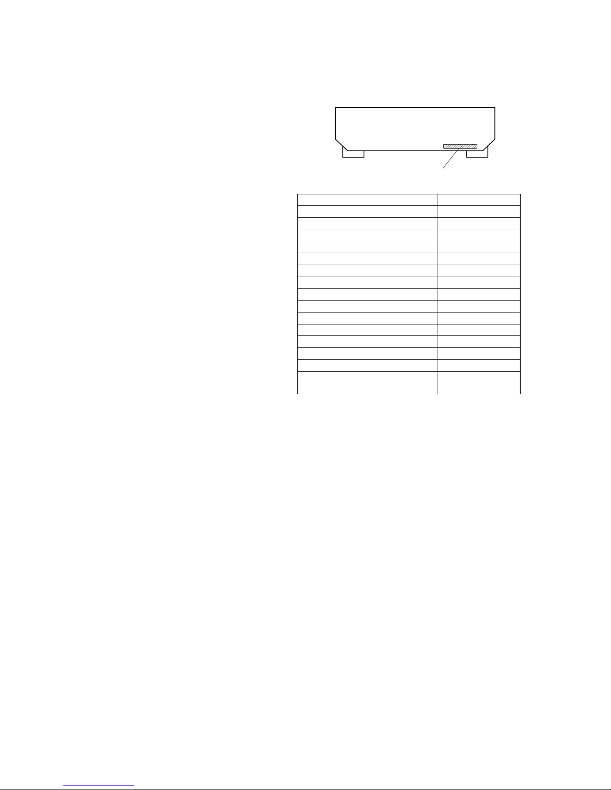
MODEL IDENTIFICATION
— BACK PANEL —
Parts No.
MODEL PARTS No.
DE345: US model 4-226-462-0s
DE345: Canadian model 4-226-462-1s
DE345: Australian model 4-226-462-2s
DE345: Singapore, Malaysia model 4-226-462-3s
DE345: Chinese model 4-226-462-4s
DE345: E, Saudi Arabia, PX model 4-226-462-5s
DE345: AEP model 4-226-462-6s
DE345: Russian, East European model 4-226-462-7s
DE345: Mexican model 4-226-462-8s
DE345: Argentine model 4-226-462-9s
DE245: Australian model 4-226-468-2s
DE245: Singapore, Malaysia model 4-226-468-3s
DE245: E, Saudi Arabia model 4-226-468-4s
DE245: AEP, UK model 4-226-468-5s
DE245: Mexican, Russian,
East European model
4-226-468-6s
3
SAFETY-RELATED COMPONENT WARNING!!
COMPONENTS IDENTIFIED BY MARK 0 OR DOTTED LINE WITH
MARK 0 ON THE SCHEMATIC DIAGRAMS AND IN THE PARTS
LIST ARE CRITICAL TO SAFE OPERATION. REPLACE THESE
COMPONENTS WITH SONY PARTS WHOSE PART NUMBERS
APPEAR AS SHOWN IN THIS MANUAL OR IN SUPPLEMENTS
PUBLISHED BY SONY .
After correcting the original service problem, perform the
following safety checks before releasing the set to the customer:
Check the antenna terminals, metal trim, “metallized” knobs, screws,
and all other exposed metal parts for A C leakage. Check leakage as
described below.
LEAKAGE
The A C leakage from any e xposed metal part to earth ground and
from all exposed metal parts to any exposed metal part having a
return to chassis, must not exceed 0.5 mA (500 microamperes).
Leakage current can be measured by any one of three methods.
1. A commercial leakage tester, such as the Simpson 229 or RCA
WT -540A. Follo w the manufacturers’ instructions to use these
instruments.
2. A battery-operated AC milliammeter. The Data Precision 245
digital multimeter is suitable for this job.
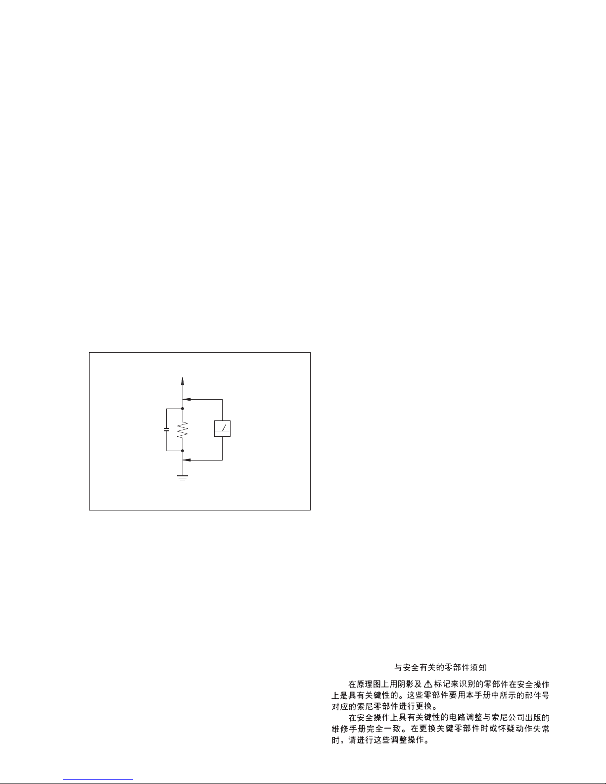
3. Measuring the voltage drop across a resistor by means of a
VOM or battery-operated AC v oltmeter. The “limit” indication
is 0.75 V, so analog meters must ha v e an accurate lo w-voltage
scale. The Simpson 250 and Sanwa SH-63Trd are examples of
a passive VOM that is suitable. Nearly all battery operated
digital multimeters that have a 2V AC range are suitable. (See
Fig. A)
SAFETY CHECK-OUT
T o Exposed Metal
Parts on Set
0.15
µ
F
1.5 k
Ω
AC
Voltmeter
(0.75 V)
Earth Ground
Fig. A. Using an A C v oltmeter to check A C leakage.
ATTENTION AU COMPOSANT AYANT RAPPORT
À LA SÉCURITÉ!
LES COMPOSANTS IDENTIFÉS P AR UNE MARQUE 0 SUR LES
DIAGRAMMES SCHÉMA TIQUES ET LA LISTE DES PIÈCES SONT
CRITIQUES POUR LA SÉCURITÉ DE FONCTIONNEMENT. NE
REMPLACER CES COMPOSANTS QUE PAR DES PIÈSES SONY
DONT LES NUMÉROS SONT DONNÉS DANS CE MANUEL OU
DANS LES SUPPÉMENTS PUBLIÉS PAR SONY.
TABLE OF CONTENTS
1. GENERAL ·········································································· 4
2. TEST MODE······································································ 6
3. DIAGRAMS
3-1. Block Diagram ······························································ 7
3-2. IC Block Diagrams ························································ 8
3-3. IC Pin Function Description ·········································· 8
3-4. Circuit Boards Location ················································ 9
3-5. Printed Wiring Board Main Section ·························· 10
3-6. Schematic Diagram Main Section (1/3) ···················· 11
3-7. Schematic Diagram Main Section (2/3) ···················· 12
3-8. Schematic Diagram Main Section (3/3) ···················· 13
3-9. Printed Wiring Board Panel Section·························· 14
3-10.Schematic Diagram Panel Section ··························· 15
3-11.Printed Wiring Board Power Section ························ 16
3-12.Schematic Diagram Power Section ·························· 17
3-13.Printed Wiring Board Video Section ························· 18
3-14.Schematic Diagram Video Section ··························· 18
4. EXPLODED VIEWS
4-1. Front Panel Section ····················································· 19
4-2. Chassis Section ···························································· 20
5. ELECTRICAL PARTS LIST······································· 21
4
SECTION 1
GENERAL
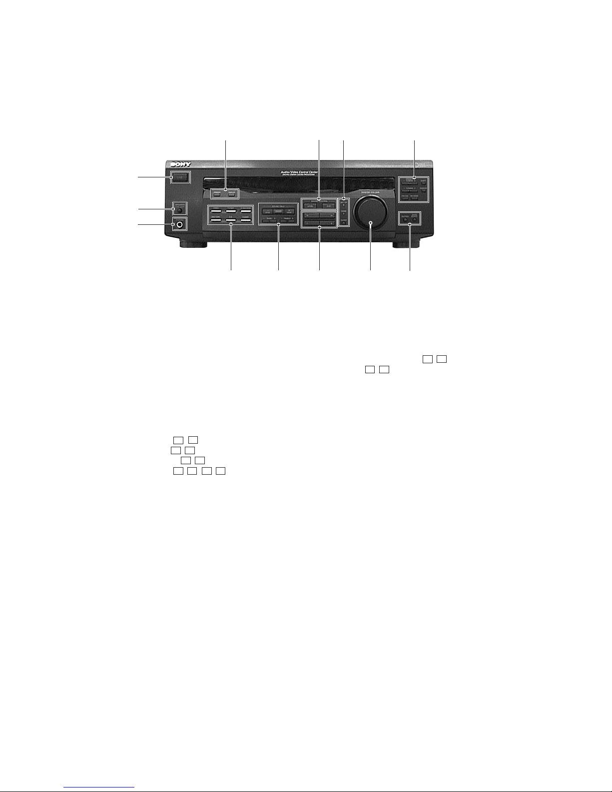
Front Panel
1
qs
4
5
6
7
8
9
qa
2
3
0
1 I/1 (POWER) button
2 SPEAKERS ON/OFF SWITCH button
3 PHONE jack
4 VIDEO button
TV/SAT button
5.1CH/DVD button
MD/TAPE button
CD button
TUNER button
5 SOUND FIELD ON/OFF,
MODE + , – buttons
BASS + , – buttons
TREBLE + , – buttons
6 MENU < , > , + , – buttons
7 MASTER VOLUME control
8 MUTING button
BASS BOOST botton
9 PRESET/PTY SELECT + , – buttons
TUNING + , – buttons
FM/AM button
FM MODE button
SHIFT button
MEMORY button
0 SET UP button
NAME button
ENTER button
qa SOUND CONTROL LEVEL,SUR buttons
qs DIMMER button
DISPLAY button

5
Rear Panel
This section is extracted
from instruction manual.
6
SECTION 2
TEST MODE
SOFTWARE VERSION DISPLAY MODE
* The software version is displayed.
* Procedure:
While depressing the TUNER and the VIDEO buttons
simultaneously, press the po wer [?/1] button to turn on the main
power . The model name, destination and the software version are
displayed.
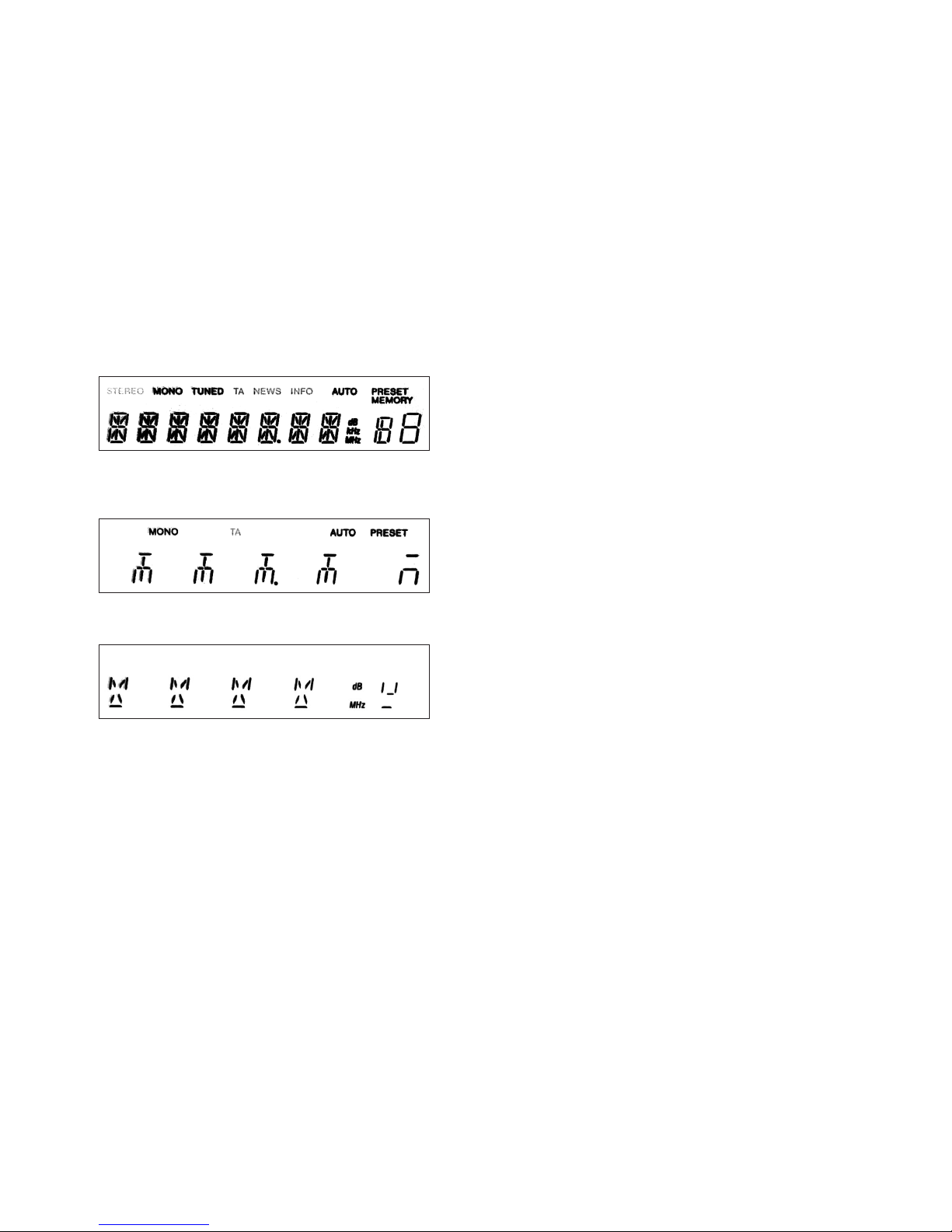
FLUORESCENT INDICATOR TUBE TEST MODE
* All fluorescent segments are tested. When this test is activated,
all segments turn on at the same time, then each segment turns on
one after another.
* Procedure:
While depressing the TV/SA T and the CD buttons simultaneously ,
press the power [?/1] button to turn on the main power.
1. All segments turn on.
SET UP, SOUND FIELD, BASS BOOST and MUTING LED
turn on.
2. Press the VIDEO button, confirm display
BASS BOOST, MUTING, SET UP and NAME LED turn on.
3. Press the VIDEO button, confirm display
SOUND CONTROL LEVEL, SOUND CONTROL SUR and
SOUND FIELD LED turn on.
4. Press the VIDEO button, All segments turn off.
5. Every pressing of the VIDEO b utton turns on each segment one
after another in the following order.
(Not only the VIDEO button, b ut also the other b uttons such as
TV/SAT, MD/TAPE, CD, TUNER can be used.)
FACTORY SET MODE
* All preset contents are reset to the default setting.
* Procedure:
While depressing the VIDEO and the CD buttons simultaneously ,
press the power [?/1] button to turn on the main power. The
message FACTOR Y appears and the present contents are reset to
the default values.
ALL CLEAR MODE
* All preset contents are cleared when this mode is activated. Use
this mode before returning the product to clients upon completion
of repair.
* Procedure:
While depressing the TUNER and the MD/TAPE buttons
simultaneously, press the po wer [?/1] button to turn on the main
power. The message INITIAL appears and initialization is
performed.
SURROUND CLEAR MODE
* The preset sound field is cleared when this mode is activated.
Use this mode before returning the product to clients upon
completion of repair.
* Procedure:
While depressing the SOUND FIELD ON/OFF button, press the
power [?/1] button to turn on the main power. The message
SURR CLR appears and initialization is performed.
AM CHANNEL STEP 9 kHz/10 kHz
SELECTION MODE
* Either the 9 kHz step or 10 kHz step can be selected for the AM
channel step.
* Procedure:
Set the FUNCTION to AM. Turn off the main power.
While depressing the TUNING+ button or the PRESET+ button,
press the power [?/1] button to turn on the main power. Either
the message AM 9 k STEP or AM 10 k STEP appear s. Select the
desired step.
* For US/Canadian/E model only
KEY CHECK MODE
* Button check
* Procedure:
While depressing the MD/TAPE and the CD buttons
simultaneously, press the po wer [?/1] button to turn on the main
power .
“RES 36 KEY” appears.
Every pressing of any button other than [?/1] and SPEAKERS
counts down the buttons. The b uttons which are already counted
once are not counted again. When all buttons are pressed “RES
00 KEY” appears.
When MASTER VOLUME is rotated in clockwise direction,
“VOL MIN”, “VOL 1” to “VOL 30”, “VOL MAX” appear.
77
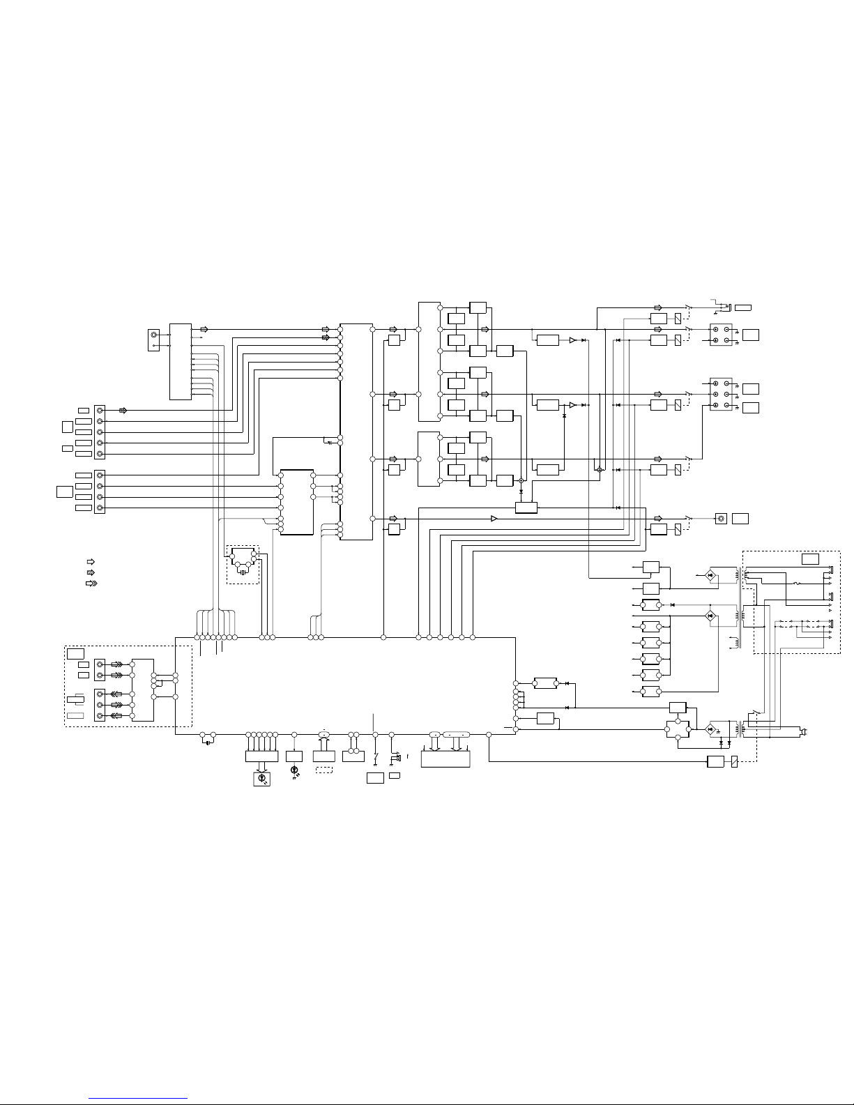
SECTION 3
DIAGRAMS
3-1. BLOCK DIAGRAM
TUNER UNIT
RESET
Q201,202
Q659
: VIDEO
• Signal Path
• RCH is omitted
: FM
: CD
FM
AM
R-CH
S DATA
PLL DATA
S CLK
S CE
SIGNAL
STEREO
AUTO STOP
T MUTE
S DATA
DATA OUT
S CLK
SLAT
SIGNAL
STEREO
TUNED
T MUTE
FM
AM DET OUT
R OUT
L OUT
MD/
TAPE
CD
OUTPUT
INPUT
OUTPUT
INPUT
VIDEO
5.1
CH/DVD
FRONT
REAR
CENTER
WOOFER
J501
J401
LT IN
61
FC L IN
34
FC SL IN
32
FC C IN
62
DATA
52
DOLBY
SURROUND PROCESSOR
IC202
16L OUT
CLK
53
ENABLE
51
2
18SL OUT
10C OUT
DATA
CLK
4
14
16
13
X1
4.33MHz
RDS
IC1
AEP,UK,Russian,
East European MODEL
AUDIO SELECT
IC201
IN F2
66
IN A2
71
REC OUT 2A
61
IN B2
70
IN G2
63
SW CH N IN
27
D OUT2
59
49
L OUT
REC OUT 2B
61
43SL OUT
37
C OUT
28
SW CH OUT
MUTE
Q361
SEL OUT2
60
T IN2
58
SL CH N IN
44
DATA
32
CLOCK
31
LATCH
33
SL CH D IN
45
C CH N IN
38
C CH D IN
39
DATA
CLOCK
S CE
MUTE
Q362
MUTE
Q363
MUTE
Q364
IN1
6
2
+V OUT1
POWER AMP
IC701
5
NF1
LIMITER
Q701
3
-V OUT1
LIMITER
Q702
BOOSTER
Q703
BOOSTER
Q704
CURRENT
DETECT
Q705,706
OVER LOAD
DETECT
Q708,709
IN2
8
12
+V OUT2
9NF2
LIMITER
Q651
11
-V OUT1
LIMITER
Q652
BOOSTER
Q653
BOOSTER
Q654
CURRENT
DETECT
Q655,656
IN+
1
6
+V OUT
POWER AMP
IC501
2
IN-
LIMITER
Q501
5-V OUT
LIMITER
Q502
BOOSTER
Q503
BOOSTER
Q504
CURRENT
DETECT
Q505,506
OVER LOAD
DETECT
Q507,509
OVER LOAD
DETECT
Q657,658
Q707
D706
D606
D506
D721
PROTECT
SWITCH
Q722,723,725
RELAY
DRIVE
Q791
RY791
RELAY
DRIVE
Q730
RY710
D731
RELAY
DRIVE
Q610
RY610
D735
RELAY
DRIVE
Q550
RY510
D734
IC401
3
1
RELAY
DRIVE
Q470
RY470
D736
L
R
SR
SL
C
R-CH
R-CH
R-CH
SPEAKERS
FRONT
PHONES
SPEAKERS
REAR
SPEAKERS
CENTER
TM601
TM602
SUB
WOOFER
J403
5.1CH
(VIDEO IN)
TV/LD
5.1 IN
J281
IN
OUT
OUT
J282
VIDEO1
MONITOR
DE345 MODEL
V3
12
V1
1
OUT
5
V2
3
M OUT
10
13S1
2S2
4S2
11
M
VIDEO SELECT
IC281
21
AUTO STOP
S1
2
S2
3
IC MUTE
4
22
T MUTE
23
STEREO IN
28
SIGNAL
24
PLL DATA
19
S DATA
18
S CLK
20
S CE
38
RDS CLK
15
RDS DATA
8
S CLK
9
S CE
17
S CE
7
S DATA
59
FUNC MUTE
47
PROTECT
AUTO STOP
T MUTE
STEREO
SIGNAL
PLL DATA
S DATA
S CLK
S CE
CLOCK
S CE
DATA
54
H/P RY
53
FRONT RY
51
REAR RY
52
CTR RY
55
WOOFER RY
100 9133 30
A/D1 A/D4
FUNCTION
KEY
S206-235
S236,237
CE MODEL ONLY
LED DRIVE
Q126
MUTING LED
45
S FIELD LED68B.B LED
69
SURR LED66LEVEL LED
65
NAME LED
64
SETUP LED
63
LED DRIVE
Q210-215
D216
MUTING
D210-215
SYSTEM CONTROL
IC103
RV201
ENCODER
2 3
ENCODER50ENCODER49SYS POWER
56
SP SW
61
SYSTEM
POWER
S200SPS201
ON
OFF
90 80 78 75
.
DIG1-10 S1-S15
FLUORESCENT
INDICATOR TUBE
F1 F2
FL201
10
RESET
39
STOP
26
SIRCS
REMOTE
CONTROL
RECEIVER
2
1
IC203
POWER
CONTROL
IC950
5
8
3
6
+5.6V REG
Q951
D201
D202
D910-913
AC
IN
T972
RY901
D915D914
RELAY
DRIVE
Q470
D820-823
46
VDD
34
VDD
16
VDD
1VDD
-7V
REG
3 2
+7V
REG
3 1
+5V
REG
3 1
+5V
REG
3 1
+9V
REG
3 1
DOLBY SURR
+9V
DISPLAY
+5V(A)
AUDIO
+7V
AUDIO
-7V
TUNER,RDS
AUDIO
+5V(B)
IC805
IC803
IC804
IC807
IC802
POWER RY
48
RELAY
+B
+12V
REG
3 1
POWER AMP
+12V
IC801
-24V REG
Q801
FL201
-24V
-B SW
Q715
POWER AMP
-B
D824
D802
T901
POWER AMP
+B
240V
220V
120V
0V
VOLTAGE
SELECTOR
E,Saudi Arabia,PX MODEL
S901
12 11
X1
X2
X201
5.00MHz
16
F1
F2

88
3-2. IC BLOCK DIAGRAMS
IC281 NJM2279 (VIDEO BOARD)
VIN3
V-
14
SW213VIN112MUTE111VOUT110NC9V+
8
1
SW1
2
AMP
VIN2
3
MUTE2
4
VOUT2
5
GND26GND1
7
AMP
IC701, IC702 uPC2581V (MAIN BOARD)
PROTECTOR
DRIVE
1
2
3 456 7 8 9 10 11 12 13 14 15
PRE
DRIVE
PRE
DRIVE
BIAS CIRCUIT
REG
MUTE
+VOUT1
–VOUT1
COMP1
NF1
IN1
GND
IN2
NF2
COMP2
–VOUT2
+VOUT2
VCC1
VCC2
VEE
DRIVE
IC501 STK350-230 (MAIN BOARD)
1
2
3
4
5
6
7
8
9
TR3 R1
R2
TR4
TR6
TR7
R4
R9
TR5
TR1
TR2
R6
D4 D3
R7
R8
TR8
D1 D2
R5
R3
INPUT
NF
-VEOUT
+VEOUT
V
SS
GND
V
CC
SUB
IC1 BU1924 (MAIN BAORD)
1 2 3 4 5 6 7 8
910111213141516
QUAL
RDATA
VREF
VDD1
VSS1
MUX
VSS3
CMP
RCLK
XOXI(NC)
VDD2
VSS2
T1
T2
8TH SWITCHED
CAPACITOR
FILTER
PLL 57KHz
RDS/ARI
BIPHASE
DECODER
DEFFERENTIAL
DECODER
PLL
1187.5Hz
TEST
CLOCK
IC950 NJM2103 (POWER BOARD)
1
2
3
4
5
6
7
8
V+
VSB/SESIN
VSA
RESET
GND
OUTC
VSC
CR
VREF
+
–
–
+
–+–
+
Q
R S
3-3. IC PIN FUNCTION DESCRIPTION
IC103 µPD780205GF (DISPLAY BOARD)
Pin No.
1
2
3
4
5
6
7
8
9
10
11
12
13
14
15
16
17
18
19
20
21
22
23
24
25
26
27
28
29
30
31
32
33
34
35
36
37
38
39
40
41
42
43
44
45
46
47
48
49
50
I/O
I
O
O
O
—
—
O
O
O
I
—
—
—
—
I
—
O
O
O
O
I
O
I
I
—
I
—
I
I
I
I
I
I
—
—
—
—
I
I
—
—
—
—
—
O
—
I
O
I
I
Description
Power supply to µ-com
Control Video IC switching
Control Video IC switching
Control mute of Video IC
Volume IC data
Volume IC clock
Volume IC enable
Read µ-com reset signal
For µ-com clock
Programming pow. supply
No use
Read decoded RDS data
Power supply to µ-com
Chip enable for ICs
Output clock signal
Output data signal
Chip enable for ICs
Tuner has tuned to a freq.
Mute tuner during scanning
Tuned freq. has stereo
Input tuner freq. data
Analog ground
Read remote comm. signal
Detect RDS signal level
Read version setting
Read key push signal
Read key push signal
Read key push signal
Read key push signal
Analog Power Supply
Analog reference ground
Read decoded RDS clock
Read signal when AC off
µ-com ground
Control mute LED
Power supply to µ-com
Detect Protector Status
Control Power relay
Read volume encoder changing
Read volume encoder changing
Pin Name
VDD +5V
S1
S2
IC.MUTE
P34
P33
S.DATA (M61501FP)
S.CLK (M61501FP)
S.CE (M61501FP)
RESET
X2
X1
VSS
—
RDS.DATA.IN
VDD +5V
S.CE (LV1050M)
S.CLK(DOLBY.TUNER)
S.DA TA(DOLBY.TUNER)
S.CE (TUNER)
AUTO-STOP
T.MUTE
STEREO-IN
PLL.DATA
AVSS
SIRCS
P16
SIGNAL
VERSION
A/D IV
A/D III
A/D II
A/D I
AVDD +5.0V
AVREF
P03
P02
RDS.CLK.IN
STOP
VSS
P74
P73
P72
P71
MUTING LED
VDD +5.0V
PROTECT
POWER-RY
ENCODER
ENCODER
99
For schematic diagrams.
Note:
• All capacitors are in µF unless otherwise noted. pF: µµF
50 WV or less are not indicated except for electrolytics
and tantalums.
• All resistors are in Ω and 1/
4
W or less unless otherwise
specified.
• % : indicates tolerance.
• f : internal component.
• 2 : nonflammable resistor.
• 1 : fusible resistor.
• C : panel designation.
• U : B+ Line.
• V : B– Line.
• H : adjustment for repair.
• Voltages and waveforms are dc with respect to ground
under no-signal (detuned) conditions.
No mark : FM
• Voltages are taken with a VOM (Input impedance 10 M Ω).
Voltage variations may be noted due to normal production
tolerances.
• Waveforms are taken with a oscilloscope.
• Circled numbers refer to waveforms.
• Signal path.
F : FM
J : CD
g : VIDEO
I : PHONO
• Abbreviation
CND : Canadian model.
AUS : Australian model.
SP : Singapore model.
MY : Malaysia model.
AR : Argentine model.
CH : Chinese model.
MX : Mexican model.
CIS : Russian model.
EA : Saudi Arabia model.
EE : East European model.
THIS NOTE IS COMMON FOR PRINTED WIRING
BOARDS AND SCHEMATIC DIAGRAMS.
(In addition to this necessary note is printed in each
block.)
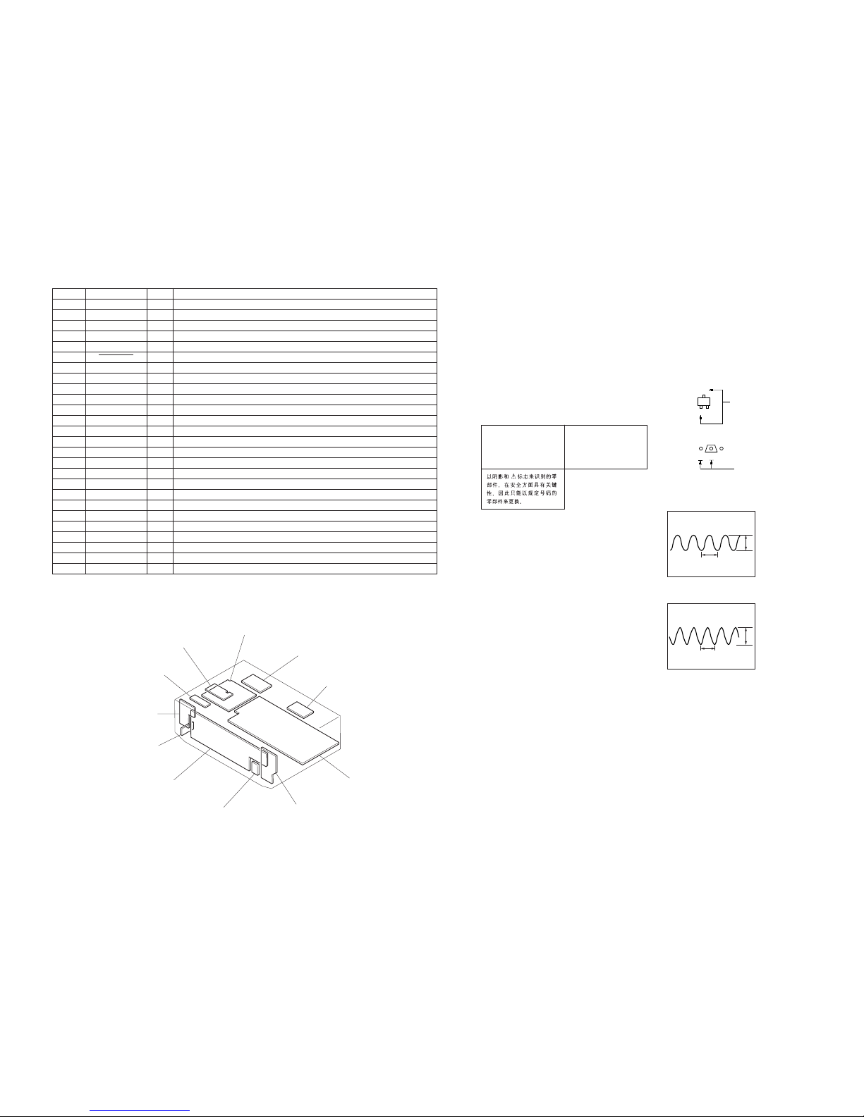
Note:
The components identified by
mark ! or dotted line with mark
! are critical for safety.
Replace only with part number
specified.
Note:
Les composants identifiés par
une marque ! sont critiques
pour la sécurité.
Ne les remplacer que par une
pièce portant le numéro spécifié.
• Waveform
– MAIN SECTION –
– PANEL SECTION –
For printed wiring boards.
Note:
• X : parts extracted from the component side.
• a : Through hole.
• f : internal component.
• b : Pattern from the side which enables seeing.
C
B
These are omitted.
E
Q
B
These are omitted.
CE
3-4. CIRCUIT BOARDS LOCATION
Pin No.
51
52
53
54
55
56
57
58
59
60
61
62
63
64
65
66
67
68
69
70
71 – 74
75 – 78
79
80 – 84
85 – 90
91 – 100
Pin Name
REAR-RY
CTR-RY
FRONT-RY
H/P-RY
WOOFER RY
SYS.POWER
P115
P114
FUNC.MUTE
P112
SP SW
P110
SET UP LED
NAME LED
LEVEL LED
SURR LED
P103
S.FIELD LED
B.B. LED
P100
P97 – P94
S15 – S12
VLOAD
S11 – S7
S6 – S1
DIG10 – DIG1
Description
Control rear relay on/off
Control center relay
Control speaker relay
Control Headphone relay
Control Woofer relay
Detect power switch key
Control muting circuit
Read speaker switch comdition
Control Setup LED
Control Name LED
Control LEVEL LED
Control SURR LED
Control SF LED
Control Bass Boost LED
Output signal to FL tube
Negative power supply
Output signal to FL tube
Output signal to FL tube
I/O
O
O
O
O
O
I
—
—
O
—
I
—
O
O
O
O
—
O
O
—
—
O
I
—
O
O
STANDBY board
POWER SWITCH board
HEADPHONE board
DISPLAY board
ENCODER board
TUNING board
MAIN boar
d
VIDEO board
SECONDARY board
PRIMARY board
VOL-SEL board
1
IC1 qf
2.2Vp-p
230ns
2
IC103 qa
5.0Vp-p
200ns
STR-DE245/DE345
1010
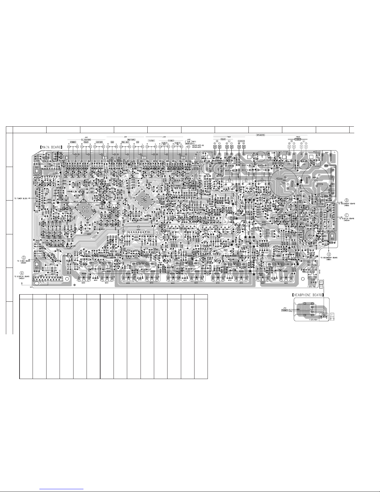
3-5. PRINTED WIRING BOARD MAIN SECTION
• Refer to page 9 for Circuit Boards Location.
12
A
B
C
D
E
F
345678910
(Page 16)
(Page 14)
(Page 16)
(Page 18)
(Page 14)
CIS, EE
CIS, EE
C706
C606
C764
C714
Ref. No. LocationRef. No. Location
• Semiconductor Location
D470 B-6
D505 D-3
D506 D-4
D508 D-3
D510 B-8
D605 D-6
D606 C-6
D607 D-6
D608 D-6
D610 B-7
D627 D-9
D706 D-5
D710 B-8
D721 C-9
D722 B-8
D725 D-8
D726 D-8
D727 D-4
D728 D-4
D731 B-8
D732 B-8
D734 B-8
D735 B-7
D736 B-6
D757 D-7
D791 D-9
D801 C-10
D802 B-10
D804 C-10
D820 C-9
D821 C-10
D822 C-10
D823 C-9
D824 B-9
D825 B-10
IC1 B-2
IC201 B-4
IC202 C-3
IC401 B-5
IC501 C-4
IC701 C-6
IC702 C-7
IC801 C-8
IC802 C-9
IC803 C-9
IC804 C-9
IC805 A-2
IC807 B-6
Q361 B-5
Q362 B-6
Q363 B-6
Q364 B-7
Q365 C-6
Q366 C-6
Q470 B-6
Q501 D-2
Q502 E-3
Q503 E-3
Q504 E-3
Q505 D-2
Q506 D-2
Q507 D-3
Q509 D-3
Q550 B-7
Q601 D-8
Q602 E-8
Q603 E-8
Q604 E-9
Q605 D-9
Q606 D-8
Q610 B-7
Q651 D-5
Q652 E-6
Q653 E-5
Q654 E-6
Q655 D-5
Q656 D-6
Q657 D-6
Q658 D-6
Q659 D-6
Q701 D-4
Q702 E-4
Q703 E-4
Q704 E-5
Q705 D-5
Q706 D-4
Q707 D-5
Q708 D-5
Q709 D-5
Q715 C-8
Q722 B-9
Q723 C-8
Q725 B-8
Q730 B-8
Q751 D-7
Q752 E-7
Q753 E-7
Q754 E-7
Q755 D-7
Q756 D-7
Q757 D-7
Q758 D-7
Q759 D-8
Q791 D-9
Q801 D-9
IC3505 G-11
IC3506 I-10
IC3507 I-11
IC3508 H-10
IC3509 H-11
IC3510 J-10
IC3511 J-11
IC3512 J-10
IC3513 J-11
IC3514 I-11
IC3515 J-11
IC3516 I-12
IC3517 J-12
Q3301 G-3
Q3302 G-3
Q3303 G-4
Q3304 G-3
Q3305 G-3
Q3306 H-3
Q3307 G-6
Q3308 B-11
Q3309 H-5
Q3310 D-12
Q3311 H-5
Q3312 D-12
Q3313 H-5
Q3314 D-12
Q3315 G-5
Q3401 G-8
Q3402 H-8
Q3403 H-7
Q3404 H-7
Q3405 H-7
Q3406 G-6
Q3407 D-4
Q3501 H-12
Q3502 H-12
Q3503 H-12
Q3504 G-12
Q3505 G-12
Q3506 G-12
Q3511 G-11
Q3512 H-11
Q3513 G-11
Q3514 G-11
Q3515 I-11
Q3516 I-11
Q3517 H-11
Q3518 H-11
Q3519 J-11
Q3520 J-11
Q3521 J-11
Q3522 J-11
Ref. No. Location Ref. No. Location Ref. No. Location Ref. No. Location Ref. No. Location
 Loading...