

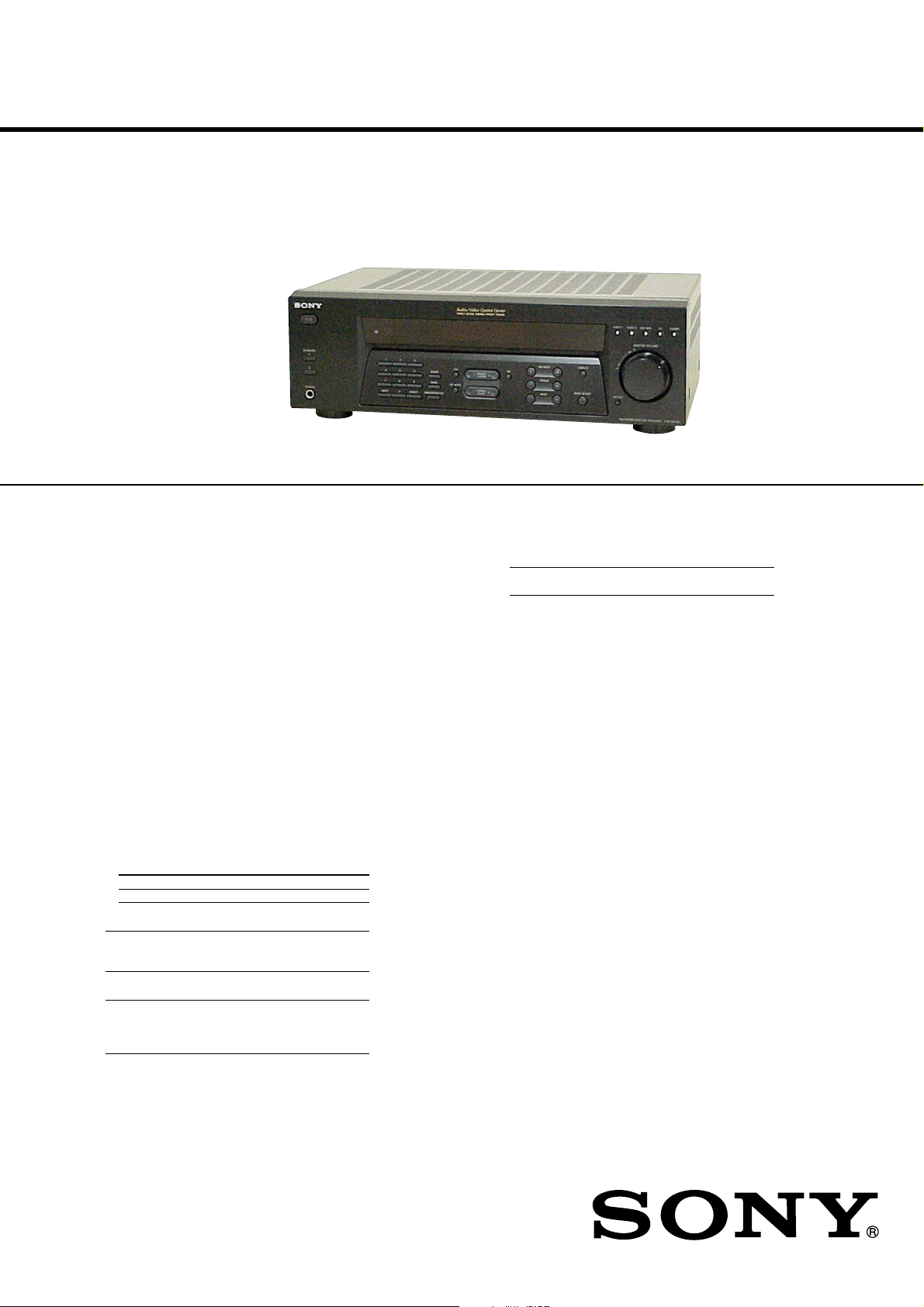
STR-DE185
SERVICE MANUAL
Ver 1.1 2003. 11
SPECIFICATIONS
AUDIO POWER SPECIFICATIONS
POWER OUTPUT AND TOT AL
HARMONIC DISTORTION:
With 8 ohm loads, both channels driven, from
40 – 20,000 Hz; rated 100 watts per channel
minimum RMS power, with no more than
0.09 % total harmonic distortion from 250
milliwatts to rated output (Models of area code
US only).
Amplifier section
POWER OUTPUT
Models of area code US
Rated Power Output at Stereo Mode
(8 ohms 40 Hz – 20 kHz, THD 0.09 %)
Models of area code AEP, UK
Rated Power Output at Stereo Mode
8 ohms 1 kHz, THD 0.7 %)
(
1) Measured under the following conditions:
Area code Power requirements
AEP, UK 230 V AC, 50 Hz
100 W + 100 W
100 W + 100 W
1)
US Model
AEP Model
UK Model
Outputs
MD/TAPE, VIDEO 1 Voltage: 250 mV
Impedance: 10 kilohms
Bass Boost: +8 dB at 70 Hz
Tone: ±10 dB at 100 Hz and
10 kHz
FM tuner section
Tuning range 87.5 – 108.0 MHz
Antenna terminals 75 ohms, unbalanced
Intermediate frequency 10.7 MHz
Sensitivity
Mono: 18.3 dBf, 2.2 µV/75 ohms
Stereo: 38.3 dBf, 22.5 µV/75 ohms
Usable sensitivity 11.2 dBf, 1 µV/75 ohms
S/N
Mono: 76 dB
Stereo: 70 dB
Harmonic distortion at 1 kHz
Mono: 0.5%
Stereo: 0.8%
Separation 35 dB at 1 kHz
Frequency response 30 Hz – 15 kHz,
+0.5/–2 dB
Selectivity 60 dB at 400 kHz
Frequency response
CD, MD/TAPE, 20 Hz – 50 kHz
VIDEO 1, VIDEO 2 +0/–0.5 dB (with bass
Inputs (Analog)
CD, MD/TAPE, Sensitivity: 250 mV
VIDEO 1, VIDEO 2 Impedance: 50 kilohms
2) INPUT SHORT.
3) Weighted network, input level.
9-873-586-02
2003K04-1
© 2003.11
boost bypassed)
2)
S/N
: 85 dB
(A, 250 mV
3)
)
Sony Corporation
Home Audio Company
Published by Sony Engineering Corporation
– Continued on next page –
FM STEREO/FM-AM RECEIVER
1
STR-DE185
AM tuner section
Tuning range
Models of area code US
With 10-kHz tuning scale: 530 – 1710 kHz
With 9-kHz tuning scale: 531 – 1710 kHz
Models of area code AEP, UK
With 9-kHz tuning scale: 531 – 1602 kHz
Antenna Loop antenna
Intermediate frequency 450 kHz
Usable sensitivity 50 dB/m (at 1,000 kHz or
999 kHz)
S/N 45 dB (at 50 mV/m)
Harmonic distortion 1.0 % (50 mV/m,
400 Hz)
Selectivity
At 9 kHz: 35 dB
At 10 kHz: 40 dB
4) You can change the AM tuning scale to 9 kHz or
10 kHz. After tuning in any AM station, turn off
the receiver. Hold down PRESET TUNING + and
press ?/1. All preset stations will be erased when
you change the tuning scale. To reset the scale to
10 kHz (or 9 kHz), repeat the procedure.
4)
4)
General
Power requirements
Area code Power consumption
US 120 V AC, 60 Hz
AEP, UK 230 V AC, 50/60 Hz
Power consumption
Area code Power consumption
US 190 W
AEP, UK 210 W
Power consumption (during standby mode)
0.5 W (for models of all area code)
AC outlets
Area code AC outlets
US 1 switched, 120 W/1A MAX
AEP, UK 1 switched, 100 W MAX
Dimensions 430 × 145 × 300 mm
Mass (Approx.) 7.0 kg (15 lb 7 oz)
Supplied accessories
FM wire antenna (1)
AM loop antenna (1)
Remote commander RM-U185 (1)
R6 (size-AA) batteries (2)
Design and specifications are subject to change without
notice.
(16 7/8 × 5 6/8 × 11 6/8 in.)
including projecting parts
and controls
MODEL IDENTIFICATION
— BACK PANEL —
Part No.
MODEL PART No.
US 4-238-277-0s
AEP 4-238-277-1s
UK 4-238-277-2s
SAFETY-RELATED COMPONENT WARNING!!
COMPONENTS IDENTIFIED BY MARK 0 OR DOTTED LINE
WITH MARK 0 ON THE SCHEMATIC DIAGRAMS AND IN
THE PARTS LIST ARE CRITICAL TO SAFE OPERATION.
REPLACE THESE COMPONENTS WITH SONY PARTS WHOSE
PART NUMBERS APPEAR AS SHOWN IN THIS MANUAL OR
IN SUPPLEMENTS PUBLISHED BY SONY.
2
STR-DE185
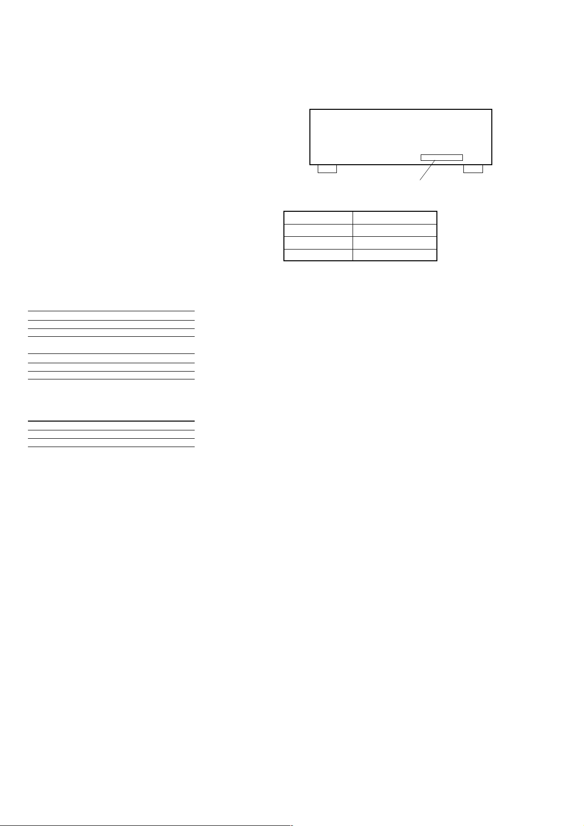
SAFETY CHECK-OUT
After correcting the original service problem, perform the following
safety check before releasing the set to the customer:
Check the antenna terminals, metal trim, “metallized” knobs, screws,
and all other exposed metal parts for AC leakage. Check leakage as
described below.
LEAKAGE TEST
The AC leakage from any exposed metal part to earth ground and
from all exposed metal parts to any exposed metal part having a
return to chassis, must not exceed 0.5 mA (500 microamperes).
Leakage current can be measured by any one of three methods.
1. A commercial leakage tester, such as the Simpson 229 or RCA
WT-540A. Follow the manufacturers’ instructions to use these
instruments.
2. A battery-operated AC milliammeter. The Data Precision 245
digital multimeter is suitable for this job.
3. Measuring the voltage drop across a resistor by means of a VOM
or battery-operated AC voltmeter. The “limit” indication is 0.75
V, so analog meters must have an accurate low-voltage scale. The
Simpson 250 and Sanwa SH-63Trd are examples of a passive
VOM that is suitable. Nearly all battery operated digital
multimeters that have a 2V AC range are suitable. (See Fig. A)
To Exposed Metal
Parts on Set
TABLE OF CONTENTS
1. GENERAL
Main unit ................................................................................. 4
Remote button description ....................................................... 5
2. DISASSEMBLY
2-1. Case ..................................................................................... 6
2-2. Front Panel Section ............................................................. 7
2-3. Back Panel ........................................................................... 7
2-4. Main Board ......................................................................... 8
3. TEST MODE ........................................................................ 9
4. DIAGRAMS
4-1. IC Pin Description ............................................................. 10
4-2. Circuit Boards Location .................................................... 11
4-3. Block Diagram – Main Section – ...................................... 12
4-4. Block Diagram – Power Section – .................................... 13
4-5. Printed Wiring Board – Main Section – ............................ 14
4-6. Printed Wiring Boards – H/P, Outlet Section – ................. 15
4-7. Schematic Diagram – Main Section (1/2) – ...................... 16
4-8. Schematic Diagram – Main Section (2/2) – ...................... 17
4-9. Schematic Diagram – Display Section – ........................... 18
4-10. Printed Wiring Board – Display Section – ........................ 19
4-11. Printed Wiring Board – Power SW Section – ................... 20
5. EXPLODED VIEWS
5-1. Case Section ...................................................................... 21
5-2. Front Panel Section ........................................................... 22
5-3. Chassis Section ................................................................. 23
6. ELECTRICAL PARTS LIST......................................... 24
0.15 µF
1.5 k
Ω
Earth Ground
AC
voltmeter
(0.75 V)
Fig. A. Using an AC voltmeter to check AC leakage.
3
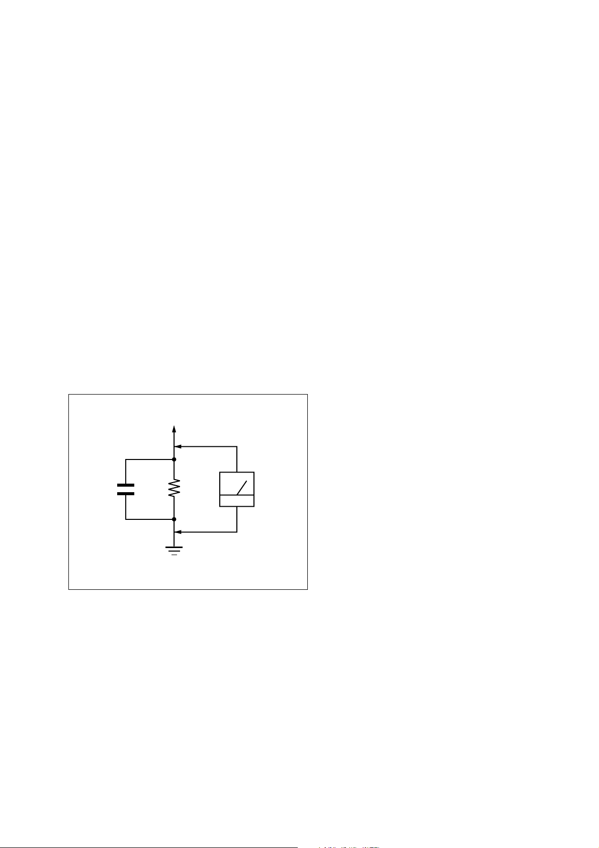
STR-DE185
SECTION 1
GENERAL
List of Button Locations and Reference Pages
This section is extracted
from instruction manual.
How to use this page
Use this page to find the location of buttons that are
mentioned in the text.
Main unit
ALPHABETICAL ORDER
A – H
AM 8 (13, 14)
BALANCE L/R q; (12)
BASS +/– wa (12)
BASS BOOST ql (12)
CD qg (8, 12)
DIRECT wg (13)
DISPLAY qa (12, 16)
Display 9 (11-16, 18, 19)
FM 6 (13, 14)
FM MODE wd (14)
I – O
IR (receptor) 2 (4, 22)
1 2 3 456 7 8 9q; qa qsqd qf qgqh
MASTER VOLUME qj (12, 20)
MD/TAPE qf (8, 12)
MEMORY/ENTER wf (13, 15,
18)
MUTING qk (12, 20)
NAME 5 (18)
Numeric buttons 3 (13)
P – S
PHONES wl (12, 21)
PRESET/PTY SELECT +/–
(models of area code CEL,
CEK) 7 (15, 16)
PRESET TUNING +/– (models of
area code U) 7 (15, 23)
PTY (models of area code CEL,
CEK) 4
(16)
Illustration number
r
List of Button
NAME 5 (18)
Name of button/part Reference page
RR
Locations and
SHIFT wh (15)
SLEEP (models of area code U)
4 (19)
SPEAKERS A wj (10, 12)
SPEAKERS B wk (10, 12)
Reference Pages
T – Z
TREBLE +/– w; (12)
TUNER qh (8, 12-15, 18)
TUNING/CHAR +/– ws (14, 18)
VIDEO 1 qs (12)
VIDEO 2 qd (8, 12)
BUTTON DESCRIPTIONS
?/1 (power) 1 (11, 13, 23)
wl
qjqkqlw;wawswdwfwgwhwjwk
GB
5
4
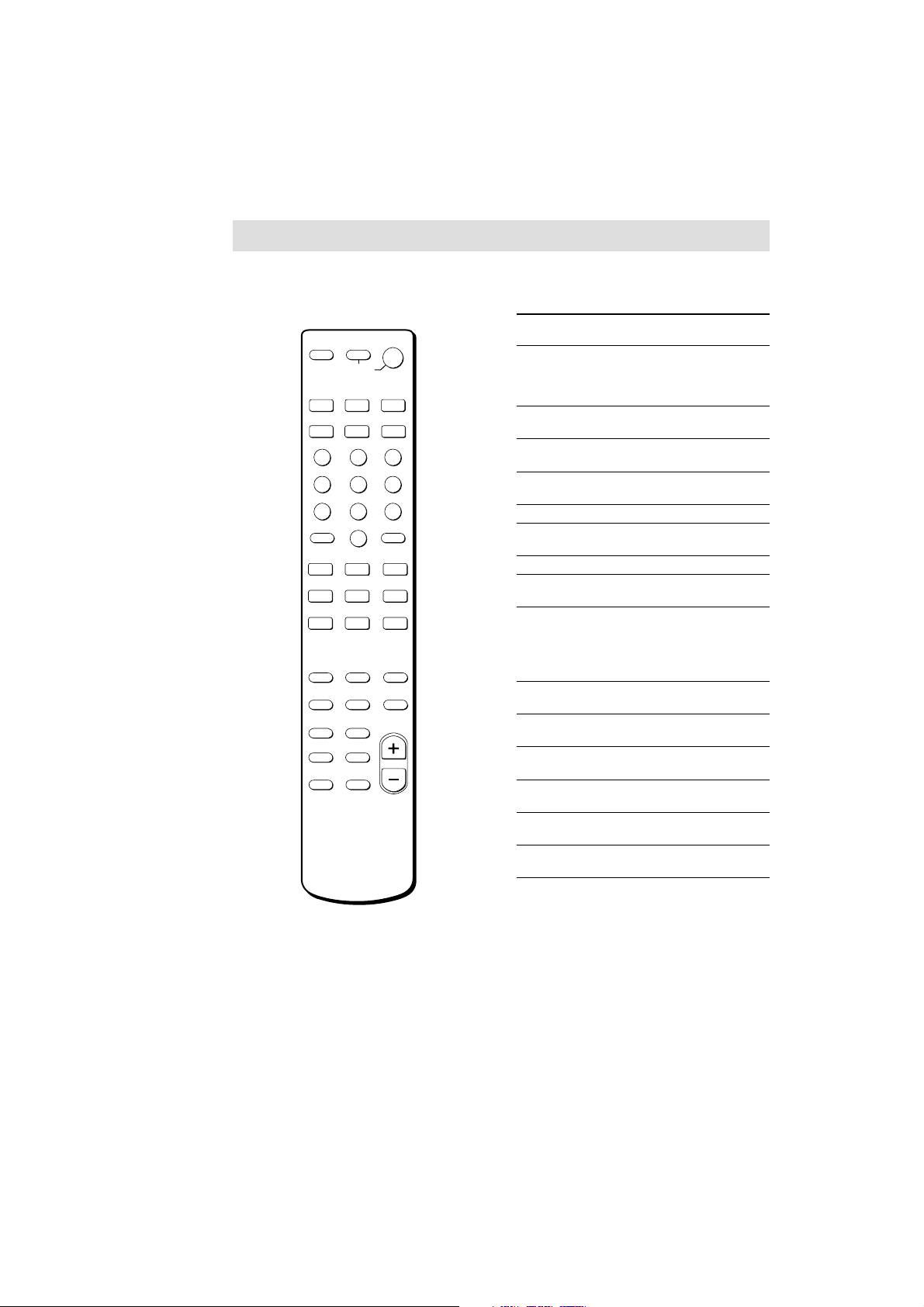
Remote button description
STR-DE185
You can use the remote RM-U185 to operate
the components in your system.
SYSTEM
STANDBY
VIDEO 2
CD
F
ENTER
f
?/1
DVD
TUNER
•
g
O
SLEEPAV?/1
VIDEO 1
MD/TAPE
TOP MENU DVD MENU
123
G
456
78 9
0
+
>
M
X
+
+
++
TV CH
––
D. TUNING
ENTER
RETURN
TV/VIDEO
ANT
TV/VTR
D.SKIP
x
BASS BOOST
MUTING
MASTER
VOL
SHIFT
>10
– /– –
–
CH/PRESET
.
m
N
L BALANCE R
–
TREBLE
–
BASS
TV VOL
The tables below show the settings of each
button.
Remote Operations Function
Button
SLEEP Receiver Activates the sleep
?/1 Receiver Turns the receiver on or
VIDEO 1 Receiver To watch VCR.
VIDEO 2 Receiver To watch VCR.
DVD Receiver To watch DVD.
MD/TAPE
Receiver To listen to Minidisc or
CD Receiver To listen to compact disc.
TUNER Receiver To listen to radio
SHIFT Receiver Press repeatedly to select
D.TUNING
BALANCE
Receiver Tuner station direct
Receiver Adjust the balance.
L/R
BASS Receiver Reinforce the bass.
BOOST
TREBLE Receiver Adjust the treble tone
+/– quality.
MUTING Receiver Mutes the sound from the
BASS +/– Receiver Adjust the bass tone
function and the duration
which the receiver turns
off automatically.
off.
(VTR mode 3)
(VTR mode 1)
audio tape.
programs.
a memory page for
presetting radio stations
or tuning to preset
stations.
key-in-mode.
receiver.
quality.
24
Note
When you press the function buttons (VIDEO 1,
VIDEO 2, DVD), the input mode of the TV might not
switch to the corresponding input mode that you
want. In this case, press the TV/VIDEO button to
switch the input mode of the TV.
GB
5
STR-DE185
e
SECTION 2
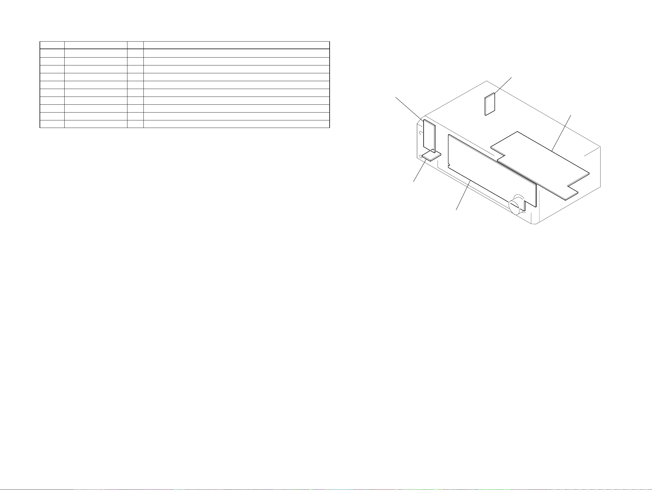
DISASSEMBLY
Note : This set can be disassemble according to the following sequence.
SET
2-1. CASE
(Page 6)
2-2. FRONT PANEL SECTION
(Page 7)
Note : Follow the disassembly procedure in the numerical order given.
2-3. BACK PANEL
(Page 7)
2-1. CASE
1
two screws
(case 3 TP2)
2-4. MAIN BOARD
(Page 8)
2
two screws
(case 3 TP2)
4
cas
3
two screws
(case 3 TP2)
6
2-2. FRONT PANEL SECTION
3
CNP801
4
two screws
(BVTP3 x 8)
2
STR-DE185
CN5
6
front panel section
2-3. BACK PANEL
3
CNP907
2
CNP901
5
9
back panel (DE1)
8
1
CN4
four screws
(BVTP3 x 8)
screw
(BVTP3 x 8)
4
three screws
(BVTP3 x 8)
5
two screws
(BVTP3 x 8)
6
two screws
(BVTP3 x 8)
1
CN3
7
screw
(BVTP3 x 8)
7
STR-DE185
2-4. MAIN BOARD
two screws
3
(BVTP3 x 8)
6
screw
(BVTP3 x 8)
2
CNP905
1
CNP904
4
two screws
(BVTP3 x 8)
5
screw
(BVTP3 x 8)
8
MAIN board
7
8
SECTION 3
f
TEST MODE
Fluorescent Indicator Tube Test Mode
All fluorescent segments are tested. When this test is activated, all
segments turn on at the same time, then each segment turns on one
after another.
Procedure:
1. While pressing the five function buttons of [VIDEO 1], [VIDEO 2],
[MD/TAPE], [CD] and [TUNER] simultaneously, press the ?/1
button to turn the power ON.
2. The FL tube will illuminate in half light on. The following display will be repeated whenever the five function buttons are
pressed.
• Operation of function buttons
all light on half light on 1 half light on 2 all light of
3. Press any button other than the function buttons to release the
check mode.
AUTO-BETICAL Check Mode (AEP, UK models)
To auto-scanning and memories of RDS station.
Procedure:
1. While pressing the [MEMORY/ENTER] button, press the
button to turn the power ON.
2. The message “AUTO-BETICAL SELECT” are scrolled.
?/1
STR-DE185
AM Tuning Interval Selection Mode (US model)
Either 9 kHz step or 10 kHz step can be selected for the AM tuning
interval.
Procedure:
1. While pressing the [TUNING/CHAR +] button, press the ?/1
button to turn the power ON.
2. Either the message “9k STEP” or “10k STEP” appears.
3. Select the desired step.
Software Version Display Mode
The software version is displayed.
Procedure:
1. While pressing the two buttons of [SPEAKERS B] and [VIDEO 1]
simultaneously, press the ?/1 button to turn the power ON.
2. The software version is displayed.
ex.) US model : U
AEP, UK model : CE *.
*.**
**
Shift version
Area
9

STR-DE185
SECTION 4
DIAGRAMS
4-1. IC PIN DESCRIPTION
• IC201 µPD78044FGF-200-3B9 (SYSTEM CONTROLLER, FL DRIVER)
Pin No. Pin Name I/O Pin Description
1 to 7 DIG7 to 1 O Digit drive signal output to the fluorescent indicator tube (FL201).
8 +5V — Power supply pin (+5 V)
9 CL O Serial clock signal output to FM/AM tuner pack.
10 DO O Serial data signal output to FM/AM tuner pack.
11 DI I Serial data signal input from FM/AM tuner pack.
12 CE O Serial chip enable signal output to FM/AM tuner pack.
13 VOL DATA O Serial data signal output to sound control IC.
14 VOL CE O Serial clock signal output to sound control IC.
15 RDS DATA I RDS data signal input from FM/AM tuner pack. (AEP, UK model only)
16 PROTECTOR I Overload detection signal input
17 RESET I Reset signal input
18 TUNED I TUNED indicator detection signal input from FM/AM tuner pack.
19 STEREO I STEREO indicator detection signal input from FM/AM tuner pack.
20 AVSS — Analog ground
21 VERSION I Destination select signal input (Fixed at H: US model, L: AEP, UK model)
22 FM SIGNAL OUT I
23 to 28 AD6 to 1 I Function keys signal input
29 AVDD — A/D converter power supply pin (+5 V)
30 AVREF — A/D converter reference voltage input (+5 V)
31 NC — Not used. (Connect to AVREF pin in this set)
32 OPEN — Not used. (Open)
33 GND — Ground
34 X1 I Master clock input (4.19 MHz)
35 X2 O Master clock output (4.19 MHz)
36 REC SW1 O VIDEO 1 ON/OFF signal output
37 REC SW2 O MD/TAPE ON/OFF signal output
38, 39 VOL A, B I Master volume JOG data input A, B
40 FUNC.MUTE O Not used. (Fixed at L in this set)
41 CK O Serial clock signal output to electoric volume IC.
42 DATA O Serial data signal output to electoric volume IC.
43 STB O Serial data strobe signal output to electoric volume IC.
44 SYS.POWER I System power signal input
45 AC MUTE O A-Class mute signal output
46 RDS INT I RDS clock signal input from FM/AM tuner pack. (AEP, UK model only)
47 STOP I Stop signal input from reset signal generator IC.
48 VSS — Ground
49 SIRCS I Sircs signal input from remote control receiver IC.
50 TUNER MUTE O Muting control signal output to FM/AM tuner pack.
51 NC — Not used. (Open)
52 +5V — Power supply pin (+5 V)
53 BASS B. LED O BASS BOOST LED drive signal output
54 SPK A LED O SPEAKERS A LED drive signal output
55 SPK B LED O SPEAKERS B LED drive signal output
FM/AM signal meter voltage detection signal input from FM/AM tuner pack.
(AEP, UK model only)
10
STR-DE185
Pin No. Pin Name I/O Pin Description
56 RY R1 COIL O Power relay (12V) drive signal output
57 RY POWER O AC power relay (9V) drive signal output
58 RY A O Speakers A relay (12V) drive signal output
59 RY B O Speakers B relay (12V) drive signal output
60 RY HP O Phones relay (12V) drive signal output
61 NC — Not used. (Open)
62 to 70 S15 to 7 O Segment drive signal output to the fluorescent indicator tube (FL201).
71 VLOAD — Power supply pin (-24 V)
72 to 77 S6 to 1 O Segment drive signal output to the fluorescent indicator tube (FL201).
78 to 80 DIG10 to 8 O Digit drive signal output to the fluorescent indicator tube (FL201).
4-2. CIRCUIT BOARDS LOCATION
OUTLET board
POWER SW board
MAIN board
HP board
DISPLAY board
11 11
STR-DE185
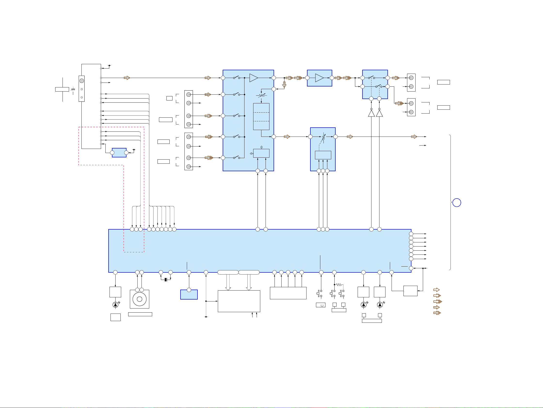
4-3. BLOCK DIAGRAM — MAIN SECTION —
TM301
ANTENNA
FM 75Ω
COAXIAL
AM
FM/AM TUNER UNIT
STEREO
FM SIGNAL
RDS DATA
RDS INT
AEP,UK
MODEL
10V
L CH
R CH
TUNED
MUTE
OUT
3.3V
+10V
R CH
STEREO
TUNED
MUTE
+10V
CE
DI
DO
CL
CE
DI
DO
CL
FM SG OUT
RDS DATA
RDS INT
+3.3V
3
1
REG
IC904
VIDEO,MD/TAPE
SOUND CONTROL
IC401
TUNER
L
9
J801 (1/2)
-1
L
INCD
-2
R
-5
L
INMD/TAPE
-6
R
J802 (1/2)
-1
L
AUDIO INVIDEO 2
-2
R
-5
L
AUDIO INVIDEO 1
-6
R
R-CH
R-CH
R-CH
R-CH
CD L
7
MD L
5
VIDEO 2
3
VIDEO 1
1
REC L
VOL L
TREBLE
L
MIDDLE
L
BASS
L
OUT L
CONTROL
CLK
32 3 1 1 2
29
20 3 2
DATA
AUDIO AMP
IC403
ELECTRONIC
VOLUME
IC402
L
IN
VOLUME
CONTROL
CLK
DATA
8 9 1015 14
STB
L
OUT
SELECT
IC404
4 3
13 5
Q474
INV.
Q424
INV.
R-CH
R-CH
J801 (2/2)
J802 (2/2)
-3
L
-4
R
-3
L
-4
R
OUT
AUDIO OUT
ST-L
ST-RR-CH
MD/TAPE
VIDEO 1
LED
DRIVER
Q206
D203
BASS
BOOST
BASS B.LED
DI
CE
CL
DO
MUTE
TUNED
STEREO
RDS INT
RDS DATA
FM SG OUT
15 46 19 18 50 12 10 11 9 13 37 36
TUNED
STEREO
RDS INT
RDS DATA
FM SIGNAL OUT
VOL A
VOL B
3853 39
1 3
RV201
MASTER VOLUME
DI
CE
DO
TUNER MUTE
X1
X2
35
X201
4.19MHz
CL
SIRCS
49 71 2877 - 72,70 - 62 7 - 1,80 - 78 27 26 25 24 44 23 54 1734
1
REMOTE
CONTROL
RECEIVER
IC202
I
VLOAD
-24V F1 F2
DIG1
DIG10
FLUORESCENT
INDICATOR
FL201
TUBE
1422
VOL CL
VOL DATA
SYSTEM CONTROLLER,
FL DRIVER
IC201
I
S1
S15
AD1
AD2
KEY MATRIX
S204-239
AD3
AD4
AD5
41 42 43
CK
STB
DATA
SYS.POWER
AD6
S201 S202 S203
I
/
I
AB
SPEAKERS
SPK A LED
LED
DRIVER
Q204
D205 D206
AB
SPEAKERS
REC SW2
55
LED
DRIVER
Q205
REC SW1
SPK B LED
AC MUTE
RY HP
RY A
RY B
PROTECTOR
RY R1 COIL
RY POWER
STOP
RESET
45
60
58
59
16
56
57
47
RESET
SWITCH
Q201,202
1
AC MUTE
HP RELAY
SPK A RELAY
SPK B RELAY
PROTECTOR SIG
R1 COIL RELAY
POWER RELAY
STOP SIGNAL
• Signal path
: FM/AM
: MD/TAPE
: VIDEO 1
: CD
: VIDEO 2
• R-ch is omitted due to
same as L-ch.
POWER
SECTION
(Page 13)
1212
 Loading...