

Page 1

4-238-304-11(2)
FM Stereo
FM-AM Receiver
Operating Instructions
Owner’s Record
The model and serial numbers are located on the rear panel. Record the serial number
in the space provided below. Refer to them whenever you call upon your Sony dealer
regarding this product.
Model No. STR-DE185 Serial No.
GB
STR-DE185
© 2002 Sony Corporation
Page 2
WARNING
To prevent fire or shock hazard, do not
expose the unit to rain or moisture.
To prevent fire, do not cover the ventilation of the
apparatus with newspapers, table-cloths, curtains, etc.
And don’t place lighted candles on the apparatus.
To prevent fire or shock hazard, do not place objects
filled with liquids, such as vases, on the apparatus.
Don’t throw away the battery with
general house waste, dispose of it
correctly as chemical waste.
Do not install the appliance in a confined space, such
as a bookcase or built-in cabinet.
For customers in the United States
This symbol is intended to alert the
user to the presence of uninsulated
“dangerous voltage” within the
product’s enclosure that may be of
sufficient magnitude to constitute a
risk of electric shock to persons.
This symbol is intended to alert the
user to the presence of important
operating and maintenance (servicing)
instructions in the literature
accompanying the appliance.
WARNING
This equipment has been tested and found to comply
with the limits for a Class B digital device, pursuant
to Part 15 of the FCC Rules. These limits are
designed to provide reasonable protection against
harmful interference in a residential installation. This
equipment generates, uses, and can radiate radio
frequency energy and, if not installed and used in
accordance with the instructions, may cause harmful
interference to radio communications. However, there
is no guarantee that interference will not occur in a
particular installation. If this equipment does cause
harmful interference to radio or television reception,
which can be determined by turning the equipment
off and on, the user is encouraged to try to correct the
interference by one or more of the following
measures:
– Reorient or relocate the receiving antenna.
– Increase the separation between the equipment and
receiver.
– Connect the equipment into an outlet on a circuit
different from that to which the receiver is
connected.
– Consult the dealer or an experienced radio/TV
technician for help.
CAUTION
You are cautioned that any changes or modification
not expressly approved in this manual could void
your authority to operate this equipment.
Note to CATV system installer:
This reminder is provided to call CATV system
installer’s attention to Article 820-40 of the NEC that
provides guidelines for proper grounding and, in
particular, specifies that the cable ground shall be
connected to the grounding system of the building, as
close to the point of cable entry as practical.
ENERGY STAR
mark.
As an ENERGY STAR® partner, Sony
Corporation has determined that this
product meets the ENERGY STAR
guidelines for energy efficiency.
®
is a U.S. registered
®
GB
2
Page 3

Table of Contents
List of Button Locations and
Reference Pages
Main unit ............................................... 5
Hooking Up the Components
Required cords ....................................... 6
Antenna hookups ................................... 7
Audio/Video component hookups ......... 8
Speaker system hookups ....................... 9
Other hookups ..................................... 11
Clearing the receiver’s memory .......... 11
Basic Operations
Selecting the component ..................... 12
Adjusting the sound ............................. 12
Changing the display ........................... 12
Receiving Broadcasts
Storing FM stations automatically
(AUTOBETICAL)* ...................... 13
Direct tuning ........................................ 13
Automatic tuning ................................. 14
Preset tuning ........................................ 14
Using the Radio Data System
(RDS)* .......................................... 16
Other Operations
Naming preset stations and program
sources ........................................... 18
Recording ............................................ 18
Using the Sleep Timer ......................... 19
Additional Information
Precautions .......................................... 20
Troubleshooting................................... 20
Specifications ...................................... 22
Remote button description................... 24
Changing the factory setting of
a function button ........................... 27
* Models of area code CEL, CEK only.
GB
GB
3
Page 4
About This Manual
The instructions in this manual are for model
STR-DE185. Check your model number by looking at
the lower right corner of the front panel. In this
manual, the illustration for area code CEL is used for
illustration purposes unless stated otherwise.
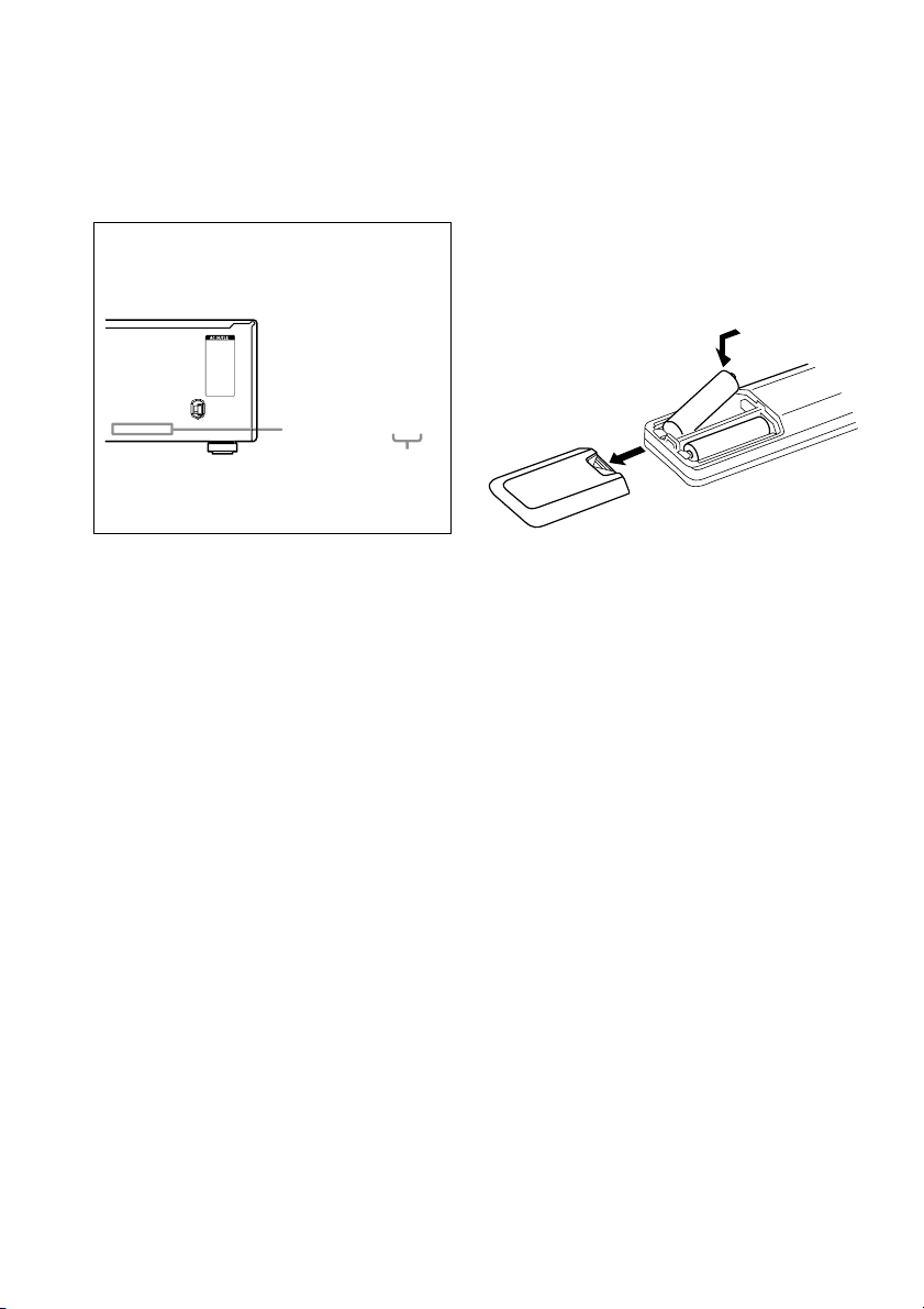
About area codes
The area code of the receiver you purchased is
shown on the lower portion of the rear panel (see
the illustration below).
-
-
-
Any differences in operation, according to the
area code, are clearly indicated in the text, for
example, “Models of area code AA only”.
Area code
Note for the supplied remote
The DVD button on the remote is not available.
Inserting batteries into the
remote
Insert R6 (size-AA) batteries with the + and –
properly oriented in the battery compartment.
When using the remote, point it at the remote
sensor g on the receiver.
]
}
}
]
Tip
The instructions in this manual describe the controls
on the receiver. You can also use the controls on the
supplied remote if they have the same or similar
names as those on the receiver. For details on the use
of your remote, see pages 24–27.
Tip
Under normal conditions, the batteries should last for
about 6 months. When the remote no longer operates
the receiver, replace all batteries with new ones.
Notes
• Do not leave the remote in an extremely hot or
humid place.
• Do not use a new battery with an old one.
• Do not expose the remote sensor to direct sunlight
or lighting apparatuses. Doing so may cause a
malfunction.
• If you don’t use the remote for an extended period
of time, remove the batteries to avoid possible
damage from battery leakage and corrosion.
GB
4
Page 5
List of Button Locations and Reference Pages
How to use this page
Use this page to find the location of buttons that are
mentioned in the text.
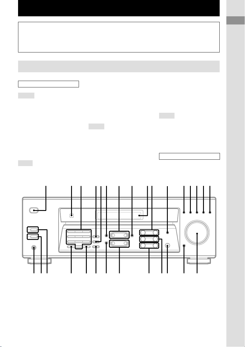
Main unit
ALPHABETICAL ORDER
A – H
AM 8 (13, 14)
BALANCE L/R q; (12)
BASS +/– wa (12)
BASS BOOST ql (12)
CD qg (8, 12)
DIRECT wg (13)
DISPLAY qa (12, 16)
Display 9 (11-16, 18, 19)
FM 6 (13, 14)
FM MODE wd (14)
I – O
IR (receptor) 2 (4, 22)
1 2 3 456 7 8 9q; qa qsqd qf qgqh
MASTER VOLUME qj (12, 20)
MD/TAPE qf (8, 12)
MEMORY/ENTER wf (13, 15,
18)
MUTING qk (12, 20)
NAME 5 (18)
Numeric buttons 3 (13)
P – S
PHONES wl (12, 21)
PRESET/PTY SELECT +/–
(models of area code CEL,
CEK) 7 (15, 16)
PRESET TUNING +/– (models of
area code U) 7 (15, 23)
PTY (models of area code CEL,
CEK) 4 (16)
Illustration number
r
NAME 5 (18)
Name of button/part Reference page
RR
SHIFT wh (15)
SLEEP (models of area code U)
4 (19)
SPEAKERS A wj (10, 12)
SPEAKERS B wk (10, 12)
T – Z
TREBLE +/– w; (12)
TUNER qh (8, 12-15, 18)
TUNING/CHAR +/– ws (14, 18)
VIDEO 1 qs (12)
VIDEO 2 qd (8, 12)
BUTTON DESCRIPTIONS
?/1 (power) 1 (11, 13, 23)
List of Button Locations and Reference Pages
wl
g
qjqkqlw;wawswdwfwgwhwjwk
GB
5
Page 6

Hooking Up the Components
Required cords
A Audio cord (not supplied)
White (L) White (L)
Red (R) Red (R)
B Speaker cords (not supplied)
(+) (+)
(–)(–)
Before you get started
• Turn off the power to all components before making any connections.
• Do not connect the AC power cord until all of the connections are completed.
• Be sure to make connections firmly to avoid hum and noise.
• When connecting an audio cord, be sure to match the color-coded pins to the appropriate jacks on the
components: white (left, audio) to white; and red (right, audio) to red.
GB
6
Page 7
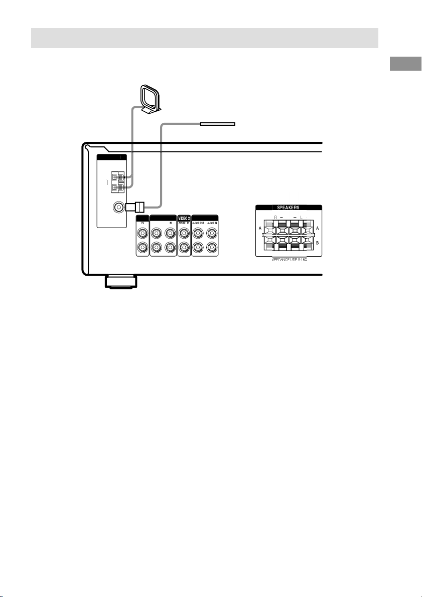
Antenna hookups
OU
M
E
1
AM loop antenna
(supplied)
FM wire antenna*
(supplied)
AXIAL
D
D/TAP
T
VIDEO
* The shape of the connector varies depending on the area code.
Notes on antenna hookups
• To prevent noise pickup, keep the AM loop
antenna away from the receiver and other
components.
• If you have poor AM reception, connect a
6 to 15 meters (20 to 50 feet) insulated wire
(not supplied) to the AM antenna terminal in
addition to the AM loop antenna. Try to extend
the wire outdoors and keep it horizontal.
• Be sure to fully extend the FM wire antenna.
• After connecting the FM wire antenna, keep it
as horizontal as possible.
Hooking Up the Components
I
GB
7
Page 8
ç
N
OUT
6
E
VIDEO 1
S
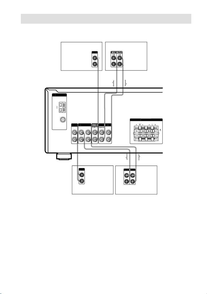
Audio/Video component hookups
Video Component Hookups
VCR
VCR
AXIAL
D
D/TAP
CD player
Audio Component Hookups
Note on video component
hookups
Use the function buttons (VIDEO 2,
MD/TAPE, CD, TUNER) to select the
VIDEO 1 AUDIO OUT signal. You can record
this audio signal by connecting a recording
component such as a cassette deck (to the
VIDEO 1 AUDIO OUT jack).
PEAKER
AUDIO I
IMPEDANCE USE 8-1
MD or Tape deck
GB
8
Page 9
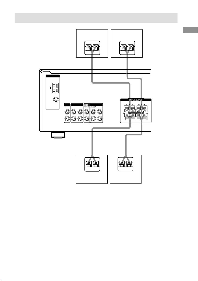
Speaker system hookups
E
e
E
e
e
E
e
N
OU
E
1
AXIAL
Speaker A (L)Speaker A (R)
D
D/TAP
T
VIDEO
AUDIO I
-1
Hooking Up the Components
Speaker B*
(R)
* If you have an additional front speaker system, connect them to the SPEAKERS B terminals.
Tips
• Twist the stripped ends of the cords about 15 mm
(2/3 inch). Be sure to match the speaker cord to the
appropriate terminal on the components: + to + and
– to –. If the cords are reversed, the sound will be
distorted and will lack bass.
• To avoid damaging your speakers, make sure that
you turn down the volume before you turn off the
receiver. When you turn on the receiver, the volume
remains at the level you turn off the receiver.
Speaker B*
(L)
GB
9
Page 10

To avoid short-circuiting the
speakers
Short-circuiting of the speakers may damage
the receiver. To prevent this, make sure to take
the following precautions when connecting the
speakers.
Make sure the stripped ends of each
speaker cord does not touch another
speaker terminal, the stripped end of
another speaker cord or the metal parts
of the receiver.
Examples of poor conditions of the
speaker cord
Stripped speaker cord is touching another
speaker terminal.
Selecting the speaker system
To drive the speakers, select the speaker system
as follows. The SPEAKERS indicator(s)
light(s) up.
To drive Press SPEAKERS button
Speaker System A
(connected to the
SPEAKERS A
terminals)
Speaker System B
(connected to the
SPEAKERS B
terminals)
Both speaker
systems A and B
(parallel connection)
Tips
• Press SPEAKERS A or B button again to deselect
the speakers.
• The default speaker system is Speaker System A.
A
B
A and B
Stripped cords are touching each other
due to excessive removal of insulation.
GB
10
Page 11

T
Other hookups
AC OUTLET*
Caution
Make sure that the total power consumption of the
component connected to the receiver’s AC OUTLET
does not exceed the wattage stated on the rear panel.
Do not connect high-wattage electrical home
appliances such as electric irons, fans, or TVs to this
outlet.
Hooking Up the Components
AC OUTLE
AC power cord
To a wall outlet
* The configuration and shape of AC outlets vary
according to the model and country to which the
receiver is shipped.
Connecting the AC power
cord
Connect the AC power cord(s) of your audio/
video components to a wall outlet.
If you connect other audio/video components to
the AC OUTLET on the receiver, the receiver
will supply power to the connected component,
allowing you to turn the whole system on or off
when you turn the receiver on or off.
Note
If the AC power cord is disconnected for about one
week, the receiver’s entire memory will be cleared.
Clearing the receiver’s
memory
Before using your receiver for the first time, or
when you want to clear the receiver’s memory,
do the following.
1 Turn off the receiver.
2 Hold down ?/1 for 5 seconds.
“INITIAL” appears in the display and all of
the following items are reset or cleared:
• All preset stations are reset or cleared.
• All index names (of preset stations and
program sources) are cleared.
• The master volume is set to VOL MIN.
• All adjustments made (BALANCE,
speaker system, etc.) are reset to factory
settings.
GB
11
Page 12

Basic Operations
Selecting the component
Press a function button to select the component
you want to use.
To select Press
VCR VIDEO 1 or VIDEO 2
MD or Tape deck MD/TAPE
CD player CD
Built in tuner TUNER
To Do this
Mute the sound
Listen with
headphones
Press MUTING. Press again
to restore the sound. The
muting function is canceled
when you turn the power on
or turn the MASTER
VOLUME clockwise to turn
the volume up.
Connect the headphones to
the PHONES jack and set the
SPEAKERS A and B buttons
to OFF.
After turning on the component you selected,
select the component and play the program
source.
• After selecting VCR, turn on the TV and set the
TV’s video input to match the component you
selected.
Adjusting the sound
The default settings are underlined.
To Do this
Adjust the volume
VOL MIN
Adjust the balance
BALANCE
Adjust the tone
quality
BASS 0 dB
TREB 0 dB
Reinforce the bass
Off
Turn MASTER VOLUME.
Every time you turn the
MASTER VOLUME, the
display changes as follows:
VOL MIN y VOL 1 y
… yVOL MAX
Press BALANCE L/R. Every
time you press BALANCE
L/R, the display changes as
follows:
BAL L+8… y BAL L+1
y BALANCE y BAL
R+1… y BAL R+8
Press BASS +/– and
TREBLE +/–. You can select
a tone level of –10 dB to
+10 dB in 2 dB steps.
Press BASS BOOST. The
BASS BOOST indicator
lights up.
Changing the display
DISPLAY
Each time you press DISPLAY, the display
changes cyclically as follows:
Index name of the component* t Selected
component
When the tuner is selected
Index name of the preset station* or program
station name** t Frequency t Program type
indication** t Radio text** t Current
time**
* Index name appears only when you have assigned
one to the component or preset station (page 18).
Index name does not appear when only blank
spaces have been entered, or it is the same as the
function.
** During RDS reception only. (Models of area code
CEL, CEK only. See page 16).
12
GB
Page 13

Receiving Broadcasts
Before receiving broadcasts, make sure you
have connected FM and AM antennas to the
receiver (page 7).
Storing FM stations
automatically
(AUTOBETICAL)
Notes
• Do not press any button on the receiver or supplied
remote during autobetical operation.
• If you move to another area, repeat this procedure
to store stations in your new area.
• For details on tuning the stored stations, see page
15.
• If you move the antenna after storing stations with
this procedure, the stored settings may no longer be
valid. If this happens, repeat this procedure to store
the stations again.
Basic Operation/Receiving Broadcasts
(Models of area code CEL, CEK only)
This function lets you store up to 30 FM and
FM RDS stations in alphabetical order without
redundancy. Additionally, it only stores the
stations with the clearest signals.
If you want to store FM or AM stations one by
one, see “Presetting radio stations” on page 15.
1 Press ?/1 to turn off the receiver.
2 Hold down MEMORY/ENTER and press
?/1 to turn the receiver back on.
“AUTO-BETICAL SELECT” appears in
the display and the receiver scans and stores
all the FM and FM RDS stations in the
broadcast area.
For RDS stations, the tuner first checks for
stations broadcasting the same program,
then stores only the one with the clearest
signal. The selected RDS stations are sorted
alphabetically by their Program Service
name, then assigned a 2-character preset
code. For more details on RDS, see page 16.
Regular FM stations are assigned
2-character preset codes and stored after the
RDS station.
When done, “FINISH” appears in the
display momentarily and the receiver
returns to the normal operation.
Direct tuning
You can enter a frequency of the station you
want directly by using the numeric buttons on
the receiver or the supplied remote.
1 Press TUNER.
The last received station is tuned in.
2 Press FM or AM to select the FM or AM
band.
3 Press DIRECT.
4 Press the numeric buttons to enter the
frequency.
Example 1: FM 102.50 MHz
1
0
2
b
5 0
b
5 0
b
b
b
b
Example 2: AM 1350 kHz
(You don’t have to enter the last “0” when the
tuning scale is set to 10 kHz.)
1
3
b
If you cannot tune in a station and the
entered numbers flash
Make sure you’ve entered the right
frequency. If not, repeat steps 3 and 4.
If the entered numbers still flash, the
frequency is not used in your area.
continued
13
GB
Page 14

Direct Tuning (continued)
Automatic tuning
5 If you’ve tuned in an AM station, adjust
the direction of the AM loop antenna for
optimum reception.
6 Repeat steps 2 to 5 to receive another
station.
Tips
• If you do not remember the precise frequency, press
TUNING/CHAR + or TUNING/CHAR – after
entering the value close to the frequency you want.
The receiver automatically tunes in the station you
want. If the frequency seems to be higher than the
entered value, press TUNING/CHAR +, and if the
frequency seems to be lower than the entered value,
press TUNING/CHAR –.
• If “STEREO” flashes in the display and the FM
stereo reception is poor, press FM MODE to change
to monaural (MONO). You will not be able to enjoy
the stereo effect, but the sound will be less
distorted. To return to stereo mode, press FM
MODE again.
The tuning scale differs depending on the area code
as shown in the following table. For details on area
codes, see page 4.
Area code FM AM
U 100 kHz 10 kHz*
CEL, CEK 50 kHz 9 kHz
* The AM tuning scale can be changed (page 23).
If you don’t know the frequency of the station
you want, you can let the receiver scan all
available stations in your area.
1 Press TUNER.
The last received station is tuned in.
2 Press FM or AM to select the FM or AM
band.
3 Press TUNING/CHAR + or
TUNING/CHAR –.
Press TUNING/CHAR + to scan from low
to high; press TUNING/CHAR – to scan
from high to low.
The receiver stops scanning whenever a
station is received.
When the receiver reaches either end of
the band
Scanning is repeated in the same direction.
4 To continue scanning, press
TUNING/CHAR + or TUNING/CHAR –
again.
Preset tuning
After you have tuned in stations using Direct
Tuning or Automatic Tuning, you can preset
them to the receiver. Then you can tune in any
of the stations directly by entering its
2-character preset code on the receiver or the
supplied remote. Up to 30 FM or AM stations
can be preset. The receiver will also scan all the
stations that you have preset.
Before tuning to preset stations, be sure to
preset them by performing steps on “Presetting
radio stations” (page 15).
14
GB
Page 15

Presetting radio stations
1 Press TUNER.
The last received station is tuned in.
2 Tune in the station that you want to
preset using Direct Tuning (page 13) or
Automatic Tuning (page 14).
3 Press MEMORY/ENTER.
“MEMORY” appears in the display for a
few seconds.
Do steps 4 to 6 before “MEMORY” goes
out.
4 Press SHIFT to select a memory page
(A, B or C).
Each time you press SHIFT, the letter “A”,
“B”, or “C” appears in the display.
5 Press the numeric buttons to select a
preset number.
If “MEMORY” goes out before you press
the preset number, start again from step 3.
6 Repeat steps 2 to 5 to preset another
station.
To change a preset number to
another station
Do steps 1 to 5 to preset a new station to the
number.
Note
If the AC power cord is disconnected for about one
week, the preset stations will be cleared from the
receiver’s memory, and you will have to preset the
stations again.
Tuning to preset stations
You can tune the preset stations by either of the
following two ways.
Scanning the preset stations
1 Press TUNER.
The last received station is tuned in.
2 Press PRESET TUNING +* or PRESET
TUNING –* repeatedly to select the
preset station you want.
Each time you press the button, the receiver
tunes in one preset station at a time, in the
corresponding order and direction as
follows:
nA1˜A2˜...˜A0˜B1˜B2˜...˜B0N
nC0˜...C2˜C1N
* For models of area code CEL, CEK: PRESET/PTY
SELECT + or PRESET/PTY SELECT – .
Using the preset codes
You can tune directly to a preset station by
entering its preset number on the receiver or the
supplied remote.
1 Press TUNER.
The last received station is tuned in.
2 Press SHIFT to select a memory page
(A, B, or C), then press the preset
number of the station you want using
the numeric buttons.
Receiving Broadcasts
15
GB
Page 16

Using the Radio Data
System (RDS)
(Models of area code CEL, CEK only)
This receiver also allows you to use RDS
(Radio Data System), which enables radio
stations to send additional information along
with the regular program signal. You can use
the following convenient RDS features:
– Displaying RDS information
– Scanning preset stations by program type
Note that RDS is operable only for FM
stations.*
* Not all FM stations provide RDS service, nor do
they provide the same types of services. If you are
not familiar with the RDS services in your area,
check with your local radio stations for details.
Receiving RDS broadcasts
Simply select a station on the FM band
using direct tuning (page 13), automatic
tuning (page 14), or preset tuning (page
14).
When you tune in a station that provides RDS
services, the program station name normally
appears in the display.
Note
RDS may not work properly if the station you tuned
to is not transmitting the RDS signal properly or if the
signal strength is weak.
Displaying RDS information
Notes
• If there is an emergency announcement by
government authorities, “ALARM” flashes in the
display.
• When the message consists of 9 characters or more,
the message scrolls across the display.
• If a station does not provide a particular RDS
service, “NO XXX” (such as “NO PTY”) appears in
the display.
Scanning preset stations by
program type
You can tune in preset stations according to a
program type that you specify. The receiver
scans for stations in its preset memory
currently broadcasting the specified program
type.
1 Press PTY.
2 Press PRESET/PTY SELECT + or
PRESET/PTY SELECT – to select the
program type.
See the table below for the information on
each program type.
3 Press PTY.
When the receiver is scanning stations,
“SEARCH” and the program type are
displayed alternately.
When the receiver finds a station, the
receiver stops scanning. When the receiver
could not find any preset stations currently
broadcasting the specified program type,
“NO PTY” appears in the display.
While receiving an RDS station, press
DISPLAY.
Each time you press the button, RDS
information on the display changes cyclically
as follows:
Program Station name t Frequency t
Program Type indication
Radio Text indicationb) t Current Time
indication (in 24-hour system)
a) Type of program being broadcast (page 17).
b) Text messages sent by the RDS station.
GB
16
a)
t
Page 17

Description of program types
Program type Description
indication
NEWS
AFFAIRS
INFO
SPORT
EDUCATE
DRAMA
CULTURE
SCIENCE
VARIED
POP M
ROCK M
EASY M
LIGHT M
CLASSICS
OTHER M
WEATHER
FINANCE
CHILDREN
SOCIAL
RELIGION
PHONE IN
TRAVEL
News programs
Topical programs that expand on
current news
Programs offering information on a
wide spectrum of subjects,
including consumer affairs and
medical advice
Sports programs
Educational programs, such as
“how-to” and advice programs
Radio plays and serials
Programs about national or
regional culture, such as language
and social concerns
Programs about the natural
sciences and technology
Other types of programs such as
celebrity interviews, panel games,
and comedy
Popular music programs
Rock music programs
Easy Listening
Instrumental, vocal, and choral
music
Performances of major orchestras,
chamber music, opera, etc.
Music that does not fit into any
categories above, such as Rhythm
& Blues and Reggae
Weather information
Stock market reports and trading,
etc.
Programs for children
Programs about people and the
things that affect them
Programs of religious content
Programs where members of the
public express their views by
phone or in a public forum
Programs about travel. Not for
announcements that are located by
TP/TA.
Program type Description
indication
LEISURE
JAZZ
COUNTRY
NATION M
OLDIES
FOLK M
DOCUMENT
NONE
Programs on recreational activities
such as gardening, fishing,
cooking, etc.
Jazz programs
Country music programs
Programs featuring the popular
music of the country or region
Programs featuring oldies music
Folk music programs
Investigative features
Any programs not defined above
Receiving Broadcasts
17
GB
Page 18

Other Operations
Naming preset stations
and program sources
You can enter a name (index name) of up to 8
characters for preset stations and program
sources. These names (for example, “VHS”)
appear in the receiver’s display when a station
or program source is selected. Note that no
more than one name can be entered for each
preset station or program source.
This function is useful for distinguishing
components of the same kind. For example,
two VCRs can be specified as “VHS” and
“8MM”, respectively. It is also handy for
identifying components connected to jacks
meant for another type of component, for
example, a second CD player connected to the
MD/TAPE jacks.
1 To name a preset station
Press TUNER, then tune in the preset
station you want to create an index
name for.
The last station you received is tuned in.
If you are not familiar with how to tune in
preset stations, see “Tuning to preset
stations” on page 15.
To name a program source
Select the program source (component)
to be named.
2 Press NAME.
3 Create an index name by using the
TUNING/CHAR and NAME:
Press TUNING/CHAR + or TUNING/
CHAR – to select a character, then press
NAME to move the cursor to the next
position.
To insert a space
Press TUNING/CHAR + or TUNING/
CHAR – until a blank space appears in the
display.
If you’ve made a mistake
Press NAME repeatedly until the character
to be changed flashes, then press TUNING/
CHAR + or TUNING/CHAR – to select the
right character.
4 Press MEMORY/ENTER.
5 Repeat steps 2 to 4 to assign index
name for another station or program
source.
Note
(Models of area code CEL, CEK only)
You cannot change the name of an RDS station.
Recording
Before you begin, make sure you’ve connected
all components properly.
Recording on an audio tape
or MiniDisc
You can record on a cassette tape or MiniDisc
using the receiver. See the operating
instructions of your cassette deck or MD deck
if you need help.
1 Select the component to be recorded.
2 Prepare the component for playing.
For example, insert a CD into the CD
player.
3 Insert a blank tape or MD into the
recording deck and adjust the
recording level, if necessary.
4 Start recording on the recording deck,
then start playback on the playback
component.
18
GB
Page 19

Recording on a video tape
You can record from a VCR, a TV, or an LD
player using the receiver. You can also add
audio from a variety of audio sources when
editing a video tape. See the operating
instructions of your VCR or LD player if you
need help.
1 Select the program source to be
recorded.
2 Prepare the component for playing.
For example, insert the laser disc you want
to record into the LD player.
3 Insert a blank video tape into the VCR
(VIDEO 1) for recording.
4 Start recording on the recording VCR,
then start playing the video tape or
laser disc you want to record.
Tip
You can record the sound from any audio source onto
a video tape while copying from a video tape or laser
disc. Locate the point where you want to start
recording from another audio source, select the
program source, then start playback. The audio from
that source will be recorded onto the audio track of
the video tape instead of the audio from the original
medium. To resume audio recording from the original
medium, select the video source again.
Using the Sleep Timer
You can set the receiver to turn off
automatically at a specified time.
Press SLEEP on the front panel (except
for models of area code CEL, CEK) or on
the remote while the power is on.
Each time you press the button, the display
changes cyclically as follows:
2 – 00 – 00 t 1 – 30 – 00 t 1 – 00 – 00 t
0 – 30 – 00 t OFF
The display dims after you have specified the
time.
Tip
To check the remaining time before the receiver turns
off, press SLEEP. The remaining time appears in the
display.
Other Operations
19
GB
Page 20

Additional Information
Precautions
On safety
Should any solid object or liquid fall into the cabinet,
unplug the receiver and have it checked by qualified
personnel before operating it any further.
On power sources
• Before operating the unit, check that the operating
voltage is identical with your local power supply.
The operating voltage is indicated on the nameplate
at the rear of the receiver.
• The unit is not disconnected from the AC power
source (mains) as long as it is connected to the wall
outlet, even if the receiver itself has been turned off.
• If you are not going to use the receiver for a long
time, be sure to disconnect the receiver from the
wall outlet. To disconnect the AC power cord,
grasp the plug itself; never pull the cord.
• (Models of area code U only)
One blade of the plug is wider than the other for the
purpose of safety and will fit into the wall outlet
only one way. If you are unable to insert the plug
fully into the outlet, contact your dealer.
• AC power cord must be changed only at the
qualified service shop.
On heat buildup
Although the unit heats up during operation, this is
not a malfunction. If you continuously use this unit at
a large volume, the cabinet temperature of the top,
side and bottom rises considerably. To avoid burning
yourself, do not touch the cabinet.
On placement
• Place the receiver in a location with adequate
ventilation to prevent heat buildup and prolong the
life of the receiver.
• Do not place the receiver near heat sources, or in a
place subject to direct sunlight, excessive dust or
mechanical shock.
• Do not place anything on top of the cabinet that
might block the ventilation holes and cause
malfunctions.
On operation
Before connecting other components, be sure to turn
off and unplug the receiver.
On cleaning
Clean the cabinet, panel and controls with a soft cloth
slightly moistened with a mild detergent solution. Do
not use any type of abrasive pad, scouring powder or
solvent such as alcohol or benzine.
If you have any question or problem concerning your
receiver, please consult your nearest Sony dealer.
Troubleshooting
If you experience any of the following
difficulties while using the receiver, use this
troubleshooting guide to help you remedy the
problem. Should any problem persist, consult
your nearest Sony dealer.
There is no sound or only a very low-level sound
no matter which component is selected.
• Check that the speakers and components are
connected securely and correctly.
• Check that both the receiver and all the
components are turned on.
• Check that the MASTER VOLUME control is
not set at VOL MIN.
• Press MUTING to cancel the muting function.
• Check that the headphones are not connected.
• The protective device on the receiver has been
activated because of a short circuit (“PROTECT”
flashes). Turn off the receiver, eliminate the
short-circuit problem and turn on the power
again.
There is no sound from a specific component.
• Check that the component is connected correctly
to the audio input jacks for that component.
• Check that the cord(s) used for the connection is
(are) fully inserted into the jacks on both the
receiver and the component.
• Check that you have selected the correct
component on the receiver.
20
GB
Page 21

There is no sound from one of the front
75
speakers.
Connect a pair of headphones to the PHONES jack
to verify that sound is output from the headphones
(page 12).
If only one channel is output from the headphones,
the component may not be connected to the
receiver correctly. Check that all the cords are fully
inserted into the jacks on both the receiver and the
component.
If both channels are output from the headphones,
the front speaker may not be connected to the
receiver correctly. Check the connection of the
front speaker which is not outputting any sound.
The left and right sounds are unbalanced or
reversed.
• Check that the speakers and components are
connected correctly and securely.
• Adjust the balance (page 12).
There is severe hum or noise.
• Check that the speakers and components are
connected securely.
• Check that the connecting cords are away from a
transformer or motor, and at least 3 meters away
from a TV set or fluorescent light.
• Move your TV away from the audio components.
• The plugs and jacks are dirty. Wipe them with a
cloth slightly moistened with alcohol.
Recording cannot be done.
Check that the components are connected
correctly.
The FM reception is poor.
Use a 75-ohm coaxial cable (not supplied) to
connect the receiver to an outdoor FM antenna as
shown below. If you connect the receiver to an
outdoor antenna, ground it against lightning. To
prevent a gas explosion, do not connect the ground
wire to a gas pipe.
Radio stations cannot be tuned in.
• Check that the antennas are connected securely.
Adjust the antennas and connect an external
antenna if necessary.
• The signal strength of the stations is too weak
(when tuning in with automatic tuning). Use
direct tuning.
• Make sure you set the tuning interval correctly
(when tuning in AM stations with direct tuning).
• No stations have been preset or the preset
stations have been cleared (when tuning by
scanning preset stations). Preset the stations
(page 15).
RDS does not work.*
• Make sure that you’re tuned to an FM RDS
station.
• Select a stronger FM station.
The RDS information that you want does not
appear.*
Contact the radio station and find out whether they
actually provide the service in question. If so, the
service may be temporarily out of order.
* Models of area code CEL, CEK only.
continued
Additional Information
Receiver
Ground wire
(not supplied)
To ground
AXIAL
Outdoor FM antenna
21
GB
Page 22

Troubleshooting (continued)
Specifications
The remote does not function.
• Point the remote at the remote sensor g on the
receiver.
• Remove any obstacles in the path between the
remote and the receiver.
• Replace both batteries in the remote with new
ones, if they are weak.
• Make sure you select the correct function on the
remote.
• If the remote is set to operate the TV only, use
the remote to select a source or component other
than TV before operating the receiver or other
component.
Clearing the receiver’s memory
To clear See
All memorized settings page 11
AUDIO POWER SPECIFICATIONS
POWER OUTPUT AND TOTAL
HARMONIC DISTORTION:
With 8 ohm loads, both channels driven, from
40 – 20,000 Hz; rated 100 watts per channel
minimum RMS power, with no more than
0.09 % total harmonic distortion from 250
milliwatts to rated output (Models of area code
U only).
Amplifier section
POWER OUTPUT
Models of area code U
Rated Power Output at Stereo Mode
(8 ohms 40 Hz – 20 kHz, THD 0.09 %)
Models of area code CEL, CEK
Rated Power Output at Stereo Mode
(8 ohms 1 kHz, THD 0.7 %)
1) Measured under the following conditions:
Area code Power requirements
CEL, CEK 230 V AC, 50 Hz
Frequency response
CD, MD/TAPE,
VIDEO 1, VIDEO 2
100 W + 100 W
100 W + 100 W
20 Hz – 50 kHz
+0/–0.5 dB (with bass
boost bypassed)
1)
22
GB
Inputs (Analog)
CD, MD/TAPE,
VIDEO 1, VIDEO 2
2) INPUT SHORT.
3) Weighted network, input level.
Outputs
MD/TAPE, VIDEO 1
Bass Boost: +8 dB at 70 Hz
Tone: ±10 dB at 100 Hz and
Sensitivity: 250 mV
Impedance: 50 kilohms
S/N2): 85 dB
(A, 250 mV3))
Voltage: 250 mV
Impedance: 10 kilohms
10 kHz
Page 23

FM tuner section
Tuning range 87.5 - 108.0 MHz
Antenna terminals 75 ohms, unbalanced
Intermediate frequency
Sensitivity
Mono: 18.3 dBf, 2.2 µV/75 ohms
Stereo:
Usable sensitivity 11.2 dBf, 1 µV/75 ohms
S/N
Mono: 76 dB
Stereo: 70 dB
Harmonic distortion at 1 kHz
Mono: 0.5%
Stereo: 0.8%
Separation 35 dB at 1 kHz
Frequency response 30 Hz – 15 kHz,
Selectivity 60 dB at 400 kHz
10.7 MHz
38.3 dBf, 22.5 µV/75 ohms
+0.5/–2 dB
AM tuner section
Tuning range
Models of area code U
With 10-kHz tuning scale: 530 – 1710 kHz
With 9-kHz tuning scale: 531 – 1710 kHz
Models of area code CEL, CEK
With 9-kHz tuning scale: 531 – 1602 kHz
Antenna Loop antenna
Intermediate frequency
Usable sensitivity 50 dB/m (at 1,000 kHz or
S/N 45 dB (at 50 mV/m)
Harmonic distortion 1.0 % (50 mV/m,
Selectivity
At 9 kHz: 35 dB
At 10 kHz: 40 dB
450 kHz
999 kHz)
400 Hz)
4)
4)
4) You can change the AM tuning scale to 9 kHz or
10 kHz. After tuning in any AM station, turn off
the receiver. Hold down PRESET TUNING + and
press ?/1. All preset stations will be erased when
you change the tuning scale. To reset the scale to
10 kHz (or 9 kHz), repeat the procedure.
General
Power requirements
Area code Power requirements
U 120 V AC, 60 Hz
CEL, CEK 230 V AC, 50/60 Hz
Power consumption
Area code Power consumption
U 190 W
CEL, CEK 210 W
Power consumption (during standby mode)
0.5 W (for models of all area code)
AC outlets
Area code AC outlets
U 1 switched, 120 W/1A MAX
CEL, CEK 1 switched, 100 W MAX
Dimensions 430 × 145 × 300 mm
Mass (Approx.) 7.0 kg (15 lb 7 oz)
Supplied accessories
FM wire antenna (1)
AM loop antenna (1)
Remote commander RM-U185 (1)
R6 (size-AA) batteries (2)
For details on the area code of the component you
are using, see page 4.
Design and specifications are subject to change
without notice.
(167/8 × 56/8 × 116/8 in.)
including projecting parts
and controls
Additional Information
23
GB
Page 24

Remote button description
You can use the remote RM-U185 to operate
the components in your system.
SYSTEM
STANDBY
VIDEO 2
CD
F
ENTER
f
?/1
DVD
TUNER
ˆ
•
g
SLEEPAV?/1
VIDEO 1
MD/TAPE
TOP MENU DVD MENU
123
G
456
789
0
+
+
)
P
+
+
++
TV CH
––
D. TUNING
ENTER
RETURN
TV/VIDEO
ANT
TV/VTR
D.SKIP
p
BASS BOOST
MUTING
MASTER
VOL
SHIFT
>10
– /– –
–
CH/PRESET
=
0
(
L BALANCE R
–
TREBLE
–
BASS
TV VOL
The tables below show the settings of each
button.
Remote Operations Function
Button
SLEEP Receiver Activates the sleep
?/1 Receiver Turns the receiver on or
VIDEO 1 Receiver To watch VCR.
VIDEO 2 Receiver To watch VCR.
DVD Receiver To watch DVD.
MD/TAPE
Receiver To listen to Minidisc or
CD Receiver To listen to compact disc.
TUNER Receiver To listen to radio
SHIFT Receiver Press repeatedly to select
D.TUNING
BALANCE
Receiver Tuner station direct
Receiver Adjust the balance.
L/R
BASS Receiver Reinforce the bass.
BOOST
TREBLE Receiver Adjust the treble tone
+/– quality.
MUTING Receiver Mutes the sound from the
BASS +/– Receiver Adjust the bass tone
function and the duration
which the receiver turns
off automatically.
off.
(VTR mode 3)
(VTR mode 1)
audio tape.
programs.
a memory page for
presetting radio stations
or tuning to preset
stations.
key-in-mode.
receiver.
quality.
24
Note
When you press the function buttons (VIDEO 1,
VIDEO 2, DVD), the input mode of the TV might not
switch to the corresponding input mode that you
want. In this case, press the TV/VIDEO button to
switch the input mode of the TV.
GB
Page 25

Remote Operations Function
Button
MASTER Receiver Adjusts the master
VOL +/– volumn of the receiver.
AV ?/1 TV/VCR/ Turns the audio and
SYSTEM
STANDBY
(Press tuner/CD components.
AV ?/1 player/VCD
and ?/1 player/LD
at the same player/DVD
time) player/MD
0-9 Receiver Use with “SHIFT” button
>10 CD player/ Selects track numbers
CD player/ video components on or
VCD player/ off.
LD player/
DVD player/
MD deck/
DAT deck
Receiver/TV/ Turns off the receiver and
VCR/Satellite other Sony audio/video
deck/DAT
deck/Tape
deck
to select tuner preset
station numeric input
during DIRECT
TUNING or MEMORY
mode.
CD player/ Selects track numbers.
VCD player/ 0 selects track 10.
LD player/
MD deck/
DAT deck
TV/VCR/ Selects channel numbers.
Satellite tuner
VCD player/ over 10.
LD player/
MD deck/
Tape deck
Remote Operations Function
Button
ENTER TV/VCR/ After selecting a channel,
RETURN VCD player Go back to previous
CH/
PRESET +/–
./> VCR/CD Skips tracks.
m/M CD player/ Searches tracks
N VCR/CD Starts play.
Satellite tuner/ disc or track using the
LD player/ numeric buttons, press
MD deck/ to enter the value.
DAT deck/
Tape deck
menu.
Receiver Scans and selects preset
stations.
TV/VCR/ Selects preset channels.
Satellite tuner
player/
VCD player/
LD player/
DVD player/
MD deck/
DAT deck/
Tape deck
VCD player/ (forward or backward).
DVD player
VCR/LD Fastforwards or
player/ rewinds.
MD deck/
DAT deck/
Tape deck
player/
VCD player/
LD player/
DVD player/
MD deck/
DAT deck/
Tape deck
Additional Information
continued
25
GB
Page 26

Remote button description
(continued)
Remote Operations Function
Button
X VCR/CD Pauses play or record.
player/ (Also starts recording
VCD player/ with components in
LD player/ record standby.
DVD player/
MD deck/
DAT deck/
Tape deck
x VCR/CD Stops play.
player/
VCD player/
LD player/
DVD player/
MD deck/
DAT deck/
Tape deck
ANT VCR Selects output signal
TV/VTR from the aerial
terminal: TV signal or
VCR program.
D.SKIP CD player/ Skips discs (multi-disc
VCD player/ changer only).
DVD player/
MD deck
TOP DVD player Displays DVD title.
MENU
DVD DVD player Displays DVD menu.
MENU
ENTER DVD player Enters the selection.
ˆ DVD player Return to the previous
menu or exits the menu.
F/f/G/g DVD player Selects a menu item.
Remote Operations Function
Button
-/-- TV Selects the channel
entry mode, either one
or two digit.
TV/ TV Selects input signal: TV
VIDEO input or video input.
TV TV Adjust the volume of
VOL +/– the TV.
TV TV Selects preset TV
CH +/– channels.
Notes
• Some functions explained in this section may not
work depending on the model of the receiver.
• The above explanation is intended to serve as an
example only.
Therefore, depending on the component the above
operation may not be possible or may operate
differently than described.
• The DVD function is not available for set operation.
26
GB
Page 27

Changing the factory
setting of a function button
If the factory settings of the FUNCTION
buttons do not match your system components,
you can change them. For example, if you have
a tape deck and you do not have an MD deck,
you can assign the MD/TAPE button to your
tape deck.
Note that the settings of the TUNER button
cannot be changed.
1 Hold down the Function button whose
function you want to change (for
example, MD/TAPE).
2 Press the corresponding button of the
component you want to assign to the
Function button (for example, 4 – Tape
deck).
The following buttons are assigned to select
the functions:
To operate Press
CD player 1
DAT deck 2
MD deck 3
Tape deck A 4
Tape deck B 5
LD player 6
VCR (command mode VTR 1*) 7
VCR (command mode VTR 2*) 8
VCR (command mode VTR 3*) 9
TV 0
DSS (Digital Satellite Receiver) >10
DVD ENTER
VCD player .
To reset a button to its factory
setting
Repeat the above procedure.
To reset all the function buttons to
their factory setting
Press ?/1, AV ?/1 and MASTER VOL – at
the same time.
Additional Information
* Sony VCRs are operated with a VTR 1, 2 or 3
setting. These correspond to Beta, 8MM and
VHS respectively.
Now you can use the MD/TAPE button to
control the tape deck.
27
GB
Page 28

Sony Corporation Printed in Indonesia
http://www.sony.net/
 Loading...