

Page 1

FM Ster eo
FM-AM Receiver
3-864-483-71(1)
Operating Instructions
Mode d’emploi
Gebruiksaanwijzing
Bruksanvisning
GB
F
NL
S
STR-DB925
1998 by Sony Corporation
Page 2

WARNING
Precautions
To prevent fire or shock
hazard, do not expose the
unit to rain or moisture.
To avoid electrical shock,
do not open the cabinet.
Refer servicing to qualified
personnel only.
Do not install the
appliance in a confined
space, such as a bookcase
or built-in cabinet.
On safety
Should any solid object or liquid fall into
the cabinet, unplug the receiver and have it
checked by qualified personnel before
operating it any further.
On power sources
• Before operating the receiver, check that
the operating voltage is identical with
your local power supply. The operating
voltage is indicated on the nameplate at
the rear of the receiver.
• The unit is not disconnected from the AC
power source (mains) as long as it is
connected to the wall outlet, even if the
unit itself has been turned off.
• If you are not going to use the receiver
for a long time, be sure to disconnect the
receiver from the wall outlet. To
disconnect the AC power cord, grasp the
plug itself; never pull the cord.
• AC power cord must be changed only at
the qualified service shop.
On placement
• Place the receiver in a location with
adequate ventilation to prevent heat
buildup and prolong the life of the
receiver.
• Do not place the receiver near heat
sources, or in a place subject to direct
sunlight, excessive dust or mechanical
shock.
• Do not place anything on top of the
cabinet that might block the ventilation
holes and cause malfunctions.
On operation
Before connecting other components, be
sure to turn off and unplug the receiver.
On cleaning
Clean the cabinet, panel and controls with
a soft cloth slightly moistened with a mild
detergent solution. Do not use any type of
abrasive pad, scouring powder or solvent
such as alcohol or benzine.
If you have any question or problem
concerning your receiver, please
consult your nearest Sony dealer.
GB
2
Page 3

About This Manual
The instructions in this manual are for model STR-DB925.
Check your model number by looking at the upper right
corner of the front panel.
Conventions
• The instructions in this manual describe the controls on
the receiver. You can also use the controls on the
supplied remote if they have the same or similar names
as those on the receiver. For details on the use of your
remote, refer to the separate operating instructions
supplied with the remote.
• The following icon is used in this manual:
z Indicates hints and tips for making the task easier.
TABLE OF CONTENTS
Hooking Up the Components 4
Unpacking 4
Antenna Hookups 5
Audio Component Hookups 6
Video Component Hookups 7
Digital Component Hookups 8
5.1 Input Hookups 10
Other Hookups 11
Hooking Up and Setting Up the
This receiver incorporates the Dolby
system and the DTS** Digital Surround System.
Manufactured under license from Dolby Laboratories Licensing
*
Corporation. DOLBY, the double-D symbol a, “PRO LOGIC,”
and Dolby Digital (AC-3) are trademarks of Dolby Laboratories
Licensing Corporation.
Manufactured under license from Digital Theater Systems, Inc. US
**
Pat. No. 5,451,942 and other worldwide patents issues and pending.
“DTS” and “DTS Digital Surround” are trademarks of Digital
Theater Systems, Inc. © 1996 Digital Theater Systems, Inc. All
rights reserved.
Demonstration Mode
The demonstration will activate the first time you turn on
the power. When the demonstration starts, the following
message appears in the display twice:
“Now Demonstration Mode!! If you finish
demonstration, please press POWER KEY while
this message appears in the display. Thank you!!”
To cancel the demonstration
Press 1/u to turn the receiver off during the previous
message. The next time you turn the receiver on, the
demonstration will not appear.
To view the demonstration
Hold down SET UP and press 1/u to turn on the power.
Note
Running the demonstration will clear the receiver’s
memory. For details on what will be cleared, see “Clearing
the receiver's memory” on page 19.
* Pro Logic Surround
Speaker System 12
Speaker System Hookup 13
Multi-Channel Surround Setup 14
Before You Use Your Receiver 19
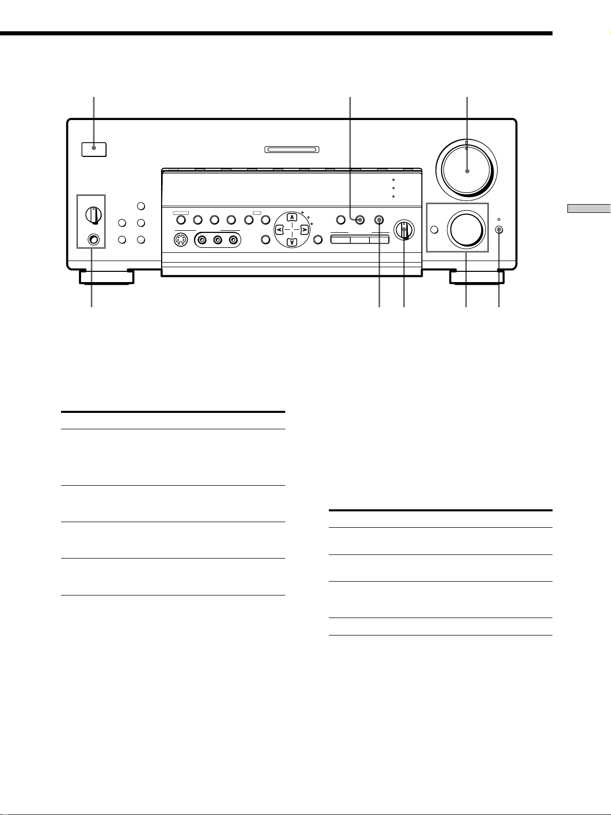
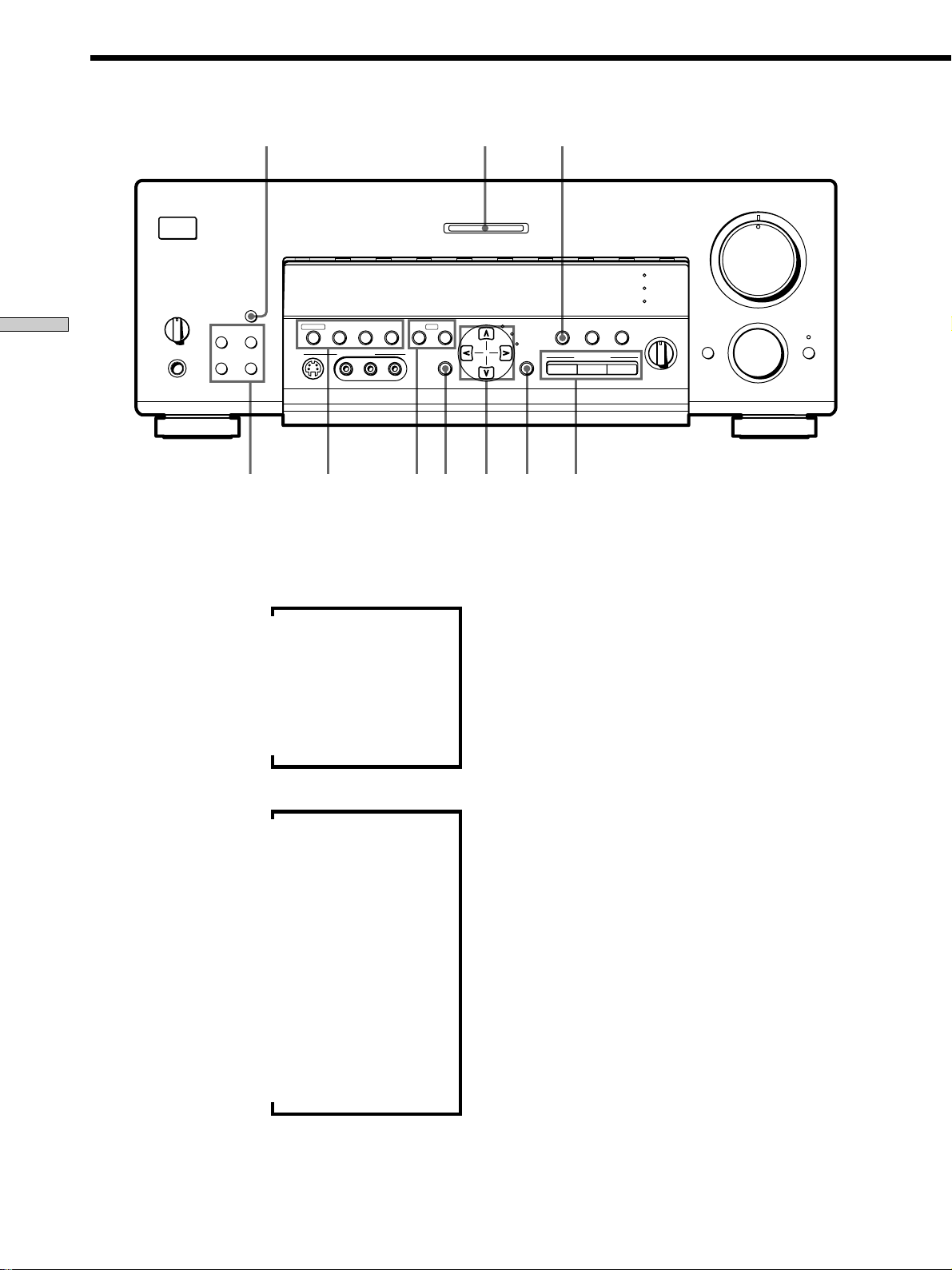
Location of Parts and Basic
Operations 22
Front Panel Parts Description 22
Enjoying Surround Sound 26
Selecting a Sound Field 27
Understanding the Multi-Channel Surround
Displays 31
Customizing Sound Fields 33
Receiving Broadcasts 37
Storing FM Stations Automatically 38
Direct Tuning 39
Automatic Tuning 39
Preset Tuning 40
Using the Radio Data System (RDS) 41
Other Operations 44
Indexing Preset Stations and Program Sources 45
Recording 45
Adjustments Using the SET UP Button 46
Additional Information 47
Troubleshooting 47
Specifications 49
Glossary 51
Tables of Settings Using the CURSOR MODE and
SET UP buttons 52
Index 54
3
GB
GB
Page 4

Hooking Up
Unpacking
the
Components
This chapter describes how to connect
various audio and video components
to the receiver. Be sure to read the
sections for the components you have
before you actually connect them to
the receiver.
Check that you received the following items with the
remote:
• FM wire antenna (1)
• AM loop antenna (1)
• Remote commander RM-LJ301 (remote) (1)
• LR6 (size-AA) alkaline batteries (3)
Inserting batteries into the remote
Insert three size-AA (LR6) alkaline batteries with the +
and – properly oriented in the battery compartment.
When using the remote, point it at the remote sensor g on
the receiver.
For details, refer to the operating instructions supplied
with your remote.
z
When to replace batteries
Under normal conditions, the batteries should last for about 3
months. When the remote no longer operates the receiver,
replace all batteries with new ones.
Notes
• Do not leave the remote in an extremely hot or humid place.
• Do not use new batteries with old ones.
• Do not mix battery types. This remote is designed for use with
alkaline batteries only.
• Do not expose the remote sensor to direct sunlight or lighting
apparatuses. Doing so may cause a malfunction.
• If you don’t use the remote for an extended period of time,
remove the batteries to avoid possible damage from battery
leakage and corrosion.
Before you get started
• Turn off the power to all components before making
any connections.
• Do not connect the AC power cords until all of the
connections are completed.
• Be sure to make connections firmly to avoid hum and
noise.
• When connecting an audio/video cord, be sure to
match the color-coded pins to the appropriate jacks on
the components: yellow (video) to yellow; white (left,
audio) to white; and red (right, audio) to red.
GB
4
Page 5
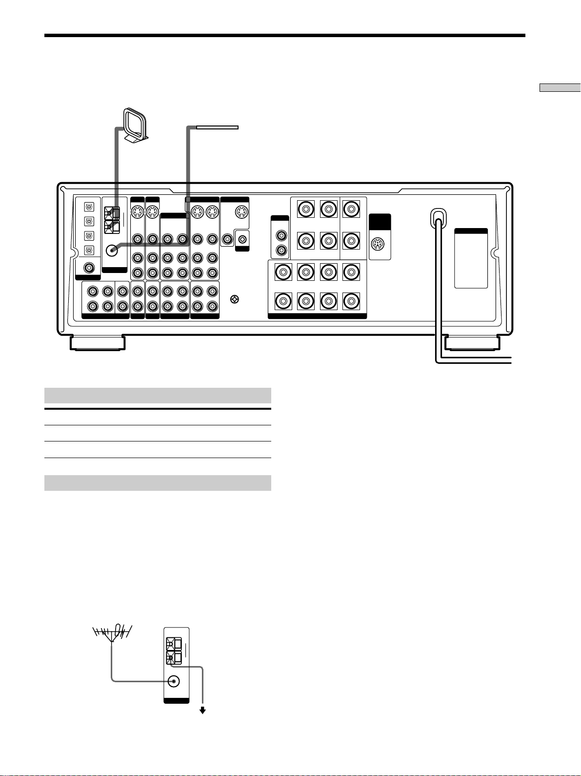
Antenna Hookups
AM loop antenna
(supplied)
FM wire antenna
(supplied)
Hooking Up the Components
TAPE
S-VIDEO
IN
VIDEO
AUDIO
IN
IN
MONITOR
OUT
VIDEO
L
R
L
R
SIGNAL
y
GND
S-VIDEO
OUT
CTRL A1
S-LINK
OPT DVD IN
OPT TV/LD IN
OPT MD/DAT IN
OPT MD/DAT OUT
DVD IN
COAX
DIGITAL
FRONT
L
R
COAXIAL
ANTENNA
REAR CENTER
5.1 INPUT
FM
75Ω
WOOFER
AM
y
TV/LD DVD
S-VIDEO
S-VIDEO
IN
VIDEO
AUDIO
IN
IN
PHONOINCD
VIDEO
AUDIO
VIDEO 1
VIDEO 2
S-VIDEO
OUT
VIDEO
AUDIO
OUT
MD/DAT
VIDEO
AUDIO
IN
OUT
VIDEO
AUDIO
OUT
IN
RECOUT
INRECOUT
IN
IN
Terminals for connecting the antennas
Connect the To the
AM loop antenna AM terminals
FM wire antenna FM 75Ω COAXIAL terminal
Notes on antenna hookups
• To prevent noise pickup, keep the AM loop antenna
away from the receiver and other components.
• Be sure to fully extend the FM wire antenna.
• After connecting the FM wire antenna, keep it as
horizontal as possible.
WOOFER
AUDIO
OUT
A
+
R
B
+
RL
–
REAR CENTER
FRONT
SPEAKERS
–
+–
+
WIRELESS
REAR
SPEAKER
–
A
L
B
Important
If you connect the receiver to an outdoor antenna, ground
it against lightning. To prevent a gas explosion, do not
connect the ground wire to a gas pipe.
Note
Do not use the SIGNAL GND y terminal for grounding the
receiver.
AC OUTLET
z
If you have poor FM reception
Use a 75-ohm coaxial cable (not supplied) to connect the receiver
to an outdoor FM antenna as shown below.
Outdoor FM antenna Receiver
AM
y
FM
75Ω
COAXIAL
Ground wire
(not supplied)
ANTENNA
To ground
GB
5
Page 6

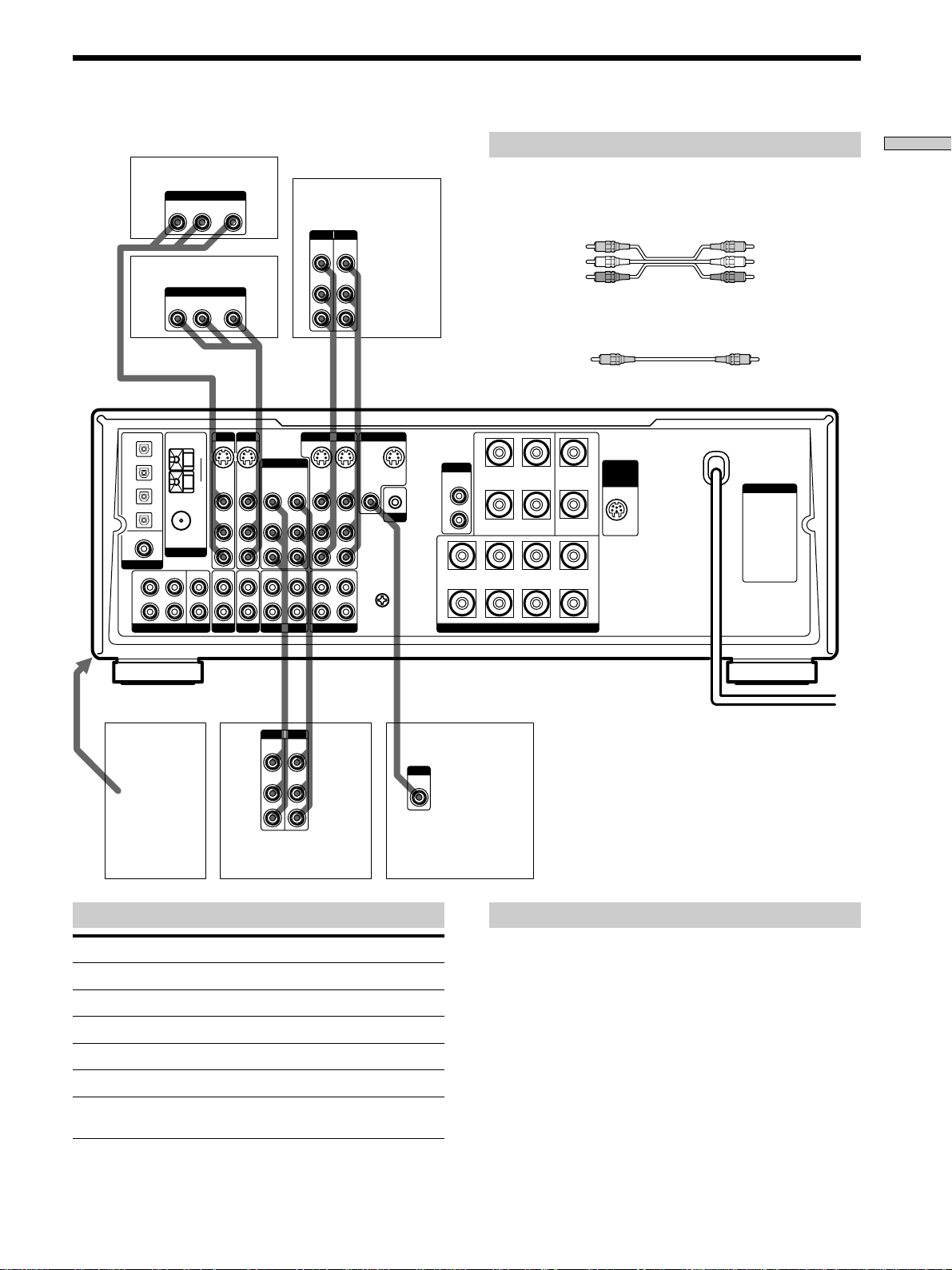
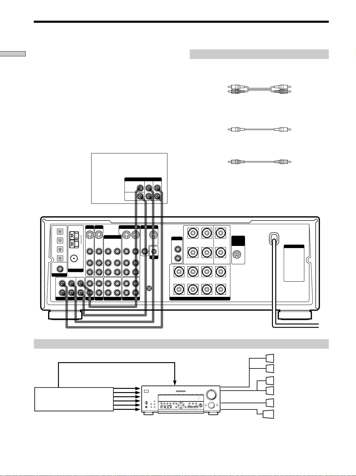
Audio Component Hookups
Hooking Up the Components
Turntable
FM
75Ω
COAXIAL
ANTENNA
REAR CENTER
WOOFER
AM
y
TV/LD DVD
S-VIDEO
S-VIDEO
IN
VIDEO
AUDIO
IN
IN
PHONOINCD
VIDEO
AUDIO
OPT DVD IN
OPT TV/LD IN
OPT MD/DAT IN
OPT MD/DAT OUT
DVD IN
COAX
DIGITAL
FRONT
L
R
5.1 INPUT
MD/DAT deck
INPUT OUTPUT
LINE
LINE
IN OUT
ç
VIDEO 2
OUT
IN
VIDEO
VIDEO
AUDIO
AUDIO
OUT
IN
MD/DAT
IN
IN
INRECOUT
L
R
ç
VIDEO 1
S-VIDEO
OUT
VIDEO
AUDIO
OUT
RECOUT
S-VIDEO
IN
VIDEO
AUDIO
IN
IN
TAPE
ç
MONITOR
OUT
VIDEO
L
R
L
R
SIGNAL
GND
y
S-VIDEO
OUT
CTRL A1
S-LINK
Required cords
Audio cords (not supplied)
When connecting a cord, be sure to match the color-coded pins to
the appropriate jacks on the components.
White (L) White (L)
Red (R) Red (R)
WOOFER
AUDIO
OUT
A
+
R
B
+
RL
–
REAR CENTER
FRONT
SPEAKERS
–
+–
+
WIRELESS
REAR
SPEAKER
–
A
L
B
AC OUTLET
IN OUT
ç
OUTPUT
LINE
L
R
CD player
Jacks for connecting audio components
Connect a To the
Turntable PHONO jacks
CD player CD jacks
Tape deck TAPE jacks
MD deck or DAT deck MD/DAT jacks
Note on audio component hookups
If your turntable has a ground wire, connect it to the
SIGNAL GND y terminal on the receiver.
INPUT OUTPUT
LINE
LINE
Tape deck
L
R
GB
6
Page 7
Video Component Hookups
TV tuner or LD player
OUTPUT
AUDIO OUT VIDEO
RL
DVD player
OUTPUT
AUDIO OUT VIDEO
RL
FM
75Ω
COAXIAL
ANTENNA
REAR CENTER
WOOFER
AM
y
TV/LD DVD
S-VIDEO
IN
VIDEO
AUDIO
IN
IN
PHONOINCD
OPT DVD IN
OPT TV/LD IN
OPT MD/DAT IN
OPT MD/DAT OUT
DVD IN
COAX
DIGITAL
FRONT
L
R
5.1 INPUT
Required cords
Hooking Up the Components
Audio/video cords (not supplied)
When connecting a cord, be sure to match the color-coded pins to
INPUT OUTPUT
VIDEO
VIDEO
OUT
IN
AUDIO
AUDIO
OUT
IN
VCR
L
R
OUT
OUT
the appropriate jacks on the components.
Yellow (video) Yellow (video)
White (L/audio) White (L/audio)
Red (R/audio) Red (R/audio)
Video cord for connecting a TV monitor (not supplied)
IN OUT
ç
Yellow Yellow
ç
S-VIDEO
IN
VIDEO
AUDIO
IN
VIDEO 2
OUT
VIDEO
AUDIO
OUT
MD/DAT
VIDEO
AUDIO
IN
IN
INRECOUT
VIDEO 1
S-VIDEO
OUT
VIDEO
AUDIO
OUT
RECOUT
TAPE
S-VIDEO
IN
VIDEO
AUDIO
IN
IN
MONITOR
OUT
VIDEO
L
R
L
R
SIGNAL
GND
y
S-VIDEO
OUT
CTRL A1
S-LINK
WOOFER
AUDIO
OUT
A
+
R
B
+
RL
–
REAR CENTER
FRONT
SPEAKERS
+
WIRELESS
REAR
SPEAKER
AC OUTLET
–
A
+–
–
L
B
ç
IN
IN
VIDEO
OUT
AUDIO
OUT
VCR
ç
L
R
To the front panel
Camcorder
IN OUT
INPUT OUTPUT
VIDEO
AUDIO
or video
game
Jacks for connecting video components
Connect a To the
TV tuner or LD player TV/LD jacks
VCR VIDEO 1 jacks
Additional VCR VIDEO 2 jacks
DVD player DVD jacks
TV monitor MONITOR VIDEO OUT jack
Camcorder or video game VIDEO 3 INPUT jacks on the
front panel
INPUT
VIDEO
IN
TV monitor
Note on video component hookups
You can connect your TV’s audio output jacks to the TV/
LD AUDIO IN jacks on the receiver and apply sound
effects to the audio from the TV. In this case, do not
connect the TV’s video output jack to the TV/LD VIDEO
IN jack on the receiver. If you are connecting a separate
TV tuner, connect both the audio and video output jacks
to the receiver as shown above.
z
When using the S-video jacks instead of the video jacks
Your monitor must also be connected via an S-video jack. S-video
signals are on a separate bus from the video signals and will not
be output through the video jacks.
GB
7
Page 8
Digital Component Hookups
Hooking Up the Components
Connect the digital output jacks of your DVD player and
TV tuner (etc.) to the receiver’s digital input jacks to bring
the multi channel surround sound of a movie theater into
your home. To enjoy full effect of multi channel surround
sound, five speakers (two front speakers, two rear
speakers, and a center speaker) and a subwoofer are
required. You can also connect an LD player with an RF
OUT jack via an RF demodulator, like the Sony MOD-RF1
(not supplied).
DVD player (etc.)
OUTPUT
VIDEO
OUT
AUDIO
TV/LD DVD
S-VIDEO
S-VIDEO
IN
VIDEO
VIDEO
AUDIO
AUDIO
IN
IN
PHONOINCD
OUT
IN
IN
OUTPUT
DIGITAL
OPTICAL
OPT DVD IN
OPT TV/LD IN
OPT MD/DAT IN
OPT MD/DAT OUT
DVD IN
COAX
DIGITAL
FRONT
L
R
OUTPUT
DIGITAL
COAXIAL
COAXIAL
ANTENNA
REAR CENTER
5.1 INPUT
FM
75Ω
WOOFER
AM
y
TV tuner or LD player
L
R
VIDEO 1
VIDEO 2
OUT
VIDEO
AUDIO
OUT
MD/DAT
VIDEO
AUDIO
S-VIDEO
S-VIDEO
IN
OUT
VIDEO
VIDEO
AUDIO
AUDIO
OUT
IN
RECOUT
INRECOUT
TAPE
Required cords
Optical digital cords (not supplied)
Black Black
Coaxial digital cord (not supplied)
Black Black
Audio/video cords (not supplied)
When connecting a cord, be sure to match the color-coded pins to
the appropriate jacks on the components.
Yellow (video) Yellow (video)
White (L/audio) White (L/audio)
OUTPUT
VIDEO
OUT
AUDIO
OUTPUT
DIGITAL
OPTICAL
OUT
L
R
MONITOR
S-VIDEO
OUT
IN
OUT
VIDEO
CTRL A1
S-LINK
IN
L
R
IN
L
y
R
SIGNAL
GND
WOOFER
A
R
B
Red (R/audio) Red (R/audio)
AUDIO
OUT
+
+
RL
–
REAR CENTER
FRONT
SPEAKERS
–
+–
+
WIRELESS
REAR
SPEAKER
–
A
L
B
AC OUTLET
Example of LD player connected via an RF demodulator
Please note that you cannot connect an LD player’s AC-3 RF OUT jack directly to this unit’s digital input jacks. You must
first convert the RF signal to either an optical or coaxial digital signal. Connect the LD player to the RF demodulator, then
connect the RF demodulator’s optical or coaxial digital output to this unit’s OPTICAL TV/LD IN jack. Refer to the
instruction manual supplied with your RF Demodulator for details on AC-3 RF hookups.
TV/LD
SPEAKERS
A
B
OFF
+
B
A
PHONES
VIDEO IN
VIDEO 1
VIDEO 2 VIDEO 3 DVD TV/LD TAPE MD/DAT CD TUNER PHONO
g
DISPLAY
TUNING/
MEMORY FM MODE
– PTY SELECT +
PRESET TUNING
– +
VIDEO 3 INPUT
SHIFT FM/AM
RLVIDEOS-VIDEO AUDIO
MASTER VOLUME
•
•
MULTI CHANNEL DECODING
EQ
SURROUND
ON/OFF
PTY EON– RDS –
EQUALIZER
INDEX
CURSOR
SET UP
MODE
GENRE MODE ON/OFF
46
•
•
•
3
•
•
•
2
•
•
SOUND FIELD
•
1
EQ
•
•
•
BASS BOOST
0
FUNCTION
5.1
INPUT
INPUT
MODE
BALANCE
•
MODE MUTING
SOUND FIELD
•
•
LR
VIDEO OUT
AC-3 RF
OUT
RF demodulatorLD player
DIGITAL
TV/LD IN
(OPTICAL)
Note
When making connections as shown above, be sure to set INPUT MODE (3 on page 23) manually. This unit may not operate correctly if
INPUT MODE is set to “AUTO.”
GB
8
5
•
•
•
•
•
•
•
7
•
•
•
8
•
•
•
9
•
•
•
10
Page 9
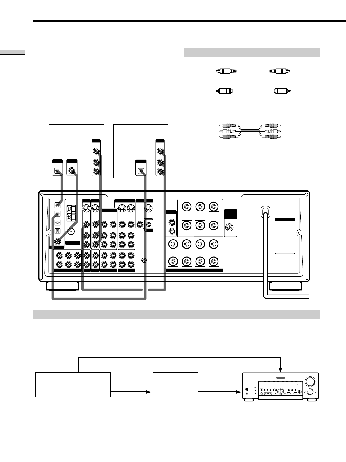
Connect the digital output jack of your MD or DAT deck
to the receiver’s digital input jack and connect the digital
input jack of your MD or DAT deck to the receiver’s
digital output jack. These connections allow you to make
digital recordings of CDs played back through your DVD
(or LD player) and TV broadcasts.
MD or DAT deck
DIGITAL
OPTICAL
OUT
IN
INPUT OUTPUT
LINE
LINE
L
R
Required cords
Optical digital cords (not supplied)
Black Black
Audio cords (not supplied)
When connecting a cord, be sure to match the color-coded pins to
the appropriate jacks on the components.
White (L) White (L)
Red (R) Red (R)
Hooking Up the Components
S-VIDEO
IN
VIDEO
AUDIO
IN
IN
IN OUT
ç
VIDEO 2
OUT
IN
VIDEO
VIDEO
AUDIO
AUDIO
OUT
IN
MD/DAT
IN
IN
INRECOUT
ç
VIDEO 1
S-VIDEO
OUT
VIDEO
AUDIO
OUT
RECOUT
TAPE
S-VIDEO
IN
VIDEO
AUDIO
IN
IN
MONITOR
OUT
VIDEO
L
R
L
y
R
SIGNAL
GND
S-VIDEO
OUT
CTRL A1
S-LINK
WOOFER
AUDIO
OUT
A
+
R
B
+
RL
–
REAR CENTER
FRONT
SPEAKERS
+
WIRELESS
REAR
SPEAKER
AC OUTLET
–
A
+–
–
L
B
OUT IN
ç
OPT DVD IN
OPT TV/LD IN
OPT MD/DAT IN
OPT MD/DAT OUT
DVD IN
COAX
DIGITAL
FRONT
L
R
5.1 INPUT
ç
FM
75Ω
COAXIAL
ANTENNA
REAR CENTER
WOOFER
AM
y
TV/LD DVD
S-VIDEO
VIDEO
AUDIO
PHONOINCD
Notes
• Please note that you cannot make a digital recording of a digital multi channel surround signal.
• To make a digital recording from your CD player, connect the CD player’s digital output directly to the digital input on your MD or DAT
deck. Refer to the instructions supplied with your CD player and MD or DAT deck for details.
• This unit is compatible with 32 kHz, 44.1 kHz, and 48 kHz sampling frequencies. It is not compatible with 96 kHz sampling frequencies.
• It is not possible to record analog signals to TAPE and VIDEO with only digital connections. Be sure to make both digital and analog
connections to your digital components.
GB
9
Page 10
5.1 Input Hookups
Hooking Up the Components
Although this receiver incorporates a multi channel
decoder, it is also equipped with 5.1 INPUT jacks. These
connections allow you to enjoy multi-channel software
encoded in formats other than Dolby Digital (AC-3) and
DTS. If your DVD player is equipped with 5.1 OUTPUT
jacks, you can connect them directly to this unit to enjoy
the sound of the DVD player’s multi channel decoder.
Alternatively, the 5.1 INPUT jacks can be used to connect
an external multi channel decoder.
To fully enjoy multi channel surround sound, you will
need five speakers (two front speakers, two rear speakers,
and a center speaker) and a subwoofer. Refer to the
instruction manual supplied with your DVD player, multi
channel decoder, etc., for details on the 5.1-channel input
hookups.
Multi-channel decoder, etc.
DVD player,
5.1 OUTPUT
CENTER
WOOFER
REAR
Required cords
Audio cords (not supplied)
Two for the 5.1 INPUT FRONT and REAR jacks
White (L) White (L)
Red (R) Red (R)
Monaural audio cords (not supplied)
Two for the 5.1 INPUT CENTER and WOOFER jacks
Black Black
Video cord (not supplied)
One for the DVD VIDEO IN jacks (etc.)
Yellow Yellow
FRONT
VIDEO 2
OUT
VIDEO
AUDIO
OUT
MD/DAT
VIDEO
AUDIO
IN
IN
INRECOUT
VIDEO 1
S-VIDEO
OUT
VIDEO
AUDIO
OUT
RECOUT
TAPE
S-VIDEO
IN
VIDEO
AUDIO
IN
IN
MONITOR
OUT
VIDEO
L
R
L
y
R
SIGNAL
GND
S-VIDEO
OUT
CTRL A1
S-LINK
WOOFER
AUDIO
OUT
A
+
R
B
+
RL
–
REAR CENTER
FRONT
SPEAKERS
–
OPT DVD IN
OPT TV/LD IN
OPT MD/DAT IN
OPT MD/DAT OUT
DVD IN
COAX
DIGITAL
FRONT
L
R
COAXIAL
ANTENNA
REAR CENTER
5.1 INPUT
FM
75Ω
WOOFER
AM
y
TV/LD DVD
S-VIDEO
S-VIDEO
IN
VIDEO
VIDEO
AUDIO
AUDIO
IN
IN
PHONOINCD
IN
IN
Example of a DVD player hookup using the 5.1 INPUT jacks
VIDEO OUT
5.1 INPUT
DVD player
Note
See page 12 for details on speaker system hookup.
VIDEO 1
g
DISPLAY
SPEAKERS
A
B
OFF
A
+B
PRESET TUNING
+
PHONES
SHIFT FM/AM
DVD
IN VIDEO etc.
MULTI CHANNEL DECODING
VIDEO 2 VIDEO 3 DVD TV/LD TAPE MD/DAT CD TUNER PHONO
MEMORY FM MODE
TUNING/
–
+
PTY SELECT
VIDEO 3 INPUT
RLVIDEOS-VIDEO AUDIO
EQ
SURROUND
ON/OFF
PTY EON– RDS –
EQUALIZER
INDEX
CURSOR
SOUND FIELD
SET UP
MODE
GENRE MODE ON/OFF
•
3
•
•
•
2
•
•
SOUND FIELD
•
1
EQ
•
BASS BOOST
5.1
INPUT
INPUT
MODE
BALANCE
•
MODE MUTING
•
•
LR
MASTER VOLUME
5
•
•
•
•
•
•
46
•
•
•
•
0
FUNCTION
+–
•
•
•
7
•
•
•
8
•
•
•
9
•
•
•
10
+
WIRELESS
REAR
SPEAKER
–
A
L
B
SPEAKERS
FRONT
SPEAKERS
REAR/CENTER
WOOFER
AC OUTLET
Front Speaker (L)
Front Speaker (R)
Rear Speaker (L)
Rear Speaker (R)
Center Speaker
Active Woofer
10
GB
Page 11
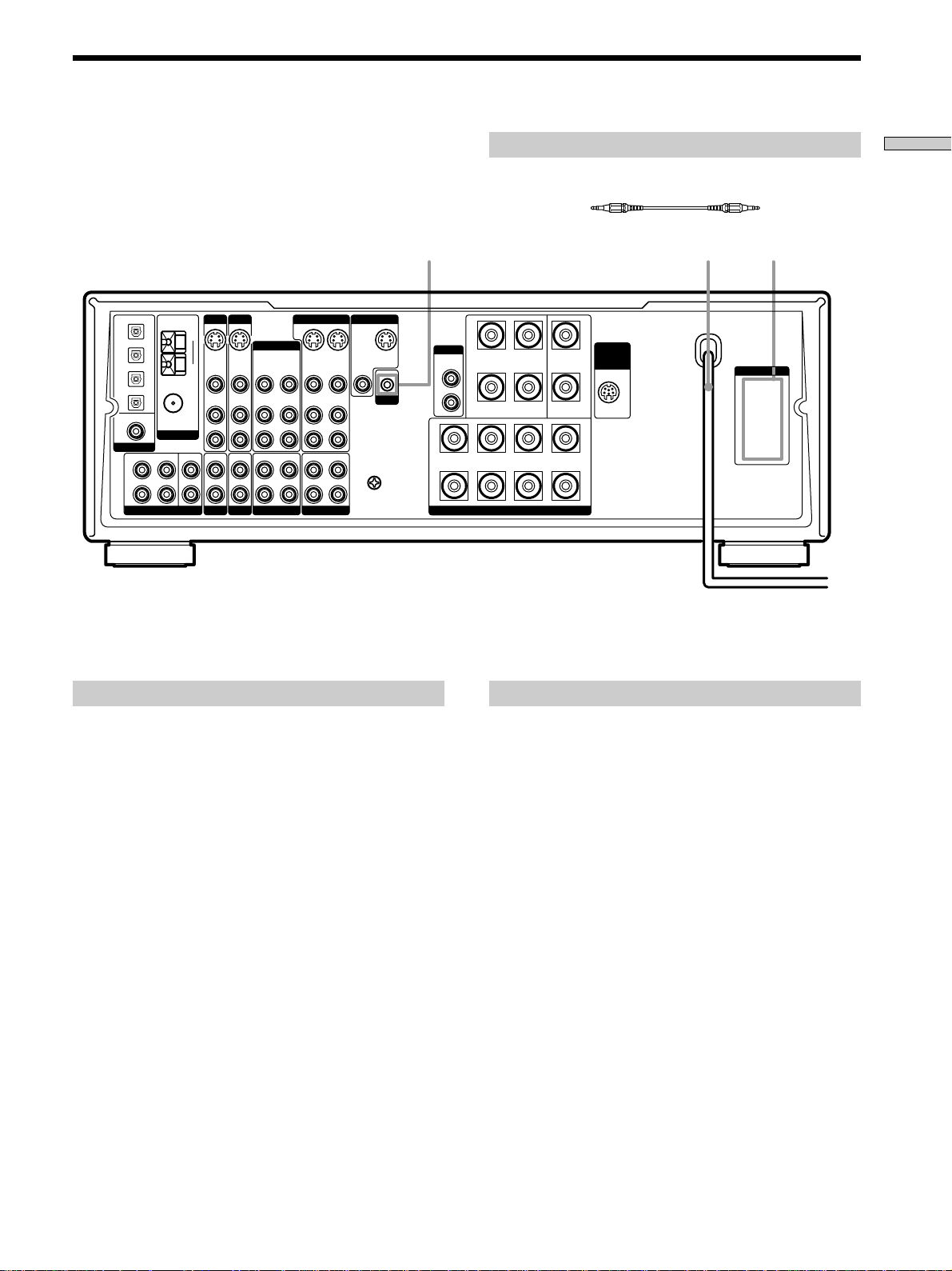
@
Other Hookups
AM
y
FM
75Ω
COAXIAL
ANTENNA
REAR CENTER
WOOFER
TV/LD DVD
S-VIDEO
S-VIDEO
IN
VIDEO
AUDIO
IN
IN
PHONOINCD
VIDEO
AUDIO
IN
IN
OPT DVD IN
OPT TV/LD IN
OPT MD/DAT IN
OPT MD/DAT OUT
DVD IN
COAX
DIGITAL
FRONT
L
R
5.1 INPUT
The configuration, shape, and number of AC outlets on the rear panel
*
VIDEO 2
OUT
VIDEO
AUDIO
OUT
MD/DAT
VIDEO
AUDIO
IN
IN
INRECOUT
VIDEO 1
S-VIDEO
OUT
VIDEO
AUDIO
OUT
RECOUT
TAPE
S-VIDEO
IN
VIDEO
AUDIO
IN
IN
MONITOR
OUT
VIDEO
L
R
L
y
R
SIGNAL
GND
S-VIDEO
OUT
CTRL A1
S-LINK
varies according to the model and country to which the receiver is
shipped.
WOOFER
AUDIO
OUT
A
+
R
B
Required cords
CONTROL A1 connecting cord (not supplied)
Black Black
AC power cord
+
RL
–
REAR CENTER
FRONT
SPEAKERS
–
+–
+
WIRELESS
REAR
SPEAKER
–
A
L
B
Hooking Up the Components
AC OUTLET* @S-LINK CTRL A1
AC OUTLET
b
To a wall outlet
S-LINK CONTROL A1 hookup
• If you have a S-LINK CONTROL A1-compatible
Sony CD player, tape deck, or MD deck
Use a CONTROL A1 cord (not supplied) to connect the
S-LINK CTRL A1 jack on the CD player, tape deck, or
MD deck to the S-LINK CTRL A1 jack on the receiver.
Refer to the separate manual “CONTROL-A1 Control
System” and the operating instructions supplied with
your CD player, tape deck, or MD deck for details.
Note
If you make CONTROL A1 connections from the receiver to an
MD deck that is also connected to a computer, do not operate
the receiver while using the “Sony MD Editor” software. This
may cause a malfunction.
• If you have a Sony CD changer with a
COMMAND MODE selector
If your CD changer’s COMMAND MODE selector can
be set to CD 1, CD 2, or CD 3, be sure to set the
command mode to “CD 1” and connect the changer to
the CD jacks on the receiver.
If, however, you have a Sony CD changer with VIDEO
OUT jacks, set the command mode to “CD 2” and
connect the changer to the VIDEO 2 jacks on the
receiver.
Connecting the AC power cord
Before connecting the AC power cord of this receiver to a
wall outlet:
• Connect the speaker system to the receiver (see page
13).
• Turn the MASTER VOLUME control to the leftmost
position (0).
Connect the AC power cord(s) of your audio/video
components to a wall outlet.
If you connect other audio/video components to the AC
OUTLET(s) on the receiver, the receiver will supply power
to the connected component(s), allowing you to turn the
whole system on or off when you turn the receiver on/off.
Caution
Make sure that the total power consumption of the component(s)
connected to the receiver’s AC OUTLET(s) does not exceed the
wattage stated on the rear panel. Do not connect high-wattage
electrical home appliances such as electric irons, fans, or TVs to
this outlet.
11
GB
Page 12
Hooking Up and Setting Up the Speaker System
This chapter describes how to hook
up your speaker system to the
receiver, how to position each speaker,
and how to set up your speakers to
enjoy multi channel surround sound.
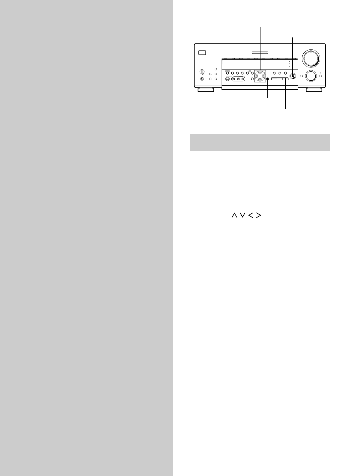
Cursor buttons
BALANCE
MASTER VOLUME
5
•
•
•
•
•
•
46
MULTI CHANNEL DECODING
VIDEO 1
VIDEO 2 VIDEO 3 DVD TV/LD TAPE MD/DAT CD TUNER PHONO
g
DISPLAY
SPEAKERS
A
B
OFF
A
+B
PRESET TUNING
– +
PHONES
SHIFT FM/AM
MEMORY FM MODE
VIDEO 3 INPUT
– PTY SELECT +
TUNING/
RLVIDEOS-VIDEO AUDIO
PTY EON– RDS –
SURROUND
ON/OFF
EQUALIZER
INDEX
CURSOR
SET UP
MODE
EQ
5.1
INPUT
SOUND FIELD
GENRE MODE ON/OFF
SOUND FIELD
EQ
BASS BOOST
INPUT
MODE
BALANCE
•
•
•
LR
•
•
•
•
•
3
•
•
•
2
•
•
•
1
•
•
•
•
0
10
FUNCTION
MODE MUTING
•
•
•
SET UP
SOUND FIELD
ON/OFF
Brief descriptions of buttons and controls
used to set up the speaker system
SET UP button: Press repeatedly to display “SPEAKER
SETUP” when specifying speaker types or “SPEAKER
DISTANCE” when specifying speaker distances.
SOUND FIELD ON/OFF button: Turns the sound field
mode on or off.
7
•
•
•
8
•
•
•
9
Cursor buttons (
/ / / ): Use to select the
parameters and settings after pressing the SET UP button.
BALANCE control: Use to adjust the front speaker
balance while outputting a test tone.
12
GB
Page 13
Speaker System Hookup
Required cords
Speaker cords (not supplied)
One for each front, rear, and center speaker
(+) (+)
(–) (–)
Monaural audio cord (not supplied)
One for an active woofer
Rear speaker (R) Rear speaker (L)
}
]
}
]
Center speaker
}
]
Hooking Up and Setting Up the Speaker System
Black Black
OUT
VIDEO
AUDIO
OUT
INPUT
AUDIO
IN
VIDEO 2
MD/DAT
VIDEO
AUDIO
IN
IN
INRECOUT
VIDEO 1
S-VIDEO
OUT
VIDEO
AUDIO
OUT
RECOUT
TAPE
S-VIDEO
IN
VIDEO
AUDIO
IN
IN
MONITOR
OUT
VIDEO
L
R
L
R
OPT DVD IN
OPT TV/LD IN
OPT MD/DAT IN
OPT MD/DAT OUT
DVD IN
COAX
DIGITAL
FRONT
L
R
COAXIAL
ANTENNA
REAR CENTER
5.1 INPUT
FM
75Ω
WOOFER
AM
y
TV/LD DVD
S-VIDEO
S-VIDEO
IN
VIDEO
AUDIO
AUDIO
IN
IN
PHONOINCD
VIDEO
IN
IN
Active woofer Front speaker (R)
y
SIGNAL
GND
}
S-VIDEO
OUT
CTRL A1
S-LINK
WOOFER
AUDIO
OUT
A
+
R
B
]
+
RL
–
REAR CENTER
FRONT
SPEAKERS
FRONT
SPEAKERS B
WIRELESS
REAR SPEAKER
+–
–
+
WIRELESS
REAR
SPEAKER
–
A
L
B
}
Front speaker (L)
AC OUTLET
]
Terminals for connecting the speakers
Connect the To the
Front speakers (4~16* ohm) SPEAKERS FRONT A terminals
Additional pair of front
speakers (4~16* ohm)
Rear speakers (4~16 ohm) SPEAKERS REAR terminals
Center speaker (4~16 ohm) SPEAKERS CENTER terminals
Active woofer WOOFER AUDIO OUT jack**
Wireless rear speaker
transmitter
SPEAKERS FRONT B terminals
WIRELESS REAR SPEAKER jack
* Be sure to connect front speakers with a nominal impedance of 8
ohms or higher if you want to select both sets (A+B) of front speakers
(see page 23).
** You can connect an active woofer to either of the two jacks. The
remaining jack can be used to connect a second active woofer.
13
GB
Page 14
Speaker System Hookup
Multi-Channel Surround Setup
Notes on speaker system hookup
• Twist the stripped ends of the speaker cords about 2/3
inch (15 mm). Be sure to match the speaker cord to the
Hooking Up and Setting Up the Speaker System
appropriate terminal on the components: + to + and –
to –. If the cords are reversed, the sound will be
distorted and will lack bass.
• If you use front speakers with low maximum input
rating, adjust the volume carefully to avoid excessive
output on the speakers.
• The WIRELESS REAR SPEAKER jack is for use with
Sony wireless rear speaker systems only, do not connect
any other speaker systems or components to this jack.
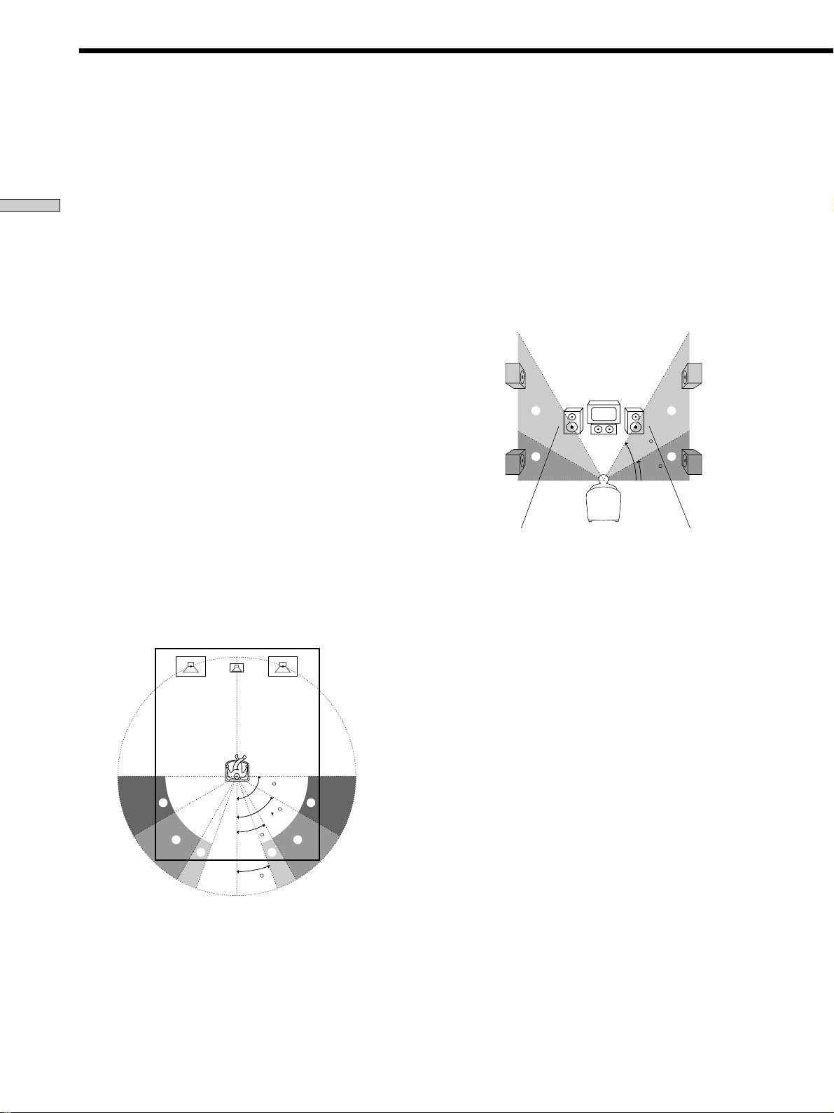
For the best possible surround sound all speakers should
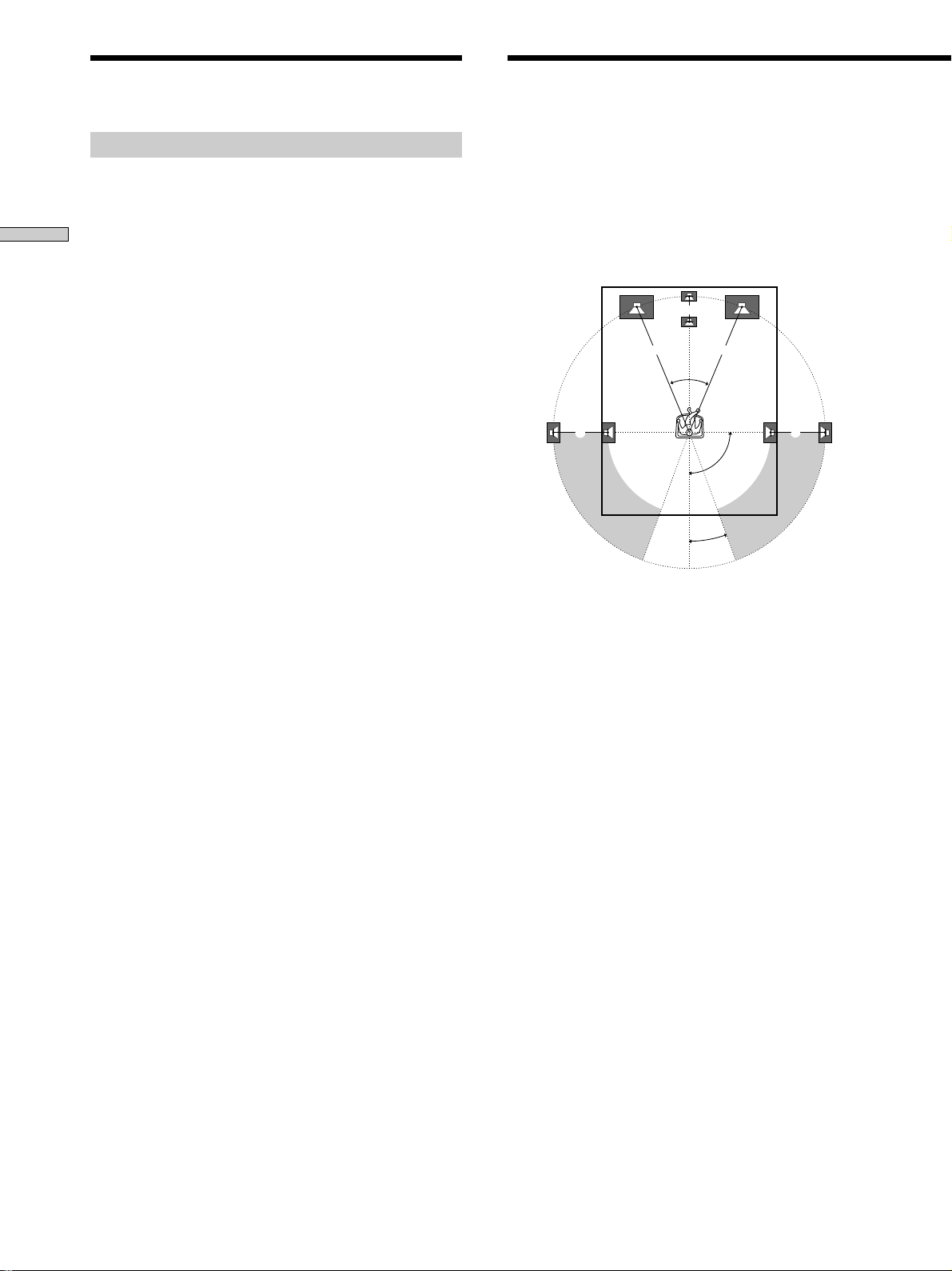
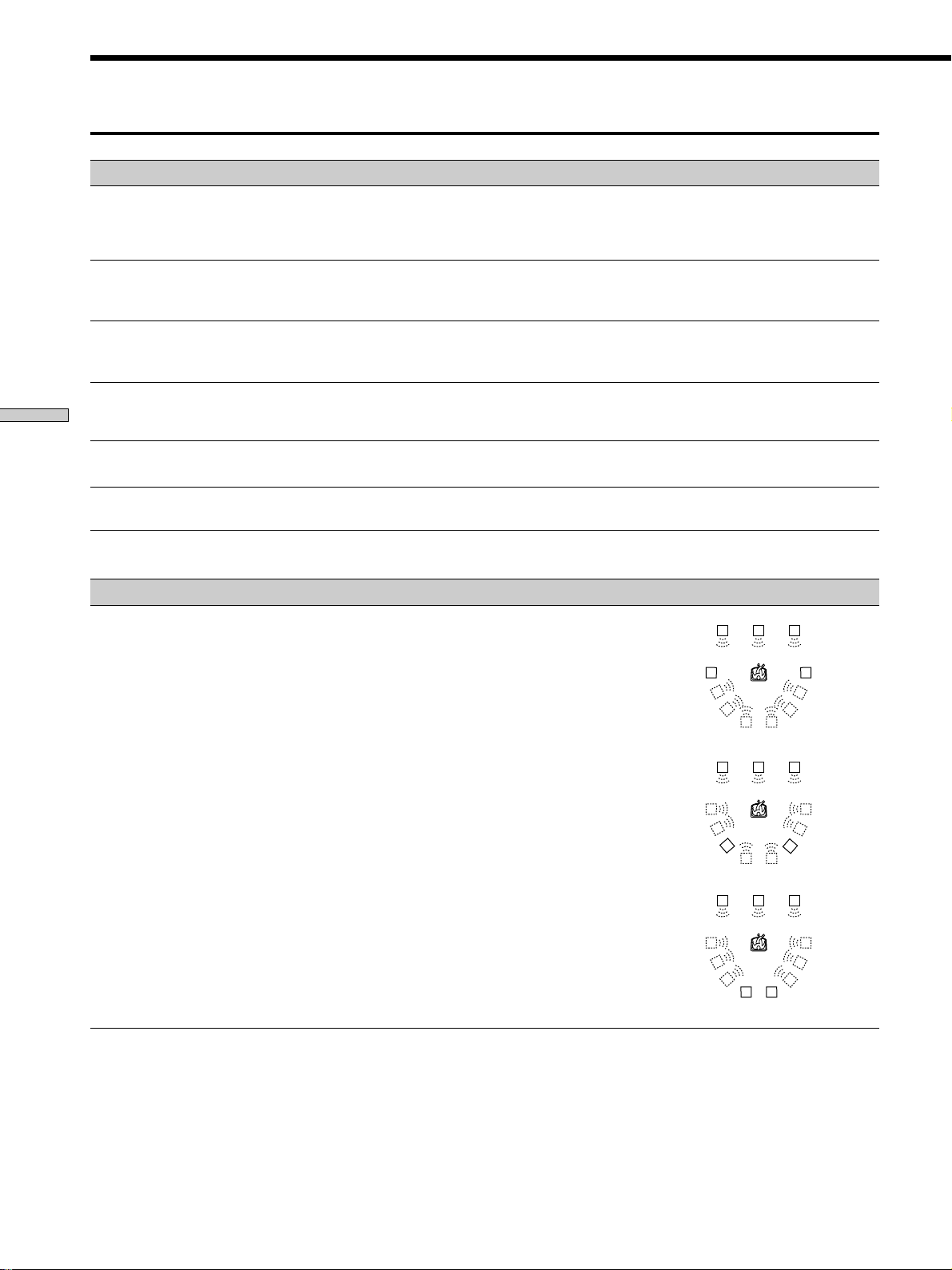
be the same distance from the listening position (A).
(However, this unit lets you to place the center speaker up
to 1.5 meters (5 feet) closer (B) and the rear speakers up
to 4.5 meters (15 feet) closer (C) to the listening position.
The front speakers can be placed from 1.0 to 12.0 meters (3
to 40 feet) from the listening position (A).)
B
A A
45°
CC
90°
20°
Note
Do not place the center or rear speakers farther away from the
listening position than the front speakers.
14
GB
Page 15
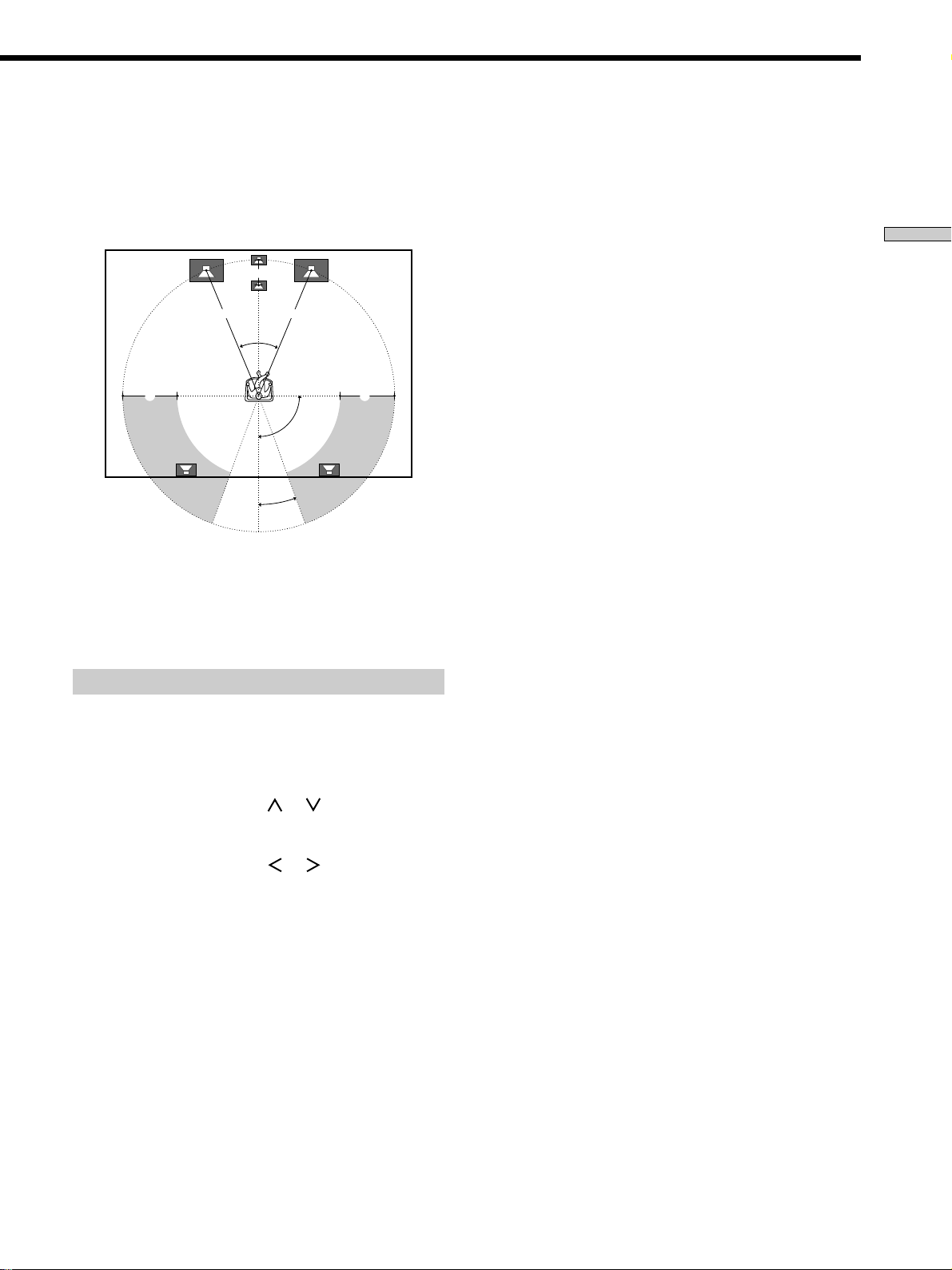
Depending on the shape of your room (etc.), you may
wish to place the rear speakers behind you instead of on
the side walls. One advantage of this placement is that
you can use a pair of large floor standing speakers
matching your front speakers.
B
A A
45°
CC
90°
20°
Note
If you place the rear speakers behind you, be sure to check the
speaker location setting in the SPEAKER SETUP menu when
using sound fields from the VIRTUAL 3D genre (see pages 16
and 28~29 for details).
Specifying the speaker types
p Front speaker size (FRONT)
Initial setting : LARGE
• If you connect large speakers that will effectively
reproduce bass frequencies, select “LARGE”. Normally,
select “LARGE”.
• If the sound is distorted, or you feel a lack of surround
effects when using multi-channel surround sound,
select “SMALL” to activate the bass redirection circuitry
and output the front channel bass frequencies from the
sub woofer.
• When the front speaker is set to “SMALL”, the center
and rear speakers are also automatically set to
“SMALL” (unless previously set to “NO”).
p Center speaker size (CENTER)
Initial setting : LARGE
• If you connect a large speaker that will effectively
reproduce bass frequencies, select “LARGE”. Normally,
select “LARGE”. However, if the front speakers are set
to “SMALL”, you cannot set the center speaker to
“LARGE”.
• If the sound is distorted, or you feel a lack of surround
effects when using multi-channel surround sound,
select “SMALL” to activate the bass redirection circuitry
and output the center channel bass frequencies from the
front speakers (if set to “LARGE”) or sub woofer. *
1
• If you do not connect the center speaker, select “NO”.
The sound of the center channel will be output from the
front speakers.*
2
Hooking Up and Setting Up the Speaker System
1 Press 1/u to turn on the receiver.
2 Press SET UP to display “SPEAKER SETUP”.
3 Press the cursor buttons ( or ) to select the
parameter you want to adjust.
4 Press the cursor buttons ( or ) to select setting
you desire. The setting is entered automatically.
5 Repeat steps 3 and 4 until you have set all of the
parameters that follow.
p Rear speaker size (REAR)
Initial setting : LARGE
• If you connect large speakers that will effectively
reproduce bass frequencies, select “LARGE”. Normally,
select “LARGE”. However, if the front speakers are set
to “SMALL”, you cannot set the rear speakers to
“LARGE”.
• If the sound is distorted, or you feel a lack of surround
effects when using multi-channel surround sound,
select “SMALL” to activate the bass redirection circuitry
and output the rear channel bass frequencies from the
sub woofer or other “LARGE” speakers.
• If you do not connect rear speakers, select “NO”.*
z
*1~*3 correspond to the following Dolby Pro Logic modes
*1 NORMAL
*2 PHANTOM
*3 3 STEREO
3
15
GB
Page 16
Multi-Channel Surround Setup
z
About speaker sizes (LARGE and SMALL)
Internally, the LARGE and SMALL settings for each speaker
determine whether or not the internal sound processor will cut
the bass signal from that channel. When the bass is cut from a
channel, the bass redirection circuitry sends the corresponding
bass frequencies to the sub woofer or other “LARGE” speaker.
Hooking Up and Setting Up the Speaker System
However, since bass sounds have a certain amount of
directionality it best not to cut them, if possible. Therefore, even
when using small speakers, you can set them to “LARGE” if you
want to output the bass frequencies from that speaker. On the
other hand, if you are using a large speaker, but prefer not to
have bass frequencies output from that speaker, set it to
“SMALL”.
If the overall sound level is lower than you prefer, set all speakers
to “LARGE”. If there is not enough bass, you can use the
equalizer to boost the bass levels. To set the equalizer, see page
34.
p Rear speaker height (REAR HGT.)*
Initial setting : LOW
This parameter lets you specify the height of your rear
speakers for proper implementation of the Digital Cinema
Sound surround modes in the VIRTUAL 3D genre. Refer
to the illustration below.
• Select “LOW” if the location of your rear speakers
corresponds to section A.
• Select “HIGH” if the location of your rear speakers
corresponds to section B.
This setting only effects the surround modes in the
VIRTUAL 3D genre.
p Rear speaker position (REAR PL.)*
Initial setting : BEHIND
This parameter lets you specify the location of your rear
speakers for proper implementation of the Digital Cinema
Sound surround modes in the VIRTUAL 3D genre. Refer
to the illustration below.
• Select “SIDE” if the location of your rear speakers
corresponds to section A.
• Select “MIDDLE” if the location of your rear speakers
corresponds to section B.
• Select “BEHIND” if the location of your rear speakers
corresponds to section C.
This setting only effects the surround modes in the
VIRTUAL 3D genre.
90
A
B
30
C C
20
60
A
B
B
B
60
A
A
30
* These parameters are not available when “Rear speaker
size (REAR)“ is set to “NO”.
z
About the rear speaker position (SIDE, MIDDLE, and BEHIND)
This setting is designed specifically for implementation of the
Digital Cinema Sound modes in the VIRTUAL 3D genre.
With the Digital Cinema Sound modes, speaker position is not as
critical as other modes. All of the modes in the VIRTUAL 3D
genre were designed under the premise that the rear speaker
would be located behind the listening position, but presentation
remains fairly consistent even with the rear speakers positioned
at a rather wide angle. However, if the speakers are pointing
toward the listener from the immediate left and right of the
listening position, the VIRTUAL 3D modes will not be effective
unless the rear speaker position parameter is set to “SIDE”.
Nevertheless, each listening environment has many variables,
like wall reflections, and you may obtain better results using
“BEHIND” or “MIDDLE” if your speakers are located high above
the listening position, even if they are to the immediate left and
right.
Therefore, although it may result in a setting contrary to the
“Rear speaker position” explanation, we recommend that you
playback multi channel surround encoded software and listen to
the effect each setting has on your listening environment. Choose
the setting that provides a good sense of spaciousness and that
best succeeds in forming a cohesive space between the surround
sound from the rear speakers and the sound of the front speakers.
If you are not sure which sounds best, select “BEHIND” and then
use the speaker distance parameter and speaker level
adjustments to obtain proper balance.
16
GB
Page 17

p Sub woofer selection (WOOFER)
Initial setting : YES
• If you connect a sub woofer, select “YES”.
• If you do not connect a sub woofer, select “NO”. This
activates the Dolby Digital (AC-3) bass redirection
circuitry and outputs the LFE signals from other
speakers.
• In order to take full advantage of the Dolby Digital (AC-
3) bass redirection circuitry, we recommend setting the
sub woofer’s cut off frequency as high as possible.
Specifying the speaker distances
p Rear speaker distance (REAR)
Initial setting : 3.5 meter
Set the distance from your listening position to the rear
(left or right) speaker.
• Rear speaker distance can be set in 0.1 meter (1 foot)
steps from a distance equal to the front speaker distance
(A on page 14) to a distance 4.5 meters (15 feet) closer
to your listening position (C on page 14).
• Do not place the rear speakers farther away from your
listening position than the front speakers.
• If both speakers are not placed an equal distance from
your listening position, set the distance to the closest
speaker.
Hooking Up and Setting Up the Speaker System
1 Press SET UP to display “SPEAKER DISTANCE”.
2 Press the cursor buttons ( or ) to select the
parameter you want to adjust.
3 Press the cursor buttons ( or ) to select setting
you desire. The setting is entered automatically.
4 Repeat steps 2 and 3 until you have set all of the
parameters described below.
5 Press SET UP to exit the set up mode.
p Front speaker distance (FRONT)
Initial setting : 5.0 meter
Set the distance from your listening position to the front
(left or right) speaker (A on page 14).
• Front speaker distance can be set in 0.1 meter (1 foot)
steps from 1.0 to 12.0 meters (3 to 40 feet).
• If both speakers are not placed an equal distance from
your listening position, set the distance to the closest
speaker.
p Center speaker distance (CENTER)
Initial setting : 5.0 meter
Set the distance from your listening position to the center
speaker.
• Center speaker distance can be set in 0.1 meter (1 foot)
steps from a distance equal to the front speaker distance
(A on page 14) to a distance 1.5 meters (5 feet) closer to
your listening position (B on page 14).
• Do not place the center speaker farther away from your
listening position than the front speakers.
z
About speaker distances
This unit allows you to input the speaker position in terms of
distance. However, it is not possible to set the center speaker
farther away than the front speakers. Also, the center speaker can
not be set more than 1.5 meters (5 feet) closer than the front
speakers.
Likewise, the rear speakers can not be set farther away from the
listening position than the front speakers. And they can be no
more than 4.5 meters (15 feet) closer.
This is because incorrect speaker placement is not conducive to
the enjoyment of surround sound.
Please note that, setting the speaker distance closer than the
actual location of the speakers will cause a delay in the output of
the sound from that speaker. In other words, the speaker will
sound like it is farther away.
For example, setting the center speaker distance 1~2 m (3~6 feet)
closer than the actual speaker position will create a fairly realistic
sensation of being “inside” the screen. If you cannot obtain a
satisfactory surround effect because the rear speakers are too
close, setting the rear speaker distance closer (shorter) than the
actual distance will create a larger soundstage.
Adjusting these parameter while listening to the sound often
results in much better surround sound. Give it a try!
p Distance unit (DIST. UNIT)
Initial setting : METER
Lets you select either feet or meters as the unit of measure
for setting distances. 1 foot corresponds to a 1 ms
difference.
17
GB
Page 18

Multi-Channel Surround Setup
Adjusting the speaker volume
Use the remote while seated in your listening position to
adjust the volume of each speaker.
Note
Hooking Up and Setting Up the Speaker System
This unit incorporates a new test tone with a frequency centered
at 800 Hz for easier speaker volume adjustment.
1 Press 1/u to turn on the receiver.
2 Press TEST TONE on the supplied remote.
You will hear the test tone from each speaker in
sequence.
3 Adjust the volume level so that the volume of the
test tone from each speaker sounds the same
when you are in your main listening position.
• To adjust the balance of the front right and front left
speakers, use the BALANCE control on the front of
the receiver.
• To adjust the balance of the rear right and rear left
speakers, use the REAR BALANCE parameter in the
SURROUND cursor mode (see pages 33 and 34).
(The rear balance can also be adjusted from the
remote.)
• To adjust the volume level of the center speaker,
press the LEVEL CENTER +/– buttons on the
remote.
• To adjust the volume level of the rear speakers, press
the LEVEL REAR +/– buttons on the remote.
Notes
• The rear balance, center level, and rear level are shown in the
display during adjustment.
• Although these adjustments can also be made via the front
panel using the CURSOR MODE menu SURROUND
parameters (when the test tone is output, the CURSOR MODE
switches to the SURROUND parameters automatically), we
recommend you follow the procedure described above and
adjust the speaker levels from your listening position using the
remote control.
z
When setting the volume levels for each speaker
Let’s assume that you have matched the sound levels of all the
speakers using the test tone. Although this lays the foundation
for high quality surround sound, it may be necessary to make
further adjustments while listening to playback of actual
software. This is because most software contains center and rear
channels recorded at slightly lower levels than the two front
channels.
When you actually playback software recorded in multi channel
surround you will notice that increasing the center and rear
speaker levels produces a better blend between the front and
center speakers and greater cohesion between the front and rear
speakers. Increasing the level of the center speaker about 1 dB,
and the rear speakers about 1~2 dB is likely to produce better
results.
In other words, in order to create a more cohesive soundstage
with balanced dialog, we recommend that you make some
adjustments while playing your software. Changes of only 1 dB
can make a huge difference in the character of the soundstage.
4 Press TEST TONE on the remote again to turn off
the test tone.
z
You can adjust the volume level of all speakers at the same
time
Rotate MASTER VOLUME on the main unit or press MASTER
VOLUME +/– on the remote.
18
GB
Page 19
Before You Use Your Receiver
Before turning on the receiver
Make sure that you have:
• Turned MASTER VOLUME to the leftmost position (0).
• Selected the appropriate front speakers (see “8
SPEAKERS selector” on page 23).
• Set BALANCE to the center position.
Clearing the receiver’s memory
Before you use your receiver for the first time or when
you want to clear the receiver’s memory, do the following.
1/u
MULTI CHANNEL DECODING
SOUND FIELD
ON/OFF
EQ
5.1
SURROUND
ON/OFF
INPUT
EQUALIZER
INDEX
SOUND FIELD
SET UP
GENRE MODE ON/OFF
INPUT
MODE
SOUND FIELD
EQ
BASS BOOST
BALANCE
•
•
•
LR
MASTER VOLUME
5
•
•
•
•
•
•
46
•
•
•
•
3
•
•
•
2
•
•
•
1
•
•
•
•
0
10
FUNCTION
MODE MUTING
•
•
7
•
•
9
•
•
•
•
8
•
•
SPEAKERS
OFF
A
+B
PHONES
DISPLAY
A
B
SHIFT FM/AM
PRESET TUNING
– +
VIDEO 1
VIDEO 2 VIDEO 3 DVD TV/LD TAPE MD/DAT CD TUNER PHONO
g
DISPLAY
MEMORY FM MODE
VIDEO 3 INPUT
– PTY SELECT +
TUNING/
PTY EON– RDS –
CURSOR
MODE
RLVIDEOS-VIDEO AUDIO
1 Turn off the receiver.
Checking the connections
After connecting all of your components to the receiver,
do the following to verify that the connections were made
correctly.
1/u
MASTER VOLUME
MASTER VOLUME
5
•
•
•
•
•
•
46
MULTI CHANNEL DECODING
VIDEO 1
VIDEO 2 VIDEO 3 DVD TV/LD TAPE MD/DAT CD TUNER PHONO
g
DISPLAY
SPEAKERS
A
B
OFF
A
+
B
PRESET TUNING
– +
PHONES
SHIFT FM/AM
MEMORY FM MODE
VIDEO 3 INPUT
– PTY SELECT +
TUNING/
RLVIDEOS-VIDEO AUDIO
PTY EON– RDS –
SURROUND
EQUALIZER
INDEX
CURSOR
SET UP
MODE
EQ
5.1
ON/OFF
INPUT
SOUND FIELD
GENRE MODE ON/OFF
SOUND FIELD
EQ
BASS BOOST
INPUT
MODE
BALANCE
•
•
•
LR
•
•
•
•
•
3
•
•
•
2
•
•
•
1
•
•
•
•
•
0
10
FUNCTION
MODE MUTING
FUNCTION
•
7
•
•
•
8
•
•
•
9
•
1 Press 1/u to turn on the receiver.
2 Rotate FUNCTION to select a component (program
source) that you connected (e.g., CD player or tape
deck).
Hooking Up and Setting Up the Speaker System
2 While pressing down DISPLAY and SOUND FIELD
ON/OFF, press 1/u to turn on the receiver.
The demonstration appears in the display and the
items including the following are reset or cleared:
• All preset stations are reset or cleared.
• All sound field parameters are reset to their factory
settings.
• All index names (of preset stations and program
sources) are cleared.
• All adjustments made with the SET UP button are
reset to their factory settings.
• The sound field memorized for each program source
and preset stations are cleared.
3 Turn on the component and start playing it.
4 Rotate MASTER VOLUME to turn up the volume.
If you do not obtain normal sound output after
performing this procedure, look for the reason in the
following checklist and take the appropriate measures to
correct the problem.
There is no sound no matter which component is
selected.
/ Check that both the receiver and all components
are turned on.
/ Check that the MASTER VOLUME control is not
set at 0.
/ Check that the SPEAKERS selector is not set to
OFF or to a position for front speakers that are not
connected to the receiver (see “8 SPEAKERS
selector” on page 23).
/ Check that all speaker cords are connected
correctly.
/ Press the MUTING button to turn off the indicator
to the left of the button.
19
GB
Page 20

Before You Use Your Receiver
There’s no sound from a specific component.
/ Check that the component is connected correctly to
the audio input jacks for that component.
/ Check that the cord(s) used for the connection is
(are) fully inserted into the jacks on both the
Hooking Up and Setting Up the Speaker System
receiver and the component.
No sound is heard from one of the front
speakers.
/ Check that the BALANCE control is set at center
position (see “7 BALANCE control” on page 23).
/ Connect a pair of headphones to the PHONES jack
and set the SPEAKERS selector to OFF to verify
that sound is output from the headphones (see “8
SPEAKERS selector” and “PHONES jack” on page
23).
If only one channel is output from the headphones,
the component may not be connected to the
receiver correctly. Check that all the cords are fully
inserted into the jacks on both the receiver and the
component.
If both channels are output from the headphones,
the front speaker may not be connected to the
receiver correctly. Check the connection of the
front speaker which is not outputting any sound.
If you encounter a problem that is not included above, see
“Troubleshooting” on page 47.
20
GB
Page 21

Hooking Up and Setting Up the Speaker System
21
GB
Page 22

Location of
Parts and Basic
Front Panel Parts Description
Operations
This chapter provides information
about the locations and functions of
the buttons and controls on the front
panel. It also explains basic
operations.
1 1/u switch
Press to turn the receiver on and off.
• Before you turn on the receiver, make sure that you have
turned the MASTER VOLUME control to the leftmost
position to avoid damaging you speakers.
2 FUNCTION control
Rotate to select the component you want to use.
To select Rotate to light
VCR VIDEO 1 or VIDEO 2
Camcorder or video game VIDEO 3
TV tuner or LD player TV/LD
DVD player DVD
Tape deck TAPE
MD or DAT deck MD/DAT
CD player CD
Built in tuner TUNER
Turntable PHONO
After selecting the component, turn on the component
you selected and play the program source.
22
GB
• After selecting VCR, camcorder, video game, DVD player,
or LD player, turn on the TV and set the TV’s video input.
• When using digital inputs, there may be up to 6 seconds of
silence when switching functions or inserting new discs.
MODE button
Press to select and play another video/audio source in
combination with the selected component.
Each time you press the button, the display changes as
follows:
n V:XXX n A:XXX n selected component
Press MODE to display And rotate FUNCTION to select
V:XXX Any video source to enjoy with
the audio from the selected
component
A:XXX Any audio source to enjoy with
the video from the selected
component
• When the 5.1 INPUT (4) is selected, MODE displays
“V:XXX” only.
z Function indicators
Normally, the indicator above the selected function lights orange.
However, when MODE is used to select a different video (V:XXX)
or audio (A:XXX) source, the video function lights green and the
audio function lights orange. This also occurs when you select
audio components (like PHONO).
Page 23
EQUALIZER
INDEX
SET UP
4
EQ
5.1
INPUT
SOUND FIELD
INPUT
MODE
ON/OFF
GENRE MODE ON/OFF
SOUND FIELD
EQ
BASS BOOST
BALANCE
•
•
•
LR
MASTER VOLUME
•
46
•
•
•
3
•
•
•
2
•
•
•
1
•
•
•
0
MODE MUTING
1 5
MULTI CHANNEL DECODING
VIDEO 1
VIDEO 2 VIDEO 3 DVD TV/LD TAPE MD/DAT CD TUNER PHONO
g
+
A
SPEAKERS
OFF
B
PHONES
A
B
DISPLAY
PRESET TUNING
– +
SHIFT FM/AM
MEMORY FM MODE
VIDEO 3 INPUT
TUNING/
+
– PTY SELECT
RLVIDEOS-VIDEO AUDIO
PTY– –EON RDS
CURSOR
MODE
SURROUND
•
•
FUNCTION
5
•
•
•
•
•
•
7
•
•
•
8
•
•
•
9
•
•
•
10
Location of Parts and Basic Operations
8
3 INPUT MODE button
Press to select the input mode for your digital
components (DVD, TV/LD and MD/DAT).
Each press switches the input mode of the currently
selected component.
Select To
AUTO Give priority to digital signals
when there are both digital and
analog connections. If there are
no digital signals, analog is
selected
ANALOG Specify the analog audio signals
input to the AUDIO IN (L and R)
jacks
DIGITAL (OPTICAL) Specify the digital audio signals
input to the DIGITAL OPTICAL
input jacks
DIGITAL (COAXIAL) Specify the digital audio signals
input to the DIGITAL COAXIAL
input jack (DVD only)
4 5.1 INPUT button
Press to enjoy the audio source connected to the 5.1
INPUT jacks with the video from the selected
component.
To select another video source, use MODE (2).
• When the 5.1 INPUT is selected, the equalizer, bass booster,
and sound field effects do not function.
2 673
5 MASTER VOLUME control
After turning on the component you selected, rotate to
adjust the volume.
6 MUTING button
Press to mute the sound. The indicator above the
button lights up when the sound is muted.
7 BALANCE control
Rotate to adjust the balance of the front speakers.
8 SPEAKERS selector
Set according to the front speakers you want to drive.
Set to To select
A The speakers connected to the FRONT
B The speakers connected to the FRONT
A+B* The speakers connected to both the FRONT
OFF No front speaker output
Do not set to A+B when a sound field is turned on.
*
PHONES jack
Connects headphones.
• To use the headphones, set the SPEAKERS selector to OFF
to output sound to the headphones.
• When the sound field is ON, setting the SPEAKERS
selector to OFF will automatically present a two channel
downmix from the headphones.
SPEAKERS A terminals
SPEAKERS B terminals
SPEAKERS A and B terminals (parallel
connection)
23
GB
Page 24
Front Panel Parts Description
9
VIDEO 1
g
SPEAKERS
A
B
OFF
+B
A
Location of Parts and Basic Operations
PHONES
DISPLAY
PRESET TUNING
– +
SHIFT FM/AM
MEMORY FM MODE
!£
9 DISPLAY button
Press repeatedly to change the information on the
display window as follows:
Index name of the component*
Sound field applied to the component
When the tuner is selected
Index name of the preset station* or program
Program type indication**
Sound field applied to the band or the preset
v
v
Selected component
v
v
station name**
v
Frequency
v
v
Radio text**
v
Current time**
v
station
!¡ !™
MULTI CHANNEL DECODING
VIDEO 2 VIDEO 3 DVD TV/LD TAPE MD/DAT CD TUNER PHONO
SOUND FIELD
EQ
BASS BOOST
EQ
5.1
INPUT
SOUND FIELD
INPUT
MODE
BALANCE
•
•
LR
VIDEO 3 INPUT
TUNING/
– PTY SELECT
SURROUND
PTY EON– RDS –
+
CURSOR
MODE
RLVIDEOS-VIDEO AUDIO
EQUALIZER
INDEX
SET UP
ON/OFF
GENRE MODE ON/OFF
0!§ !¶ !•!¢ !∞
* Index name appears only when you have assigned one to the
component or preset station (see page 45). Index name does not
appear when only blank spaces have been entered, or it is the
same as the function button.
** These indications appear only during RDS reception (see page
41).
!º Use the following buttons to enjoy surround sound.
For details, see “Enjoying Surround Sound” starting
from page 26.
SOUND FIELD GENRE button
Press to select the sound field group you want.
SOUND FIELD MODE button
Press to select a sound field from the group you
selected.
SOUND FIELD ON/OFF button
Press to turn the sound field on or off.
!¡ MULTI CHANNEL DECODING indicator
This indicator lights when the sound field is on and
the unit is decoding signals recorded in a multi
channel format.
MASTER VOLUME
•
46
•
•
•
3
•
•
•
2
•
•
•
1
•
•
•
0
MODE MUTING
•
•
•
FUNCTION
5
•
•
•
•
•
•
7
•
•
•
8
•
•
•
9
•
•
•
10
24
GB
Page 25

!™ EQ ON/OFF button
Press to turn the equalizer on or off. The EQ indicator
lights when the equalizer is turned on.
When you adjust the equalizer using the CURSOR
MODE menu EQUALIZER parameters (page 34) the
settings are stored automatically and can be
reproduced whenever you turn on the equalizer.
z When you want to enjoy high quality sound
Do the following to bypass the sound field, tone effect, and the
bass booster circuits.
1 Press BASS BOOST on the remote to turn off the BASS
BOOST indicator.
2 Press EQ ON/OFF to turn off the EQ indicator.
3 Press SOUND FIELD ON/OFF to turn off the SOUND
FIELD indicator.
The result will be a sound that is highly faithful to the program
source.
!£ The following buttons operate the built-in tuner. For
details, see “Receiving Broadcasts” starting from page
37.
PRESET TUNING +/– buttons
Scans all preset stations.
SHIFT button
Selects a memory page for preset stations.
FM/AM button
Selects the FM or AM band.
EON button
Press to set the receiver to automatically switch to
stations broadcasting traffic announcements, news, or
information program. The EON button does not
function during AM reception.
!§ CURSOR MODE button
Press this button repeatedly to select any of the
following three cursor modes. The indicator for the
selected cursor mode lights up. The indicator turns off
when you press the SET UP button.
When cursor mode is You can
SURROUND Change the various surround
parameters (effect level, wall
type, etc.), adjust the volume and
balance of the rear speakers, and
adjust the volume of the center
speaker and subwoofer (page 33)
EQUALIZER Adjust the equalization (bass/
mid/treble) of the front, center
and rear speakers (page 34).
Press the EQ ON/OFF button to
activate the equalizer .
INDEX Enter an index name for preset
stations and program sources
(page 45)
!¶ Cursor buttons ( / / / )
After pressing the CURSOR MODE or SET UP button,
use these buttons to make specific settings (see pages
15, 17, 33, 34 and 46).
Location of Parts and Basic Operations
!¢ The following buttons operate the built-in tuner. For
details, see “Receiving Broadcasts” starting from page
37.
MEMORY button
Press to memorize a preset station.
FM MODE button
If “STEREO” flashes in the display and the FM stereo
reception is poor, press this button. You will not have
the stereo effect but the sound is improved.
TUNING/PTY SELECT +/– buttons
Scans all the available radio stations.
Selects program types during PTY operations.
!∞ The following buttons operate the built-in tuner. For
details, see “Using the Radio Data System (RDS)”
starting from page 41.
PTY button
Press to scan stations by program type. The PTY
button does not function during AM reception.
!• SET UP button
Press this button repeatedly to select any of the
following three indications. The selected indication
appears in the display and you will be able to make
various settings using the cursor buttons.
When you display You can
SPEAKER SETUP Specify the front, center, rear
speaker sizes, the rear speaker
position, and whether or not you
are using a subwoofer (page 15)
SPEAKER DISTANCE Specify the front, center, and rear
speaker distances and the unit of
measurement (page 17)
OTHER Set the display to one of four
brightness levels (page 46)
25
GB
Page 26

Enjoying Surround Sound
You can take advantage of surround sound simply by
selecting one of the receiver’s pre-programmed sound
modes. They bring the exciting and powerful sound of
movie theaters and concert halls into your home. You can
also customize the sound modes to obtain the sound you
desire by changing the various surround parameters.
The sound modes are divided by type into four basic
groups called “genres”. The following is a basic
explanation of each genre. For information about the
sound modes available in each genre, see page 28~30.
This chapter describes how to set up
the receiver to enjoy surround sound.
You can enjoy multi channel surround
when playing back software encoded
with Dolby Digital or DTS.
CINEMA
The sound modes in this genre are designed for use when
playing back movie software (DVD, LD, etc.) encoded
with multi channel surround sound or Dolby Pro Logic.
In addition to decoding the surround sound, this genre
also includes sound modes that provide the reflections
and reverberation typically found in movie theaters. The
sound modes in this genre have little effect on twochannel stereo sources (CD, MD, etc.).
VIRTUAL 3D
This genre contains compelling applications of the Sony
Digital Cinema Sound digital signal processing
technology. These sound modes shift the sound away
from the actual speaker locations to simulate the presence
of several “virtual” speakers. Like the CINEMA genre,
this genre is most effective when playing back movie
software encoded with multi channel surround sound.
MUSIC etc.
The sound modes in this genre are designed for use with
standard audio sources (like CD) and TV broadcasts.
These modes add reverberation to the source signal to
create powerful soundfields that make you feel as if you
were in a concert hall or stadium (etc.). Use the sound
modes in this genre with two-channel sources and stereo
broadcasts of sports programs or musical concerts.
A.F.D.
This genre contains the “Auto Format Decoding” sound
mode which presents the sound exactly as it was encoded,
without adding any reverberation (etc.).
26
GB
To fully enjoy surround sound, you must register the
number and location of you speakers. See “Multi-Channel
Surround setup” starting on page 14 to set the speaker
parameters before enjoying surround sound.
Cursor buttons
EQ ON/OFF
MASTER VOLUME
5
•
•
•
•
•
•
46
MULTI CHANNEL DECODING
VIDEO 1
VIDEO 2 VIDEO 3 DVD TV/LD TAPE MD/DAT CD TUNER PHONO
g
DISPLAY
SPEAKERS
A
B
OFF
A
+
B
PRESET TUNING
– +
PHONES
SHIFT FM/AM
MEMORY FM MODE
VIDEO 3 INPUT
– PTY SELECT
TUNING/
+
RLVIDEOS-VIDEO AUDIO
PTY EON– RDS –
SURROUND
ON/OFF
EQUALIZER
INDEX
CURSOR
SET UP
MODE
GENRE MODE ON/OFF
SOUND FIELD
EQ
BASS BOOST
EQ
5.1
INPUT
INPUT
MODE
BALANCE
•
SOUND FIELD
•
•
LR
CURSOR MODE
SOUND FIELD GENRE
SOUND FIELD MODE
SOUND FIELD ON/OFF
•
•
•
•
•
3
•
•
•
2
•
•
•
1
•
•
•
•
•
0
10
FUNCTION
MODE MUTING
•
7
•
•
•
8
•
•
•
9
•
Page 27

Brief descriptions of buttons used to
enjoy surround sound
Selecting a Sound Field
Cursor buttons ( / / / ): After pressing the
CURSOR MODE button or SET UP button, use these
buttons to make the actual setting.
EQ ON/OFF button: Turns the equalizer on or off.
CURSOR MODE button: Press repeatedly to light up the
SURROUND or EQUALIZER indicators to customize a
sound field.
SOUND FIELD GENRE button: Press to select the desired
sound field group (genre).
SOUND FIELD MODE button: Press to select the specific
sound field from the selected genre.
SOUND FIELD ON/OFF button: Turns the sound field on
or off.
You can enjoy surround sound simply by selecting one of
the pre-programmed sound fields according to the
program you want to listen to.
1 Press SOUND FIELD ON/OFF to turn on the sound
field.
The current sound field is indicated in the display.
2 Press SOUND FIELD GENRE repeatedly to select the
sound field group (genre), then press SOUND FIELD
MODE repeatedly to select the sound field you
want.
See the table starting from page 28 for information on
each sound field.
z
The receiver memorizes the last sound field selected for each
program source (Sound Field Link)
Whenever you select a program source, the sound field that was
last applied is automatically applied again. For example, if you
listen to CD with STADIUM as the sound field, change to a
different program source, then return to CD, STADIUM will be
applied again. With the tuner, sound fields are memorized
separately for AM, FM, and all preset stations.
z
You can identify Dolby Surround-encoded software by
looking at the packaging
Use discs with the logo. In order to enjoy Dolby Digital
(AC-3) playback you must use discs bearing this logo.
Enjoying Surround Sound
Notes
• When using sound fields, do not select both speaker systems
(A+B) with the SPEAKERS selector.
• Sound fields are turned off whenever the program source
connected to the 5.1 INPUT jacks is selected.
27
GB
Page 28
Selecting a Sound Field
Sound field Effect Notes
GENRE : CINEMA
NORMAL SURROUND
Software with multi channel surround audio signals is
played according to the way it was recorded.
Software with 2 channel audio signals, is decoded with
Dolby Pro Logic to create surround effects.
CINEMA STUDIO A
CINEMA STUDIO B
CINEMA STUDIO C
Enjoying Surround Sound
NIGHT THEATER
MONO MOVIE
STEREO MOVIE
GENRE : VIRTUAL 3D
VIRTUAL MULTI REAR
Reproduces the sound characteristics of the Sony
Pictures Entertainment “Cary Grant Theater” cinema
production studio.
Reproduces the sound characteristics of the Sony
Pictures Entertainment “Kim Novak Theater” cinema
production studio.
Reproduces the sound characteristics of the Sony
Pictures Entertainment scoring stage.
Allows you to retain a theater like environment while
listening at low volume levels, such as late at night.
Creates a theater like environment from movies with
monaural soundtracks.
Creates a theater like environment from movies
recorded with stereo soundtracks
Uses 3D sound imaging to create 3 sets of virtual rear
speakers from 1 set of actual rear speakers.
This is a standard mode, great for
watching most any type of movie.
This mode is ideal for watching sciencefiction or action movies with lots of sound
effects.
This mode is ideal for watching musicals
or classic films where music is featured in
the soundtrack.
LCR
SIDE*
RSLS
LS
RS
RSLS
28
GB
MIDDLE*
BEHIND*
LCR
RSLS
LS
LCR
LS
RS
RSLS
RSLS
RS
RSLS
* See
page 16
Page 29
Sound field Effect Notes
GENRE : VIRTUAL 3D (continued)
VIRTUAL MULTI DIMENSION
Uses 3D sound imaging to create an array of virtual rear
speakers positioned higher than the listener from a
single pair of actual rear speakers. This mode creates 5
sets of virtual speakers surrounding the listener at
approximately a 30° angle of elevation.
SIDE*
LCR
RSLS
VIRTUAL THEATER A
VIRTUAL THEATER B
VIRTUAL THEATER C
VIRTUAL ENHANCED A
VIRTUAL ENHANCED B
Adds the 3D sound imaging of VIRTUAL MULTI
DIMENSION to CINEMA STUDIO A. Reproduces the
sound characteristics of the “Cary Grant Theater” and
creates 5 sets of virtual speakers surrounding the
listener (at approximately a 30° angle of elevation) from
a single pair of actual rear speakers.
Adds the 3D sound imaging of VIRTUAL MULTI
DIMENSION to CINEMA STUDIO B. Reproduces the
sound characteristics of the “Kim Novak Theater” and
creates 5 sets of virtual speakers surrounding the
listener (at approximately a 30° angle of elevation) from
a single pair of actual rear speakers.
Adds the 3D sound imaging of VIRTUAL MULTI
DIMENSION to CINEMA STUDIO C. Reproduces the
sound characteristics of the scoring stage and creates 5
sets of virtual speakers surrounding the listener (at
approximately a 30° angle of elevation) from a single
pair of actual rear speakers.
Uses 3D sound imaging to create 3 sets of virtual rear
speakers from the sound of the front speakers without
using actual rear speakers.
Uses 3D sound imaging to create 1 set of virtual rear
speakers from the sound of the front speakers without
using actual rear speakers.
MIDDLE*
BEHIND*
LS
LCR
LS
LCR
LS
LCR
LCR
RS
RSLS
RSLS
RS
RSLS
RSLS
RS
RSLS
* See
RSLS
RSLS
Enjoying Surround Sound
page 16
VIRTUAL SEMI-MULTI
DIMENSION
VIRTUAL SEMI-THEATER A
Uses 3D sound imaging to create virtual rear speakers
from the sound of the front speakers without using
actual rear speakers. This mode creates 5 sets of virtual
speakers surrounding the listener at a 30° angle of
elevation.
Adds the 3D sound imaging of VIRTUAL SEMI-MULTI
DIMENSION to CINEMA STUDIO A. Reproduces the
sound characteristics of the “Cary Grant Theater” and
creates 5 sets of virtual speakers surrounding the
listener at a 30° angle of elevation from the sound of the
front speakers without using actual rear speakers.
LS
LCR
LS
RS
RSLS
RSLS
RS
RSLS
29
GB
Page 30
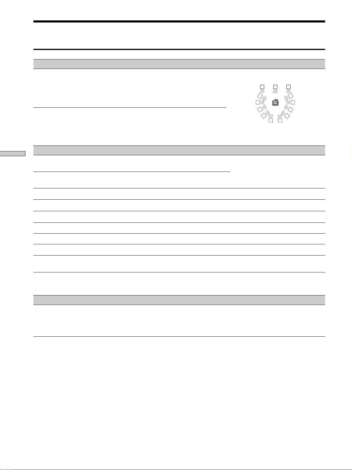
Selecting a Sound Field
Sound field Effect Notes
GENRE : VIRTUAL 3D (continued)
VIRTUAL SEMI-THEATER B
Adds the 3D sound imaging of VIRTUAL SEMI-MULTI
DIMENSION to CINEMA STUDIO B. Reproduces the
sound characteristics of the “Kim Novak Theater” and
creates 5 sets of virtual speakers surrounding the
listener at a 30° angle of elevation from the sound of the
front speakers without using actual rear speakers.
LCR
RSLS
VIRTUAL SEMI-THEATER C
GENRE : MUSIC ETC.
Enjoying Surround Sound
SMALL HALL
LARGE HALL
OPERA HOUSE
JAZZ CLUB
DISCO/CLUB
CHURCH
LIVE HOUSE
ARENA
STADIUM
GAME
Adds the 3D sound imaging of VIRTUAL SEMI-MULTI
DIMENSION to CINEMA STUDIO C. Reproduces the
sound characteristics of the scoring stage and creates 5
sets of virtual speakers surrounding the listener at a 30°
angle of elevation from the sound of the front speakers
without using actual rear speakers.
Reproduces the acoustics of a small rectangular concert
hall.
Reproduces the acoustics of a large rectangular concert
hall.
Reproduces the acoustics of an opera house.
Reproduces the acoustics of a jazz club.
Reproduces the acoustics of a discotheque/dance club.
Reproduces the acoustics of a stone church.
Reproduces the acoustics of a 300-seat live house.
Reproduces the acoustics of a 1000-seat concert hall.
Reproduces the feeling of a large open-air stadium.
Obtains maximum audio impact from video game
software.
LS
RS
RSLS
Ideal for soft acoustic sounds.
Ideal for musicals and opera.
Great for rock or pop music.
Great for sporting events or electric
(amplified) music.
Be sure to set the game machine to stereo
mode when using game software with
stereo sound capabilities.
GENRE : A.F.D.
AUTO FORMAT DECODING You can use this mode as a reference. Set
Note
The effects provided by VIRTUAL THEATER A, B, and C sound fields may cause increased noise in the playback signal.
GB
30
Automatically detects the type of audio signal being
input (Dolby Digital, DTS, Dolby Pro Logic, or standard
2-channel stereo) and performs the proper decoding if
necessary. This mode presents the sound as it was
recorded/encoded, without adding any effects.
the equalizer to OFF while using this mode
to hear the source sound exactly as it was
recorded.
Page 31

Understanding the Multi-Channel Surround Displays
123 45 6 7
OPTICAL COAXIAL
AC-3RFMPEGDTSDUAL
DIGITAL
a
PRO LOGIC
!¡
1 OPTICAL
Lights up when the source signal is a digital signal
being input through the OPTICAL terminal.
2 COAXIAL
Lights up when the source signal is a digital signal
being input through the COAXIAL terminal.
3 a DIGITAL
This indicator lights when the sound field is on and
the unit is decoding signals recorded in the Dolby
Digital (AC-3) format.
4 Playback channel indicators
The letters light to indicate the channels being played
back.
L: Front Left R: Front Right
C: Center (monaural) LS: Left Surround
RS: Right Surround
S: Surround (monaural or the rear components
obtained by Pro Logic processing)
The boxes around the letters light to indicate the
speakers used to playback the channels.
See the next page for details regarding the playback
channel indicators.
5 L.F.E.
The letters “L.F.E.” light up when the disc being
played contains the LFE (Low Frequency Effect)
channel. When the sound of the LFE channel signal is
actually being reproduced, the bars underneath the
letters lights up to indicate the level. Since the LFE
signal is not recorded in all parts of the input signal
the bar indication will fluctuate (and may turn off)
during playback.
L.F.E.LLSCSR
RS
6 S.WOOFER
Lights when sub woofer selection is set to “YES” and
this unit detects that the disc being played does not
contain the LFE channel signal. While this indicator is
lit, this unit creates a sub woofer signal based on the
low frequency components of the front channels.
7 Tuner indicators
These indicators light when using the receiver to tune
in radio stations, etc. See pages 37 to 43 for tuner
operations.
8 D. RANGE
Lights when dynamic range compression is active. See
page 33 and 34 to adjust the dynamic range
compression.
9 PRO LOGIC
Lights when this unit applies Pro Logic processing to
two channel signals in order to output the center and
surround channel signals.
0 DTS
Lights up when DTS signals are input.
Notes
• When playing a DTS format disc, be sure that you have
made digital connections and that INPUT MODE is NOT
set to ANALOG (see 3 on page 23).
• You may hear some noise when starting playback from a
DTS format LD or CD. This, however, is not a malfunction.
!¡ AC-3
Lights when Dolby Digital (AC-3) signals are input.
S.WOOFER STEREO RDS
D.RANGE EQ MONO TA NEWS INFO
MEMORY
890
Enjoying Surround Sound
31
GB
Page 32

Understanding the Multi-Channel Sound Displays
Playback channel display
The display shows which channels are being played back and which speakers are being used. The letters (L, C, R, etc.) light
to show the channels being played back. The boxes around the letters light to show which speakers are being used. The
display varies depending on the number of speakers connected. See the “Speaker Setup and Playback Channel Display”
column in the table below.
This unit also displays the number of channels in the input signal. See the “Input Channel Display” column in the table
below.
Although the table below shows almost all of the configurations available from multi channel surround signals, the ones
marked “
” are the most common.
(Front/Rear)
Enjoying Surround Sound
Recording
Format
1/0
2/0*
3/0
2/1
3/1
2/2
3/2
2/0**
Input Channel Display
DOLBY DIGITAL [1/0]
dts [1/0]
DOLBY DIGITAL [2/0]
dts [2/0]
DOLBY DIGITAL [3/0]
dts [3/0]
DOLBY DIGITAL [2/1]
dts [2/1]
DOLBY DIGITAL [3/1]
dts [3/1]
DOLBY DIGITAL [2/2]
dts [2/2]
DOLBY DIGITAL [3/2]
dts [3/2]
DOLBY DIGITAL [2/0]
dts [2/0]
All speakers
present
DIGITALaC
DTS
DTS
DIGITALaL C R
DTS
DIGITALaLSR
DTS
DIGITALaL CSR
DTS
DIGITALaLLSR
DTS
DTS
PRO LOGIC
DTS
LS
DIGITALaLLSC R
LS
Speaker Setup and Playback Channel Display
Rear speakers
absent
DIGITALaC
C
DTS
L R L R L R L R
R
L
C R
L
L
S
CSR
L
L
C R
L
L CSR
CSR
L
R
RS
R
RS
RS
RS
DTS
DTS
DTS
DTS
DTS
DTS
PRO LOGIC
DTS
L
DIGITALaL C R
L
DIGITALaL
L
DIGITALaL CSR
L
DIGITALaLLSR
L
LS
DIGITALaLLSC R
L
LS
L CSR
L
C
C R
S
S
CSR
C R
CSR
R
R
R
RS
R
RS
RS
RS
Center speaker
absent
DIGITALaC
DTS
DTS
DTS
DTS
DTS
DTS
DTS
PRO LOGIC
DTS
L
DIGITALaL CR
L
DIGITALaLSR
L
DIGITALaL CSR
L
DIGITALaLLSR
L
LS
DIGITALaLLSCR
L
LS
L CSR
L
speakers absent
C
DTS
R
DTS
CR
DTS
R
S
DTS
CSR
DTS
RS
R
RS
DTS
RS
CR
RS
DTS
PRO LOGIC
CSR
DTS
Rear/center
DIGITALaC
C
L
DIGITALaL CR
CR
L
DIGITALaL
DIGITALaL CSR
DIGITALaLLSR
DIGITALaLLSCR
S
L
S
CSR
L
L
LS
CR
L
LS
L CSR
CSR
L
R
R
R
RS
R
RS
RS
RS
DOLBY PRO LOGIC
STEREO PCM**
PRO LOGIC
L CSR
L R L R L R L R
PRO LOGIC
L CSR
* Without Pro Logic
**When Pro Logic is ON or a sound mode from the CINEMA or VIRTUAL 3D genre is selected.
GB
32
PRO LOGIC
L CSR
PRO LOGIC
L CSR
Page 33

Customizing Sound Fields
By adjusting the surround parameters and the
equalization of the front and center speakers, you can
customize the sound fields to suit your particular
listening situation.
Once you customize a sound field, the changes are stored
in memory indefinitely (unless the receiver is unplugged
for about one week). You can change a customized sound
field any time by making new adjustments to the
parameters.
See the table on page 36 for the parameters available in
each sound field.
To get the most from multi channel
surround sound
Position your speakers and do the procedures described
in “Multi-Channel Surround Setup” starting on page 14
before you customize a sound field.
Adjusting the surround parameters
The SURROUND menu contains parameters that let you
customize various aspects of the current sound field. The
settings available in this menu are stored individually for
each sound field.
1 Start playing a program source encoded with multi
channel surround sound.
2 Press CURSOR MODE repeatedly until the
SURROUND indicator lights up.
3 Press the cursor buttons ( or ) to select the
parameter you want to adjust.
4 Press the cursor buttons ( or ) to select setting
you desire. The setting is entered automatically.
EFFECT LEVEL (EFFECT)
Initial setting : (depends on sound mode)
This parameter lets you adjust the “presence” of the
current digital cinema sound surround effect.
WALL TYPE (WALL)
Initial setting : midpoint
When sound is reflected off soft material, such as a
curtain, the high frequency elements are reduced. A hard
wall is highly reflective and does not significantly effect
the frequency response of the reflected sound. This
parameter lets you control the level of the high
frequencies to alter the sonic character of your listening
environment by simulating a softer (S) or harder (H) wall.
The midpoint designates a neutral wall (made of wood).
REVERBERATION (REVERB)
Initial setting : midpoint
Before sound reaches our ears, it is reflected
(reverberated) many times between the left and right
walls, ceiling, and floor. In a large room, sound takes more
time to bounce from one surface to another than in a
smaller room. This parameter lets you control the spacing
of the early reflections to simulate a sonically larger (L) or
smaller (S) room.
• The reverberation can be adjusted ±8 from S (small, –8)
to L (large, +8) in 17 steps.
• The midpoint (0) designates a standard room with no
adjustment.
LFE (Low Frequency Effect) MIX LEVEL (LFE MIX)
Initial setting : 0 dB
This parameter lets you attenuate the level of the LFE
(Low Frequency Effect) channel output from the sub
woofer without effecting the level of the bass frequencies
sent to the sub woofer from the front, center or rear
channels via the Dolby Digital (AC-3) bass redirection
circuitry.
• The level can be adjusted in 1 dB steps from –20 dB to 0
dB (line level). 0 dB outputs the full LFE signal at the
mix level determined by the recording engineer.
• Selecting MUTING mutes the sound of the LFE channel
from the sub woofer. However, the low frequency
sounds of the front, center, or rear speakers are output
from the sub woofer according to the settings made for
each speaker in the speaker setup (page 15).
Enjoying Surround Sound
33
GB
Page 34

Customizing Sound Fields
DYNAMIC RANGE COMPRESSOR (D. RANGE COMP)
Initial setting : OFF
Lets you compress the dynamic range of the sound track.
This may be useful when you want to watch movies at
low volumes late at night.
• OFF reproduces the sound track with no compression.
• STD reproduces the sound track with the dynamic
range intended by the recording engineer.
• 0.1 ~ 0.9 allow you to compress the dynamic range in
small steps to achieve the sound you desire.
• MAX provides a dramatic compression of the dynamic
range.
Note
Dynamic range compression is not possible with DTS sources.
Enjoying Surround Sound
z
This parameter allows you to compress the dynamic range of the
soundtrack based on the dynamic range information included in
the Dolby Digital signal. “STD” is standard compression, but
because many sources have only light compression, you may not
notice much difference when using 0.1~0.9.
Therefore, we recommend using the “MAX” setting. This greatly
compresses the dynamic range and allows you to view movies
late at night at low volumes. Unlike analog limiters, the levels are
predetermined and provide a very natural compression.
REAR BALANCE (REAR)
Initial setting : center
Lets you adjust the balance between the rear left and right
speakers.
• The balance can be adjusted ±8 dB in 1 dB steps.
• This setting can also be adjusted directly using the
supplied remote. See “Adjusting the speaker volume”
(page 18).
About the Dynamic Range Compressor
CENTER LEVEL (CENTER)
Initial setting : 0 dB
Lets you adjust the level of the center speaker.
• The level can be adjusted in 1 dB steps from –10 dB to
+10 dB.
SUB WOOFER LEVEL (WOOFER)
Initial setting : 0 dB
Lets you adjust the level of the sub woofer.
• The level can be adjusted in 1 dB steps from –10 dB to
+10 dB.
Adjusting the equalizer
The EQUALIZER menu lets you adjust the equalization
(low, mid, and high frequencies) of the front and center
speakers. The equalizer settings are stored individually
for each sound field.
1 Start playing a program source encoded with multi
channel surround sound.
2 Press CURSOR MODE repeatedly until the
EQUALIZER indicator lights up.
3 Press the cursor buttons ( or ) to select the
parameter you want to adjust.
4 Press the cursor buttons ( or ) to select setting
you desire. The setting is entered automatically.
z
You can turn off the equalization without erasing it
The equalizer settings are stored separately for each sound field.
Press the EQ ON/OFF button to turn the EQ indicator off.
REAR LEVEL (REAR)
Initial setting : 0 dB
Lets you adjust level of the rear (left and right) speakers.
• The level can be adjusted in 1 dB steps from –10 dB to
+10 dB.
• This setting can also be adjusted directly using the
supplied remote. See “Adjusting the speaker volume”
(page 18).
GB
34
Page 35

Front speaker bass adjustment (Level/Frequency)
1 Use
2 Use
Repeat until you achieve the sound you desire.
Level
(dB)
• The level can be adjusted ±10 dB in 1 dB steps.
• The frequency can be adjusted from 100 Hz to 1.0 kHz
in 21 steps.
Front speaker midrange adjustment (Level/
Frequency)
Adjust as described in “Front speaker bass adjustment”.
• The level can be adjusted ±10 dB in 1 dB steps.
• The frequency can be adjusted from 500 Hz to 5.0 kHz
in 21 steps.
Front speaker treble adjustment (Level/
Frequency)
Adjust as described in “Front speaker bass adjustment”.
• The level can be adjusted ±10 dB in 1 dB steps.
• The frequency can be adjusted from 1.0 kHz to 10 kHz
in 21 steps.
/ to select the level (dB) or frequency (Hz).
/ to adjust.
BASS
Frequency
(Hz)
Frequency
(Hz)
Frequency
TREBLEMID
(Hz)
Rear speaker bass adjustment (Level/Frequency)
Adjust as described in “Front speaker bass adjustment”.
• The level can be adjusted ±10 dB in 1 dB steps.
• The frequency can be adjusted from 100 Hz to 1.0 kHz
in 21 steps.
Rear speaker midrange adjustment (Level/
Frequency)
Adjust as described in “Front speaker bass adjustment”.
• The level can be adjusted ±10 dB in 1 dB steps.
• The frequency can be adjusted from 500 Hz to 5.0 kHz
in 21 steps.
Rear speaker treble adjustment (Level/Frequency)
Adjust as described in “Front speaker bass adjustment”.
• The level can be adjusted ±10 dB in 1 dB steps.
• The frequency can be adjusted from 1.0 kHz to 10 kHz
in 21 steps.
Resetting customized sound fields to the
factory settings
1 If the power is on, press 1/u to turn off the power.
2 Hold down SOUND FIELD ON/OFF and press 1/u.
“SURR CLEAR!” appears in the display and all sound
fields are reset at once.
Enjoying Surround Sound
Center speaker bass adjustment (Level/
Frequency)
Adjust as described in “Front speaker bass adjustment”.
• The level can be adjusted ±10 dB in 1 dB steps.
• The frequency can be adjusted from 100 Hz to 1.0 kHz
in 21 steps.
Center speaker midrange adjustment (Level/
Frequency)
Adjust as described in “Front speaker bass adjustment”.
• The level can be adjusted ±10 dB in 1 dB steps.
• The frequency can be adjusted from 500 Hz to 5.0 kHz
in 21 steps.
Center speaker treble adjustment (Level/
Frequency)
Adjust as described in “Front speaker bass adjustment”.
• The level can be adjusted ±10 dB in 1 dB steps.
• The frequency can be adjusted from 1.0 kHz to 10 kHz
in 21 steps.
35
GB
Page 36

Customizing Sound Fields
Adjustable parameters for each sound field
Sound EFFECT WALL REVERB LFE D.RANGE REAR REAR CENTER WOOFER
field GENRE MODE LEVEL TYPE TIME MIX COMP BAL. LEVEL LEVEL LEVEL EQ
Off — — rr r
On CINEMA NORMAL SURROUND rr rrr rr
Enjoying Surround Sound
CINEMA STUDIO A rrrrrrrr
CINEMA STUDIO B rrrrrrrr
CINEMA STUDIO C rrrrrrrr
NIGHT THEATER rr rr r rr r rr
MONO MOVIE rr rr r rr r rr
STEREO MOVIE rr rr r rr r rr
VIRTUAL 3D V. MULTI REAR rrrrrrrr
V. MULTI DIMENSION rrrrrrrr
V. THEATER A rrrrrrrr
V. THEATER B rrrrrrrr
V. THEATER C rrrrrrrr
V. ENHANCED A rrr rrr
V. ENHANCED B rrr rrr
V. SEMI-M.DIMENSION rrr rrr
V. SEMI-THEATER A rrr rrr
V. SEMI-THEATER B rrr rrr
V. SEMI-THEATER C rrr rrr
MUSIC etc. SMALL HALL rr rr r rr r rr
LARGE HALL rr rr r rr r rr
OPERA HOUSE rr rr r rr r rr
JAZZ CLUB rr rr r rr r rr
DISCO/CLUB rr rr r rr r rr
CHURCH rrrr r rr r rr
LIVE HOUSE rr rr r rr r rr
ARENA rr rr r rr r rr
STADIUM rr rr r rr r rr
GAME rrrr r rr r rr
A.F.D. AUTO FORMAT DECODE rr rrr rr
36
GB
Page 37

Receiving Broadcasts
You can tune in stations on this receiver in the following
ways:
Automatic FM Memory (AUTOBETICAL)
You can have the receiver automatically store up to 30 of
the clearest FM and FM RDS stations in alphabetical
order. (see page 38).
This chapter describes how to receive
FM or AM broadcasts and how to
preset selected stations.
Direct Tuning
You can enter a frequency of the station you want directly
by using the numeric buttons on the supplied remote (see
page 39).
Automatic Tuning
If you don’t know the frequency of the station you want,
you can let the receiver scan all available stations in your
area (see page 39).
Preset Tuning
After you have tuned in stations using Direct Tuning or
Automatic Tuning, you can preset them to the receiver
(see page 40). Then you can tune in any of the stations
directly by entering its 2-character code (see page 40). Up
to 30 FM or AM stations can be preset. The receiver will
also scan all the stations that you have preset (see page
40).
RDS functions
This receiver also allows you to use RDS (Radio Data
System), which enables radio stations to send additional
information along with the regular program signal. You
can use the following three convenient RDS features:
— Displaying RDS information (see page 41)
— Scanning preset stations by program type (see page
41)
— Using the EON function (see page 41)
Receiving Broadcasts
Note that RDS is operable only for FM stations.
Not all FM stations provide RDS service, nor do they provide the
*
same types of services. If you are not familiar with the RDS services
in your area, check with your local radio stations for details.
Before you begin, make sure you have:
• Connected an FM and AM antenna to the receiver (see
page 5).
• Selected the appropriate speaker system (see page 23).
*
37
GB
Page 38

PRESET TUNING +/–
DISPLAY
MEMORY
TUNING/PTY SELECT +/–
Storing FM Stations Automatically (AUTOBETICAL)
Receiving Broadcasts
MASTER VOLUME
5
•
•
•
•
•
•
46
MULTI CHANNEL DECODING
VIDEO 1
VIDEO 2 VIDEO 3 DVD TV/LD TAPE MD/DAT CD TUNER PHONO
g
DISPLAY
SPEAKERS
A
B
OFF
A
+
B
PRESET TUNING
– +
PHONES
SHIFT FM/AM
MEMORY FM MODE
VIDEO 3 INPUT
– PTY SELECT
TUNING/
+
RLVIDEOS-VIDEO AUDIO
PTY EON– RDS –
SURROUND
ON/OFF
EQUALIZER
INDEX
CURSOR
SET UP
MODE
GENRE MODE ON/OFF
SOUND FIELD
EQ
BASS BOOST
EQ
5.1
INPUT
INPUT
MODE
BALANCE
•
SOUND FIELD
•
•
LR
•
•
•
•
3
•
•
•
2
•
•
•
1
•
•
•
•
0
10
FUNCTION
MODE MUTING
•
•
7
•
9
•
•
•
•
8
•
•
•
SHIFT
FM/AM
FUNCTIONFM MODE
PTY
EON
Brief descriptions of buttons and controls
used to receive broadcasts
PRESET TUNING +/– buttons: Press to scan all preset
radio stations.
DISPLAY button: Press to display the RDS information.
MEMORY button: Uses for memorizing preset stations.
TUNING/PTY SELECT +/– buttons: Press to scan all
available radio stations or select program types.
FUNCTION control: Rotate to select the tuner.
EON button: Press to set the receiver to switch stations
automatically.
PTY button: Press to scan preset stations by the program
type.
FM MODE button: If “STEREO” flashes in the display
and the FM stereo reception is poor, press this button to
improve the sound. You will not be able to enjoy stereo
effect but the sound will be less distorted.
This function lets you store up to 30 FM and FM RDS
stations in alphabetical order without redundancy.
Additionally, it only stores the stations with the clearest
signals.
If you want to store FM or AM stations one by one, see
“Presetting radio stations” on page 40.
For details on the buttons used in this section, see “Brief
descriptions of buttons and controls used to receive
broadcasts” on this page.
1 Press 1/u to turn off the receiver.
2 Hold down MEMORY and press 1/u to turn the
receiver back on.
“Autobetical select” appears in the display and the
receiver scans and stores all the FM and FM RDS
stations in the broadcast area.
For RDS stations, the tuner first checks for stations
broadcasting the same program, then stores only the
one with the clearest signal. The selected RDS stations
are sorted alphabetically by their Program Service
name, then assigned a two character preset code. For
more details on RDS see page 41.
Regular FM stations are assigned two character preset
codes and stored after the RDS station.
When done, “Autobetical finish” appears in the
display momentarily and the receiver returns to
normal operation.
Notes
• Do not press any of the buttons on the receiver or supplied
remote during autobetical operation.
• If you move to another area, repeat this procedure to store
stations in your new area.
• For details on tuning the stored stations, see page 40.
• The FM MODE setting is also stored along with the station.
• If you move the antenna after storing stations with this
procedure, the stored settings may no longer be valid. If this
happens, repeat this procedure to store the stations again.
Note
If “STEREO” does not appear at all even when the FM broadcast
is received normally, press this button to turn on the “STEREO”
indication.
FM/AM button: Press to select the FM or AM band.
SHIFT button: Press to select a memory page (A, B, or C)
for presetting radio stations or tuning to preset stations.
GB
38
Page 39

Direct Tuning
Automatic Tuning
Use the supplied remote to perform the
following operations
For details on the buttons used in this section, see the
operating instructions for the supplied remote.
1 Rotate FUNCTION to select the tuner.
The last received station is tuned in.
2 Press FM/AM to select the FM or AM band.
3 Press DIRECT (or D.TUNING).
4 Press the numeric buttons to enter the frequency.
Example 1: FM 102.50 MHz
bbbb
10250
Example 2: AM 1350 kHz
(You don’t have to enter the last “0”.)
bbb
1350
If you cannot tune in a station and the
entered numbers flash
Make sure you’ve entered the right frequency. If not,
repeat Steps 3 and 4.
If the entered numbers still flash, the frequency is not
used in your area.
For details on the buttons used in this section, see “Brief
descriptions of buttons and controls used to receive
broadcasts” on page 38.
1 Rotate FUNCTION to select the tuner.
The last received station is tuned in.
2 Press FM/AM to select the FM or AM band.
3 Press TUNING (PTY SELECT) + or TUNING (PTY
SELECT) –.
Press the + button to scan from low to high; press the –
button to scan from high to low.
When the receiver reaches either end of the
band
Scanning is repeated in the same direction.
The receiver stops scanning whenever a station is
received.
Receiving Broadcasts
4 To continue scanning, press TUNING (PTY SELECT) +
or TUNING (PTY SELECT) – again.
5 If you’ve tuned in an AM station, adjust the
direction of the AM loop antenna for optimum
reception.
6 Repeat Steps 2 to 5 to receive another station.
z
If you try to enter a frequency that is too precise for the
tuning scale
The entered value is automatically rounded up or down.
Tuning scale for direct tuning is:
FM: 50 kHz
AM: 9 kHz
39
GB
Page 40

Preset Tuning
Receiving Broadcasts
For details on the buttons used in this section, see “Brief
descriptions of buttons and controls used to receive
broadcasts” on page 38.
Before tuning to preset stations, be sure to preset them by
performing steps on “Presetting radio stations” below.
Presetting radio stations
1 Rotate FUNCTION to select the tuner.
The last received station is tuned in.
2 Tune in the station that you want to preset using
Direct Tuning (page 39)‚ or Automatic Tuning (page
39).
3 Press MEMORY.
“MEMORY” appears in the display for a few seconds.
Do Steps 4 to 6 before “MEMORY” goes out.
4 Press SHIFT to select a memory page (A, B or C).
Each time you press SHIFT, the letter “A”, “B” or “C”
appears in the display.
5 Press PRESET TUNING + or PRESET TUNING – to
select a number.
If “MEMORY” goes out before you press the preset
number, start again from Step 3.
Tuning to preset stations
You can tune the preset stations either of the following
two ways.
Scanning the preset stations
1 Rotate FUNCTION to select the tuner.
The last received station is tuned in.
2 Press PRESET TUNING + or PRESET TUNING –
repeatedly to select the preset station you want.
Each time you press the button, the receiver tunes in
one preset station at a time, in the corresponding order
and direction as follows:
nA1˜A2˜...˜A0˜B1˜B2˜...˜B0N
nC0˜...C2˜C1N
z You can scan the preset stations by program type
See page 41.
Using the preset codes
Use the supplied remote control for the following
operations.
1 Select the tuner.
The last received station is tuned in.
6 Press MEMORY again to store the station.
If “MEMORY” goes out before you press the preset
number, start again from Step 3.
7 Repeat Steps 2 to 6 to preset another station.
To change a preset number to another station
Do Steps 1 to 6 to preset the new station to the number.
Note
If the AC power cord is disconnected for about one week, all the
preset stations will be cleared from the receiver’s memory, and
you will have to preset the stations again.
2 Press SHIFT to select a memory page (A, B or C),
then press the preset number of the station you
want.
40
GB
Page 41

Using the Radio Data System (RDS)
Receiving RDS broadcasts
Simply select a station on the FM band using direct
tuning (page 39), automatic tuning (page 39), or
preset tuning (page 40).
When you tune in a station that provides RDS services,
the RDS indicator lights up and the program station name
appears in the display.
Note
RDS may not work properly if the station you tuned to is not
transmitting the RDS signal properly or if the signal strength is
weak.
Displaying RDS information
While receiving an RDS station, press DISPLAY
repeatedly to change the RDS information on the
display window as follows:
v
PS (Program Station name)
v
Frequency
v
PTY (Program TYpe) indication
v
RT (Radio Text) indication
v
CT (Current Time) indication (in 24-hour system)
v
Sound field currently applied
a)
a)
b)
c)
Scanning preset stations by program type
You can tune in preset stations according to a program
type that you specify. The receiver scans for stations in its
preset memory currently broadcasting the specified
program type.
1 Press PTY.
2 Press (TUNING) PTY SELECT + or (TUNING) PTY
SELECT – to select the program type.
See the table on the next page for information on each
program type.
3 Press PTY.
While the receiver is scanning stations, “PTY
SEARCH” and the program type indication appear
alternately in the display window.
When the receiver finds a station, the receiver stops
scanning.
When the receiver could not find any preset stations
currently broadcasting the specified program type,
“PTY not found” appears in the display.
Using the EON function
The EON (Enhanced Other Network) function allows the
receiver to switch automatically to a station broadcasting
traffic announcements, news, or information programs.
When such a program starts on a station networking with
the preset FM RDS station, the receiver automatically
tunes in the station.
After the program ends, the receiver switches back to the
original preset station or the program source you were
originally listening to.
Receiving Broadcasts
a) This information also appears for non-RDS FM stations.
b) Type of program being broadcast (See page 42.)
c) Text messages sent by the RDS station
Notes
• If there is an emergency announcement by government
authorities, “Alarm-Alarm!” flashes in the display.
• If a station does not provide a particular RDS service, “No XX”
(such as “No Clock Time”) appears in the display.
• When a station broadcasts radio text data, it is displayed at the
same rate at which it is sent from the station. Any change in
this rate is reflected in the display rate of the data.
41
GB
Page 42

Using the Radio Data System (RDS)
Receiving Broadcasts
1 Tune in a preset FM RDS station so that the RDS
indicator lights up.
2 Press EON repeatedly to select the type of the
program to be tuned in.
Each time you press the EON button, the indication
for the type of the program lights up alternately as
shown below.
v
TA (Traffic Announcement)
v
NEWS (News)
v
INFO (Information program)
v
OFF (No indication lights up.)
After selecting the type of the program, you can select
any other component.
When the receiver automatically tunes in the program,
the indication that you’ve selected in Step 2 flashes in
the display.
To stop listening to the program
Press EON during program reception. The indication that
you’ve selected in Step 2 lights up and the receiver
switches back to the program source or the station you
were listening to.
To turn off the EON function
Press EON repeatedly in Step 2 above so that no program
type indication lights up in the display.
Notes
• After selecting the type of the program, if you tune in an AM
station, the program type indicator turns off and the receiver
will no longer tune in the program.
• Be sure to turn off the EON function when you want to record a
program without interruptions, especially when doing timeractivated recording.
• “Weak Signal” appears in the display when the signal of the
program is weak.
Description of program types
Program type indication Description
News News programs
Current Affairs Topical programs that expand on
current news
Information Programs offering information
on a wide spectrum of subjects,
including consumer affairs and
medical advice
Sport Sports programs
Education Educational programs, such as
“how-to” and advice programs
Drama Radio plays and serials
Cultures Programs about national or
regional culture, such as
language and social concerns
Science Programs about the natural
sciences and technology
Varied Speech Other types of programs such as
celebrity interviews, panel
games, and comedy
Pop Music Popular music programs
Rock Music Rock music programs
M.o.R. Music Easy Listening
Light Classics M Instrumental, vocal, and choral
music
Serious Classics Performances of major
orchestras, chamber music,
opera, etc.
Other Music Music that does not fit into any
categories above, such as
Rhythm & Blues and Reggae
42
GB
Page 43

Program type indication Description
Weather & Metr Weather information
Finance Stock market reports and trading,
etc.
Children’s Progs Programs for children
Social Affairs Programs about people and the
things that affect them
Religion Programs of religious content
Phone In Programs where members of the
public express their views by
phone or in a public forum
Travel & Touring Programs about travel. Not for
announcements that are located
by TP/TA.
Leisure & Hobby Programs on recreational
activities such as gardening,
fishing, cooking, etc.
Jazz Music Jazz programs
Country Music Country music programs
National Music Programs featuring the popular
music of the country or region
Oldies Music Programs featuring oldies music
Folk Music Folk music programs
Documentary Investigative features
None Any programs not defined above
Receiving Broadcasts
43
GB
Page 44

Other Operations
Cursor buttons
MASTER VOLUME
5
•
•
•
•
•
•
46
MULTI CHANNEL DECODING
VIDEO 1
VIDEO 2 VIDEO 3 DVD TV/LD TAPE MD/DAT CD TUNER PHONO
g
DISPLAY
SPEAKERS
A
B
OFF
+
B
A
PRESET TUNING
– +
PHONES
SHIFT FM/AM
MEMORY FM MODE
VIDEO 3 INPUT
– PTY SELECT
TUNING/
+
RLVIDEOS-VIDEO AUDIO
PTY EON– RDS –
SURROUND
ON/OFF
EQUALIZER
INDEX
CURSOR
SET UP
MODE
EQ
5.1
INPUT
SOUND FIELD
GENRE MODE ON/OFF
SOUND FIELD
EQ
BASS BOOST
INPUT
MODE
BALANCE
•
•
•
LR
•
•
•
•
•
3
•
•
•
2
•
•
•
1
•
•
•
•
0
10
FUNCTION
MODE MUTING
•
7
•
•
•
8
•
•
•
9
•
•
CURSOR MODE
SET UP
FUNCTION
Brief descriptions of buttons and controls
that appear in this chapter
CURSOR MODE button: Press repeatedly to light up the
INDEX indicator to index preset stations or program
sources.
Cursor buttons (
/ / / ): After pressing the SET
UP button or CURSOR MODE button, use these buttons
to make the actual setting.
SET UP button: Press repeatedly to display “OTHER”.
FUNCTION control: Rotate to select the tuner or other
source.
44
GB
Page 45

Indexing Preset Stations and Program Sources
You can enter a name of up to 8 characters for preset
stations (station index) and program sources. These index
names (for example, “VHS”) appear in the receiver’s
display when a station or program source is selected.
Note that no more than one name can be entered for each
preset station or program source.
This function is useful for distinguishing components of
the same kind. For example, two VCRs can be specified
as “VHS” and “8MM,” respectively. It is also handy for
identifying components connected to jacks meant for
another type of component, for example, a second CD
player connected to the MD/DAT jacks.
1 To index a preset station
Rotate FUNCTION to select the tuner.
The last station you received is tuned in.
To index a program source
Select the program source (component) to be
named, then go to Step 3.
2 Tune in the preset station you want to create an
index name for.
If you are not familiar with how to tune in preset
stations, see “Tuning to preset stations” on page 40.
3 Press CURSOR MODE repeatedly until the INDEX
indicator lights up.
4 Create an index name by using the cursor buttons
as follows:
Press
move the cursor to the next position.
The index name is stored automatically.
or to select a character, then press to
Recording
Your receiver makes it easy to record to and from the
components connected to it. You don’t have to connect
the playback and recording components directly to each
other: once you select a program source on the receiver,
you can record and edit as you normally would using the
controls on each component.
Before you begin, make sure you’ve connected all
components properly.
FUNCTION
MASTER VOLUME
5
•
•
•
•
•
•
46
MULTI CHANNEL DECODING
VIDEO 1
VIDEO 2 VIDEO 3 DVD TV/LD TAPE MD/DAT CD TUNER PHONO
g
DISPLAY
SPEAKERS
A
B
OFF
A
+B
PRESET TUNING
– +
PHONES
SHIFT FM/AM
MEMORY FM MODE
VIDEO 3 INPUT
– PTY SELECT
TUNING/
+
RLVIDEOS-VIDEO AUDIO
PTY EON– RDS –
SURROUND
EQUALIZER
INDEX
CURSOR
SET UP
MODE
EQ
5.1
ON/OFF
INPUT
SOUND FIELD
GENRE MODE ON/OFF
SOUND FIELD
EQ
BASS BOOST
INPUT
MODE
BALANCE
•
•
•
LR
ç
c
ç
Playback component
(program source)
Recording component
(tape deck, MD deck,
VCR)
ç: Audio signal flow
c: Video signal flow
Recording on an audio tape or MiniDisc
You can record on a cassette tape or MiniDisc using the
receiver. See the instruction manual of your cassette deck
or MD deck if you need help.
1 Select the component to be recorded.
2 Prepare the component for playing.
For example, insert a CD into the CD player.
•
•
•
•
3
•
•
•
2
•
•
•
1
•
•
•
•
0
10
FUNCTION
MODE MUTING
c
•
•
7
9
•
•
•
•
•
8
•
•
•
Other Operations
To insert a space
Press
or until a blank space appears in the
display (the space character is between “11” and “A”).
If you’ve made a mistake
Press
or repeatedly until the character to be
changed flashes, then select the right character.
To assign index names to other stations
Repeat Steps 2 to 4.
3 Insert a blank tape or MD into the recording deck
and adjust the recording level, if necessary.
4 Start recording on the recording deck, then start
playback on the playback component.
Notes
• You cannot record the audio signals from a component
connected to the 5.1 INPUT jacks.
• You cannot record a digital audio signal using a component
connected to the analog TAPE REC OUT or MD/DAT REC
OUT jacks. To record a digital audio signal, connect a digital
component to the DIGITAL MD/DAT OUT jacks.
• Sound adjustments do not affect the signal output from the
TAPE REC OUT or MD/DAT REC OUT jacks.
45
GB
Page 46

Recording
Adjustments Using the SET UP Button
Recording on a video tape
You can record from a VCR, a TV, or an LD player using
the receiver. You can also add audio from a variety of
audio sources when editing a video tape. See your VCR
or LD player’s instruction manual if you need help.
1 Select the program source to be recorded.
2 Prepare the component for playing.
For example, insert the laser disc you want to record
into the LD player.
3 Insert a blank video tape into the VCR (VIDEO 1 or
VIDEO 2) for recording.
4 Start recording on the recording VCR, then start
playing the video tape or laser disc you want to
record.
z
You can record the sound from any audio source onto a
video tape while copying from a video tape or laser disc
After locating the point where you want to start recording from
another audio source, select the program source, then start
playback. The audio from that source will be recorded onto the
Other Operations
audio track of the video tape instead of the audio from the
original medium.
The SET UP button allows you to make following
adjustments.
Adjusting the brightness of the display
1 Press SET UP repeatedly until “OTHER” appears in
the display.
2 Press the cursor buttons ( or ) to select
“DIMMER”.
3 Press the cursor buttons ( or ) to select the
brightness level.
You can select any of four brightness levels.
For example, if you want to record video from the component
connected to the VIDEO 1 jacks and audio from the component
connected to the CD jacks:
1 Rotate FUNCTION to select VIDEO 1.
2 Press MODE repeatedly to display “A:XXX”
3 Rotate FUNCTION to display “A: CD.”
See “MODE button” on page 22 for details on use of the MODE
button.
To resume audio recording from the original medium, perform
the procedure above to select the video source again.
Notes
• You cannot record the audio signals from a component
connected to the 5.1 INPUT jacks.
• You cannot record a digital audio signal using a component
connected to the analog TAPE REC OUT or MD/DAT REC
OUT jacks. To record a digital audio signal, connect a digital
component to the DIGITAL MD/DAT OUT jacks.
• You cannot, however, record multi channel surround digital
signals from a DVD, etc.
46
GB
Page 47

Additional
Troubleshooting
Information
If you experience any of the following difficulties while
using the receiver, use this troubleshooting guide to help
you remedy the problem. Also, see “Checking the
connections” on page 19 to verify that the connections are
correct. Should any problem persist, consult your nearest
Sony dealer.
There’s no sound or only a very low-level sound
is heard.
/ Check that the speakers and components are
connected securely.
/ Make sure that you’ve selected the correct
component on the receiver.
/ Make sure that you’ve set the SPEAKERS selector
correctly (see page 23).
/ Press MUTING on the remote if “MUTING”
appears in the display.
/ The protective device on the receiver has been
activated because of a short circuit. Turn off the
receiver, eliminate the short-circuit problem and
turn on the power again.
The left and right sounds are unbalanced or
reversed.
/ Check that the speakers and components are
connected correctly and securely.
/ Adjust the BALANCE control.
Severe hum or noise is heard.
/ Check that the speakers and components are
connected securely.
/ Check that the connecting cords are away from a
transformer or motor, and at least 10 feet (3 meters)
away from a TV set or fluorescent light.
/ Move your TV away from the audio components.
/ Make sure you’ve grounded SIGNAL GND y
terminal.
/ The plugs and jacks are dirty. Wipe them with a
cloth slightly moistened with alcohol.
No sound is heard from the center speaker.
/ Make sure the sound field function is on (press
SOUND FIELD ON/OFF).
/ Select a sound field from the CINEMA or
VIRTUAL 3D genre (except MONO MOVIE and
STEREO MOVIE) (see page 28).
/ Adjust the speaker volume (see page 18).
/ Make sure the center speaker size parameter is set
to either SMALL or LARGE (see page 15).
Additional Information
47
GB
Page 48

Troubleshooting
No sound or only a very low-level sound is heard
from the rear speakers.
/ Make sure the sound field function is on (press
SOUND FIELD ON/OFF).
/ Select a sound field from the CINEMA or
VIRTUAL 3D genres (except MONO MOVIE and
STEREO MOVIE) (see page 28).
/ Adjust the speaker volume (see page 18).
/ Make sure the rear speaker size parameter is set to
either SMALL or LARGE (see page 15).
Recording cannot be done.
/ Check that the components are connected correctly.
/ Select the source component by rotating the
FUNCTION control.
/ You cannot record the audio signals from a
component connected to the 5.1 INPUT jacks.
/ When recording from a digital component, make
sure the input mode is set to ANALOG (see page
23) before recording with a component connected
to the analog MD/DAT or TAPE terminals.
/ When recording from a digital component, make
sure the input mode is set to DIGITAL (see page
23) before recording with the component
connected to the DIGITAL MD/DAT OUT
terminals.
Radio stations cannot be tuned in.
/ Check that the antennas are connected securely.
Additional Information
Adjust the antennas and connect an external
antenna if necessary.
/ The signal strength of the stations is too weak
(when tuning in with automatic tuning). Use
direct tuning.
/ No stations have been preset or the preset stations
have been cleared (when tuning by scanning preset
stations). Preset the stations (see page 40).
/ Press DISPLAY so that the frequency appears in
the display.
RDS does not work.
/ Make sure that you’re tuned to an FM RDS station.
/ Select a stronger FM station.
The station was interrupted by another station
or the receiver automatically starts scanning
stations.
/ The EON function is activated. Turn off the EON
function if you don’t want the current program to
be interrupted.
The RDS information that you want does not
appear.
/ Contact the radio station and find out whether or
not they actually provide the service in question.
If so, the service may be temporarily out of order.
The surround effect cannot be obtained.
/ Make sure the sound field function is on (press
SOUND FIELD ON/OFF).
/ Make sure that the SPEAKERS selector is set to A
or B (not A+B) if you connected two sets of front
speakers.
/ The sound field effects do not function when the
5.1 INPUT is selected.
No picture or an unclear picture appears on the
TV screen or monitor.
/ Select the appropriate function on the receiver.
/ Set your TV to the appropriate input mode.
/ Move your TV away from the audio components.
The video image on the TV screen or monitor
does not correspond to the selected component.
/ Check the source of the video signal by pressing
MODE repeatedly to display “V:XXX”. Then rotate
FUNCTION to select the appropriate video source
(if necessary).
The remote does not function.
/ Point the remote at the remote sensor g on the
receiver.
/ Remove any obstacles in the path between the
remote and the receiver.
/ Replace all batteries in the remote with new ones,
if they are weak.
/ Make sure you select the correct function on the
remote.
/ If the remote is set to operate the TV only, use the
remote to select a source or component other than
TV before operating the receiver or other
component.
Reference sections for clearing the
receiver’s memory
To clear See
All memorized settings Page 19
Customized sound fields page 35
48
GB
Page 49

Specifications
Amplifier section
POWER OUTPUT
Stereo mode (4 ohms DIN 1 kHz)
100 W + 100 W
Surround mode
(4 ohms DIN 1 kHz)
Front: 100 W + 100 W
a)
Center
Rear
a) Depending on the sound field settings and
the source, there may be no sound output.
Frequency response
PHONO:
CD, TAPE, MD/DAT,
Inputs (Analog)
PHONO:
CD, DVD, TAPE, MD/
b) 78’ IHF
c) Weighted network, input level
: 100W
a)
: 100 W + 100 W
RIAA equalization
curve
±0.5 dB
DVD, TV/LD,
VIDEO 1, 2, and
VIDEO 3:
10 Hz - 50 kHz
+0.5/–2 dB (with
sound field, tone,
and bass booster
bypassed)
Sensitivity: 2.5 mV
Impedance:
50 kilohms
b)
S/N
: 75 dB (A,
c)
2.5 mV
)
DAT, TV/LD,
VIDEO 1, 2, 3, and
5.1 INPUT:
Sensitivity: 150 mV
Impedance:
50 kilohms
b)
S/N
: 82 dB (A,
150 mV
c)
)
Inputs (Digital)
DVD (coaxial):
Sensitivity: –
Impedance: 75 ohms
S/N: 100 dB (A,
20 kHz LPF)
DVD, TV/LD, MD/
DAT (Optical):
Sensitivity: –
Impedance: –
S/N: 100 dB (A,
20 kHz LPF)
Outputs TAPE, MD/DAT (REC
OUT); VIDEO 1, 2
(AUDIO OUT):
Voltage: 150 mV,
Impedance:
10 kilohms
WOOFER:
Voltage: 2 V
Impedance:
1 kilohms
PHONES:
Accepts low- and
high-impedance
headphones
BASS BOOST +6 dB at 70 Hz
Sampling Frequency
48 kHz
EQ BASS:
100 Hz~1.0kHz
(21 steps)
MID:
500 Hz~5.0kHz
(21 steps)
TREBLE:
1.0 kHz~10kHz
(21 steps)
Gain levels:
±10 dB, 1 dB step
FM tuner section
Tuning range 87.5 - 108.0 MHz
Antenna terminals
75 ohms, unbalanced
Sensitivity Mono: 18.3 dBf,
2.2 µV/75 ohms
Stereo: 38.3 dBf,
22.5 µV/75 ohms
Usable sensitivity
11.2 dBf,
1 µV/75 ohms (IHF)
S/N Mono: 76 dB
Stereo: 70 dB
Harmonic distortion at 1 kHz
Mono: 0.3%
Stereo: 0.5%
Separation 45 dB at 1 kHz
Frequency response
30 Hz - 15 kHz
+0.5/–2 dB
Selectivity 60 dB at 400 kHz
Additional Information
AM tuner section
Tuning range 531 - 1,602 kHz
(with 9-kHz tuning
scale)
Antenna Loop antenna
Usable sensitivity
50 dB/m (at 999 kHz)
S/N 54 dB (at 50 mV/m)
Harmonic distortion
0.5 % (50 mV/m,
400 kHz)
Selectivity 35 dB
49
GB
Page 50

Specifications
Video section
Inputs 1 Vp-p 75 ohms
Outputs 1 Vp-p 75 ohms
General
System Tuner section:
PLL quartz-locked
digital synthesizer
system
Preamplifier section:
Low-noise NF type
equalizer
Power amplifier
section:
Pure-complementary
SEPP
Power requirements
230 V AC, 50/60 Hz
Power consumption
270 W
AC outlets 1 switched maximum
Additional Information
Dimensions 430 × 160 × 410 mm
Mass (Approx.)
13 kg
Supplied accessories See page 4.
Design and specifications are subject
to change without notice.
100 W
including projecting
parts and controls
50
GB
Page 51

Glossary
Surround sound
Sound that consists of three elements:
direct sound, early reflected sound
(early reflections) and reverberative
sound (reverberation). The acoustics
of the surrounding space affect the
way these three sound elements are
heard. Surround sound combines
these sound elements in such a way
that you actually can sense the size of
the venue, as well as its type.
• Types of sound
Early reflections
Direct sound
• Transition of sound from rear speakers
Direct sound
Level
Early reflection time
Early
reflections
Reverberation
Reverberation
Time
Dolby Digital (AC-3)
This sound format for movie theaters
is more advanced than Dolby Pro
Logic Surround. In this format, the
rear speakers output stereo sound
with an expanded frequency range
and a subwoofer channel for deep
bass is independently provided. This
format is also called “5.1” because the
subwoofer channel is counted as 0.1
channel (since it functions only when
a deep bass effect is needed). All six
channels in this format are recorded
separately to realize superior channel
separation. Furthermore, since all the
signals are processed digitally, less
signal degradation occurs. The name
“AC-3” comes from the fact that it is
the third audio coding method to be
developed by the Dolby Laboratories
Licensing Corporation.
Digital Cinema Sound
This is the generic name of the
surround sound produced by digital
signal processing technology
developed by Sony. Unlike previous
surround sound fields mainly
directed at the reproduction of music,
Digital Cinema Sound is designed
specifically for the enjoyment of
movies.
Additional Information
Dolby Pro Logic Surround
As one method of decoding Dolby
Surround, Dolby Pro Logic Surround
produces four channels from twochannel sound. Compared with the
former Dolby Surround system,
Dolby Pro Logic Surround reproduces
left-to-right panning more naturally
and localizes sounds more precisely.
To take full advantage of Dolby Pro
Logic Surround, you should have one
pair of rear speakers and a center
speaker. The rear speakers output
monaural sound.
5.1 INPUT jacks
These jacks are used to input decoded
Dolby Digital (AC-3) audio signals,
allowing you to enjoy 5.1 channel
surround sound. Use these jacks to
connect a Dolby Digital (AC-3)
decoder or a DVD player with a builtin AC-3 decoder.
Note
This receiver incorporates a multi channel
surround decoder. Therefore it is not
necessary to connect a separate Dolby
Digital (AC-3) decoder to enjoy multi
channel surround.
51
GB
Page 52

Tables of Settings Using the CURSOR MODE and SET UP buttons
You can make various settings using the CURSOR MODE, SET UP, and cursor buttons. The tables below show each of the
settings that these buttons can make.
Press CURSOR MODE repeatedly
to light up
SURROUND indicator
EQUALIZER indicator
Additional Information
Press or to select Then or to select See page
EFFECT LEVEL depends on sound mode (in 21 steps)
WALL TYPE between –8 to +8 (in 1 increment steps)
REVERBERATION TIME –8 to +8 (in 1 increment steps)
LFE MIX LEVEL MUTING, or –20 dB to 0 dB (in 1 dB steps)
DYNAMIC RANGE COMP Off, 0.1 to 0.9 (in 0.1 dB steps), STD, or MAX
REAR BALANCE between –8 to +8 (in 1 increment steps)
REAR LEVEL between –10 dB to +10 dB (in 1 dB steps)
CENTER LEVEL between –10 dB to +10 dB (in 1 dB steps)
SUB WOOFER LEVEL between –10 dB to +10 dB (in 1 dB steps)
FRONT BASS GAIN between –10 dB to +10 dB (in 1 dB steps) 34
FRONT BASS FREQUENCY between 100 Hz and 1.0 kHz (in 21 steps)
FRONT MID GAIN between –10 dB to +10 dB (in 1 dB steps)
FRONT MID FREQUENCY between 500 Hz and 5.0 kHz (in 21 steps)
FRONT TREBLE GAIN between –10 dB to +10 dB (in 1 dB steps)
FRONT TREBLE FREQUENCY between 1.0 kHz and 10 kHz (in 21 steps)
CENTER BASS GAIN between –10 dB to +10 dB (in 1 dB steps)
CENTER BASS FREQUENCY between 100 Hz and 1.0 kHz (in 21 steps)
CENTER MID GAIN between –10 dB to +10 dB (in 1 dB steps)
CENTER MID FREQUENCY between 500 Hz and 5.0 kHz (in 21 steps)
33
INDEX indicator
GB
52
CENTER TREBLE GAIN between –10 dB to +10 dB (in 1 dB steps)
CENTER TREBLE
FREQUENCY
REAR BASS GAIN between –10 dB to +10 dB (in 1 dB steps)
REAR BASS FREQUENCY between 100 Hz and 1.0 kHz (in 21 steps)
REAR MID GAIN between –10 dB to +10 dB (in 1 dB steps)
REAR MID FREQUENCY between 500 Hz and 5.0 kHz (in 21 steps)
REAR TREBLE GAIN between –10 dB to +10 dB (in 1 dB steps)
REAR TREBLE FREQUENCY between 1.0 kHz and 10 kHz (in 21 steps)
a character the cursor position 45
between 1.0 kHz and 10 kHz (in 21 steps)
Page 53

Press SET UP repeatedly to
display
SPEAKER SETUP
Press or to select Then or to select See page
FRONT SPEAKER LARGE or SMALL 15
CENTER SPEAKER LARGE, SMALL, or NO
REAR SPEAKER LARGE, SMALL, or NO
REAR SPEAKER POSITION SIDE, MIDDLE, or BEHIND
REAR SPEAKER HEIGHT LOW or HIGH
SUB WOOFER YES or NO
SPEAKER DISTANCE
OTHER
FRONT SPEAKER between 1.0 meters (3 feet) and 12.0 meters (40
feet) (in 1 foot (0.1 meter) steps)
CENTER SPEAKER between FRONT and 1.5 meters (5 feet) (in 0.1
meter (1 foot) steps)
REAR SPEAKER between FRONT and 4.5 meters (15 feet) (in 0.1
meter (1 foot) steps)
DISTANCE UNIT FEET or METER
DIMMER among four levels of brightness 46
17
Additional Information
53
GB
Page 54

Index
A
AC-3. See Dolby Digital (AC-3)
Adjusting
brightness of the display 46
equalizer 34
speaker volumes 18
surround parameters 33
Autobetical 38
Automatic tuning 39
B
Basic operations 22~25
Battery 4
C
Changing
display 24
effect level 33
Checking the connections 19
Clearing receiver’s memory 19
Connecting. See Hookups
Customizing sound fields 19
D
Digital Cinema Sound 51
Direct tuning 39
Dolby Digital (AC-3) 51
Dolby Pro Logic Surround 51
Additional Information
Dubbing. See Recording
E, F, G
Editing. See Recording
Effect level 33
EON. See RDS
EQ 34
H
Hookups
5.1 input 10
AC power cord 11
antennas 5
audio components 6
digital components 8, 9
S-LINK CONTROL A1 11
speaker system 13
video components 7
I, J, K
Indexing
preset stations 45
program sources 45
L, M, N, O
Labeling. See Indexing
P, Q
Parameter 36, 52, 53
Preset stations
auto memorization 38
how to preset 40
how to tune 40
PTY. See RDS
R
RDS
displaying information 41
program type description 42
receiving broadcasts 41
scanning stations by program
type 41
using EON function 41
Receiving broadcasts
automatically 39
directly 39
preset stations 40
Recording
on an audio tape or MD 45
on a video tape 46
S
Scanning
by program type. See RDS
preset stations. See Preset
tuning
radio stations. See Automatic
tuning
Selecting
component 22
front speaker system 23
sound field 27
Sound field
adjustable parameters 36
customizing 33
pre-programmed 27~30
resetting 35
selecting 27
Speakers
adjusting speaker volume 18
connection 13
front speakers (A/B) 23
placement 14
Station index. See Indexing
Supplied accessories 4
Surround sound 14~18, 26~36
T
Test tone 18
Tuning
automatically 39
directly 39
preset stations 40
U, V, W, X, Y, Z
Unpacking 4
54
GB
Page 55

Additional Information
55
GB
Page 56

AVERTISSEMENT
Précautions
Afin d’éviter tout risque
d’incendie ou
d’électrocution, ne pas
exposer cet appareil à la
pluie ou à l’humidité.
Afin d’éviter tout risque
de choc électrique, ne pas
ouvrir le coffret. Confier
toute réparation à un
technicien qualifié
uniquement.
N’installez pas l’appareil
dans un espace confiné
comme dans une
bibliothèque ou un
meuble encastré.
Sécurité
Si un solide ou un liquide tombait dans le
coffret, débranchez l’ampli-tuner et faitesle vérifier par un technicien qualifié avant
de le remettre en service.
Sources d’alimentation
• Avant de mettre en service l’ampli-tuner,
vérifiez que la tension de
fonctionnement correspond à celle du
courant secteur local. La tension de
fonctionnement est indiquée sur la
plaque signalétique à l’arrière de l’amplituner.
• L’ampli-tuner n’est pas déconnecté de la
source d’alimentation tant qu’il est
branché sur une prise murale, même si
vous le mettez hors tension.
• Si vous ne comptez pas utiliser l’appareil
pendant un certain temps, débranchez-le
de la prise murale. Pour débrancher le
cordon, tirez sur la fiche et jamais sur le
cordon proprement dit.
• Si le cordon d’alimentation secteur doit
être remplacé, adressez-vous à un
technicien qualifié uniquement.
Installation
• Installez l’ampli-tuner dans un endroit
bien ventilé pour éviter tout risque de
surchauffe interne et prolonger la durée
de vie des composants.
• N’installez pas l’ampli-tuner près d’une
source de chaleur, dans un endroit en
plein soleil, poussiéreux ou exposé à des
chocs mécaniques.
• Ne posez rien sur le coffret qui puisse
bloquer les orifices de ventilation et
provoquer un mauvais fonctionnement.
Fonctionnement
Avant de raccorder d’autres appareils,
mettez l’ampli-tuner hors tension et
débranchez-le.
Nettoyage
Nettoyez le coffret, le panneau et les
commandes avec un chiffon doux
légèrement imprégné d’une solution
détergente douce. N’utilisez pas de
tampon abrasif, poudre à récurer ou
solvant, comme de l’alcool ou de la
benzine.
En cas de question ou de problème
concernant l’ampli-tuner, consultez le
revendeur Sony le plus proche.
F
2
Page 57

Au sujet de ce manuel
Les instructions de ce mode d’emploi sont destinées au
modèle STR-DB925. Vérifiez le numéro de votre modèle
dans le coin supérieur droit du panneau avant.
Conventions
• Les instructions dans ce manuel décrivent les
commandes de l’ampli-tuner. Vous pouvez aussi utiliser
les touches de la télécommande qui ont le même nom
ou un nom similaire. Pour les détails sur l’utilisation de
la télécommande, reportez-vous au mode d’emploi
séparé fourni avec la télécommande.
• L’icône suivante est utilisée dans ce mode d’emploi:
z Indique des conseils et suggestions pouvant faciliter
certaines opérations.
Cet ampli-tuner intègre les systèmes surround Dolby* Pro
Logic et DTS** Digital.
Fabriqué sous licence de Dolby Laboratories Licensing Corporation.
*
DOLBY, le symbole double-D a, PRO LOGIC et Dolby Digital
(AC-3) sont des marques de Dolby Laboratories Licensing
Corporation.
** Fabriqué sous licence de Digital Theater Systems, Inc. Brevet
enregistré sous le No. 5.451.942 aux Etats-Unis et brevets
enregistrés ou en cours d’homologation dans d’autres pays. “DTS” et
“DTS Digital Surround” sont des marques de Digital Theater
Systems, Inc. © 1996 Digital Theater Systems, Inc. Tous droits
réservés.
TABLE DES MATIÈRES
Raccordement des appareils 4
Déballage 4
Raccordement des antennes 5
Raccordement d’appareils audio 6
Raccordement d’appareils vidéo 7
Raccordement d’appareils numériques 8
Raccordement à l’entrée 5.1 10
Autres raccordements 11
Raccordement et configuration du
système acoustique 12
Raccordement du système acoustique 13
Configuration du surround multicanaux 14
Avant la mise en service de l’ampli-tuner 19
Nomenclature et opérations
élémentaires 22
Description des éléments du panneau avant 22
Utilisation du son surround 26
Sélection d’un champ sonore 27
Signification des diverses indications du surround
multicanaux 31
Personnalisation des champs sonores 33
F
Mode de démonstration
La démonstration des fonctions de l’appareil commence la
première fois que vous mettez l’appareil sous tension. A ce
moment, le message suivant apparaît deux fois sur
lafficheur:
“Now Demonstration Mode!! If you finish
demonstration, please press POWER KEY while
this message appears in the display. Thank you!!”
Pour annuler la démonstration
Appuyez sur 1/u pour éteindre l’ampli-tuner quand le
message précédent est affiché. A la prochaine mise sous
tension de l’ampli-tuner, la démonstration n’apparaîtra
pas.
Pour voir la démonstration
Tenez SET UP enfoncée tout en appuyant sur 1/u pour
mettre l’ampli-tuner sous tension.
Remarque
L’activation de la démonstration supprime la mémoire de
l’ampli-tuner, Pour les détails sur ce qui est supprimé, voir
“Annulation de la mémoire de l’ampli-tuner” à la page 19.
Réception radio 37
Présélection automatique des stations FM 38
Accord direct 39
Accord automatique 39
Accord d’une station préréglée 40
Utilisation du radioguidage (RDS) 41
Autres opérations 44
Indexation des stations préréglées et des sources de
programme 45
Enregistrement 45
Réglages avec la touche SET UP 46
Informations complémentaires 47
Guide de dépannage 47
Spécifications 49
Glossaire 51
Tableau des réglages effectués avec les touches
CURSOR MODE et SET UP 52
Index 54
3
F
Page 58

Raccordement
Déballage
des appareils
Ce chapitre explique comment
raccorder divers appareils audio et
vidéo à l’ampli-tuner. Veuillez lire les
paragraphes concernant les appareils
que vous avez avant de les raccorder
à l’ampli-tuner.
Vérifiez si tous les accessoires suivants se trouvent dans
l’emballage de l’ampli-tuner:
• Antenne fil FM (1)
• Antenne cadre AM (1)
• Télécommande RM-LJ301 (1)
• Piles alcalines LR6 (format AA) (3)
Mise en place des piles dans la
télécommande
Insérez trois piles alcalines de format AA (LR6) en faisant
correspondre les bornes + et – avec le schéma dans le
logement. Pour utiliser la télécommande, dirigez-la vers le
détecteur g de l’ampli-tuner.
Pour les détails, reportez-vous au mode d’emploi fourni
avec la télécommande.
z
Remplacement des piles
Dans des conditions d’utilisation normales, les piles durent
environ 3 mois. Quand vous ne pouvez plus faire fonctionner
l’ampli-tuner avec la télécommande, remplacez toutes les piles
par des neuves.
Remarques
• Ne laissez pas la télécommande dans un endroit extrêmement
chaud ou humide.
• N’insérez pas des piles neuves avec des piles usées.
• N’insérez pas différents types de piles. La télécommande ne
fonctionne qu’avec des piles alcalines.
• N’exposez pas le détecteur infrarouge aux rayons directs du
soleil ni à un éclairage puissant pour éviter tout problème de
fonctionnement.
• Si vous prévoyez de ne pas utiliser la télécommande pendant
un certain temps, enlevez les piles pour éviter tout dommage
dû à une fuite d’électrolyte et à la corrosion.
Avant de commencer
• Mettez tous les appareils hors tension avant d’effectuer
les liaisons.
• Ne raccordez les cordons d’alimentation secteur que
lorsque toutes les liaisons sont terminées.
• Enfoncez les fiches à fond dans les prises pour éviter
tout bourdonnement et bruit.
• Lors du raccordement d’un cordon audio/vidéo,
branchez les fiches sur les prises de même couleur:
jaune (vidéo) à jaune, blanc (audio, gauche) à blanc et
rouge (audio, droit) à rouge.
F
4
Page 59

Raccordement des antennes
Antenne cadre AM
(fournie)
Antenne fil FM
(fournie)
Raccordement des appareils
TAPE
S-VIDEO
IN
VIDEO
AUDIO
IN
IN
MONITOR
OUT
VIDEO
L
R
L
R
SIGNAL
y
GND
S-VIDEO
OUT
CTRL A1
S-LINK
OPT DVD IN
OPT TV/LD IN
OPT MD/DAT IN
OPT MD/DAT OUT
DVD IN
COAX
DIGITAL
FRONT
L
R
COAXIAL
ANTENNA
REAR CENTER
5.1 INPUT
FM
75Ω
WOOFER
AM
y
TV/LD DVD
S-VIDEO
S-VIDEO
IN
VIDEO
AUDIO
AUDIO
IN
IN
PHONOINCD
VIDEO
VIDEO 1
VIDEO 2
S-VIDEO
OUT
VIDEO
AUDIO
OUT
MD/DAT
VIDEO
AUDIO
IN
OUT
VIDEO
AUDIO
OUT
IN
RECOUT
INRECOUT
IN
IN
Bornes pour le raccordement des
antennes
Branchez Sur
l’antenne cadre AM les bornes AM
l’antenne fil FM la borne FM 75Ω COAXIAL
Remarques sur le raccordement des
antennes
• Pour éviter tout bourdonnement, éloignez l’antenne
cadre AM de l’ampli-tuner et des autres appareils.
• Déroulez entièrement l’antenne fil FM.
• Après avoir raccordé l’antenne fil FM, fixez-la dans la
mesure du possible à l’horizontale.
WOOFER
AUDIO
OUT
A
+
R
B
+
RL
–
REAR CENTER
FRONT
SPEAKERS
–
+–
+
WIRELESS
REAR
SPEAKER
–
A
L
B
Important
Si vous raccordez l’ampli-tuner à une antenne extérieure,
veillez à la mettre à la terre, par mesure de protection
contre la foudre. Afin d’éviter tout risque d’explosion, ne
raccordez pas le fil de terre à un tuyau de gaz.
Remarque
N’utilisez pas la borne SIGNAL GND y pour la mise à la terre de
l’ampli-tuner.
AC OUTLET
z
Si la réception FM est de mauvaise qualité
Utilisez un câble coaxial de 75 ohms (non fourni) pour raccorder
l’ampli-tuner à une antenne FM extérieure, comme indiqué cidessous.
Antenne extérieure FM
Ampli-tuner
AM
y
FM
75Ω
COAXIAL
Fil de terre
(non fourni)
ANTENNA
A la terre
F
5
Page 60

Raccordement d’appareils audio
Raccordement des appareils
Tourne-disque
OPT DVD IN
COAXIAL
ANTENNA
REAR CENTER
5.1 INPUT
FM
75Ω
WOOFER
AM
y
OPT TV/LD IN
OPT MD/DAT IN
OPT MD/DAT OUT
DVD IN
COAX
DIGITAL
FRONT
L
R
TV/LD DVD
S-VIDEO
S-VIDEO
IN
VIDEO
AUDIO
IN
IN
PHONOINCD
Platine MD/DAT
INPUT OUTPUT
LINE
LINE
IN OUT
ç
VIDEO 2
OUT
VIDEO
AUDIO
OUT
MD/DAT
VIDEO
AUDIO
IN
IN
INRECOUT
VIDEO
AUDIO
IN
IN
L
R
ç
VIDEO 1
S-VIDEO
OUT
VIDEO
AUDIO
OUT
RECOUT
S-VIDEO
IN
VIDEO
AUDIO
IN
IN
TAPE
ç
MONITOR
OUT
VIDEO
L
R
L
R
SIGNAL
y
GND
S-VIDEO
OUT
CTRL A1
S-LINK
Cordons nécessaires
Cordons audio (non fournis)
Lorsque vous raccordez des appareils, veillez à insérer les fiches
dans les prises de même couleur.
Blanc (G)
Rouge (D)
WOOFER
AUDIO
OUT
A
+
R
B
+
RL
–
REAR CENTER
FRONT
SPEAKERS
–
+–
+
WIRELESS
REAR
SPEAKER
–
A
L
B
Blanc (G)
Rouge (D)
AC OUTLET
IN OUT
ç
OUTPUT
LINE
L
R
Lecteur CD
Prises pour le raccordement des appareils
audio
Branchez Sur
un tourne-disque les prises PHONO
un lecteur CD les prises CD
une platine à cassette les prises TAPE
une platine MD ou une les prises MD/DAT
platine DAT
Remarque sur le raccordement des
appareils audio
Si votre tourne-disque a un fil de terre, raccordez-le à la
borne SIGNAL GND y de l’ampli-tuner.
INPUT OUTPUT
LINE
LINE
L
R
Platine à cassette
F
6
Page 61

Raccordement d’appareils vidéo
Tuner TV ou Lecteur
LD
OUTPUT
AUDIO OUT VIDEO
RL
Lecteur DVD
OUTPUT
AUDIO OUT VIDEO
RL
OPT DVD IN
75Ω
COAXIAL
ANTENNA
REAR CENTER
5.1 INPUT
AM
y
FM
WOOFER
OPT TV/LD IN
OPT MD/DAT IN
OPT MD/DAT OUT
DVD IN
COAX
DIGITAL
FRONT
L
R
OUT
OUT
TV/LD DVD
S-VIDEO
S-VIDEO
IN
VIDEO
VIDEO
AUDIO
AUDIO
IN
IN
PHONOINCD
Cordons nécessaires
Raccordement des appareils
Cordons audio/vidéo (non fournis)
Lorsque vous raccordez des appareils, veillez à insérer les fiches
Magnétoscope
INPUT OUTPUT
VIDEO
VIDEO
OUT
IN
AUDIO
AUDIO
OUT
IN
L
R
dans les prises de même couleur.
Jaune (vidéo)
Blanc (G/audio)
Rouge (D/audio)
Jaune (vidéo)
Blanc (G/audio)
Rouge (D/audio)
Cordon vidéo pour le raccordement d’un moniteur TV (non
IN OUT
ç
fourni)
Jaune
Jaune
ç
VIDEO 1
VIDEO 2
S-VIDEO
OUT
VIDEO
AUDIO
OUT
MD/DAT
VIDEO
AUDIO
IN
OUT
VIDEO
AUDIO
OUT
IN
RECOUT
INRECOUT
IN
IN
TAPE
S-VIDEO
IN
VIDEO
AUDIO
IN
IN
MONITOR
OUT
VIDEO
L
R
L
R
SIGNAL
GND
y
S-VIDEO
OUT
CTRL A1
S-LINK
WOOFER
AUDIO
OUT
A
+
R
B
+
RL
–
REAR CENTER
FRONT
SPEAKERS
+
WIRELESS
REAR
SPEAKER
AC OUTLET
–
A
+–
–
L
B
ç
Au panneau avant
Camescope
IN OUT
INPUT OUTPUT
VIDEO
AUDIO
ou console
vidéo
Magnétoscope
Prises pour le raccordement des appareils
vidéo
Branchez Sur
un tuner TV ou lecteur LD les prises TV/LD
un magnétoscope les prises VIDEO 1
un second magnétoscope les prises VIDEO 2
un lecteur DVD les prises DVD
un moniteur TV la prise MONITOR VIDEO OUT
un camescope ou une les prises VIDEO 3 INPUT du
console vidéo panneau avant
ç
VIDEO
OUT
IN
AUDIO
OUT
IN
L
R
INPUT
VIDEO
IN
Moniteur TV
Remarque sur le raccordement des
appareils vidéo
Vous pouvez raccorder les prises de sortie audio du
téléviseur aux prises TV/LD AUDIO IN de l’ampli-tuner
pour appliquer les effets sonores au son du téléviseur.
Dans ce cas, ne reliez pas la prise de sortie vidéo du
téléviseur à la prise TV/LD VIDEO IN de l’ampli-tuner. Si
vous raccordez un tuner TV autonome, reliez les prises de
sortie audio et vidéo de l’ampli-tuner de la façon indiquée
ci-dessus.
z
Si vous utilisez les prises S-vidéo au lieu des prises vidéo
Le moniteur doit aussi être raccordé par la prise S-vidéo. Les
signaux S-vidéo sont transmis par un bus indépendant des
signaux vidéo et ne sont pas fournis par les prises vidéo.
7
F
Page 62

Raccordement d’appareils numériques
Raccordement des appareils
Reliez les prises de sortie numérique de votre lecteur
DVD et de votre tuner TV (etc.) aux prises d’entrée
numérique de l’ampli-tuner pour restituer chez vous le
son surround multicanaux d’un cinéma. Pour obtenir un
son surround multicanaux parfait, cinq enceintes (deux
enceintes avant, deux enceintes arrière et une enceinte
centrale) et un caisson de grave sont indispensables. Vous
pouvez aussi raccorder un lecteur LD avec la prise RF
OUT par un démodulateur HF, par exemple le Sony
MOD-RF1 (non fourni).
Lecteur DVD (etc.)
OUTPUT
OUTPUT
DIGITAL
DIGITAL
COAXIAL
OPTICAL
OPT DVD IN
COAXIAL
ANTENNA
REAR CENTER
5.1 INPUT
FM
75Ω
WOOFER
AM
y
OPT TV/LD IN
OPT MD/DAT IN
OPT MD/DAT OUT
DVD IN
COAX
DIGITAL
FRONT
L
R
OUTPUT
VIDEO
AUDIO
TV/LD DVD
S-VIDEO
S-VIDEO
IN
VIDEO
VIDEO
AUDIO
AUDIO
IN
IN
PHONOINCD
OUT
OUT
IN
IN
Tuner TV ou Lecteur LD
L
R
VIDEO 1
VIDEO 2
OUT
VIDEO
AUDIO
OUT
MD/DAT
AUDIO
VIDEO
S-VIDEO
S-VIDEO
IN
IN
INRECOUT
OUT
VIDEO
AUDIO
OUT
RECOUT
VIDEO
AUDIO
IN
IN
IN
TAPE
OUTPUT
DIGITAL
OPTICAL
MONITOR
OUT
VIDEO
L
R
L
R
SIGNAL
GND
y
S-VIDEO
OUT
CTRL A1
S-LINK
OUTPUT
VIDEO
OUT
AUDIO
OUT
L
R
WOOFER
AUDIO
OUT
A
+
R
B
Cordons nécessaires
Cordons numériques optiques (non fournis)
Noir
Cordon numérique coaxial (non fourni)
Noir
Cordons audio/vidéo (non fournis)
Lorsque vous raccordez des appareils, veillez à insérer les fiches
dans les prises de même couleur.
Jaune (vidéo)
Blanc (G/audio)
Rouge (D/audio)
+
RL
–
REAR CENTER
FRONT
SPEAKERS
–
+–
+
WIRELESS
REAR
SPEAKER
–
A
L
B
Noir
Noir
Jaune (vidéo)
Blanc (G/audio)
Rouge (D/audio)
AC OUTLET
Exemple de raccordement d’un lecteur LD par un démodulateur HF
Notez que vous ne pouvez pas relier directement la prise AC-3 RF OUT du lecteur LD aux prises d’entrée numérique de
l’ampli-tuner. Le signal HF doit d’abord être converti en signal numérique optique ou coaxial. Reliez le lecteur LD au
démodulateur HF, puis la sortie numérique optique ou coaxiale du démodulateur HF à la prise OPTICAL TV/LD IN de
l’ampli-tuer. Reportez-vous au mode d’emploi fourni avec le démodulateur HF pour les détails au sujet des liaisons AC-3
RF.
TV/LD
SPEAKERS
A
B
OFF
+
B
A
PHONES
VIDEO IN
VIDEO 1
VIDEO 2 VIDEO 3 DVD TV/LD TAPE MD/DAT CD TUNER PHONO
g
DISPLAY
TUNING/
MEMORY FM MODE
– PTY SELECT +
PRESET TUNING
– +
VIDEO 3 INPUT
SHIFT FM/AM
RLVIDEOS-VIDEO AUDIO
MASTER VOLUME
•
•
•
MULTI CHANNEL DECODING
EQ
SURROUND
ON/OFF
PTY EON– RDS –
EQUALIZER
INDEX
CURSOR
SET UP
MODE
GENRE MODE ON/OFF
46
•
•
•
3
•
•
•
2
•
•
SOUND FIELD
•
1
EQ
•
•
•
BASS BOOST
0
FUNCTION
5.1
INPUT
INPUT
MODE
BALANCE
•
MODE MUTING
SOUND FIELD
•
•
LR
VIDEO OUT
DIGITAL
TV/LD IN
(OPTICAL)
Lecteur LD
AC-3 RF
OUT
Démodulateur HF
Remarque
Lorsque vous effectuez les liaisons indiquées ci-dessus, réglez manuellement INPUT MODE (3 à la page 23). L’ampli-tuner risque de ne
pas fonctionner correctement si INPUT MODE est réglé sur “AUTO”.
F
8
5
•
•
•
•
•
•
7
•
•
•
8
•
•
•
9
•
•
•
10
Page 63

Reliez la prise de sortie numérique de votre platine MD
ou DAT à la prise d’entrée numérique de l’ampli-tuner et
la prise d’entrée numérique de la platine MD ou DAT à la
prise de sortie numérique de l’ampli-tuner. Ces liaisons
vous permettent d’effectuer des enregistrements
numériques de CD reproduits par le lecteur DVD ou LD
et d’émissions de télévision.
Platine MD ou DAT
DIGITAL
OPTICAL
OUT
IN
INPUT OUTPUT
LINE
LINE
L
R
Cordons nécessaires
Cordons numériques optiques (non fournis)
Noir Noir
Cordons audio (non fournis)
Lorsque vous raccordez des appareils, veillez à insérer les fiches
dans les prises de même couleur.
Blanc (G)
Rouge (D)
Blanc (G)
Rouge (D)
Raccordement des appareils
OUT IN
ç
OPT DVD IN
OPT TV/LD IN
OPT MD/DAT IN
OPT MD/DAT OUT
DVD IN
COAX
DIGITAL
FRONT
L
R
5.1 INPUT
ç
FM
75Ω
COAXIAL
ANTENNA
REAR CENTER
WOOFER
AM
y
TV/LD DVD
S-VIDEO
S-VIDEO
IN
VIDEO
AUDIO
IN
IN
PHONOINCD
IN OUT
ç
VIDEO 2
OUT
IN
VIDEO
VIDEO
AUDIO
AUDIO
OUT
IN
MD/DAT
VIDEO
AUDIO
IN
IN
INRECOUT
ç
VIDEO 1
S-VIDEO
OUT
VIDEO
AUDIO
OUT
RECOUT
TAPE
S-VIDEO
IN
VIDEO
AUDIO
IN
IN
MONITOR
OUT
VIDEO
L
R
L
y
R
SIGNAL
GND
S-VIDEO
OUT
CTRL A1
S-LINK
WOOFER
AUDIO
OUT
A
+
R
B
+
RL
–
REAR CENTER
FRONT
SPEAKERS
+
WIRELESS
REAR
SPEAKER
AC OUTLET
–
A
+–
–
L
B
Remarques
• Notez que vous ne pouvez pas effectuer d’enregistrement numérique d’un signal numérique surround multicanaux.
• Pour effectuer un enregistrement numérique depuis un lecteur CD, reliez la sortie numérique du lecteur CD directement à l’entrée
numérique de votre platine MD ou DAT. Reportez-vous au mode d’emploi fourni avec le lecteur CD et la platine MD ou DAT pour les
détails.
• Cet appareil est compatible avec les fréquences d’échantillonnage de 32 kHz, 44,1 kHz et 48 kHz. Il n’est pas compatible avec les
fréquences d’échantillonnage de 96 kHz.
• Il n’est pas possible d’enregistrer des signaux analogiques sur TAPE et VIDEO avec des liaisons numériques seulement. Veillez à relier
vos appareils numériques analogiquement et numériquement.
F
9
Page 64

Raccordement à l’entrée 5.1
Raccordement des appareils
Bien que cet ampli-tuner contienne un décodeur
multicanaux, il est aussi équipé de prises 5.1 INPUT. Ces
liaisons vous permettent d’écouter des logiciels
multicanaux codés dans d’autres formats que Dolby
Digital (AC-3) et DTS. Si votre lecteur DVD est équipé de
prises 5.1 OUTPUT, vous pourrez les relier directement à
l’ampli-tuner pour bénéficier du son traité par le
décodeur multicanaux du lecteur DVD. Sinon, les prises
5.1 INPUT peuvent servir au raccordement d’un décodeur
multicanaux autonome.
Pour tirer le meilleur parti du son surround multicanaux,
il est nécessaire de raccorder cinq enceintes (deux
enceintes avant, deux enceintes arrière et une enceinte
centrale) et un caisson de grave. Reportez-vous au mode
d’emploi fourni avec le lecteur DVD, le décodeur
multicanaux, etc. pour les détails sur le raccordement à
l’entrée 5.1 voies.
Lecteur DVD
Décodeur multicanaux, etc.
5.1 OUTPUT
REAR
CENTER
WOOFER
FRONT
Cordons nécessaires
Cordons audio (non fournis)
Deux pour les prises 5.1 INPUT FRONT et REAR
Blanc (G) Blanc (G)
Rouge (D) Rouge (D)
Cordons audio monophoniques (non fournis)
Deux pour les prises 5.1 INPUT CENTER et WOOFER
Noir Noir
Cordon vidéo (non fourni)
Un pour les prises DVD VIDEO IN (etc.)
Jaune Jaune
VIDEO 2
OUT
VIDEO
AUDIO
OUT
MD/DAT
VIDEO
AUDIO
IN
IN
INRECOUT
VIDEO 1
S-VIDEO
OUT
VIDEO
AUDIO
OUT
RECOUT
TAPE
S-VIDEO
IN
VIDEO
AUDIO
IN
IN
MONITOR
OUT
VIDEO
L
R
L
y
R
SIGNAL
GND
S-VIDEO
OUT
CTRL A1
S-LINK
WOOFER
AUDIO
OUT
A
+
R
B
+
RL
–
REAR CENTER
FRONT
SPEAKERS
+–
–
OPT DVD IN
OPT TV/LD IN
OPT MD/DAT IN
OPT MD/DAT OUT
DVD IN
COAX
DIGITAL
FRONT
L
R
COAXIAL
ANTENNA
REAR CENTER
5.1 INPUT
FM
75Ω
WOOFER
AM
y
TV/LD DVD
S-VIDEO
S-VIDEO
IN
VIDEO
VIDEO
AUDIO
AUDIO
IN
IN
PHONOINCD
IN
IN
Exemple de raccordement d’un lecteur DVD aux prises 5.1 INPUT
VIDEO OUT
Lecteur DVD
5.1 INPUT
VIDEO 1
g
DISPLAY
SPEAKERS
A
B
OFF
A
+B
PRESET TUNING
+
PHONES
SHIFT FM/AM
IN VIDEO etc.
MULTI CHANNEL DECODING
VIDEO 2 VIDEO 3 DVD TV/LD TAPE MD/DAT CD TUNER PHONO
TUNING/
MEMORY FM MODE
PTY EON– RDS –
–
+
PTY SELECT
CURSOR
VIDEO 3 INPUT
MODE
RLVIDEOS-VIDEO AUDIO
Remarque
Voir page 12 pour les détails sur le raccordement du système acoustique.
DVD
SOUND FIELD
EQ
BASS BOOST
EQ
5.1
INPUT
SURROUND
ON/OFF
INPUT
MODE
BALANCE
EQUALIZER
•
INDEX
SOUND FIELD
SET UP
•
•
GENRE MODE ON/OFF
LR
MASTER VOLUME
5
•
•
•
•
•
•
46
•
•
•
3
•
•
•
2
•
•
•
1
•
•
•
0
FUNCTION
MODE MUTING
•
•
10
SPEAKERS
FRONT
•
•
7
•
•
•
8
•
•
SPEAKERS
•
9
•
•
REAR/CENTER
WOOFER
+
WIRELESS
REAR
SPEAKER
–
A
L
B
AC OUTLET
Enceinte avant (G)
Enceinte avant (D)
Enceinte arrière (G)
Enceinte arrière (D)
Enceinte centrale
Caisson de grave
amplifié
10
F
Page 65

Autres raccordements
@
VIDEO 2
OUT
VIDEO
AUDIO
OUT
MD/DAT
VIDEO
AUDIO
IN
IN
INRECOUT
VIDEO 1
S-VIDEO
OUT
VIDEO
AUDIO
OUT
RECOUT
TAPE
S-VIDEO
IN
VIDEO
AUDIO
IN
IN
MONITOR
OUT
VIDEO
L
R
L
R
SIGNAL
GND
y
S-VIDEO
OUT
CTRL A1
S-LINK
OPT DVD IN
OPT TV/LD IN
OPT MD/DAT IN
OPT MD/DAT OUT
DVD IN
COAX
DIGITAL
FRONT
L
R
COAXIAL
ANTENNA
REAR CENTER
5.1 INPUT
FM
75Ω
WOOFER
AM
y
TV/LD DVD
S-VIDEO
S-VIDEO
IN
VIDEO
AUDIO
IN
IN
PHONOINCD
VIDEO
AUDIO
IN
IN
* La configuration, la forme et le nombre de prises secteur sur le
panneau arrière dépendent du modèle et du pays d’exportation.
WOOFER
AUDIO
OUT
A
+
R
B
Cordons nécessaires
Cordon de liaison CONTROL A1 (non fourni)
Noir Noir
Cordon d’alimentation
secteur
+
RL
–
REAR CENTER
FRONT
SPEAKERS
–
+–
+
WIRELESS
REAR
SPEAKER
–
A
L
B
Raccordement des appareils
AC OUTLET* @S-LINK CTRL A1
AC OUTLET
b
A une prise murale
Raccordement à la prise S-LINK CONTROL
A1
• Si vous avez un lecteur CD, une platine à
cassette ou une platine MD Sony, compatible
avec le système S-LINK CONTROL A1
Utilisez un cordon CONTROL A1 (non fourni) pour
relier la prise S-LINK CTRL A1 du lecteur CD, de la
platine à cassette ou de la platine MD à la prise S-LINK
CTRL A1 de l’ampli-tuner. Consultez le manuel séparé
“Système de commande CONTROL-A1” et le mode
d’emploi fourni avec le lecteur CD, la platine à cassette
ou la platine MD pour les détails.
Remarque
Si vous effectuez une liaison CONTROL A1 entre l’ampli-tuner
et une platine MD qui est aussi raccordée à un ordinateur, ne
faites pas fonctionner l’ampli-tuner quand vous utilisez
l’Editeur MD Sony. Un dysfonctionnement peut s’ensuivre.
• Si vous avez un changeur CD Sony avec
sélecteur COMMAND MODE
Si le sélecteur COMMAND MODE du changeur CD
peut être réglé sur CD 1, CD 2 ou CD 3, veillez à le
régler sur “CD 1” et à raccorder le changeur aux prises
CD de l’ampli-tuner.
Mais si vous avez un changeur CD Sony avec prises
VIDEO OUT, réglez le mode de commande sur “CD 2”
et raccordez le changeur aux prises VIDEO 2 de l’amplituner.
Raccordement du cordon d’alimentation
secteur
Avant de raccorder le cordon d’alimentation secteur de
l’ampli-tuner à une prise murale:
• Raccordez le système acoustique à l’ampli-tuner (voir
page 13).
• Tournez la commande MASTER VOLUME
complètement vers la gauche (position 0).
Raccordez le(s) cordon(s) d’alimentation secteur de l’autre
ou des autres appareils audio/vidéo à une prise murale.
Si vous avez raccordé des appareils audio/vidéo à la
(aux) prise(s) AC OUTLET de l’ampli-tuner, ils seront
alimentés par l’ampli-tuner. Ainsi, votre chaîne complète
se mettra sous ou hors tension en même temps que
l’ampli-tuner.
Attention
Vérifiez que la consommation électrique totale de tous les
appareils raccordés à la (aux) prise(s) AC OUTLET de l’amplituner ne dépasse pas le nombre de watts indiqué sur le panneau
arrière. Ne raccordez pas d’appareils électriques à haute
consommation, comme un fer à repasser, un ventilateur ou un
téléviseur à cette prise.
11
F
Page 66

Raccordement
et
configuration
du système
Touches curseur
BALANCE
MASTER VOLUME
5
•
•
•
•
•
•
46
MULTI CHANNEL DECODING
VIDEO 1
VIDEO 2 VIDEO 3 DVD TV/LD TAPE MD/DAT CD TUNER PHONO
g
DISPLAY
SPEAKERS
A
B
OFF
A
+B
PRESET TUNING
– +
PHONES
SHIFT FM/AM
MEMORY FM MODE
VIDEO 3 INPUT
– PTY SELECT +
TUNING/
RLVIDEOS-VIDEO AUDIO
PTY EON– RDS –
SURROUND
ON/OFF
EQUALIZER
INDEX
CURSOR
SET UP
MODE
EQ
5.1
INPUT
SOUND FIELD
GENRE MODE ON/OFF
SOUND FIELD
EQ
BASS BOOST
INPUT
MODE
BALANCE
•
•
•
LR
•
•
•
•
•
3
•
•
•
2
•
•
•
1
•
•
•
•
0
10
FUNCTION
MODE MUTING
•
7
•
•
•
8
•
•
•
9
•
•
SET UP
acoustique
Ce chapitre indique comment relier le
système acoustique à l’ampli-tuner,
positionner chaque enceinte et
configurer les enceintes pour obtenir
un véritable son surround
multicanaux.
SOUND FIELD
ON/OFF
Brève description des touches et
commandes nécessaires à la configuration
du système acoustique
Touche SET UP: Appuyez de façon répétée pour afficher
“SPEAKER SETUP” lors de la spécification du type
d’enceintes ou “SPEAKER DISTANCE” lors de la
spécification de la distance des enceintes.
Touche SOUND FIELD ON/OFF: Met le mode de champ
sonore en ou hors service.
Touches curseur (
paramètres et les réglages après une pression sur la
touche SET UP.
Commande BALANCE: Sert à ajuster la balance des
enceintes avant à l’aide du signal de test.
/ / / ): Servent à sélectionner les
12
F
Page 67

Raccordement du système acoustique
Cordons nécessaires
Cordons d’enceinte (non fournis)
Un pour chaque enceinte avant, arrière et centrale
(+) (+)
(–) (–)
Cordon audio monophonique (non fourni)
Un pour un caisson de grave amplifié
Enceinte arrière (D) Enceinte arrière (G)
}
]
}
Enceinte centrale
]
}
]
Raccordement et configuration du système acoustique
Noir Noir
OUT
VIDEO
AUDIO
OUT
INPUT
AUDIO
IN
VIDEO 2
MD/DAT
VIDEO
AUDIO
IN
IN
INRECOUT
VIDEO 1
S-VIDEO
OUT
VIDEO
AUDIO
OUT
RECOUT
S-VIDEO
IN
VIDEO
AUDIO
IN
IN
TAPE
Enceinte avant (D)
OPT DVD IN
OPT TV/LD IN
OPT MD/DAT IN
OPT MD/DAT OUT
DVD IN
COAX
DIGITAL
FRONT
L
R
TV/LD DVD
AM
S-VIDEO
S-VIDEO
IN
VIDEO
y
FM
75Ω
COAXIAL
ANTENNA
REAR CENTER
WOOFER
5.1 INPUT
AUDIO
AUDIO
IN
IN
PHONOINCD
Caisson de grave
amplifié
VIDEO
IN
IN
MONITOR
OUT
VIDEO
L
R
L
y
R
SIGNAL
GND
}
S-VIDEO
OUT
CTRL A1
S-LINK
WOOFER
AUDIO
OUT
A
+
R
B
]
+
RL
–
REAR CENTER
FRONT
SPEAKERS
FRONT
SPEAKERS B
WIRELESS
REAR SPEAKER
+–
–
+
WIRELESS
REAR
SPEAKER
–
A
L
B
}
Enceinte avant (G)
AC OUTLET
]
Bornes pour le raccordement des
enceintes
Branchez Sur
les enceintes avant (4~16*
ohms)
une seconde paire d’enceintes
avant (4~16* ohms)
les enceintes arrière (4~16
ohms)
l’enceinte centrale (4~16 ohms) les bornes SPEAKERS CENTER
le caisson de grave amplifié la prise WOOFER AUDIO OUT**
l’émetteur pour les enceintes
arrière sans fil
les bornes SPEAKERS FRONT A
les bornes SPEAKERS FRONT B
les bornes SPEAKERS REAR
la prise WIRELESS REAR
SPEAKER
* Raccordez des enceintes avant d’au moins 8 ohms d’impédance
nominale si vous voulez sélectionner les deux paires d’enceintes
avant (A+B) (voir page 23).
** Vous pouvez raccorder un caisson de grave amplifié à l’une ou l’autre
des deux prises. La prise restante peut être utilisée pour raccorder un
second caisson de grave amplifié.
13
F
Page 68

Raccordement du système acoustique
Configuration du surround multicanaux
Remarques sur le raccordement du
système acoustique
• Torsadez chaque extrémité dénudée des cordons
d’enceinte sur 15 mm (2/3 po) environ. Veillez à insérer
Raccordement et configuration du système acoustique
les cordons d’enceinte dans les bornes appropriées des
appareils: + à + et – à –. Si les cordons sont inversés, le
son présentera de la distorsion et les graves feront
défaut.
• Si vous utilisez des enceintes avant d’une faible
puissance maximale, réglez soigneusement le volume
pour éviter toute sortie de son excessive des enceintes.
• La prise WIRELESS REAR SPEAKER est conçue pour
les systèmes acoustiques arrière sans fil Sony
seulement. Ne raccordez pas d’autres systèmes ou
appareils à cette prise.
Pour obtenir le meilleur son surround possible, toutes les
enceintes doivent être à égale distance de la position
d’écoute (A).
(Toutefois, l’ampli-tuner permet de rapprocher l’enceinte
centrale (B) de 1,5 mètre (5 pieds) au maximum et les
enceintes arrière (C) de 4,5 mètres (15 pieds) au
maximum de la position d’écoute.
Les enceintes avant peuvent être placées de 1,0 à 12,0
mètres (3 à 40 pieds) de la position d’écoute (A).)
B
A A
45°
CC
90°
20°
Remarque
L’enceinte centrale et les enceintes arrière ne doivent pas être plus
éloignées de la position d’écoute que les enceintes avant.
14
F
Page 69

Selon la forme de la pièce (etc.), vous voudrez peut-être
installer les enceintes arrière derrière votre position
d’écoute et non pas sur les murs latéraux. L’avantage est
que vous pourrez utiliser des enceintes de sol de plus
grandes dimensions et mieux adaptées à vos enceintes
avant.
B
A A
45°
CC
p Taille des enceintes avant (FRONT)
Réglage initial : LARGE
• Si vous raccordez des enceintes avant de grande taille
qui restituent efficacement les basses fréquences,
sélectionnez “LARGE”. Normalement, sélectionnez
“LARGE”.
• Si le son présente de la distorsion, ou s’il vous semble
que les graves font défaut quand vous utilisez le son
surround multicanaux, sélectionnez “SMALL” pour
activer le circuit de réaiguillage du grave. Les basses
fréquences de la voie avant seront restituées par le
caisson de grave.
• Si les enceintes avant sont réglées sur “SMALL”, les
enceintes centrale et arrière se régleront également sur
“SMALL” (si elles n’ont pas été réglées sur “NO”).
Raccordement et configuration du système acoustique
90°
20°
Remarque
Si vous installez les enceintes arrière derrière vous, veillez à
vérifier le réglage de position d’enceintes dans le menu
SPEAKER SETUP quand vous utilisez les champs sonores du
genre VIRTUAL 3D (voir pages 16 et 28-29 pour les détails).
Spécification du type d’enceintes
1 Appuyez sur 1/u pour mettre l’ampli-tuner sous
tension.
2 Appuyez sur SET UP pour afficher “SPEAKER
SETUP”.
3 Appuyez sur les touches curseur ( ou ) pour
sélectionner le paramètre à régler.
4 Appuyez sur les touches curseur ( ou ) pour
sélectionner le réglage souhaité. Celui-ci est
automatiquement validé.
5 Répétez les étapes 3 et 4 jusqu’à ce que tous les
paramètres suivants soient réglés.
p Taille de l’enceinte centrale (CENTER)
Réglage initial : LARGE
• Si vous raccordez une enceinte centrale de grande taille
qui reproduit efficacement les basses fréquences,
sélectionnez “LARGE”. Normalement, sélectionnez
“LARGE”. Cependant, si les enceintes avant sont
réglées sur “SMALL”, vous ne pourrez pas régler
l’enceinte centrale sur “LARGE”.
• Si le son présente de la distorsion, ou s’il vous semble
que les graves font défaut quand vous utilisez le son
surround multicanaux, sélectionnez “SMALL” pour
activer le circuit de réaiguillage du grave. Les basses
fréquences de la voie centrale seront restituées par les
enceintes avant (si elles sont réglées sur “LARGE”) ou
par le caisson de grave.*
1
• Si vous ne raccordez pas d’enceinte centrale,
sélectionnez “NO”.
Le son de la voie centrale sera fourni par les enceintes
2
avant.*
p Taille des enceintes arrière (REAR)
Réglage initial : LARGE
• Si vous raccordez des enceintes arrière de grande taille
qui reproduisent efficacement les basses fréquences,
sélectionnez “LARGE”. Normalement, sélectionnez
“LARGE”. Cependant, si les enceintes avant sont
réglées sur “SMALL”, vous ne pourrez pas régler les
enceintes arrière sur “LARGE”.
• Si le son présente de la distorsion, ou s’il vous semble
que les graves font défaut quand vous utilisez le son
surround multicanaux, sélectionnez “SMALL” pour
activer le circuit de réaiguillage du grave. Les basses
fréquences de la voie arrière seront restituées par le
caisson de grave ou d’autres enceintes réglées sur
“LARGE”.
• Si vous ne raccordez pas d’enceintes arrière,
sélectionnez “NO”.*
3
z
*1-*3 correspondent aux modes Dolby Pro Logic suivants
*1 NORMAL
*2 PHANTOM
*3 3 STEREO
15
F
Page 70

Configuration du surround multicanaux
z
Au sujet de la taille des enceintes (LARGE et SMALL)
Internement, les réglages LARGE et SMALL de chaque enceinte
déterminent si le processeur de son interne doit couper ou non le
signal grave d’une voie. Lorsque le grave d’une voie est coupé, le
circuit de réaiguillage du grave transmet les basses fréquences
correspondantes au caisson de grave ou à une autre enceinte
Raccordement et configuration du système acoustique
réglée sur “LARGE”.
Cependant, comme les sons de basses fréquences se caractérisent
en partie par leur directionnalité, il vaut mieux ne pas les couper.
Même lorsque vous utilisez des enceintes de petites dimensions,
vous pouvez sélectionner “LARGE” si vous voulez que ces
enceintes fournissent les basses fréquences. Si par contre, vous
utilisez des enceintes de grandes dimensions, mais ne voulez pas
qu’elles fournissent les basses fréquences, réglez-les sur
“SMALL”.
Si le niveau général du son est à votre avis trop faible, réglez
toutes les enceintes sur “LARGE”. Si les basses fréquences sont
insuffisantes, vous pourrez utiliser un égaliseur pour amplifier le
niveau du grave. Pour le réglage de l’égaliseur, voir page 34.
p Position des enceintes arrière (REAR PL.)*
Réglage initial : BEHIND
Ce paramètre permet de spécifier la position des enceintes
arrière pour employer de façon adéquate les modes
surround du Digital Cinema Sound dans le genre
VIRTUAL 3D. Reportez-vous à l’illustration ci-dessous.
• Sélectionnez “SIDE” si la position des enceintes arrière
correspond à la section A.
• Sélectionnez “MIDDLE” si la position des enceintes
arrière correspond à la section B.
• Sélectionnez “BEHIND” si la position des enceintes
arrière correspond à la section C.
Ce réglage n’agit qu’avec les modes surround du genre
VIRTUAL 3D.
90
60
A
B
16
A
B
C C
F
30
20
p Hauteur des enceintes arrière (REAR HGT.)*
Réglage initial : LOW
Ce paramètre permet de désigner la hauteur des enceintes
arrière pour employer de façon adéquate les modes
surround du Digital Cinema Sound dans le genre
VIRTUAL 3D. Reportez-vous à l’illustration ci-dessous.
• Sélectionnez “LOW” si la position des enceintes arrière
correspond à la section A.
• Sélectionnez “HIGH” si la position des enceintes arrière
correspond à la section B.
Ce réglage n’agit qu’avec les modes surround du genre
VIRTUAL 3D.
B
B
60
A
A
30
* Ces paramètres ne sont pas disponibles quand le
paramètre “Taille des enceintes arrière (REAR)” est
réglé sur “NO”.
z
Au sujet de la position des enceintes arrière (SIDE, MIDDLE
et BEHIND)
Ce réglage est prévu spécialement pour l’emploi des modes
Digital Cinema Sound du genre VIRTUAL 3D.
Lorsque les modes Digital Cinema Sound sont sélectionnés, la
position des enceintes n’est pas aussi importante que dans les
autres modes. Tous les modes du genre VIRTUAL 3D sont conçus
pour les cas où les enceintes arrière sont placées derrière la
position d’écoute, mais la présentation reste consistante même si
les enceintes arrière sont placées en grand angle. Cependant, si
les enceintes arrière sont à droite et gauche de l’auditeur et
dirigées directement vers lui, les modes VIRTUAL 3D ne seront
pas efficaces si la position des enceintes arrière n’est pas réglée
sur “SIDE”.
Néanmoins, chaque environnement d’écoute consiste en de
nombreuses variables, telles la réflexion des murs, et vous
obtiendrez peut-être de meilleurs résultats avec “BEHIND” et
“MIDDLE” si vos enceintes se trouvent plus haut que la position
d’écoute, même si elles sont immédiatement à gauche et à droite.
Par conséquent, il est conseillé de reproduire un logiciel codé
dans le format surround multicanaux et d’écouter l’effet obtenu
avec chaque réglage, bien que le résultat puisse être contraire aux
explications de “Position des enceintes arrière”. Choisissez le
réglage qui procure la plus grande sensation d’espace et qui
parvient le mieux à créer un espace homogène entre le son
surround des enceintes arrière et le son des enceintes avant.
Si vous ne parvenez pas à déterminer quel est le meilleur réglage,
sélectionnez “BEHIND” et réglez la distance et le niveau des
enceintes pour obtenir la balance adéquate.
Page 71

p Sélection du caisson de grave (WOOFER)
Réglage initial : YES
• Si vous raccordez un caisson de grave, sélectionnez
“YES”.
• Si vous ne raccordez pas un caisson de grave,
sélectionnez “NO”. Le circuit de réaiguillage du grave
du Dolby Digital (AC-3) s’activera et fournira les
signaux LFE aux autres enceintes.
• Pour profiter au maximum du circuit de réaiguillage du
grave du Dolby Digital (AC-3), nous vous conseillons
de régler la fréquence de coupure du caisson de grave le
plus haut possible.
Spécification de la distance des enceintes
1 Appuyez sur SET UP pour afficher “SPEAKER
DISTANCE”.
2 Appuyez sur les touches curseur ( ou ) pour
sélectionner le paramètre que vous voulez ajuster.
3 Appuyez sur les touches curseur ( ou ) pour
sélectionner le réglage souhaité. Le réglage est
automatiquement validé.
4 Répétez les étapes 2 et 3 jusqu’à ce que ayez réglé
tous les paramètres décrits ci-dessous.
5 Appuyez sur SET UP pour quitter le mode de
configuration.
p Distance des enceintes avant (FRONT)
Réglage initial : 5,0 mètres
Réglez la distance de votre position d’écoute à l’enceinte
avant (gauche ou droite) (A à la page 14).
• La distance des enceintes avant peut être réglée par
paliers de 0,1 mètre (1 pied) de 1,0 à 12,0 mètres (3 à 40
pieds).
• Si les deux enceintes ne sont pas placées à égale
distance de la position d’écoute, réglez la distance de
l’enceinte la plus proche.
p Distance de l’enceinte centrale (CENTER)
Réglage initial : 5,0 mètres
Réglez la distance de votre position d’écoute à l’enceinte
centrale.
• La distance de l’enceinte centrale peut être réglée par
paliers de 0,1 mètre (1 pied) depuis une distance égale à
celle des enceintes avant (A à la page 14) jusqu’à une
distance de 1,5 mètre (5 pieds) de votre position
d’écoute (B à la page 14).
• Ne placez pas l’enceinte centrale plus loin de votre
position d’écoute que les enceintes avant.
p Distance des enceintes arrière (REAR)
Réglage initial : 3,5 mètres
Réglez la distance de votre position d’écoute à l’enceinte
arrière (gauche ou droite).
• La distance des enceintes arrière peut être réglée par
paliers de 0,1 mètre (1 pied) depuis une distance égale à
la distance des enceintes avant (A à la page 14) jusqu’à
une distance de 4,5 mètres (15 pieds) de votre position
d’écoute (C à la page 14).
• Ne placez pas les enceintes arrière plus loin de votre
position d’écoute que les enceintes avant.
• Si les deux enceintes ne sont pas placées à égale
distance de la position d’écoute, réglez la distance de
l’enceinte la plus proche.
z
Au sujet de la distance des enceintes
L’ampli-tuner vous permet d’indiquer la position des enceintes
en fonction de la distance. Toutefois, il n’est pas possible
d’installer l’enceinte centrale plus loin que les enceintes avant par
rapport à la position d’écoute. L’enceinte centrale ne peut pas être
non plus rapprochée de plus de 1,5 mètre (5 pieds) par rapport
aux enceintes avant.
De même, les enceintes arrière ne peuvent pas être plus éloignées
de la position d’écoute que les enceintes avant, et elles ne
peuvent pas non plus être rapprochées de plus de 4,5 mètres (15
pieds).
En effet, une mauvaise disposition des enceintes ne permet pas
d’obtenir un son surround adéquat.
Notez aussi que la réduction de la distance d’une enceinte par
rapport à sa position réelle entraînera un retard de la sortie du
son de cette enceinte. En d’autres termes, vous aurez l’impression
que le son vient de plus loin.
Par exemple, si vous réduisez de 1 à 2 m (3 à 6 pieds) la distance
de l’enceinte centrale par rapport à sa position réelle, vous aurez
l’impression d’être “dans” l’écran. Si vous ne parvenez pas à
obtenir un effet surround satisfaisant parce que les enceintes
arrière sont trop rapprochées, vous créerez un espace sonore plus
ample en réduisant le réglage de la distance des enceintes arrière.
Le réglage de ces paramètres tout en contrôlant le son obtenu
donne souvent un bien meilleur son surround. Essayez pour voir!
p Unité de distance (DIST. UNIT)
Réglage initial : METER
Le pied ou mètre peut être sélectionné comme unité de
mesure pour le réglage de la distance. 1 pied correspond à
une différence de 1 ms .
Raccordement et configuration du système acoustique
17
F
Page 72

Configuration du surround multicanaux
Réglage du volume des enceintes
Utilisez la télécommande pour régler le volume de chaque
enceinte à partir de votre position d’écoute.
Remarque
Raccordement et configuration du système acoustique
Cet ampli-tuner offre un nouveau générateur de signal de test
dont la fréquence est centrée autour de 800 Hz. Ce générateur
permet d’effectuer plus aisément le réglage du volume des
enceintes.
1 Appuyez sur 1/u pour mettre l’ampli-tuner sous
tension.
2 Appuyez sur TEST TONE de la télécommande
fournie.
Le signal de test sort successivement de chaque
enceinte.
3 Réglez le niveau de volume de sorte que le signal
de test sortant de chaque enceinte soit perçu au
même volume à votre position d’écoute.
• Pour régler la balance des enceintes avant droite et
gauche, utilisez la commande BALANCE sur le
panneau avant de l’ampli-tuner.
• Pour régler la balance des enceintes arrière droite et
gauche, utilisez le paramètre REAR BALANCE du
mode de curseur SURROUND (voir pages 33 et 34).
(La balance arrière peut aussi être ajustée avec la
télécommande.)
• Pour régler le niveau de volume de l’enceinte
centrale, appuyez sur LEVEL CENTER +/– de la
télécommande.
• Pour régler le niveau de volume des enceintes
arrière, appuyez sur les touches LEVER REAR +/–
de la télécommande.
Remarques
• La balance arrière, le niveau central et le niveau arrière sont
indiqués sur l’afficheur pendant le réglage.
• Bien que ces réglages puissent aussi être effectués depuis le
panneau avant avec les paramètres SURROUND du menu
CURSOR MODE (quand le signal de test est fourni, le mode
curseur se règle automatiquement sur les paramètres
SURROUND), il est conseillé de suivre la procédure décrite cidessus et d’ajuster les niveaux d’enceintes depuis la position
d’écoute avec la télécommande.
z
Lors du réglage du niveau de volume de chaque enceinte
Supposons que vous avez ajusté le niveau sonore de chaque
enceinte avec le signal de test. Bien que ce réglage soit apte à
restituer un son surround de qualité, il pourra être nécessaire de
l’affiner à la lecture de certains logiciels. Ceci est dû au fait que
les voies centrale et arrière de la plupart des logiciels sont à un
niveau légèrement inférieur aux deux voies avant.
A la lecture de logiciels enregistrés dans le format surround
multicanaux, vous noterez qu’une augmentation du niveau des
enceintes centrale et arrière produit une meilleure fusion des
voies avant et centrale et une plus grande homogénéité entre les
enceintes avant et arrière. L’augmentation de 1 dB du niveau de
l’enceinte centrale et de 1 à 2 dB du niveau des enceintes arrière
produira dans la plupart des cas de meilleurs résultats.
En d’autres termes, pour créer un espace sonore homogène avec
des dialogues équilibrés, il est conseillé de faire quelques réglages
complémentaires en reproduisant le logiciel. Le changement de
1 dB seulement peut produire une énorme différence.
4 Appuyez une nouvelle fois sur TEST TONE de la
télécommande pour arrêter le signal de test.
z
Vous pouvez régler le niveau de volume de toutes les
enceintes en même temps
Tournez MASTER VOLUME sur l’ampli-tuner ou appuyez sur
MASTER VOLUME +/– de la télécommande.
F
18
Page 73

Avant la mise en service de l’ampli-tuner
Avant de mettre l’ampli-tuner sous
tension
Vérifiez que:
• Vous avez tourné la commande MASTER VOLUME
complètement vers la gauche (position 0).
• Vous avez sélectionné la paire d’enceintes appropriée
(voir “8 Sélecteur SPEAKERS” à la page 23).
• Vous avez réglé la commande BALANCE sur la
position centrale.
Annulation de la mémoire de l’amplituner
La première fois que vous utilisez l’ampli-tuner, ou si
vous voulez supprimer tous les préréglages effectués,
annulez la mémoire de l’ampli-tuner en procédant de la
façon suivante.
1/u
MULTI CHANNEL DECODING
SOUND FIELD
ON/OFF
EQ
5.1
SURROUND
ON/OFF
INPUT
EQUALIZER
INDEX
SOUND FIELD
SET UP
GENRE MODE ON/OFF
INPUT
MODE
SOUND FIELD
EQ
BASS BOOST
BALANCE
•
•
•
LR
MASTER VOLUME
5
•
•
•
•
•
•
46
•
•
•
3
•
•
•
2
•
•
•
1
•
•
•
0
FUNCTION
MODE MUTING
SPEAKERS
OFF
A
+B
PHONES
DISPLAY
A
B
PRESET TUNING
– +
SHIFT FM/AM
VIDEO 1
VIDEO 2 VIDEO 3 DVD TV/LD TAPE MD/DAT CD TUNER PHONO
g
DISPLAY
MEMORY FM MODE
VIDEO 3 INPUT
– PTY SELECT +
TUNING/
PTY EON– RDS –
CURSOR
MODE
RLVIDEOS-VIDEO AUDIO
Vérification des raccordements
Après avoir raccordé tous les appareils à l’ampli-tuner,
procédez de la façon suivante pour vérifier si tous les
raccordements sont corrects.
1/u
SPEAKERS
OFF
A
+
B
PHONES
MASTER VOLUME
MASTER VOLUME
5
•
•
•
•
•
•
46
MULTI CHANNEL DECODING
VIDEO 1
VIDEO 2 VIDEO 3 DVD TV/LD TAPE MD/DAT CD TUNER PHONO
g
DISPLAY
A
B
PRESET TUNING
– +
SHIFT FM/AM
MEMORY FM MODE
VIDEO 3 INPUT
– PTY SELECT +
TUNING/
RLVIDEOS-VIDEO AUDIO
PTY EON– RDS –
SURROUND
EQUALIZER
INDEX
CURSOR
SET UP
MODE
EQ
5.1
ON/OFF
INPUT
SOUND FIELD
GENRE MODE ON/OFF
SOUND FIELD
EQ
BASS BOOST
INPUT
MODE
BALANCE
•
•
•
LR
•
•
•
•
3
•
•
•
2
•
•
•
1
•
•
•
•
0
10
FUNCTION
MODE MUTING
•
•
7
•
•
•
9
•
•
•
8
•
•
FUNCTION
Raccordement et configuration du système acoustique
1 Appuyez sur 1/u pour mettre l’ampli-tuner sous
tension.
•
•
•
7
•
•
•
8
•
•
•
9
•
•
•
10
2 Tournez FUNCTION pour sélectionner un appareil
(source de programme) qui a été relié (ex. lecteur
CD ou platine à cassette) à l’ampli-tuner.
3 Mettez l’appareil sous tension et commencez la
lecture.
1 Eteignez l’ampli-tuner.
2 Tout en maintenant DISPLAY et SOUND FIELD ON/
OFF enfoncées, appuyez sur 1/u pour mettre
l’ampli-tuner sous tension.
La démonstration apparaît sur l’afficheur et les
paramètres suivants sont réinitialisés ou supprimés:
• Tous les préréglages usine des stations sont rétablis.
• Tous les préréglages usine des champs sonores sont
rétablis.
• Tous les noms d’index (des stations préréglées et des
sources de programme) sont supprimés.
• Tous les réglages effectués avec la touche SET UP
sont réinitialisés aux réglages usine.
• Le champ sonore mémorisé pour chaque source de
programme et station préréglée est supprimé.
4 Tournez MASTER VOLUME pour augmenter le
volume.
Si vous n’obtenez pas une sortie sonore normale après
avoir effectué les opérations précédentes, recherchez-en la
raison en vérifiant les points suivants et prenez les
mesures nécessaires pour résoudre le problème.
Aucun son quel que soit l’appareil sélectionné.
/ Assurez-vous que l’ampli-tuner et tous les
appareils sont sous tension.
/ Assurez-vous que la commande MASTER
VOLUME n’est pas réglée sur 0.
/ Assurez-vous que le sélecteur SPEAKERS n’est
pas réglé sur OFF ou sur une position où aucune
enceinte avant n’est raccordée (voir “8 Sélecteur
SPEAKERS” à la page 23).
/ Assurez-vous que tous les cordons d’enceinte sont
raccordés correctement.
/ Appuyez sur la touche MUTING pour éteindre
l’indicateur à gauche de la touche.
19
F
Page 74

Avant la mise en service de l’ampli-tuner
Aucun son fourni par un appareil particulier
/ Assurez-vous que l’appareil est raccordé
correctement aux prises d’entrée audio prévues
pour cet appareil.
/ Assurez-vous que le ou les cordons utilisés pour la
Raccordement et configuration du système acoustique
liaison sont bien insérés dans les prises de l’amplituner et de l’appareil.
Aucun son fourni par une des enceintes avant
/ Assurez-vous que la commande BALANCE est
réglée sur la position centrale (voir “7
Commande BALANCE” à la page 23).
/ Raccordez un casque à la prise PHONES et réglez
le sélecteur SPEAKERS sur OFF pour vérifier si le
son sort par le casque (voir “8 Sélecteur
SPEAKERS” et “Prise PHONES” à la page 23).
Si une seule voie est fournie par le casque raccordé,
l’appareil et l’ampli-tuner ne sont peut-être pas
raccordés correctement. Vérifiez si tous les cordons
sont bien insérés dans les prises de l’ampli-tuner et
de l’appareil.
Si les deux voies sont fournies par le casque,
l’enceinte avant n’est peut-être pas raccordée
correctement à l’ampli-tuner. Vérifiez la liaison de
l’enceinte avant qui ne fournit aucun son.
Si le problème n’est pas mentionné ci-dessus, reportezvous à “Guide de dépannage” à la page 47.
20
F
Page 75

Raccordement et configuration du système acoustique
21
F
Page 76

Nomenclature et opérations élémentaires
Ce chapitre vous indique
l’emplacement et la fonction de
chaque touche et commande du
panneau avant et décrit les opérations
élémentaires.
Description des éléments du panneau avant
1 Commutateur 1/u
Sert à mettre l’ampli-tuner sous et hors tension.
• Avant de mettre l’ampli-tuner sous tension, assurez-vous
que la commande MASTER VOLUME a été complètement
tournée vers la gauche pour éviter d’endommager les hautparleurs d’enceintes.
2 Commande FUNCTION
Tournez la commande pour sélectionner l’appareil que
vous voulez utiliser.
Pour sélectionner Tournez la commande pour
allumer
un magnétoscope VIDEO 1 ou VIDEO 2
un camescope ou VIDEO 3
une console vidéo
un tuner TV ou lecteur LD
un lecteur DVD DVD
une platine à cassette TAPE
une platine MD ou DAT MD/DAT
un lecteur CD CD
le tuner intégré TUNER
un tourne-disque PHONO
TV/LD
22
Après avoir sélectionné l’appareil, mettez-le sous
tension et reproduisez la source de programme.
• Après avoir sélectionné un magnétoscope, un camescope,
une console vidéo, un lecteur DVD ou un lecteur LD,
allumez le téléviseur et réglez l’entrée vidéo du téléviseur.
• Lorsque vous utilisez les entrées numériques, il peut y
avoir un silence de 6 secondes lors de la commutation de la
fonction ou de l’insertion de nouveaux disques.
Touche MODE
Sert à sélectionner et reproduire une source vidéo/
audio pour la combiner à celle de l’appareil
sélectionné.
A chaque pression sur la source, l’affichage change
comme suit:
n V:XXX n A:XXX n appareil sélectionné
Appuyez sur MODE pour Et tournez FUNCTION pour
afficher sélectionner
V:XXX la source vidéo à regarder avec le
A:XXX la source audio à écouter avec
• Quand 5.1 INPUT (4) est sélectionné, la touche MODE ne
permet d’afficher que “V:XXX”.
z Indicateurs de fonction
Normalement, l’indicateur au-dessus de la fonction sélectionnée
s’allume en orange. Cependant, quand vous utilisez la touche
MODE pour sélectionner une autre source vidéo (V:XXX) ou
audio (A:XXX), la fonction vidéo s’allume en vert et la fonction
F
audio s’allume en orange. Il en est de même quand vous
sélectionnez des appareils audio (comme PHONO).
son de l’appareil sélectionné
l’image de l’appareil sélectionné
Page 77
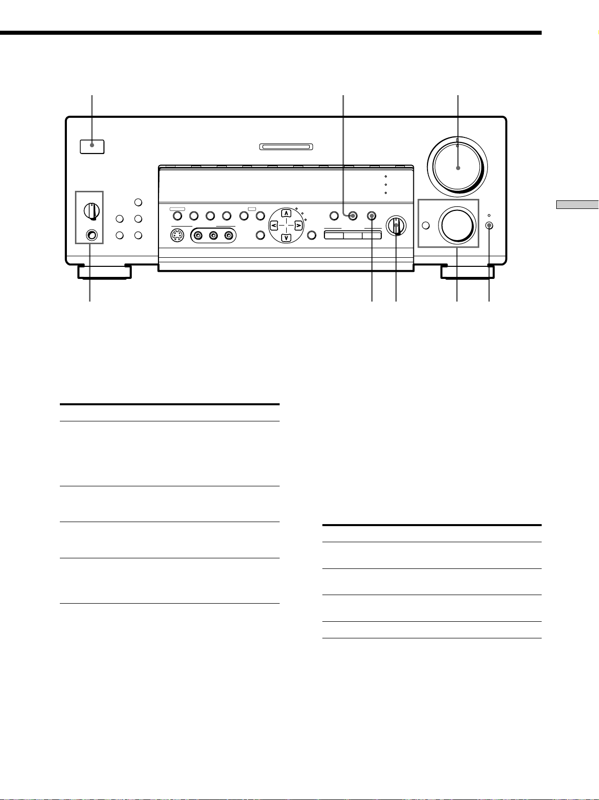
INDEX
SET UP
4
EQ
5.1
INPUT
SOUND FIELD
INPUT
MODE
ON/OFF
GENRE MODE ON/OFF
SOUND FIELD
EQ
BASS BOOST
BALANCE
•
•
•
LR
MASTER VOLUME
•
46
•
•
•
3
•
•
•
2
•
•
•
1
•
•
•
0
MODE MUTING
1 5
MULTI CHANNEL DECODING
VIDEO 1
VIDEO 2 VIDEO 3 DVD TV/LD TAPE MD/DAT CD TUNER PHONO
g
+
A
SPEAKERS
OFF
B
PHONES
A
B
DISPLAY
PRESET TUNING
– +
SHIFT FM/AM
MEMORY FM MODE
VIDEO 3 INPUT
TUNING/
+
– PTY SELECT
RLVIDEOS-VIDEO AUDIO
PTY– –EON RDS
CURSOR
MODE
SURROUND
EQUALIZER
5
•
•
FUNCTION
•
•
•
•
•
•
7
•
•
•
8
•
•
•
9
•
•
•
10
Nomenclature et opérations élémentaires
8
3 Touche INPUT MODE
Sert à sélectionner le mode d’entrée de l’appareil
numérique (DVD, TV/LD et MD/DAT).
A chaque pression sur cette touche, le mode d’entrée
de l’appareil actuellement sélectionné change.
Sélectionnez Pour
AUTO Donner priorité aux signaux
numériques en présence de
liaisons numériques et
analogiques. S’il n’y a pas de
signaux numériques, les signaux
analogiques seront sélectionnés.
ANALOG Spécifier les signaux audio
analogiques fournis aux prises
AUDIO IN (G et D).
DIGITAL (OPTICAL) Spécifier les signaux audio
numériques fournis la prise
DIGITAL OPTICAL.
DIGITAL (COAXIAL) Spécifier les signaux audio
numériques fournis à la prise
d’entrée DIGIT AL COAXIAL
(DVD seulement).
4 Touche 5.1 INPUT
Appuyez sur cette touche pour sélectionner la source
audio raccordée aux prises 5.1 INPUT avec la source
vidéo sélectionnée.
Pour sélectionner une autre source vidéo, utilisez
MODE (2).
2 673
5 Commande MASTER VOLUME
Après avoir mis l’appareil sélectionné sous tension,
tournez la commande pour régler le volume.
6 Touche MUTING
Sert à couper le son. L’indicateur au-dessus de la
touche s’allume quand le son est coupé.
7 BALANCE control
Tournez la commande pour ajuster la balance des
enceintes avant.
8 Sélecteur SPEAKERS
Réglez-le selon les enceintes avant qui doivent être
excitées.
Réglez sur Pour sélectionner
A les enceintes raccordées aux bornes FRONT
B les enceintes raccordées aux bornes FRONT
A+B* les enceintes raccordées aux bornes FRONT
OFF Aucune sortie sur les enceintes avant
Ne sélectionnez pas A+B quand un champ sonore est activé.
*
Prise PHONES
Pour le raccordement d’un casque.
SPEAKERS A
SPEAKERS B
SPEAKERS A et B (liaison parallèle)
• Quand 5.1 INPUT est sélectionné, l’égaliseur,
l’amplification du grave et les effets des champs sonores ne
fonctionnent pas.
• Lorsque vous utilisez le casque, réglez le sélecteur
SPEAKERS sur OFF pour que le son sorte par le casque.
• Quand un champ sonore est activé, le réglage du sélecteur
SPEAKERS sur OFF permet d’obtenir automatiquement un
mixage des deux canaux au niveau du casque.
23
F
Page 78
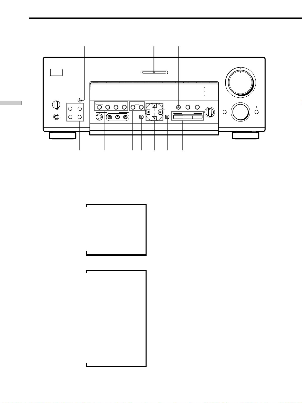
Description des éléments du panneau avant
Nomenclature et opérations élémentaires
9
VIDEO 1
VIDEO 2 VIDEO 3 DVD TV/LD TAPE MD/DAT CD TUNER PHONO
g
+B
A
SPEAKERS
OFF
PHONES
A
B
DISPLAY
PRESET TUNING
– +
SHIFT FM/AM
MEMORY FM MODE
VIDEO 3 INPUT
!£
9 Touche DISPLAY
Appuyez de façon répétée sur cette touche pour
changer les informations qui apparaissent sur
l’afficheur:
Nom d’index de l’appareil*
v
TUNING/
– PTY SELECT
!¡ !™
MASTER VOLUME
5
•
•
•
•
•
•
MULTI CHANNEL DECODING
SOUND FIELD
EQ
BASS BOOST
EQ
5.1
SURROUND
PTY EON– RDS –
+
CURSOR
MODE
RLVIDEOS-VIDEO AUDIO
EQUALIZER
INDEX
SET UP
ON/OFF
GENRE MODE ON/OFF
INPUT
SOUND FIELD
INPUT
MODE
BALANCE
•
•
•
LR
46
•
•
•
3
•
•
•
2
•
•
•
1
•
•
•
0
MODE MUTING
FUNCTION
•
•
•
10
•
7
•
•
•
8
•
•
•
9
•
•
0!§ !¶ !•!¢ !∞
* Le nom d’index apparaît seulement si vous en avez affecté un à
l’appareil ou à la station préréglée (voir page 45). Le nom d’index
n’apparaît pas quand des espaces blancs seulement sont
introduits, ou s’il est identique au nom de la touche de fonction.
** Ces indications apparaissent seulement pendant la réception
RDS (voir page 41).
v
Appareil sélectionné
v
Champ sonore appliqué à l’appareil
Quand la radio est sélectionnée
Nom d’index de la station préréglée* ou nom de
v
la chaîne de programme**
v
Fréquence
v
Indication du type de programme**
v
Texte radio**
v
Heure actuelle**
v
Champ sonore appliqué à la gamme ou à la
station préréglée
!º Utilisez les touches suivantes pour bénéficier d’un son
surround.
Pour les détails, voir “Utilisation du son surround” à
partir de la page 26.
Touche SOUND FIELD GENRE
Appuyez de façon répétée sur cette touche pour
sélectionner le groupe de champs sonores souhaité.
Touche SOUND FIELD MODE
Appuyez sur cette touche pour sélectionner un champ
sonore du groupe sélectionné.
Touche SOUND FIELD ON/OFF
Appuyez sur cette touche pour mettre en ou hors
service le champ sonore.
!¡ Indicateur MULTI CHANNEL DECODING
Cet indicateur s’allume quand le champ sonore est
activé et l’appareil décode des signaux enregistrés
dans le format multicanaux.
24
F
Page 79

!™ Touche EQ ON/OFF
Sert à mettre l’égaliseur en ou hors service.
L’indicateur EQ s’allume quand l’égaliseur est en
service.
Lorsque vous ajustez l’égaliseur avec les paramètres
EQUALIZER du menu CURSOR MODE (page 34), les
réglages sont automatiquement sauvegardés et
peuvent être rappelés en mettant l’égaliseur en
service.
z Si vous voulez bénéficier d’un son de haute qualité
Procédez de la façon suivante pour contourner les circuits de
champs sonores, d’effet sonore et d’amplification du grave.
1 Appuyez sur BASS BOOST de la télécommande pour
éteindre l’indicateur BASS BOOST.
2 Appuyez sur EQ ON/OFF pour éteindre l’indicateur EQ.
3 Appuyez sur SOUND FIELD ON/OFF pour éteindre
l’indicateur SOUND FIELD.
Vous obtiendrez un son entièrement fidèle à la source de
programme.
!£ Les touches suivantes servent au fonctionnement du
tuner intégré. Pour les détails, voir “Réception radio”
à partir de la page 37.
Touches PRESET TUNING +/–
Servent à parcourir toutes les stations radio préréglées.
Touche SHIFT
Sert à sélectionner une page mémoire pour les stations
préréglées.
Touche FM/AM
Sert à sélectionner la gamme FM ou AM.
!¢ Les touches suivantes servent au fonctionnement du
tuner intégré. Pour les détails, voir “Réception radio”
à partir de la page 37.
Touche MEMORY
Sert à mémoriser une station pour la prérégler.
Touche FM MODE
Si “STEREO” clignote sur l’afficheur et si la réception
FM stéréo est de mauvaise qualité, appuyez sur cette
touche. Vous n’aurez pas d’effet stéréo mais le son sera
meilleur.
Touches TUNING/PTY SELECT +/–
Sert à parcourir toutes les stations radio disponibles.
Sert aussi à sélectionner les types de programme
pendant l’utilisation de la fonction PTY.
!∞ Les touches suivantes servent au fonctionnement du
tuner intégré. Pour les détails, voir “Utilisation du
radioguidage (RDS)” à partir de la page 41.
Touche EON
Appuyez sur cette touche pour que l’ampli-tuner
accorde automatiquement une station diffusant des
bulletins routiers, des actualités ou des programmes
d’information. La touche EON ne fonctionne pas
pendant la réception AM.
!§ Touche CURSOR MODE
Appuyez de façon répétée sur cette touche pour
sélectionner un des trois modes curseur suivants.
L’indicateur du mode curseur sélectionné s’allume. Il
s’éteint quand vous appuyez sur la touche SET UP.
Quand le mode Vous pouvez
curseur est
SURROUND Changer les différents
paramètres surround (niveau de
l’effet, type de paroi, etc.), ajuster
le volume et la balance des
enceintes arrière et le volume de
l’enceinte centrale et du caisson
de grave (page 33)
EQUALIZER Ajuster la courbe d’égalisation
(grave/médium/aigu) des
enceintes avant, centrale et
arrière (page 34).
Appuyez sur EQ ON/OFF pour
mettre l’égaliseur en service.
INDEX Entrer un nom d’index pour les
stations préréglées et les sources
de programme (page 45)
!¶ Touches curseur ( / / / )
Après avoir appuyé sur la touche CURSOR MODE ou
SET UP, utilisez ces touches pour faire certains
réglages (voir pages 15, 17, 33, 34 et 46).
!• Touche SET UP
Appuyez de façon répétée sur cette touche pour
sélectionner une des trois indications suivantes.
L’indication sélectionnée apparaît sur l’afficheur et
vous pouvez ensuite effectuer divers réglages avec les
touches curseur.
Si vous avez affiché Vous pouvez
SPEAKER SETUP Spécifier la taille des enceintes
avant, centrale, arrière, la
position des enceintes arrière et
l’emploi ou non d’un caisson de
grave (page 15)
SPEAKER DISTANCE Spécifier la distance des enceintes
avant, centrale et arrière et l’unité
de mesure (page 17)
OTHER Régler l’affichage sur un des
quatre niveaux de luminosité
(page 46)
Nomenclature et opérations élémentaires
Touche PTY
Sert à parcourir les stations par type de programme.
La touche PTY ne fonctionne pas pendant la réception
AM.
25
F
Page 80

Utilisation du son surround
Ce chapitre indique comment régler
l’ampli-tuner pour obtenir un son
surround. Vous bénéficierez aussi
d’un son surround multicanaux à la
lecture de lagiciels codés dans le
format Dolby Digital ou DTS.
Vous pouvez obtenir un son surround en sélectionnant
simplement un des modes préprogrammés de l’amplituner. Ainsi, vous pourrez restituer chez vous le son
vivant et omniprésent d’un cinéma ou d’une salle de
concert. Vous pouvez aussi personnaliser chaque mode
sonore en réglant les divers paramètres surround.
Les modes sonores sont classés par type dans quatre
groupes de base, appelés “genres”. Vous trouverez cidessous une explication élémentaire de chaque genre.
Pour des informations détaillées au sujet des modes
sonores disponibles dans chaque genre, voir pages 28 à 30.
CINEMA
Les modes sonores du genre CINEMA doivent être
utilisés pour les films (DVD, LD, etc.) codés dans le
format surround multicanaux ou Dolby Pro Logic.
Ce mode décode non seulement le son surround mais il
inclut aussi des modes sonores ajoutant la réflexion et la
réverbération typiques des cinémas. Les modes sonores
de ce genre agissent peu sur les sources stéréo à deux
voies (CD, MD, etc.).
VIRTUAL 3D
Ce genre contient des applications attrayantes du Digital
Cinema Sound, une technologie de traitement du signal
sonore numérique mise au point par Sony. Ces modes
sonores décalent le son par rapport à la position de
l’acteur pour simuler la présence de plusieurs acteurs
“virtuels”. Comme le genre CINEMA, ce genre est surtout
efficace avec les films codés dans le format surround
multicanaux.
MUSIC etc.
Les modes sonores de ce genre sont prévus pour les
sources audio ordinaires (comme les CD) et les émissions
de télévision.
Ces modes ajoutent de la réverbération au signal de la
source pour créer des champs sonores omniprésents qui
restituent l’atmosphère d’une salle de concert ou d’un
stade (etc.). Utilisez les modes de ce genre pour les
sources sonores à deux voies et les retransmissions stéréo
de programmes sportifs ou de concerts musicaux.
A.F.D.
Ce genre contient le mode sonore “Auto Format
Decoding” qui restitue le son tel qu’il a été codé, sans
réverbération complémentaire (etc.).
26
Pour bénéficier d’un son surround parfait, vous devez
indiquer le nombre et l’emplacement de vos enceintes.
(Voir “Configuration du surround multicanaux” à partir
de la page 14 pour le réglage des paramètres d’enceintes
avant l’utilisation du son surround.
Touches curseur
EQ ON/OFF
MASTER VOLUME
5
•
•
•
•
•
•
46
MULTI CHANNEL DECODING
VIDEO 1
VIDEO 2 VIDEO 3 DVD TV/LD TAPE MD/DAT CD TUNER PHONO
g
DISPLAY
SPEAKERS
A
B
OFF
A
+B
PRESET TUNING
– +
PHONES
SHIFT FM/AM
MEMORY FM MODE
VIDEO 3 INPUT
– PTY SELECT
TUNING/
+
RLVIDEOS-VIDEO AUDIO
PTY EON– RDS –
SURROUND
ON/OFF
EQUALIZER
INDEX
CURSOR
SET UP
MODE
GENRE MODE ON/OFF
SOUND FIELD
EQ
BASS BOOST
EQ
5.1
INPUT
INPUT
MODE
BALANCE
•
SOUND FIELD
•
•
LR
CURSOR MODE
SOUND FIELD GENRE
SOUND FIELD MODE
SOUND FIELD ON/OFF
F
•
•
•
•
•
3
•
•
•
2
•
•
•
1
•
•
•
•
•
0
10
FUNCTION
MODE MUTING
•
7
•
•
•
8
•
•
•
9
•
Page 81

Brève description des touches utilisées
pour le son surround
Sélection d’un champ sonore
Touches curseur ( / / / ): Après avoir appuyé sur
la touche CURSOR MODE ou sur la touche SET UP,
utilisez ces touches pour faire le réglage actuel.
Touche EQ ON/OFF: Sert à mettre l’égaliseur en ou hors
service.
Touche CURSOR MODE: Appuyez de façon répétée pour
allumer l’indicateur SURROUND ou EQUALIZER et
personnaliser un champ sonore.
Touche SOUND FIELD GENRE: Sert à sélectionner le
groupe (genre) de champs sonores souhaité.
Touche SOUND FIELD MODE: Sert à sélectionner un
champ sonore du genre sélectionné.
Touche SOUND FIELD ON/OFF: Sert à mettre en ou hors
service le champ sonore.
Vous pouvez bénéficier du son surround en sélectionnant
simplement le champ sonore préprogrammé le mieux
adapté au programme écouté.
1 Appuyez sur SOUND FIELD ON/OFF pour mettre le
champ sonore en service.
Le champ sonore actuellement sélectionné est indiqué
sur l’afficheur.
2 Appuyez de façon répétée sur SOUND FIELD GENRE
pour sélectionner un groupe (genre) de champs
sonores, puis sur SOUND FIELD MODE pour
sélectionner le champ sonore souhaité.
Voir le tableau à partir de la page 28 pour les détails
sur chaque champ sonore.
z
L’ampli-tuner mémorise le dernier champ sonore sélectionné
pour chaque source de programme (Liaison de champ sonore)
Chaque fois que vous sélectionnez une source de programme, le
dernier champ sonore appliqué à cette source est
automatiquement réutilisé. Par exemple, si vous écoutez un CD
avec le champ sonore STADIUM, changez de source de
programme puis revenez au CD, STADIUM sera à nouveau
appliqué au CD. Dans le cas de la radio, les champs sonores sont
mémorisés séparément pour les gammes AM ou FM et pour
toutes les stations préréglées.
Utilisation du son surround
z
Vous pouvez identifier un logiciel codé en Dolby Surround
grâce à l’indication sur l’emballage
Utilisez des disques portant le logo . Pour la lecture en
Dolby Digital (AC-3) vous devez utiliser des disques portant ce
logo.
Remarques
• Ne sélectionnez pas les deux paires d’enceintes (A+B) avec le
sélecteur SPEAKERS quand vous utilisez les champs sonores.
• Les champs sonores sont désactivés lorsque la source de
programme raccordée aux prises 5.1 INPUT est sélectionnée.
27
F
Page 82

Sélection d’un champ sonore
Champ sonore Effet Remarques
GENRE : CINEMA
NORMAL SURROUND
Un logiciel contenant des signaux audio surround
multicanaux est reproduit comme il a été enregistré.
Un logiciel contenant des signaux audio à 2 voies est
décodé en Dolby Pro Logic pour créer des effets
surround.
Utilisation du son surround
CINEMA STUDIO A
CINEMA STUDIO B
CINEMA STUDIO C
NIGHT THEATER
MONO MOVIE
STEREO MOVIE
GENRE : VIRTUAL 3D
VIRTUAL MULTI REAR
Reproduit les caractéristiques sonores du studio de
production cinématographique “Cary Grant Theater”
de Sony Pictures Entertainment.
Reproduit les caractéristiques sonores du studio de
production cinématographique “Kim Novak Theater”
de Sony Pictures Entertainment.
Reproduit les caractéristiques sonores du studio
d’arrangement musical de Sony Pictures Entertainment.
Permet d’obtenir une ambiance de cinéma lors de la
visualisation de films à faible volume, en particulier la
nuit.
Crée une ambiance de cinéma avec les films dont les
bandes sonores sont en monophonie.
Crée une ambiance de cinéma avec les films dont les
bandes sonores sont en stéréophonie.
Emploie la représentation sonore 3D pour créer 3 paires
d’enceintes arrière virtuelles à partir d’une seule paire
d’enceintes arrière.
C’est le mode standard. Excellent pour
regarder la plupart des films.
Ce mode est idéal pour regarder les films
de science-fiction ou d’action contenant
une grande quantité d’effets sonores.
Ce mode est idéal pour les comédies
musicales et les films classiques où la
musique est sur la piste sonore.
LCR
SIDE*
RSLS
LS
RS
RSLS
28
LCR
MIDDLE*
RSLS
LS
LCR
RS
RSLS
BEHIND*
RSLS
LS
RS
RSLS
* Voir
page 16
F
Page 83

Champ sonore Effet Remarques
GENRE : VIRTUAL 3D (suite)
VIRTUAL MULTI DIMENSION
Emploie la représentation sonore 3D pour créer tout un
éventail d’enceintes arrière virtuelles, positionnées plus
haut que l’auditeur, à partir d’une seule paire d’enceintes
arrière. Ce mode crée 5 paires d’enceintes virtuelles qui
entourent l’auditeur à un angle de 30° environ d’élévation.
SIDE*
LCR
RSLS
VIRTUAL THEATER A
VIRTUAL THEATER B
VIRTUAL THEATER C
VIRTUAL ENHANCED A
VIRTUAL ENHANCED B
Ajoute la représentation sonore 3D de VIRTUAL MULTI
DIMENSION à CINEMA STUDIO A. Reproduit les
caractéristiques sonores du “Cary Grant Theater” et crée 5
paires d’enceintes virtuelles qui entourent l’auditeur (à un
angle de 30° environ d’élévation) à partir d’une seule paire
d’enceintes arrière réelles.
Ajoute la représentation sonore 3D de VIRTUAL MULTI
DIMENSION à CINEMA STUDIO B. Reproduit les
caractéristiques sonores du “Kim Novak Theater” et crée 5
paires d’enceintes virtuelles qui entourent l’auditeur (à un
angle de 30° environ d’élévation) à partir d’une seule paire
d’enceintes arrière réelles.
Ajoute la représentation sonore 3D de VIRTUAL MULTI
DIMENSION à CINEMA STUDIO C. Reproduit les
caractéristiques sonores d’un studio d’arrangement musical
et crée 5 paires d’enceintes virtuelles qui entourent
l’auditeur (à un angle de 30° environ d’élévation) à partir
d’une seule paire d’enceintes arrière réelles.
Emploie la représentation sonore 3D pour créer 3 paires de
d’enceintes arrière virtuelles avec le son des enceintes
avant, sans utiliser les enceintes arrière réelles.
Emploie la représentation sonore 3D pour créer 1 paire
d’enceintes arrière virtuelles avec le son des enceintes
avant, sans utiliser les enceintes arrière réelles.
MIDDLE*
BEHIND*
LS
LCR
LS
LCR
LS
LCR
LCR
RS
RSLS
RSLS
RS
RSLS
RSLS
RS
RSLS
* Voir
RSLS
RSLS
Utilisation du son surround
page 16
VIRTUAL SEMI-MULTI
DIMENSION
VIRTUAL SEMI-THEATER A
Emploie la représentation sonore 3D pour créer une paire
d’enceintes arrière virtuelles avec le son des enceintes
avant, sans utiliser les enceintes arrière actuelles. Ce mode
crée 5 paires d’enceintes virtuelles qui entourent l’auditeur
à un angle de 30° d’élévation.
Ajoute la représentation sonore 3D de VIRTUAL SEMIMULTI DIMENSION à CINEMA STUDIO A. Reproduit les
caractéristiques sonores du “Cary Grant Theater” et crée 5
paires d’enceintes virtuelles qui entourent l’auditeur à un
angle de 30° environ d’élévation avec le son des enceintes
avant, sans utiliser les enceintes arrière réelles.
LS
LCR
LS
RS
RSLS
RSLS
RS
RSLS
29
F
Page 84

Utilisation du son surround
Sélection d’un champ sonore
Champ sonore Effet Remarques
GENRE : VIRTUAL 3D (suite)
VIRTUAL SEMI-THEATER B
VIRTUAL SEMI-THEATER C
Ajoute la représentation sonore 3D de VIRTUAL SEMIMULTI DIMENSION à CINEMA STUDIO B. Reproduit les
caractéristiques sonores du “Kim Novak Theater” et crée 5
paires d’enceintes virtuelles qui entourent l’auditeur à un
angle de 30° environ d’élévation avec le son des enceintes
avant, sans utiliser les enceintes arrière réelles.
Ajoute la représentation sonore 3D de VIRTUAL SEMIMULTI DIMENSION à CINEMA STUDIO C. Reproduit les
caractéristiques sonores d’un studio d’arrangement musical
et crée 5 paires d’enceintes virtuelles qui entourent
l’auditeur à un angle de 30° environ d’élévation avec le son
des enceintes avant, sans utiliser les enceintes arrière
réelles.
GENRE : MUSIC ETC.
SMALL HALL
LARGE HALL
Reproduit l’acoustique d’une petite salle de concert
rectangulaire.
Idéal pour restituer des sons doux.
Reproduit l’acoustique d’une grande salle de concert
rectangulaire.
LCR
RSLS
LS
RS
RSLS
OPERA HOUSE
Reproduit l’acoustique d’un opéra.
Idéal pour les comédies musicales et
l’opéra.
JAZZ CLUB
DISCO/CLUB
Reproduit l’acoustique d’un club de jazz.
Reproduit l’acoustique d’une discothèque/d’un club de
danse.
CHURCH
LIVE HOUSE
ARENA
Reproduit l’acoustique d’une église en pierre.
Reproduit l’acoustique d’un club de 300 places
Reproduit l’acoustique d’une salle de concert de 1000
Idéal pour la musique rock ou pop.
places.
STADIUM
Reproduit l’ambiance d’un grand stade en plein air.
Idéal pour les événements sportifs ou les
sons électriques (amplifiés).
GAME
Permet d’obtenir un impact sonore maximal pour les jeux
vidéo.
Réglez la console vidéo sur le mode
stéréo avec les jeux pouvant restituer le
son en stéréo.
GENRE : A.F.D.
AUTO FORMAT DECODING Vous pouvez utiliser ce mode comme
Remarque
Les effets fournis par les champs VIRTUAL THEATER A, B et C peuvent entraîner une augmentation du bruit sur le signal de lecture.
Détecte automatiquement le type de signal audio fourni
(Dolby Digital, DTS, Dolby Pro Logic ou 2 voies stéréo)
et effectue le décodage adéquat. Ce mode présente le
son tel qu’il a été enregistré/codé, sans ajouter d’effets.
référence. Réglez l’égaliseur sur OFF
quand vous utilisez ce mode pour que le
son soit restitué tel qu’il a été enregistré.
30
F
Page 85

Signification des diverses indications du surround multicanaux
123 45 6 7
OPTICAL COAXIAL
AC-3RFMPEGDTSDUAL
DIGITAL
a
PRO LOGIC
!¡
1 OPTICAL
S’allume quand le signal source est un signal
numérique fourni par la prise OPTICAL.
2 COAXIAL
S’allume quand le signal source est un signal
numérique fourni par la prise COAXIAL.
3 a DIGITAL
S’allume quand le champ sonore est activé et que
l’appareil décode les signaux enregistrés dans le
format Dolby Digital (AC-3).
4 Indicateurs des voies de lecture
Ces lettres s’allument pour indiquer les voies en cours
de lecture.
L: Avant gauche R: Avant droite
C: Centrale (monophonie) LS: Gauche surround
RS: Surround droite
S: Surround (monophonie ou les composantes arrière
obtenues par le traitement Pro Logic)
Les cadres qui entourent les lettres s’allument pour
indiquer les enceintes utilisées pour restituer chaque
voie.
Voir la page suivante pour les détails concernant les
indicateurs des voies de lecture.
5 L.F.E.
Les lettres “L.F.E.” s’allument quand le disque en
cours de lecture contient le canal LFE (Low Frequency
Effect).
Quand le son du signal du canal LFE est reproduit, les
barres sous les lettres s’allument pour indiquer le
niveau. Comme le signal LFE n’est pas enregistré dans
l’intégralité du signal fourni, l’éclairage des barres
peut fluctuer (et s’éteindre) pendant la lecture.
L.F.E.LLSCSR
RS
6 S.WOOFER
S’allume quand l’option caisson de grave est réglée
sur “YES” et que l’appareil détecte que le disque en
cours de lecture ne contient pas le signal de la voie
LFE. Quand cet indicateur est allumé, l’appareil crée
un signal de grave à partir des composantes basses
fréquences des voies avant.
7 Indicateurs radio
Ces indicateurs s’allument quand des stations radio
sont accordées, etc. Voir pages 37 à 43 pour le
fonctionnement de la radio.
8 D. RANGE
S’allume quand la compression de plage dynamique
est validée. Voir pages 33 et 34 pour ajuster la plage
dynamique.
9 PRO LOGIC
S’allume quand l’appareil applique aux signaux à
deux voies le traitement Pro Logic pour fournir les
signaux sur les voies centrale et surround.
0 DTS
S’allume quand les signaux DTS sont fournis.
Remarques
• A la lecture d’un disque de format DTS, veillez à effectuer
des liaisons numériques et à NE PAS régler INPUT MODE
sur ANALOG (voir 3 à la page 23).
• Du bruit peut être audible au début de la lecture d’un LD
ou CD de format DTS. Il ne s’agit pas d’un
dysfonctionnement.
!¡ AC-3
S’allume quand des signaux Dolby Digital (AC-3) sont
fournis.
S.WOOFER STEREO RDS
D.RANGE EQ MONO TA NEWS INFO
MEMORY
890
Utilisation du son surround
31
F
Page 86

Signification des diverses indications du surround multicanaux
Indication des voies de lecture
L’afficheur indique les voies en cours de lecture et les enceintes utilisées. Les lettres (L, C, R, etc.) s’allument pour indiquer
les voies reproduites. Les cadres qui entourent les lettres s’allument pour indiquer les enceintes qui sont utilisées. Les
indications affichées dépendent du nombre d’enceintes raccordées. Voir la colonne “Configuration des enceintes et
indication des voies de lecture” dans le tableau suivant.
Le nombre de voies contenues dans le signal fourni à l’ampli-tuner est également indiqué. Voir la colonne “Indication des
voies d’entrée” dans le tableau suivant.
Bien que le tableau suivant montre presque toutes les configurations possibles avec les signaux surround multicanaux, les
plus courantes sont signalées par “
”.
Utilisation du son surround
Format
d’enregistrement
(Avant/Arrière)
1/0
2/0*
3/0
2/1
3/1
2/2
3/2
2/0**
Indication des voies d’entrée
DOLBY DIGITAL [1/0]
dts [1/0]
DOLBY DIGITAL [2/0]
dts [2/0]
DOLBY DIGITAL [3/0]
dts [3/0]
DOLBY DIGITAL [2/1]
dts [2/1]
DOLBY DIGITAL [3/1]
dts [3/1]
DOLBY DIGITAL [2/2]
dts [2/2]
DOLBY DIGITAL [3/2]
dts [3/2]
DOLBY DIGITAL [2/0]
dts [2/0]
Configuration des enceintes et indication des voies de lecture
Toutes les enceintes
présentes
DIGITALaC
DTS
L R L R L R L R
DTS
DTS
DTS
DTS
DTS
DTS
PRO LOGIC
DTS
L
DIGITALaL C R
L
DIGITALaLSR
L
DIGITALaL CSR
L
DIGITALaLLSR
L
LS
DIGITALaLLSC R
L
LS
L CSR
L
Enceintes arrière
DIGITALaC
C
DTS
R
DTS
DIGITALaL C R
C R
DTS
DIGITALaL
R
S
DTS
DIGITALaL CSR
CSR
DTS
DIGITALaLLSR
RS
R
RS
DTS
DIGITALaLLSC R
RS
C R
RS
DTS
PRO LOGIC
CSR
DTS
absentes
L
L
L
L
L
LS
L
LS
L CSR
L
Enceinte centrale
DIGITALaC
C
DTS
R
DTS
DIGITALaL CR
C R
DTS
R
S
S
CSR
C R
CSR
DIGITALaLSR
R
DTS
DIGITALaL CSR
DTS
DIGITALaLLSR
RS
R
RS
DTS
DIGITALaLLSCR
RS
RS
DTS
PRO LOGIC
DTS
absente
L
L
L
L
L
LS
L
LS
L CSR
L
C
CR
S
CSR
CR
CSR
Enceintes arrière/
centrale absentes
DIGITALaC
DTS
R
DTS
DIGITALaL CR
DTS
DIGITALaL
R
DTS
DIGITALaL CSR
DTS
DIGITALaLLSR
RS
R
RS
DTS
DIGITALaLLSCR
RS
RS
DTS
PRO LOGIC
DTS
C
L
CR
L
S
L
S
CSR
L
L
LS
CR
L
LS
L CSR
CSR
L
R
R
R
RS
R
RS
RS
RS
DOLBY PRO LOGIC
STEREO PCM**
PRO LOGIC
L CSR
L R L R L R L R
PRO LOGIC
L CSR
* Sans Pro Logic
**Quand le Pro Logic est activé ou un mode sonore. CINEMA ou VIRTUAL 3D est sélectionné.
F
32
PRO LOGIC
L CSR
PRO LOGIC
L CSR
Page 87

Personnalisation des champs sonores
Personnalisation des champs sonores
En réglant les paramètres surround et la courbe
d’égalisation des enceintes avant et centrale, vous pouvez
personnaliser les champs sonores en tenant compte de
votre situation d’écoute particulière.
Lorsqu’un champ sonore a été préréglé, les changements
restent mémorisés indéfiniment (à moins que l’amplituner soit débranché pendant une semaine environ). Vous
pouvez changer un champ sonore personnalisé quand
vous voulez en effectuant simplement de nouveaux
réglages.
Voir le tableau de la page 36 pour les paramètres
disponibles pour chaque champ sonore.
Pour tirer le meilleur parti du son
surround multicanaux
Positionnez les enceintes et effectuez les opérations
décrites dans “Configuration du surround multicanaux” à
partir de la page 14 avant de personnaliser un champ
sonore.
Réglage des paramètres surround
Le menu SURROUND contient certains paramètres qui
vous permettent de personnaliser divers aspects du
champ sonore actuel. Les réglages disponibles dans ce
menu sont sauvegardés individuellement pour chaque
champ sonore.
1 Commencez la lecture d’une source de programme
codée avec le son surround multicanaux.
2 Appuyez de façon répétée sur CURSOR MODE
jusqu’à ce que l’indicateur SURROUND s’allume.
3 Appuyez sur les touches curseur ( ou ) pour
sélectionner le paramètre que vous voulez ajuster.
4 Appuyez sur les touches curseur ( ou ) pour
sélectionner le réglage souhaité. Le réglage est
automatiquement validé.
TYPE DE PAROI (WALL)
Réglage initial : Point central
Quand le son se réfléchit sur un matériau doux, comme
des rideaux, les éléments des hautes fréquences sont
réduits. Une paroi dure réfléchit énormément le son et
influence guère la réponse en fréquence du son réfléchi.
Ce paramètre vous permet de contrôler le niveau des
hautes fréquences pour modifier le caractère acoustique
de votre environnement en simulant une paroi douce (S)
ou dure (H).
Le point central désigne une paroi neutre, par exemple de
bois.
RÉVERBÉRATION (REVERB)
Réglage initial : Point central
Avant que le son n’atteigne les oreilles de l’auditeur, il est
réfléchi (réverbéré) plusieurs fois entre les murs gauche et
droit, le plafond et le sol. Dans une grande pièce, le son
met plus de temps à rebondir d’une surface à l’autre que
dans une petite pièce. Ce paramètre vous permet de
contrôler l’espacement des premières réflexions pour
simuler une grande pièce (L) ou une petite pièce (S).
• La réverbération peut être ajustée de ±8 de S (petite
pièce, –8) à L (grande pièce, +8) en 17 paliers.
• Le point central (0) désigne une pièce normale sans
réglage.
NIVEAU DE MIXAGE LFE (LFE MIX)
Réglage initial : 0 dB
Ce paramètre vous permet d’atténuer le niveau de la voie
LFE (effet basse fréquence) fournie par le caisson de grave
sans affecter le niveau des basses fréquences transmises
au caisson par les voies avant, centrale ou arrière à travers
le circuit de réaiguillage du grave Dolby Digital (AC-3).
• Le niveau peut être réglé par paliers de 1 dB de –20 dB à
0 dB (niveau linéaire). 0 dB fournit le signal LFE
complet au niveau de mixage voulu par l’ingénieur du
son.
• La sélection de MUTING coupe le son de la voie LFE
sur le caisson de grave. Cependant, les sons de basses
fréquences des enceintes avant, centrale ou arrière sont
fournis par le caisson de grave en fonction des réglages
effectués pour chaque enceinte lors de la configuration
des enceintes (page 15).
Utilisation du son surround
NIVEAU DE L’EFFT (EFFECT)
Réglage initial : (dépend du mode sonore)
Ce paramètre sert à ajuster la “présence” de l’effet
surround du son cinématographique numérique actuel.
33
F
Page 88

Personnalisation des champs sonores
Utilisation du son surround
COMPRESSION DE PLAGE DYNAMIQUE (D. RANGE
COMP)
Réglage initial : OFF (désactivé)
Permet de comprimer la plage dynamique de la piste
sonore, ce qui peut être utile pour regarder des films à bas
volume la nuit.
• OFF reproduit la piste sonore sans compression.
• STD reproduit la piste sonore avec la plage dynamique
voulue par l’ingénieur du son.
• 0,1 - 0,9 permet de comprimer la plage dynamique par
petits paliers pour obtenir le son souhaité.
• MAX fournit une compression considérable de la plage
dynamique.
Remarque
La compression de la plage dynamique n’est pas possible avec les
sources DTS.
z
A sujet de la compression de la plage dynamique
Ce paramètre permet de comprimer la plage dynamique d’une
piste sonore en fonction des informations de plage dynamique
contenues dans le signal Dolby Digital. “STD” est la compression
ordinaire, mais comme de nombreuses sources n’ont qu’une
légère compression, vous ne noterez peut-être pas beaucoup la
différence avec les réglages 0,1 - 0,9.
Nous conseillons donc l’utilisation du réglage “MAX”. Il
comprime considérablement la plage dynamique et vous permet
de voir des films la nuit à bas volume. Contrairement aux
limiteurs analogiques, les niveaux sont fixés et garantissent une
compression très naturelle.
NIVEAU CENTRAL (CENTER)
Réglage initial: 0 dB
Permet d’ajuster le niveau de l’enceinte centrale.
• Le niveau peut être ajusté par paliers de 1 dB de –10 dB
à +10 dB.
NIVEAU DU CAISSON (WOOFER)
Réglage initial: 0 dB
Permet d’ajuster le niveau du caisson de grave.
• Le niveau peut être ajusté par paliers de 1 dB de –10 dB
à +10 dB.
Réglage de l’égaliseur
Le menu EQUALIZER vous permet de régler la courbe
d’égalisation (basses, moyennes et hautes fréquences) des
enceintes avant et centrale. Les réglages effectués sont
sauvegardés individuellement pour chaque champ
sonore.
1 Commencez la lecture d’une source de programme
codée dans le format surround multicanaux.
2 Appuyez de façon répétée sur CURSOR MODE
jusqu’à ce que l’indicateur EQUALIZER s’allume.
3 Appuyez sur les touches curseur ( ou ) pour
sélectionner le paramètre que vous voulez ajuster.
BALANCE ARRIÈRE (REAR)
Réglage initial: centre
Permet de régler la balance entre les enceintes arrière
gauche et droite.
• La balance peut être ajustée de ±8 dB par paliers de
1 dB.
• Ce réglage peut aussi être ajusté directement avec la
télécommande. Voir “Réglage du volume des enceintes”
(page 18).
NIVEAU ARRIÈRE (REAR)
Réglage initial: 0 dB
Permet de régler le niveau des enceintes arrière (gauche et
droite).
• Le niveau peut être ajusté par paliers de 1 dB de –10 dB
à +10 dB.
• Ce réglage peut aussi être ajusté directement avec la
télécommande. Voir “Réglage du volume des enceintes”
(page 18).
4 Appuyez sur les touches curseur ( ou ) pour
sélectionner le réglage souhaité. Le réglage est
automatiquement validé.
z
Vous pouvez annuler la courbe d’égalisation sans l’effacer
Les réglages de l’égaliseur sont sauvegardés séparément pour
chaque champ sonore. Appuyez sur la touche EQ ON/OFF pour
éteindre l’indicateur EQ.
34
F
Page 89

Réglage des basses des enceintes avant (Niveau/
Fréquence)
1 Utilisez
fréquence (Hz).
2 Utilisez
Répétez ces opérations jusqu’à ce que vous obteniez le son
souhaité.
Niveau
(dB)
• Le niveau peut être ajusté de ±10 dB par paliers de 1 dB.
• La fréquence peut être ajustée de 100 Hz à 1,0 kHz en 21
paliers.
Réglage des médiums des enceintes avant
(Niveau/Fréquence)
Faites le réglage indiqué dans “Réglage des basses des
enceintes avant”.
• Le niveau peut être ajusté de ±10 dB par paliers de 1 dB.
• La fréquence peut être ajustée de 500 Hz à 5,0 kHz en
21 paliers.
Réglage des aigus des enceintes avant (Niveau/
Fréquence)
Faites le réglage indiqué dans “Réglage des basses des
enceintes avant”.
• Le niveau peut être ajusté de ±10 dB par paliers de 1 dB.
• La fréquence peut être ajustée de 1,0 kHz à 10 kHz en
21 paliers.
Réglage des graves de l’enceinte centrale
(Niveau/Fréquence)
Faites le réglage indiqué dans “Réglage des basses des
enceintes avant”.
• Le niveau peut être ajusté de ±10 dB par paliers de 1 dB.
• La fréquence peut être ajustée de 100 Hz à 1,0 kHz en
21 paliers.
Réglage des médiums de l’enceinte centrale
(Niveau/Fréquence)
Faites le réglage indiqué dans “Réglage des basses des
enceintes avant”.
• Le niveau peut être ajusté de ±10 dB par paliers de 1 dB.
• La fréquence peut être ajustée de 500 Hz à 5,0 kHz en
21 paliers.
/ pour sélectionner le niveau (dB) ou la
/ pour faire le réglage.
BASS
Fréquence
(Hz)
Fréquence
(Hz)
Fréquence
(Hz)
TREBLEMID
Réglage des aigus de l’enceinte centrale (Niveau/
Fréquence)
Faites le réglage indiqué dans “Réglage des basses des
enceintes avant”.
• Le niveau peut être ajusté de ±10 dB par paliers de 1 dB.
• La fréquence peut être ajustée de 1,0 kHz à 10 kHz en
21 paliers.
Réglage des basses des enceintes arrière (Niveau/
Fréquence)
Faites le réglage indiqué dans “Réglage des basses des
enceintes avant”.
• Le niveau peut être ajusté de ±10 dB par paliers de 1 dB.
• La fréquence peut être ajustée de 100 Hz à 1,0 kHz en
21 paliers.
Utilisation du son surround
Réglage des médiums des enceintes arrière
(Niveau/Fréquence)
Faites le réglage indiqué dans “Réglage des basses des
enceintes avant”.
• Le niveau peut être ajusté de ±10 dB par paliers de 1 dB.
• La fréquence peut être ajustée de 500 Hz à 5,0 kHz en
21 paliers.
Réglage des aigus des enceintes arrière (Niveau/
Fréquence)
Faites le réglage indiqué dans “Réglage des basses des
enceintes avant”.
• Le niveau peut être ajusté de ±10 dB par paliers de 1 dB.
• La fréquence peut être ajustée de 1,0 kHz à 10 kHz en
21 paliers.
Rétablissement des réglages usine des
champs sonores
1 Si l’ampli-tuner est sous tension, appuyez sur 1/u
pour le mettre hors tension.
2 Tout en maintenant SOUND FIELD ON/OFF
enfoncée, appuyez sur 1/u.
“SURR CLEAR!” apparaît sur l’afficheur et tous les
champs sonores d’origine sont rétablis.
35
F
Page 90

Utilisation du son surround
Personnalisation des champs sonores
Paramètres réglables pour chaque champ sonore
Champ EFFECT WALL REVERB LFE D.RANGE REAR REAR CENTER WOOFER
sonore GENRE MODE LEVEL TYPE TIME MIX COMP BAL. LEVEL LEVEL LEVEL EQ
Désactivé — — rr r
Activé CINEMA NORMAL SURROUND rr rrr rr
CINEMA STUDIO A rrrrrrrr
CINEMA STUDIO B rrrrrrrr
CINEMA STUDIO C rrrrrrrr
NIGHT THEATER rr rr r rr r rr
MONO MOVIE rr rr r rr r rr
STEREO MOVIE rr rr r rr r rr
VIRTUAL 3D V. MULTI REAR rrrrrrrr
V. MULTI DIMENSION rrrrrrrr
V. THEATER A rrrrrrrr
V. THEATER B rrrrrrrr
V. THEATER C rrrrrrrr
V. ENHANCED A rrr rrr
V. ENHANCED B rrr rrr
V. SEMI-M.DIMENSION rrr rrr
V. SEMI-THEATER A rrr rrr
V. SEMI-THEATER B rrr rrr
V. SEMI-THEATER C rrr rrr
MUSIC etc. SMALL HALL rr rr r rr r rr
LARGE HALL rr rr r rr r rr
OPERA HOUSE rr rr r rr r rr
JAZZ CLUB rr rr r rr r rr
DISCO/CLUB rr rr r rr r rr
CHURCH rrrr r rr r rr
LIVE HOUSE rr rr r rr r rr
ARENA rr rr r rr r rr
STADIUM rr rr r rr r rr
GAME rrrr r rr r rr
A.F.D. AUTO FORMAT DECODE rr rrr rr
36
F
Page 91

Réception radio
Ce chapitre indique comment recevoir
des émissions FM ou AM et
présélectionner certaines stations.
Sur cet ampli-tuner, les stations peuvent être accordées de
la façon suivante:
Présélection automatique des stations FM
(AUTOBETIQUE)
L’ampli-tuner est capable de mémoriser automatiquement
jusqu’à 30 stations FM et FM RDS parmi les plus claires
dans l’ordre alphabétique (voir page 38).
Accord direct
Vous indiquez la fréquence de la station que vous voulez
écouter à l’aide des touches numériques de la
télécommande (voir page 39).
Accord automatique
Si vous ne connaissez pas la fréquence de la station
souhaitée, vous pouvez laisser l’appareil faire l’accord
successivement sur toutes les stations disponibles dans la
région (voir page 39).
Accord d’une station préréglée
Après avoir accordé une station en utilisant l’accord direct
ou automatique, vous pouvez la prérégler (voir page 40).
Il vous suffira ensuite d’entrer un code de 2 caractères
pour accorder cette station (voir page 40). Vous pouvez
prérégler jusqu’à 30 stations FM ou AM. L’ampli-tuner
balayera toutes les stations que vous avez préréglées (voir
page 40).
Réception radio
Fonctions RDS
Avec cet ampli-tuner, vous pouvez aussi utiliser le RDS
(Radioguidage) qui permet aux stations radio de
transmettre des informations supplémentaires en même
temps que le signal radio ordinaire. Vous pouvez utiliser
les trois fonctions RDS suivantes:
— Affichage des informations RDS (voir page 41)
— Balayage des stations préréglées selon le type de
programme (voir page 41)
— Utilisation de la fonction EON (voir page 41).
Le RDS ne fonctionne que pour les stations FM*.
* Toutes les stations FM ne transmettent pas de services RDS, et celles
qui en transmettent n’offrent pas toutes les mêmes types de services.
Si vous ne connaissez pas bien le système RDS, consultez votre
société de radiodiffusion locale pour les détails.
Avant de commencer, assurez-vous que vous avez:
• Raccordé les antennes FM et AM à l’ampli-tuner (voir
page 5).
• Sélectionné le système acoustique approprié (voir page
23).
37
F
Page 92
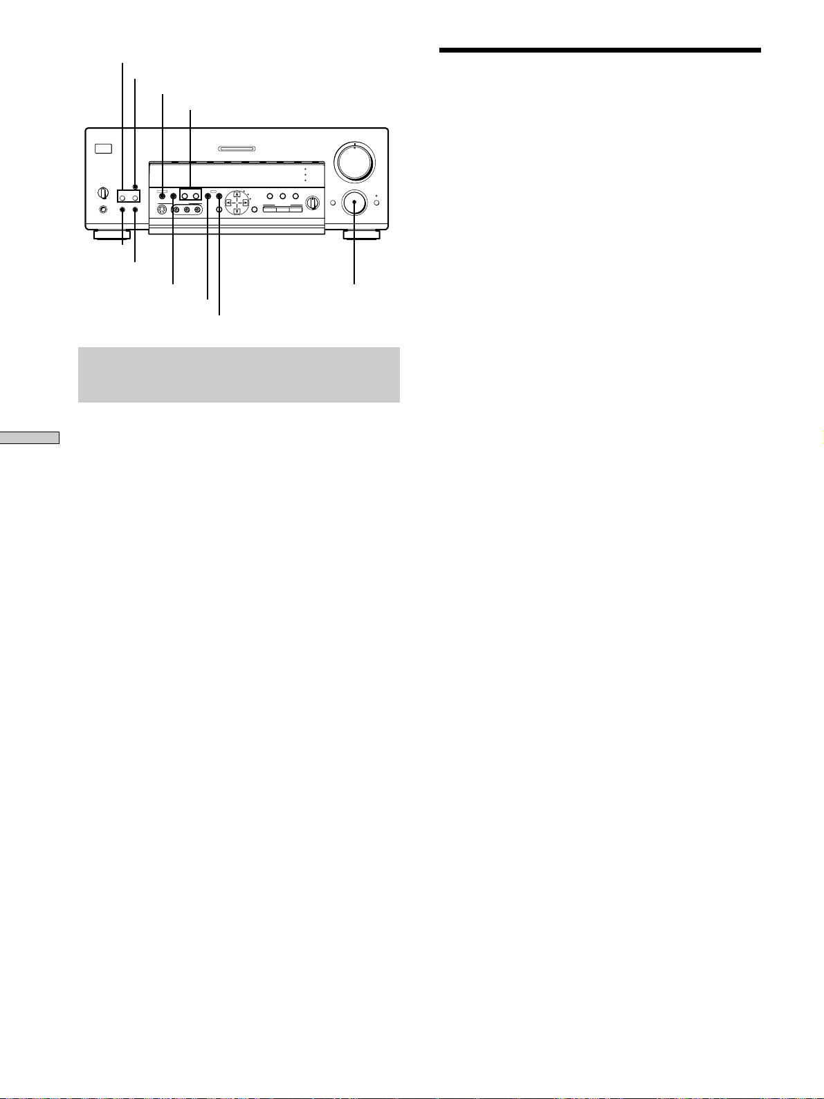
PRESET TUNING +/–
DISPLAY
MEMORY
TUNING/PTY SELECT +/–
VIDEO 1
g
DISPLAY
SPEAKERS
A
B
OFF
+
B
A
PHONES
PRESET TUNING
– +
SHIFT FM/AM
MEMORY FM MODE
SHIFT
FM/AM
MULTI CHANNEL DECODING
VIDEO 2 VIDEO 3 DVD TV/LD TAPE MD/DAT CD TUNER PHONO
VIDEO 3 INPUT
– PTY SELECT
TUNING/
PTY EON– RDS –
+
RLVIDEOS-VIDEO AUDIO
SURROUND
EQUALIZER
INDEX
CURSOR
SET UP
MODE
EQ
5.1
ON/OFF
INPUT
SOUND FIELD
GENRE MODE ON/OFF
SOUND FIELD
EQ
BASS BOOST
INPUT
MODE
BALANCE
LR
PTY
EON
•
•
•
FUNCTIONFM MODE
MASTER VOLUME
5
•
•
•
•
•
•
46
•
•
•
•
3
•
•
•
2
•
•
•
1
•
•
•
•
0
10
FUNCTION
MODE MUTING
•
•
7
9
•
•
•
•
•
8
•
•
•
Présélection automatique
des stations FM (AUTOBETIQUE)
Cette fonction vous permet de mémoriser jusqu’à 30
stations FM et FM RDS sans redondance dans l’ordre
alphabétique.
Seules les stations dont le signal est suffisamment
puissant sont présélectionnées.
Si vous voulez présélectionner des stations FM ou AM
une à une, reportez-vous à “Préréglage de stations radio”
à la page 40.
Pour les détails sur les touches utilisées dans ce
paragraphe, reportez-vous à “Brève description des
touches et commandes utilisées pour la réception radio.”
sur cette page.
Brève description des touches et
commandes utilisées pour la réception
radio
Touche PRESET TUNING +/–: Servent à parcourir toutes
Réception radio
les stations radio préréglées.
Touche DISPLAY: Sert à afficher les informations RDS.
Touche MEMORY: Sert à mémoriser les stations
préréglées.
Touches TUNING/PTY SELECT +/–: Servent à parcourir
toutes les stations radio disponibles.
Commande FUNCTION: Tournez-la pour sélectionner la
radio.
Touche EON: Appuyez sur cette touche pour que l’amplituner change automatiquement de station.
Touche PTY: Sert à parcourir les stations par type de
programme.
Touche FM MODE: Si “STEREO” clignote sur l’afficheur
et si la réception FM stéréo est de mauvaise qualité,
appuyez sur cette touche pour améliorer le son. Vous ne
bénéficierez plus du son stéréo mais les parasites
disparaîtront.
Remarque
Si “STEREO” n’apparaît pas quand une station FM est reçue
normalement, appuyez sur cette touche pour afficher l’indication
“STEREO”.
Touche FM/AM: Appuyez sur cette touche pour
sélectionner la gamme FM ou AM.
1 Appuyez sur 1/u pour mettre l’ampli-tuner hors
tension.
2 Tout en tenant MEMORY enfoncée, appuyez sur
1/u pour remettre l’ampli-tuner sous tension.
“Autobetical select” apparaît sur l’afficheur et l’amplituner parcourt et mémorise toutes les stations FM et
FM RDS dans la zone de diffusion.
Pour les stations RDS, le tuner recherche d’abord les
stations diffusant le même programme, puis mémorise
seulement la station qui a le meilleur signal. Les
stations RDS sélectionnées sont ensuite classées dans
l’ordre alphabétique en fonction du nom de la chaîne
de programme, puis un code de préréglage à deux
caractères leur est attribué. Pour des informations plus
détaillées sur le RDS, voir page 41.
Les stations FM ordinaires reçoivent un code de
préréglage à deux caractères et sont mémorisées après
les stations RDS.
Quand la présélection est terminée, “Autobetical
finish” apparaît un moment sur l’afficheur et l’amplituner fonctionne normalement.
Remarques
• N’appuyez pas sur les touches de l’ampli-tuner et de la
télécommande fournie pendant la présélection autobétique des
stations.
• Si vous changez de région, refaites l’opération précédente pour
mémoriser les stations dans la nouvelle région.
• Pour les détails sur l’accord des stations présélectionnées, voir
page 40.
• Le réglage FM MODE est mémorisé en même temps que la
station.
• Si vous changez la position de l’antenne après la présélection
automatique des stations, les réglages obtenues risquent de ne
plus être valides. Le cas échéant, répétez l’opération pour
présélectionner à nouveau les stations.
Touche SHIFT: Sert à sélectionner une page mémoire (A, B
ou C) pour le préréglage de stations radio ou l’accord de
stations préréglées.
F
38
Page 93

Accord direct
Accord automatique
Utilisez la télécommande fournie pour effectuer
les opérations suivantes
Pour les détails concernant les touches utilisées dans ce
paragraphe, voir le mode d’emploi de la télécommande
fournie.
1 Tournez sur FUNCTION pour sélectionner la radio.
La dernière station reçue est accordée.
2 Appuyez sur FM/AM pour sélectionner la gamme
FM ou AM.
3 Appuyez sur DIRECT (ou D.TUNING).
4 Appuyez sur les touches numériques pour entrer la
fréquence.
Exemple 1: FM 102,50 MHz
bbbb
10250
Exemple 2: AM 1350 kHz
(Il n’est pas nécessaire d’entrer le dernier “0”.)
bbb
1350
Si vous ne pouvez pas accorder une station et
si les nombres entrés clignotent
Vérifiez si vous avez entré la bonne fréquence. Sinon,
répétez les étapes 3 et 4.
Si les nombres entrés continuent de clignoter, la
fréquence n’est pas utilisée dans la région.
Pour les détails concernant les touches utilisées dans ce
paragraphe, voir “Brève description des touches et
commandes utilisées pour la réception radio.” à la page
38.
1 Tournez FUNCTION pour sélectionner la radio.
La dernière station reçue est accordée.
2 Appuyez sur FM/AM pour sélectionner la gamme
FM ou AM.
3 Appuyez sur TUNING (PTY SELECT) + ou TUNING
(PTY SELECT) –.
Appuyez sur la touche + pour localiser une fréquence
dans le sens ascendant et sur la touche – pour localiser
une fréquence dans le sens descendant.
Quand une extrémité de la gamme est
atteinte
Le balayage se poursuit automatiquement dans la
même direction.
Quand une station est reçue, le balayage s’arrête.
4 Pour poursuivre le balayage, appuyez de nouveau
sur TUNING (PTY SELECT) + ou TUNING (PTY
SELECT) – .
Réception radio
5 Si vous avez accordé une station AM, ajustez la
direction de l’antenne cadre AM pour améliorer la
réception.
6 Répétez les étapes 2 à 5 pour recevoir d’autres
stations.
z
Si vous essayez d’entrer une fréquence qui est trop précise
pour l’intervalle d’accord
La valeur entrée est automatiquement arrondie à la fréquence
supérieure ou inférieure la plus proche.
L’intervalle d’accord direct est:
FM: 50 kHz
AM: 9 kHz
39
F
Page 94

Accord d’une station préréglée
Pour les détails concernant les touches utilisées dans ce
paragraphe, voir “Brève description des touches et
commandes utilisées pour la réception radio.” à la page
38.
Avant d’essayer d’accorder une station de cette façon,
vous devez effectuer le “Préréglage de stations radio”,
comme indiqué ci-dessous.
Préréglage de stations radio
1 Tournez FUNCTION pour sélectionner la radio.
La dernière station reçue est accordée.
2 Accordez la station que vous voulez prérégler en
utilisant soit l’accord direct (page 39) soit l’accord
automatique (page 39).
Réception radio
3 Appuyez sur MEMORY.
“MEMORY” apparaît sur l’afficheur pendant quelques
secondes.
Effectuez les étapes 4 à 6 avant que “MEMORY”
s’éteigne.
4 Appuyez sur SHIFT pour sélectionner une page
mémoire (A, B ou C).
Chaque fois que vous appuyez sur SHIFT, la lettre
“A”, “B” ou “C” apparaît sur l’afficheur.
Accord d’une station préréglée
Vous pouvez accorder une station préréglée des deux
manières suivantes.
Balayage des stations préréglées
1 Tournez FUNCTION pour sélectionner la radio.
La dernière station reçue est accordée.
2 Appuyez de façon répétée sur PRESET TUNING + ou
PRESET TUNING – pour sélectionner la station
préréglée souhaitée.
A chaque pression sur la touche, une station préréglée
est accordée dans l’ordre correspondant et la direction
suivante:
nA1˜A2˜...˜A0˜B1˜B2˜...˜B0N
nC0˜...C2˜C1N
z Le balayage des stations préréglées peut s’effectuer en
fonction d’un type de programme précis
Voir page 41.
Utilisation des codes préréglés
Utilisez la télécommande fournie et procédez de la façon
suivante.
1 Sélectionnez la radio.
La dernière station reçue est accordée.
5 Appuyez sur PRESET TUNING + ou PRESET TUNING
– pour sélectionner un numéro.
Si “MEMORY” s’éteint avant que vous n’appuyiez sur
la touche numérique, recommencez à partir de l’étape
3.
6 Appuyez une nouvelle fois sur MEMORY pour
mémoriser la station.
Si “MEMORY” s’éteint avant que vous n’appuyiez sur
la touche numérique, recommencez à partir de l’étape
3.
7 Répétez les étapes 2 à 6 pour prérégler une autre
station.
Pour changer la station mémorisée sur un
numéro de préréglage
Effectuez les étapes 1 à 6 pour prérégler la nouvelle
station sur ce numéro.
Remarque
Si le cordon d’alimentation secteur reste débranché pendant une
semaine environ, toutes les stations préréglées seront annulées et
vous devrez les prérégler à nouveau.
2 Appuyez sur SHIFT pour sélectionner une page
mémoire (A, B ou C), puis appuyez sur le numéro
de préréglage de la station souhaitée.
40
F
Page 95

Utilisation du radioguidage (RDS)
Réception des stations RDS
Sélectionnez simplement une station sur la gamme FM
en utilisant l’accord direct (page 39), l’accord
automatique (page 39), ou l’accord d’une station
préréglée (page 40).
Lorsque vous accordez une station qui fournit des
services RDS, l’indicateur RDS s’allume et le nom de la
chaîne de programmes apparaît sur l’afficheur.
Remarque
Le RDS peut ne pas fonctionner correctement si la station
accordée ne retransmet par correctement le signal RDS ou si le
signal est trop faible.
Affichage des informations RDS
Pendant la réception d’une station RDS, appuyez de
façon répétée sur DISPLAY pour changer les
informations RDS sur l’afficheur de la façon suivante:
v
PS (Nom de chaîne de programmes)
a)
Balayage des stations préréglées selon le
type de programme
Vous pouvez accorder une station préréglée en fonction
d’un type de programme choisi au préalable. L’amplituner recherche parmi les stations préréglées celles qui
diffusent le type de programme désigné.
1 Appuyez sur PTY.
2 Appuyez sur (TUNING) PTY SELECT + ou (TUNING)
PTY SELECT – pour sélectionner le type de
programme.
Voir la liste de la page suivante pour les détails
concernant chaque type de programme.
3 Appuyez sur PTY.
Pendant que l’ampli-tuner parcourt les stations, “PTY
SEARCH” et le type de programme sélectionné sont
indiqués alternativement sur l’afficheur.
Lorsqu’une station est localisée, le balayage s’arrête.
Si aucune station préréglée diffusant le type de
programme sélectionné ne peut être localisée, “PTY
not found” apparaît sur l’afficheur.
Réception radio
v
Fréquence
Indication PTY (Type de programme)
Indication RT (Texte radio)
Indication CT (Heure actuelle) (système de 24 heures)
Champ sonore actuellement appliqué
a) Cette information apparaît aussi pour les stations FM non RDS.
b) Type de programme diffusé (Voir page 42.)
c) Messages alphanumériques diffusés par la station RDS
Remarques
• En cas d’annonce urgente, diffusée par un service national,
“Alam-Alarm!” clignote sur l’afficheur.
• Si une station ne fournit pas de service RDS particulier, “No
XX” (par ex. “No Clock Time”) apparaît sur l’afficheur.
• Quand une station diffuse des données alphanumériques (texte
radio), ces informations s’affichent à la vitesse où elles sont
diffusées par la station. Ainsi tout changement de débit se
répercute sur la vitesse d’affichage des données.
a)
v
v
v
v
b)
c)
Utilisation de la fonction EON
La fonction EON (Autres réseaux) sert à régler
automatiquement l’ampli-tuner sur une station diffusant
des bulletins routiers, des actualités ou des programmes
d’information. Quand un programme de ce genre
commence sur une station reliée à une station FM RDS,
l’ampli-tuner fait automatiquement l’accord sur cette
station.
Lorsque le programme est terminé, l’ampli-tuner revient à
la station originale ou à la source de programme que vous
écoutiez.
41
F
Page 96

Utilisation du radioguidage (RDS)
1 Accordez une station FM RDS préréglée pour que
l’indicateur RDS s’allume.
2 Appuyez de façon répétée sur EON pour
sélectionner le type de programme qui doit être
accordé.
A chaque pression sur la touche EON, l’indication
pour ce type de programme s’allume alternativement,
comme indiqué ci-dessous.
Réception radio
Après avoir choisi le type de programme, vous
pouvez sélectionner un autre appareil.
Lorsque l’ampli-tuner accorde le programme,
l’indication sélectionnée à l’étape 2 clignote sur
l’afficheur.
Pour cesser d’écouter le programme
Appuyez sur EON pendant la réception du programme.
L’indication que vous avez sélectionnée à l’étape 2
s’allume et l’ampli-tuner revient à la source de
programme ou à la station que vous écoutiez auparavant.
Pour désactiver la fonction EON
Appuyez de façon répétée sur EON à l’étape 2 ci-dessus
jusqu’à ce qu’aucune indication de type de programme
n’apparaisse.
Remarques
• Si vous accordez une station AM, après avoir sélectionné le
type de programme, l’indication du type de programme
s’éteindra et l’ampli-tuner ne fera pas l’accord sur le type de
programme sélectionné.
• Veillez à désactiver la fonction EON lorsque vous voulez
enregistrer un programme en continu, surtout s’il s’agit d’un
enregistrement programmé.
• “Weak Signal” apparaît sur l’afficheur quand le signal du
programme est faible.
v
TA (Bulletins routiers)
v
NEWS (Actualités)
v
INFO (Programmes d’information)
v
OFF (Aucune indication)
Description des types de programmes
Indication du type Description
de programme
News Programmes d’actualités
Current Affairs Programmes thématiques relatifs
aux actualités
Information Programmes offrant des
informations sur un grand
nombre de sujets, y compris les
informations pour les
consommateurs et les avis
médicaux
Sport Programmes sportifs
Education Programmes éducatifs, genre
“Que faire ?” et conseils
Drama Pièces radiophoniques et
feuilletons
Cultures Programmes culturels nationaux
ou régionaux, comme les langues
et les sujets sociaux
Science Programmes sur les sciences
naturelles et la technologie
Varied Speech Autres types de programmes
avec interview de personnalités,
jeux, comédies.
Pop Music Programmes de musique
populaire
Rock Music Programmes de musique rock
M.o.R. Music Musique légère
Light Classics M Musique instrumentale, vocale et
chorale
Serious Classics Concerts de grands orchestres,
musique de chambre, opéra, etc.
Other Music Musique ne rentrant dans aucune
catégorie précédente, comme le
jazz, le blues ou le reggae
42
F
Page 97

Indication du type Description
de programme
Weather & Metr Météorologie
Finance Rapports de la bourse et
commerce, etc.
Children’s Progs Programmes pour les enfants
Social Affairs Programmes au sujet des gens et
de leurs problèmes
Religion Programmes à contenu religieux
Phone In Programmes où les membres du
public expriment leur opinion
par téléphone ou lors de forum
public
Travel & Touring Programmes touristiques. Ne
contient pas d’annonces. Celles-ci
sont sur TP/TA.
Leisure & Hobby Programmes sur les hobbys,
comme le jardinage, la pêche, la
cuisine, etc.
Jazz Music Programmes de jazz
Country Music Programmes de musique country
National Music Programmes de musique
populaire d’un pays ou d’une
région
Oldies Music Programmes diffusant
d’anciennes chansons à grand
succès
Folk Music Programmes de musique
folklorique
Documentary Documentaires
None Tout autre type de programme
non mentionné ci-dessus
Réception radio
43
F
Page 98

Autres opérations
Touches curseur
MASTER VOLUME
5
•
•
•
•
•
•
46
MULTI CHANNEL DECODING
VIDEO 1
VIDEO 2 VIDEO 3 DVD TV/LD TAPE MD/DAT CD TUNER PHONO
g
DISPLAY
SPEAKERS
A
B
OFF
+
B
A
PRESET TUNING
– +
PHONES
SHIFT FM/AM
MEMORY FM MODE
VIDEO 3 INPUT
– PTY SELECT
TUNING/
+
RLVIDEOS-VIDEO AUDIO
PTY EON– RDS –
SURROUND
ON/OFF
EQUALIZER
INDEX
CURSOR
SET UP
MODE
EQ
5.1
INPUT
SOUND FIELD
GENRE MODE ON/OFF
SOUND FIELD
EQ
BASS BOOST
INPUT
MODE
BALANCE
•
•
•
LR
•
•
•
•
•
3
•
•
•
2
•
•
•
1
•
•
•
•
0
10
FUNCTION
MODE MUTING
•
7
•
•
•
8
•
•
•
9
•
•
CURSOR MODE
SET UP
FUNCTION
Brève description des touches et
commandes qui apparaissent dans ce
chapitre
Touche CURSOR MODE: Appuyez de façon répétée pour
allumer l’indicateur INDEX pour indexer des stations
préréglées ou des sources de programme.
Touches curseur (
/ / / ): Après avoir appuyé sur
la touche SET UP ou CURSOR MODE, utilisez ces touches
pour faire le réglage.
Touche SET UP: Appuyez de façon répétée pour afficher
“OTHER”.
Commande FUNCTION: Tournez-la pour sélectionner la
radio ou une autre source.
44
F
Page 99

Indexation des stations
préréglées et des sources
Enregistrement
de programme
Vous pouvez attribuer un nom de 8 caractères à chaque
station préréglée (index de station) et source de
programme. Ce nom d’index (par exemple, “VHS”)
apparaîtra sur l’afficheur de l’ampli-tuner quand une
station ou une source de programme sera sélectionnée.
Un seul nom peut être enregistré pour chaque station
préréglée ou source de programme.
Cette fonction permet de distinguer des appareils de
même type, par exemple 2 magnétoscopes pourront être
désignés respectivement “VHS” et “8MM”. Elle sert aussi
à identifier les appareils raccordés aux prises prévues
pour d’autres types d’appareils, par exemple, un second
lecteur CD raccordé aux prises MD/DAT.
1 Pour indexer une station préréglée
Tournez FUNCTION pour sélectionner la radio.
La dernière station reçue est accordée.
Pour indexer une source de programme
Sélectionnez la source de programme (appareil) à
laquelle vous voulez attribuer un nom, puis passez
à l’étape 3.
L’ampli-tuner facilite l’enregistrement à partir de ou vers
un appareil qui lui est raccordé. Vous n’avez pas besoin de
raccorder directement le lecteur et l’enregistreur: il suffit
de sélectionner la source de programme sur l’ampli-tuner
pour enregistrer ou faire un montage comme à l’ordinaire
avec les commandes de chaque appareil.
Avant de commencer, assurez-vous que tous les appareils
sont raccordés convenablement.
FUNCTION
MASTER VOLUME
5
•
•
•
•
•
•
46
•
•
•
•
3
•
•
•
2
•
•
•
1
•
•
•
•
0
10
FUNCTION
MODE MUTING
c
•
•
7
•
•
•
9
•
•
•
8
•
•
VIDEO 1
VIDEO 2 VIDEO 3 DVD TV/LD TAPE MD/DAT CD TUNER PHONO
g
DISPLAY
SPEAKERS
A
B
OFF
A
+B
PRESET TUNING
– +
PHONES
SHIFT FM/AM
ç
MEMORY FM MODE
c
VIDEO 3 INPUT
– PTY SELECT
TUNING/
PTY EON– RDS –
+
RLVIDEOS-VIDEO AUDIO
Lecteur (source de
programme)
ç: Sens du signal Audio
c: Sens du signal vidéo
MULTI CHANNEL DECODING
CURSOR
MODE
SOUND FIELD
EQ
BASS BOOST
EQ
5.1
INDEX
ON/OFF
INPUT
SOUND FIELD
GENRE MODE ON/OFF
INPUT
MODE
BALANCE
•
•
•
LR
SURROUND
EQUALIZER
SET UP
ç
Enregistreur (platine à
cassette, platine DAT,
platine MD, magnétoscope)
Autres opérations
2 Accordez la station préréglée pour laquelle vous
voulez créer un nom d’index.
Si vous ne savez pas comment accorder une station
préréglée, reportez-vous à “Accord d’une station
préréglée” à la page 40.
3 Appuyez de façon répétée sur CURSOR MODE
jusqu’à ce que l’indicateur INDEX s’allume.
4 Créez un nom d’index en utilisant les touches
curseur, comme suit:
Appuyez sur
puis sur
suivante.
Le nom d’index est automatiquement mémorisé.
Pour insérer un espace
Appuyez sur
apparaisse sur l’afficheur (l’espace est entre “11 ” et
“A”).
En cas d’erreur
Appuyez de façon répétée sur
le caractère qui doit être corrigé clignote et
sélectionnez le bon caractère.
Pour indexer d’autres stations
Refaites les opérations 2 à 4.
ou pour sélectionner un caractère,
pour faire avancer le curseur à la position
ou jusqu’à ce que l’espace
ou jusqu’à ce que
Enregistrement sur une cassette audio ou
un minidisque
Vous pouvez enregistrer sur une cassette analogique ou
un minidisque en utilisant l’ampli-tuner. Reportez-vous
au besoin au mode d’emploi de la platine à cassette ou de
la platine MD.
1 Sélectionnez la source devant être enregistrée.
2 Préparez l’appareil pour la lecture.
Par exemple, insérez un CD dans le lecteur CD.
3 Insérez une cassette vierge ou un MD dans
l’enregistreur et ajustez le niveau sonore, si
nécessaire.
4 Démarrez l’enregistrement sur l’enregistreur, puis
la lecture sur le lecteur.
Remarques
• Vous ne pouvez pas enregistrer les signaux audio d’un appareil
raccordé aux prises 5.1 INPUT.
• Vous ne pouvez pas enregistrer un signal audionumérique avec
l’appareil raccordé aux prises analogiques TAPE REC OUT ou
MD/DAT REC OUT. Pour enregistrer un signal
audionumérique, raccordez un appareil numérique aux prises
DIGITAL MD/DAT OUT.
• Les réglages du son n’ont aucune influence sur le signal sortant
par les prises TAPE REC OUT ou MD/DAT REC OUT.
45
F
Page 100

Enregistrement
Réglages avec la touche SET UP
Enregistrement sur une vidéocassette
Vous pouvez enregistrer à partir d’un autre
magnétoscope, d’un téléviseur ou d’un lecteur LD en
utilisant l’ampli-tuner. Vous pouvez aussi ajouter une
bande son de diverses sources audio lors du montage
d’une vidéocassette. Consultez au besoin le mode
d’emploi du magnétoscope ou du lecteur LD.
1 Sélectionnez la source de programme à enregistrer.
2 Préparez l’appareil pour la lecture.
Par exemple, insérez le disque laser que vous voulez
enregistrer dans le lecteur LD.
3 Insérez une vidéocassette vierge dans le
magnétoscope (VIDEO 1 ou VIDEO 2) pour
l’enregistrement.
4 Commencez l’enregistrement sur le magnétoscope
enregistreur, puis la lecture de la vidéocassette ou
du disque laser que vous voulez enregistrer.
z
Vous pouvez enregistrer une nouvelle bande son sur une
Autres opérations
vidéocassette pendant la copie d’une vidéocassette ou d’un
disque laser
Localisez le point où l’enregistrement de l’autre source doit
commencer, sélectionnez la source de programme, puis
commencez la lecture. Le son de cette source sera enregistré sur
la piste son de la vidéocassette au lieu du son de la bande
originale.
Vous pouvez effectuer les réglages suivants avec la touche
SET UP.
Réglage de la luminosité de l’afficheur
1 Appuyez de façon répétée sur SET UP jusqu’à ce
que “OTHER” apparaisse sur l’afficheur.
2 Appuyez sur les touches curseur ( ou ) pour
sélectionner “DIMMER”.
3 Appuyez sur les touches curseur ( ou ) pour
sélectionner le niveau de luminosité.
Vous avez le choix entre quatre niveaux de luminosité.
Par exemple, si vous voulez enregistrer l’image de l’appareil
raccordé aux prises VIDEO 1 et le son de l’appareil raccordé aux
prises CD:
1 Tournez FUNCTION pour sélectionner VIDEO 1.
2 Appuyez de façon répétée sur MODE pour afficher “A:XXX”.
3 Tournez FUNCTION pour afficher “A: CD”.
Voir “Touche MODE” à la page 22 pour les détails sur l’utilisation
de la touche MODE.
Pour continuer l’enregistrement audio de la bande originale,
procédez de même pour sélectionner à nouveau la source vidéo.
Remarques
• Vous ne pouvez pas enregistrer les signaux audio d’un appareil
raccordé aux prises 5.1 INPUT.
• Vous ne pouvez pas enregistrer un signal audionumérique avec
l’appareil raccordé aux prises analogiques TAPE REC OUT ou
MD/DAT REC OUT. Pour enregistrer un signal
audionumérique, raccordez un appareil numérique aux prises
DIGITAL MD/DAT OUT.
• Vous ne pouvez pas enregistrer les signaux numériques
surround multicanaux d’un DVD, etc.
46
F
 Loading...