

Page 1

4-255-065-11(2)
FM Stereo
FM/AM Receiver
Operating Instructions
STR-DB900
©2004 Sony Corporation
Page 2
WARNING
To prevent fire or shock hazard, do not
expose the unit to rain or mo ist u r e.
To prevent fire, do not cover the ventil at ion of the
apparatus with news papers, table-cloths, curtains, etc.
And don’t place lighted candle s on the apparatus.
To prevent fire or shock hazard, do not place obje c ts
filled with liquids, such as vases , on the ap pa ratus.
Do not install the appliance in a confined space,
such as a bookcase or built-in cabi ne t.
About this manual
The instructions in this manual desc r ibe using the
controls on the supplied remote. Yo u can also use the
controls on the receiver if they are of the same or
similar name as those on the remote .
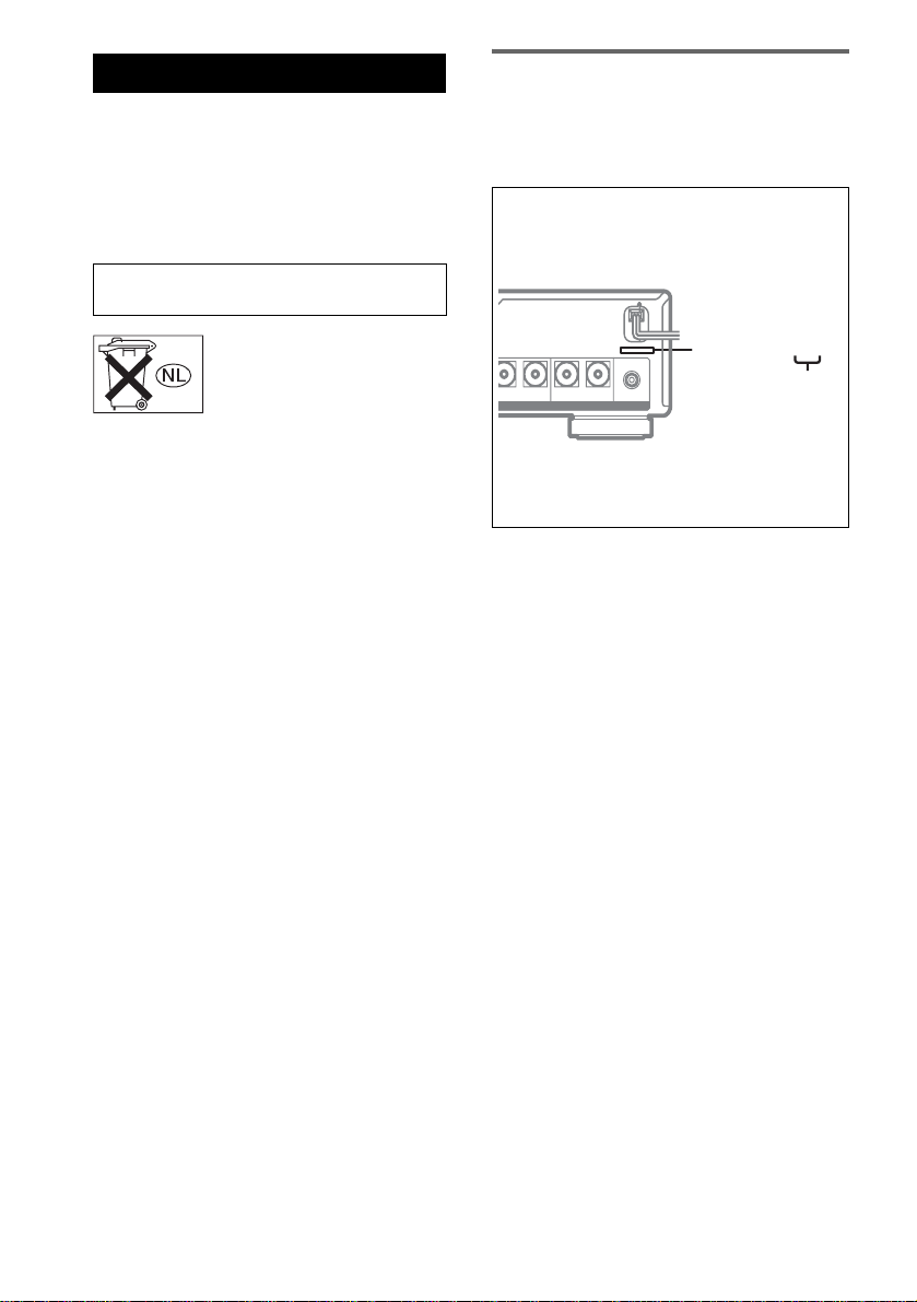
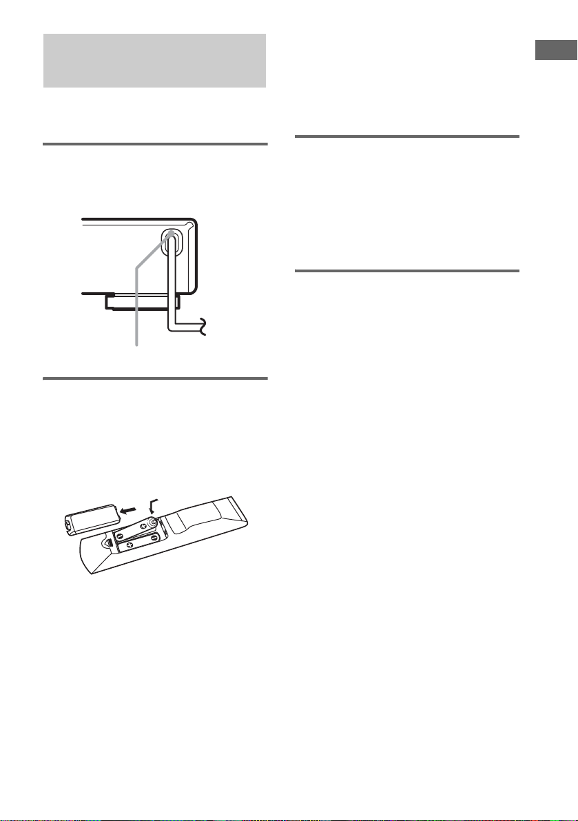
About area codes
The area code of the receiver you purchased is
shown on the right portion of the rear panel (see the
illustration below).
Don’t throw away batter ie s w ith
general house waste; dispose of
them correctly as chemical waste.
4-XXX-XXX-XX AA
Area code
+
FRONT R+–FRONT L
AUDIO
OUT
SUB WOOFER
Any differences in op eration, according to t he area
code, are clearly ind icated in the text, for example,
“Models of area code AA only”.
This receiver incorporates Dolby* Digital and Pro
Logic Surround and the DTS** Digital Surro und
System.
* Manufactured under license from Dolby
Laboratories.
“Dolby”, “Pro Logic” and the double-D symbol are
trademarks of Dolby Laboratories.
**Manufactured under license from Digital Theater
Systems, Inc.
“DTS”, “DTS-ES Extended Surround” and “Neo:6”
are trademarks of Digital Theater Systems, Inc.
GB
2
Page 3

Table of Contents
Hooking up Components
Required cords................... .... .................4
Connecting analog components..............5
Connecting digital components...............6
Connecting the antennas .........................7
Placing speakers...................................... 8
Connecting speakers...............................9
Before performing the initial setup.......11
Setting up and adjusting t he speakers...12
Adjusting the speaker levels and
balance............................................15
— TEST TONE
Checking the connections.....................16
Basic Operations
Selecting a component..........................17
Enjoying multichannel audio................17
Receiving broadcasts............................18
Using the Radio Data System (RDS)....20
(Models of area code CEK, CEL
only)
Changing information in the displ ay.... .21
About the indications in the display...... 22
Enjoying Surround Sound
Using only the front speakers ...............23
Enjoying higher fidelity sound..............23
Selecting a sound field..........................24
Customizing sound fields......................26
Using the supplied remote
Parts description...................................32
Table of buttons used to co ntrol each
component......................................36
Programming the remote......................38
Selecting the mode of the remote......... 41
Additional Information
Precautions............................................42
Troubleshooting....................................43
Specifications........................................45
List of button locations and reference
pages...............................................47
Index.....................................................49
Other Operations/Settings
Switching the audio input mode for
DVD playback................................ 28
Selecting the digital audio input
decoding priority.............................28
Selecting a bilingual play mode (Dual
Mono) .............................................29
Using the Sleep Timer ..........................29
Selecting a DTS 96/24 decoding
mode ...............................................30
Selecting a surround back decoding
mode ...............................................30
GB
3
Page 4
Hooking up Components
Required cords
Before you get started
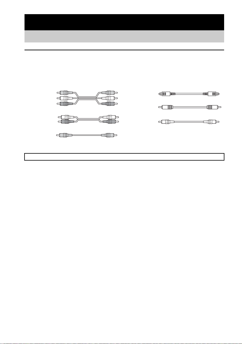
The hookup diagrams in this chapter assume the use of the following optional connection cords ((a) to
(f), not supplied).
(a) Audio/video cord
Yellow (video)
White (L/audio)
Red (R/audio)
(d) Optical digital cord
(e) Coaxial digital cord
(b) Audio cord
White (L)
Red (R)
(c) Video cord
Yellow
Notes
Turn off the power to all components befor e m aking a ny co nne ct ions.
• Be sure to make connections firml y to avoid humming and noise.
• When connecting an audio/video cord, be sure to match the color-coded pins to th e appr opr ia te ja c k on the
components: yellow (video) to ye llow; white (left, audio) to white; and red (right, audi o) to red.
• When connecting optical digit al cords, insert the cord plugs in straight unti l the y c lick into place.
• Do not bend or tie optical digita l cords.
(f) Monaural audio cord
Black
Tip
The audio cord (b) can be split into two monaural
audio cords (f).
GB
4
Page 5
Connecting analog components
If you connect your TV t o t he MONITOR jack, you can watch video image s f ro m the selected input
source (page 17) .
For detail s on the required cords ( (a) to (f)), see page 4.
Hooking up Components
COAXIAL
HDD/MD
DVD player
FRONT
L
R
MULTI CH OUT
SURROUND
CENTER
SUB
WOOFER
VIDEO OUT
L
AUDIO OUT
R
OUTPUT
VIDEO OUT
L
AUDIO OUT
R
OUTPUT
(a)
(a)
(a)
(b) (f)
(b)
AM
FM
U
75Ω
IN
IN
IN
OUT
DVDINDVD
TV/SAT
HDD/MD
DIGITAL SPEAKERS IMPEDANCE USE 4-16 Ω
FRONT
L
R
MULTI CH IN
COAXIALOPTICAL
(a)
SURROUND CENTER
ANALOGANTENNA
DVD DVDTV/SATVIDEO VIDEO
L
R
SUB WOOFER
IN IN
SURROUND BACK+–SURROUND R+–SURROUND L
MONITOR
+–
VIDEO
INININOUT
**
To the ANALOG VIDEO
IN L/R jacks
(a)**
TV monitor
L
R
AUDIO OUT
OUTPUT
(c)
MONITOR IN
INPUT
(c)
Satellite tuner*
VIDEO OUT
OUTPUT
VCR
CENTER
+–
–
FRONT R
* Use digital connections for audio signals. Connect the digital output jack of your satellite tuner to this
system’s TV/SAT OPT IN jack (see page 6 ).
**If you have the sound of the DVD player, VCR or satellite tuner going through the TV monitor, connect
the analog audio output jacks of the TV monitor to the ANALOG VIDEO IN L/R jacks. The sound of the
DVD player, VCR or satellite tuner will output to the speakers connected to the receiver.
GB
5
Page 6
.
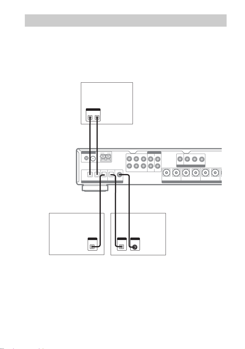
Connecting digital components
Connect the digital output ja cks of your DVD player (etc.) to th is system’s digital input jacks to bring
the multichannel surround s ound o f a movie th eater into your home. This receiver allows you to use a
speaker system with up to 6.1 channels. To fully enjoy multichannel surround sound, five speakers (two
front speakers, two surround speakers, and a center speaker) and a subwoofe r ar e required.
You can enjoy high fidelity reproduction of DVD software reco rded in the Dolby Digita l EX or D TSES format if you connect one additional surround back sp eaker (for a total of 6.1 channels).
For details on the required cords ((a) to (f)), see page 4.
MD deck, Hard disc
DIGITAL
OPTICAL
OUT
IN
(d) (d)
l
l
IN
OUT
ANALOGANTENNA
DVD DVDTV/SATVIDEO VIDEO
L
R
SUB WOOFER
IN IN
SURROUND BACK+–SURROUND R+–SURROUND L
DVD player
MONITOR
+–
VIDEO
INININOUT
Satellite tuner
AM
FM
U
COAXIAL
75Ω
COAXIALOPTICAL
IN
IN
OUT
HDD/MD
DIGITAL
OPTICAL
OUT
DVDINDVD
TV/SATINHDD/MD
DIGITAL SPEAKERS
(d)
*
(d)
DIGITAL
OPTICAL
OUT
SURROUND CENTER
FRONT
L
R
MULTI CH IN
*
(e)
DIGITAL
COAXIAL
OUT
* Connect this cord to either the COAX IN or the OPT IN jack. We recommend making connections to the COAX
IN jack.
Notes
• All of the digital audio jacks are compa tible with 32 kHz, 44.1 kHz, 48 kHz and 96 kHz sampling frequencies.
• To play back multichannel surround sound through this receiver, you may have to change the digital output setting
on the connected component. For details, refer to the operating instruc tions for the connected component .
GB
6
Page 7
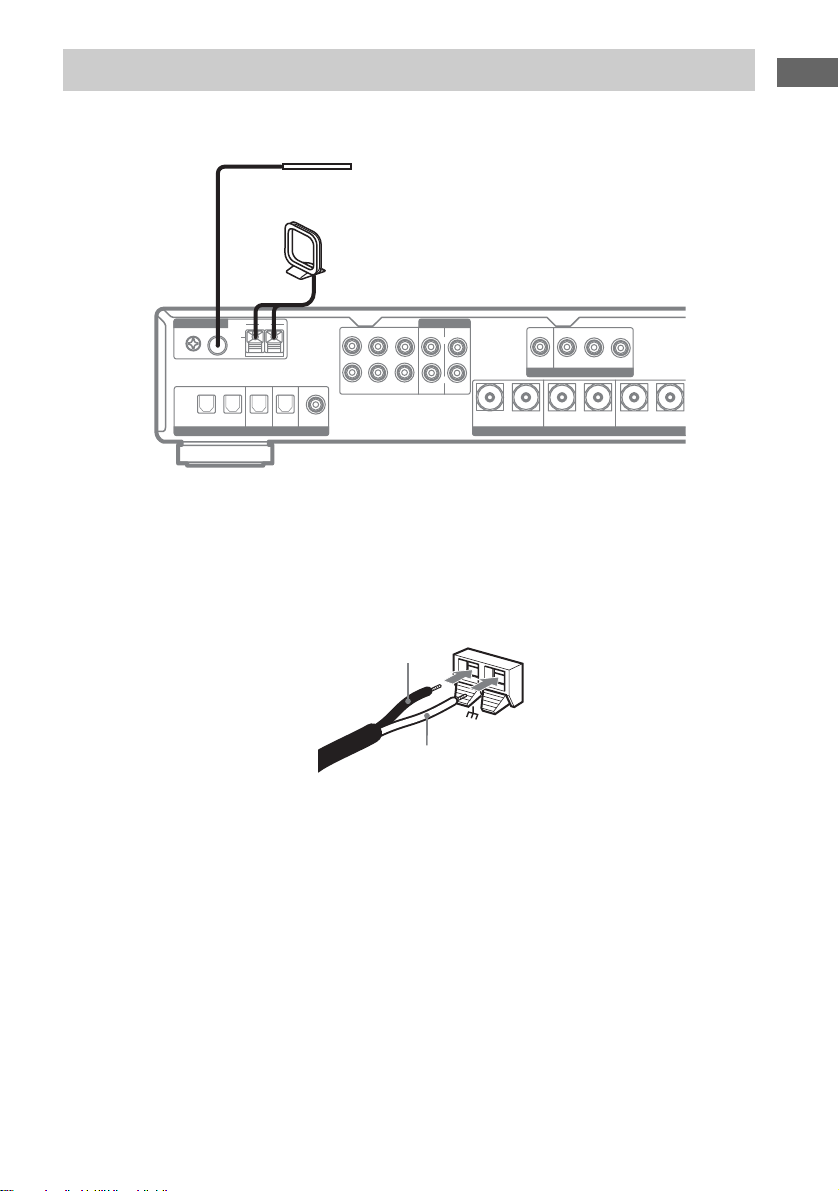
Connecting the antennas
S
Connect the supplied AM loop antenna and FM wire antenna as shown below.
FM wire antenna
(supplied)
AM loop antenna
(supplied)
Hooking up Components
ANALOGANTENNA
DVD DVDTV/SATVIDEO VIDEO
L
R
SUB WOOFER
IN IN
MONITOR
+–
SURROUND BACK+–SURROUND R+–SURROUND L
VIDEO
INININOUT
COAXIAL
HDD/MD
AM
FM
U
75Ω
IN
IN
IN
OUT
DVDINDVD
TV/SAT
HDD/MD
DIGITAL SPEAKER
FRONT
SURROUND CENTER
L
R
MULTI CH IN
COAXIALOPTICAL
Notes
• To prevent noise pickup, keep the AM loop antenna away from the receiver and other components.
• Be sure to fully extend the FM wire an ten n a.
• After connecting the FM wire ante nna, keep it as horizontal as possi ble .
• When you connect the supplied AM loop antenna, connect the black cord (A) to the
U terminal, and the whit e cord
(B) to the other terminal.
A
AM
B
GB
7
Page 8
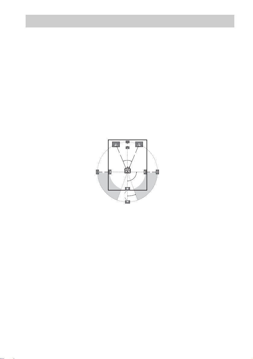
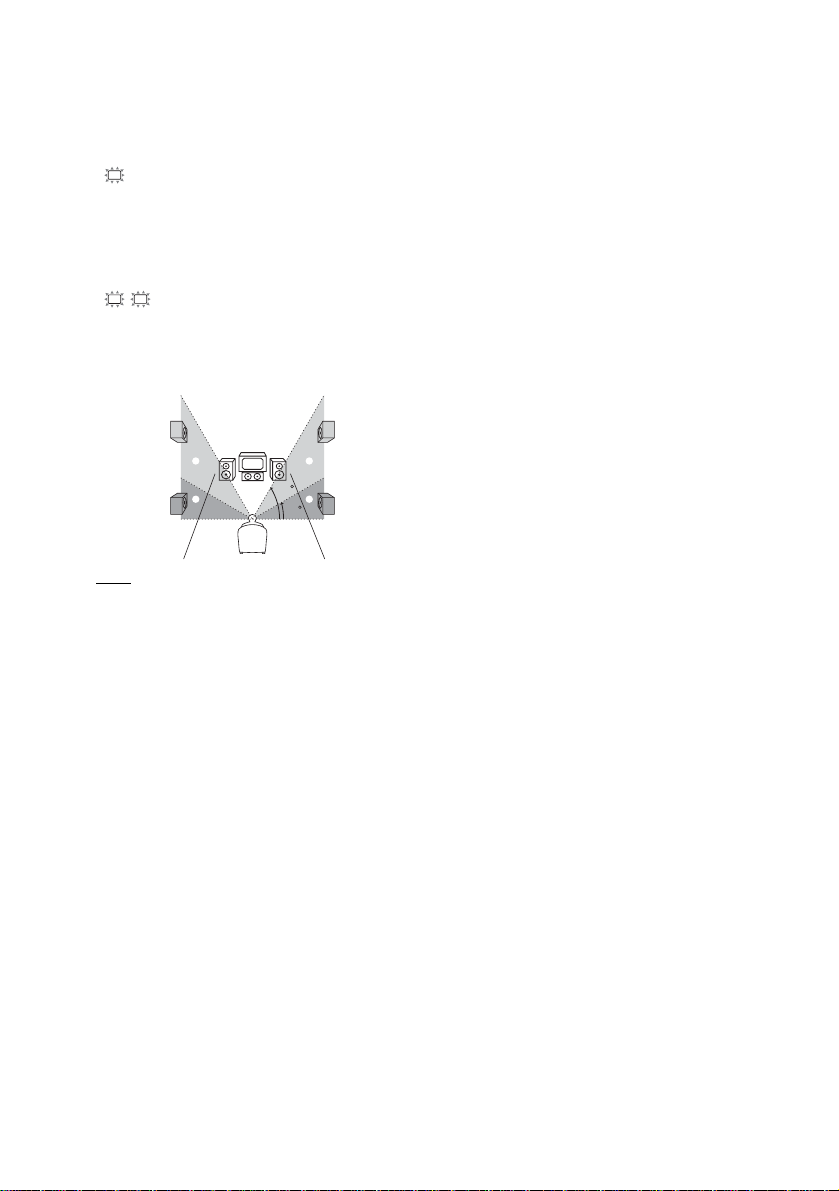
Placing speakers
To fully enjoy surround sound, configure your speakers as f ollows.
• Place the front speakers in a location 1 to 7 meters from the listening position (A).
• You can enjoy improved sound effects if you place the center spe aker from a distance eq ual to the
front speaker distance (A) to a distance 1.5 meters closer to your listening position (B).
• You can enjoy impr oved sound effects if yo u place the surround speakers from a dis t ance equal to
front speaker distance (A) to a distance 4.5 meters closer to your listening position (C).
• You can enjoy improved sound effects if you place the surround back speakers from a distance equal
to the front speaker distance (A) to a distance 4.5 meters closer to your listening position (D).
• You can place the surround speakers either behind you or to the si de of your listening posit i on,
depending on the shape of your room (etc.).
• You can place one su rr ound back speaker immediately behind t he listening position.
• Place the subwoofer at the same distance from the listening position as the front speakers (left or
right).
Place the speakers as illustrated below.
B
A A
45
CC
90
D
20
Note
Do not place the center speaker and surroun d speakers farther away from the listening pos ition than the front
speakers.
GB
8
Page 9
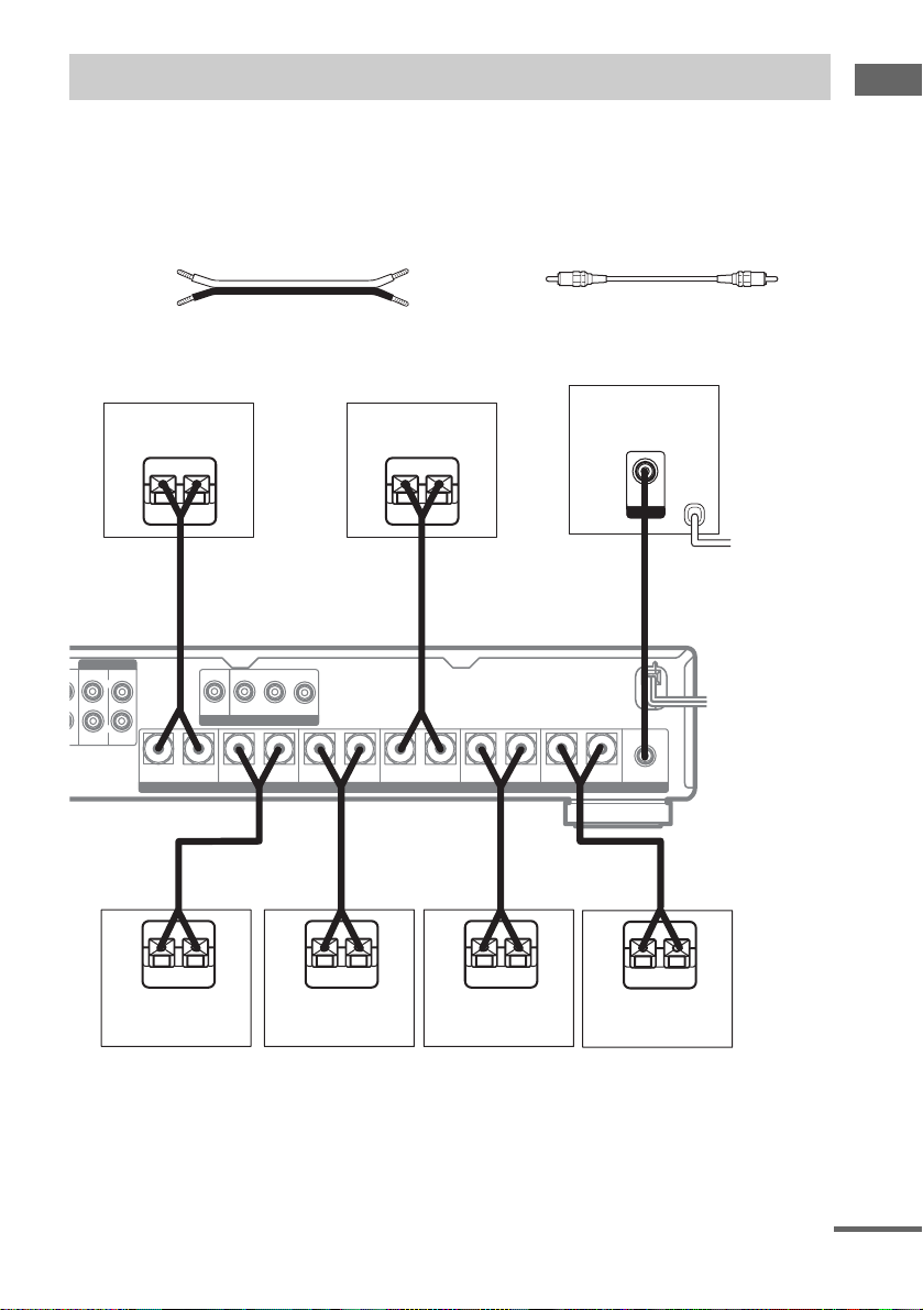
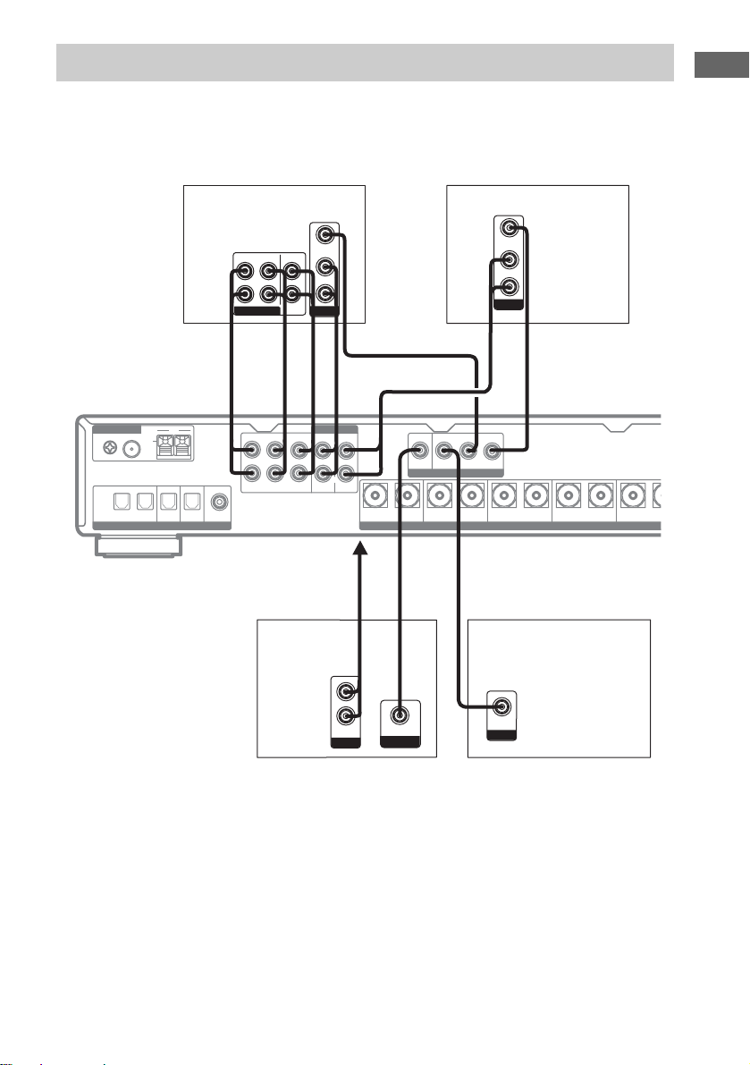
Connecting speakers
When connect in g speaker cords, make sure to atta ch the supplied spe aker plugs to the sp eaker cords.
For details on how to attach the speaker plugs , see the supplied flysheet.
speaker cords, be sure to turn off the receiver.
Required cords
(a) Speaker cords (not supplied)
( + )
( – )
(b) Monaural audio cord (not supplied)
Black
Before connecting the
Hooking up Components
Surround back
speaker
Ee
(a) (a)
ANALOG
R
DVD DVDTV/SATVIDEO VIDEO
L
R
ER
IN IN
E
Surround speaker
MONITOR
VIDEO
+–
SURROUND BACK+–SURROUND R+–SURROUND L
(a)
e
(R)
Center speaker
INININOUT
SPEAKERS
(a)
E
Surround speaker
(L)
Ee
+–
CENTER
IMPEDANCE USE 4-16 Ω
e
FRONT R
(a)
E
Front speaker
(R)
Subwoofer
AUDIO
IN
INPUT
(b)
To a wall outlet
b
(Switch the power
(POWER) to off before
connecting the power
cord.)
AUDIO
OUT
+–
FRONT L
e
E
+–
SUB WOOFER
(a)
e
Front speaker
(L)
continued
GB
9
Page 10
Note for connecting the
speaker cords to the receiver
If the speaker cords ar e no t prop erl y conn e cted ,
the receiver m ay be fatally damaged.
To avoid the possibility of damage, follow the
instructions below.
1 Do not hook up the speaker cords while the
receiver power is turned on.
Be sure to turn off the power first. After
turning off the power, it is recommend ed tha t
you disconnect the power cord for greater
safety.
2 Do not al l o w t he stripped end of a spea ker
cord to come into conta ct wi th any part of t he
rear panel or the a dj acent speaker term inal.
Before inserting a stripped sp eaker cord in to a
speaker terminal, twist the wires tightly
together to prevent contact between any
single strand from the cord and the rear panel
or the adjacent speaker terminal on the
receiver.
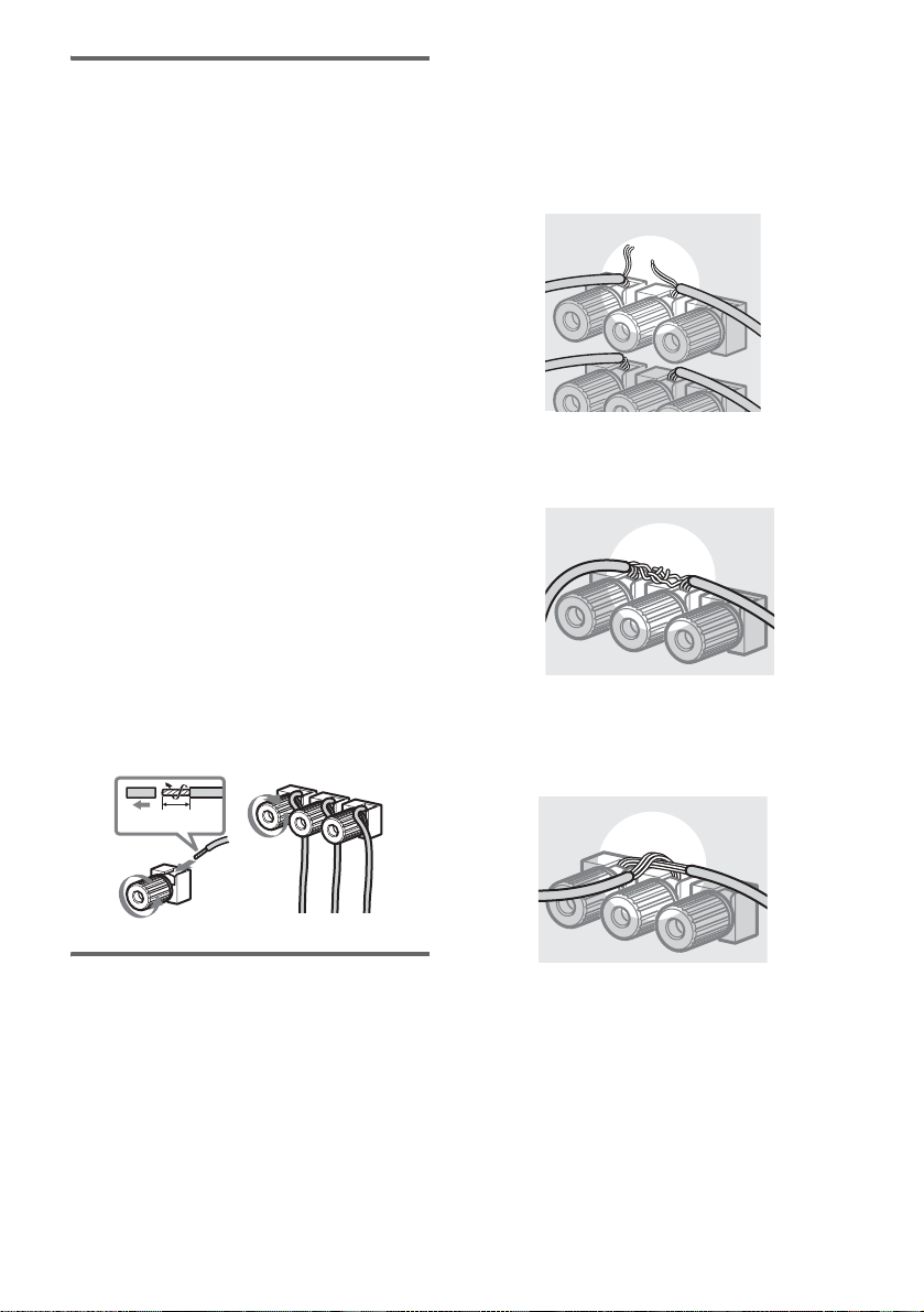
Remove about 10 mm of insulatio n at the end of
the cord, then twist the exposed wires.
Connect the stripped ends of the co rds to the
terminals, taki ng care to avoid contact between
the cords.
Make sure the cords are firmly connected to the
speaker and recei ver terminals.
Examples of poor speaker cord
connections
Stripped cords are not fully
attached and are touching the rear
panel of the receiver.
Stripped speaker cord is touching
another speaker terminal.
Stripped cords are touching each
other due to excessive removal of
insulation
10 mm
To avoid short-circuiting the
speakers
Short-circuiting of the speake rs may damage the
receiver. To prevent this , be sure to follo w these
precautions when connecting the speakers.
Make sure the bare wire of each sp eaker cord
does not touch another speaker terminal or the
bare wire of anothe r speaker cord.
GB
10
Page 11
Before performing the initial setup
Before performing the initial setup procedure,
be sure to perform the following operations.
• When not using the remot e for an exte nde d pe r iod
of time, remove the batterie s to a void possible
damage from battery leakage and corrosion.
• Turn off the power to all components before making
any connections.
• Be sure to make connec tions firmly to avoid
humming and noise.
Hooking up Components
Connecting the AC power
cord
Connect the AC power cord to a wall outlet.
b
AC power cord
Before you use your remote
Inserting batteries into the
remote
Insert two R6 (size AA) batteries wit h the
polarity (+ and –) pr operly oriented in the
battery compartment.
To a wall outlet
About the remote operation
• The instructions in this manual are described
using the controls on the remote. You may
also use the controls on the re ceiver i f they ar e
of the same or similar name as those on the
remote.
• The initial settings are underlined.
Performing initial setup
operations
Before using the receiver for the first time,
perform the initialization procedure as follows.
This procedure can also be used to re tu rn
settings you have m ade to their factory defa ul ts .
Press ?/1 while pressing 2CH. When
“CONFIRM” appears, press 2CH again.
The following items are reset or cleared:
• All sound field parameters
• All parameters in the SET UP, LEVEL and
TONE menus
• Sound fields memorized for each program
source
•Preset stations
Further, the master volume is set to the
minimum value.
Tip
Under normal conditions, the batteries should last for
about 6 months. When the remote no longer operates
the control center, replace both batteries with new
ones.
Notes
• Do not leav e th e r e mote in an extremely hot or
humid place.
• Do not use a new batter y with an old one.
• Do not expose the remote sensor of the control
center to direct sunlight or li ght ing a ppa r at use s.
Doing so may cause a malfunction.
11
GB
Page 12

Setting up and adjusting the speakers
You can perform setup and adjustme nt of t he
speakers connected to the rece iver by foll owing
the procedu res below.
1 Select the speaker impedance.
For more information, see “Setting up the
speaker impedance” (page 12).
2 Select the speaker size and distance.
For more information, see “Setting up the
speaker size and di stance” (page 12) .
3 Adjust the speaker level.
For more information, see “Adjusting the
speaker levels an d balance” (page 15) .
4 Check the connections of the
connected component.
For more information, see “Checking the
connections” (page 16).
Setting up the speaker
impedance
Set up the impedance value in the SET UP menu
depending on the speakers you connec te d.
The initial setting is 8 ohms.
1 Press ?/1 to turn on the system.
2 Press MAIN MENU repeatedly to select
“<SET UP>”.
3 Press F/f repeatedly to select “SP
IMP”.
4 Use G/g to select “4” or “8” according
to the impedance value of the
connected speakers.
Speaker impedance
To enjoy the best possible multi channel
surround, connec t speakers with a nominal
impedance of 8 ohms or higher to the FRONT,
CENTER, SURROUND and SURROUND
BACK terminals, and set the speake r impedance
to “8” in the SET UP menu. Refer to the
operating instructions supplied with your
speakers if you are not sure of their impedance.
(This information is often on the back of the
speaker.)
Alternatively, you may connect speakers with
nominal impedances between 4 and 8 ohms to
any or all of the speaker terminals. However, be
sure to set the speaker impedance to “4” in the
SET UP menu, if you connect even one speaker
with a nominal impedance between 4 and 8
ohms.
Setting up the speaker size
and distance
Use the SET UP menu to set the size and
distance of the sp eakers connected to the
receiver. You can select “EASY” (automatic) or
“NORM.” (manual) for the speaker size and
distance settings.
The initial setting is “EASY”.
1 Press ?/1 to turn on the system.
2 Press MAIN MENU repeatedly to select
“<SET UP>”.
3 Press F/f repeatedly to select “XXXX
SET”.
4 Use G/g to select “EASY” or “NORM.”.
•EASY
Selecting “EASY” allows you to set up yo ur
speakers automatically by selecting a predefined speaker pattern. Check your s peaker
pattern and perfor m speaker setup, referring
to the supplied “Installation Guide”.
• NORM.
Selecting “NORM.” allows you to adjust the
settings of each speaker manually. You can
set up the size or the distance of each speaker
in the SET UP menu. For more information,
see “Speaker setup parameters” below.
Speaker setup parameters
SW
x (SUB WOOFER) (Subwoofer)
•YES
If you connect a subwoofer, select “YE S”.
•NO
If you did not connect a subwoofer, select “NO”.
This activates the bass redirecti on circuitry and
outputs the LFE (Low Frequency Effect) signals
from other speakers.
12
GB
Page 13

When “NO” is selected, the front speakers are
automatically set to “LARGE”.
L
R
x (FRONT) (Front speakers)
• LARGE
If you connect large speakers that will effectively
reproduce bass frequencies, select “LARGE”.
Normally, select “LARGE”.
•SMALL
If sound seems distorted, or you feel a lack of
surround effects when using multichannel surround
sound, select “SMALL” to activate the bass
redirection circuitry and output the front channel
bass frequencies from the subwoofer. When the front
speakers are set to “SMALL”, th e cen ter and
surround speakers are a lso automatically set to
“SMALL” (unless previously set to “NO”).
C
x (CENTER) (Center speaker)
• LARGE
If you connect a large speaker that wil l effectively
reproduce bass frequencies, select “LARGE”.
Normally, select “LARGE”. However, if the front
speakers are set to “SMALL”, you cannot set the
center speaker to “LARGE”.
•SMALL
If sound seems distorted, or you feel a lack of
surround effects when using multichannel surround
sound, select “SMALL” to activate the bass
redirection circuitry and output the center channel
bass frequencies from the front speakers (if set to
“LARGE”) or subwoofer.
•NO
If you did not connect a center speaker, select “NO”.
The sound of the center channel will be output from
the front speakers.
SR
SL
x (SURROUND)
(Surround speakers)
• LARGE
If you connect large speakers that will effectively
reproduce bass frequencies, select “LARGE”.
Normally, select “LARGE”. However, if the front
speakers are set to “SMALL”, you cannot set the
surround speakers to “LARGE”.
•SMALL
If the sound is distorted, or you feel a lack of
surround effects when using multichannel surround
sound, select “SMALL” to activate the bass
redirection circuitry and output the surround channel
bass frequencies from the subwoofer or other
“LARGE” speakers.
•NO
If you did not connect surround speakers, select
“NO”.
If the surround speakers are set to “NO”, the
surround back speakers are automatically set to
“NO”.
SB
x (SURR BACK)
(Surround back speaker)
•YES
If you connect a surround back speaker, selec t
“YES”.
•NO
If you do not connect a surrou nd back speaker, sel ect
“NO”.
Tip
The “LARGE” and “SMALL” settings for each
speaker determine whether or not the inte r na l sound
processor will cut the bass signal from that channel.
When the bass is cut from a channel, the bass
redirection circuitry se nds the co rre sponding bass
frequencies to the subwoofer or othe r “LAR GE”
speakers. Howeve r, it is best not to cut them, if
possible. Therefore, even when using small speakers,
you can set speaker settings to “LARGE” if you want
to output the bass frequenc ie s f r o m that speaker. On
the other hand, if you are using a large speake r , but
prefer not to have bass frequencies output from that
speaker, set it to “ SMA L L”.
If the overall sound level is lower than you would
prefer, set all speakers to “LARGE”. If there is not
enough bass, you can use the equalize r to boost the
bass levels. To adjust the bass, see pa ge 27.
L
R
x DIST. XX m
(Front speaker distance)
Initial setting: 3.0 m
Lets you set the distance from your listening position
to the front speakers (A on page 8). You can adjust
from 1.0 m to 7.0 m in 0.1 meter steps.
If both front speakers are n ot p lac ed an eq ua l d i st an ce
from your listening position, set this distance to the
closest speaker.
C
x DIST. XX m
(Center speaker distance)
Initial setting: 3.0 m
Lets you set the distance from your listening position
to the center speaker. You can adju st from 1.0 m to 7.0
m in 0.1 meter ste ps .
SR
SL
x DIST. XX m
(Surround speaker distance)
Initial setting: 3.0 m
Hooking up Components
continued
13
GB
Page 14
Lets you set the distance from your listening position
to the surround speakers. You can adjust from 1.0 m to
7.0 m in 0.1 meter steps.
If both surround speakers are not placed an equal
distance from your listening position, set this distance
to the closest speaker.
SB
x DIST. XX m
(Surround back speaker distance)
Initial setting: 3.0 m
Lets you set the distance from your listening position
to the surround back speaker. You can adju st from 1.0
m to 7.0 m in 0.1 me ter steps.
SR
SL
x PL.
(Surround speaker placement)
*
Lets you specify the height of your surround speakers
for proper implementati on of sur ro und effects in the
Cinema Studio EX modes (page 24).
screen. If you cannot obtain a satisfact or y sur r ound
effect because the surround speaker s are too c los e,
setting the surround speaker distance closer (shorter)
than the actual distance will create a larger sound stage.
Adjusting these parameter while listening to the sound
often results in much better surr ound sound. Give it a
try!
B
A
B
60
A
30
•LOW
Select if the height of your surround speake r s
corresponds to section A.
•HIGH
Select if the height of your surround speake r s
corresponds to section B.
* This se tup item is not available when the surro und
speaker paramet er is set to “NO”.
Tip
The receiver lets you input speake r positions in terms
of distance. However, it is not poss ibl e to se t the
distance of the center speaker further than the front
speakers. Also, the center speaker cannot be set more
that 1.5 m closer than the front speakers.
Likewise, the surround speakers cannot be set farther
away from the listen ing position than the front
speakers, and can be no more than 4.5 me te r s cl ose r .
This is because incorrect speaker placement is not
conducive to the enjoyment of surround sound.
Please note that setting the speaker distance closer than
the actual location of the speakers will cause a delay in
the output of sound from that speaker. In other words,
the speaker will sound like it is farther away.
For example, setting the cent e r speaker distance 1–2
meters closer than the actual speaker position will
create a fairly real istic sensation of being “ins ide ” the
14
GB
Page 15

Adjusting the speaker levels and balance
— TEST TONE
Use the remote while seated in your listening
position to adjust the level of each speaker.
1 Press ?/1 to turn on the receiver.
2 Press TEST TONE.
“T.TONE” appe ars i n the d ispl ay an d a tes t
tone is output from each speaker in th e
following sequ ence:
r
Front (left)
r
Center
r
Front (right)
r
Surround (right)
r
Surround (back)
r
Surround (left)
r
Subwoofer
Notes
• The front balance, center level, surround level,
surround back level and subwoofer level are shown
in the display during adjustme nt.
• To enjoy better sound quality, do not turn up the
volume of the subwoofer too high .
Hooking up Components
3 Adjust the LEVEL parameters so that
the level of the test tone from each
speaker sounds the same when you
are in your main listening position.
To adjust the balance and level of speakers,
press MAIN MENU repeatedly to select
LEVEL menu, then press F/f to select the
parameter you want to adjust (page 26).
Next, press G/g to select a setting.
4 Press TEST TONE again to turn off the
test tone.
Tip
You can adjust the level of all speakers at the same
time. Press MASTER VOL +/– on the remote or rotate
VOLUME on the receiver.
15
GB
Page 16

Checking the connections
After connecting all of your components to the
receiver, check that the connections were made
correctly as follows.
1 Press ?/1 to turn on the receiver.
2 Press the button for the component
(VIDEO, DVD, TV/SAT, HDD/MD, MULTI
CH) that you want to check.
Or rotate INPUT SELECTOR on the
receiver.
3 Turn on the component and start
playback.
4 Press MASTER VOL +/– to adjust the
volume.
Or rotate VOLUM E o n the receiver.
If you do not obtain nor mal sound output af te r
performing this procedure, see
“Troubleshooting” on page 43 and take the
appropriate measures to correct the pr oblem.
16
GB
Page 17

Basic Operations
Selecting a component
1 Press the button for the component
(VIDEO, DVD, TV/SAT, HDD/MD,
TUNER) that you want to enjoy.
Or rotate INPUT SELECTOR on the
receiver.
The selected input source appears in the
display.
To select the Display
VCR VIDEO
DVD player DVD
TV or Satellit e tu n e r TV/SAT
Hard disc or MD deck HDD/MD
Built-in tu ner TUNER
2 Tur n on the component and start
playback.
3 Press MASTER VOL +/– to adjust the
volume.
Or rotate VOLUME on the receiver.
To mute the sound
Press MUTING to mute the sound. “MUTING”
appears on the display when the sound is mu ted.
To cancel muting, press MUTING again or turn
up the volume.
Enjoying multichannel audio
You can select an audio source from th e
components connected to the MULTI CH IN
jacks of the receiver. This enables yo u to enj oy
high quality ana lo g output from sources l i ke
Super Audio CD.
Surround effects are not activated when using
this input method.
Press MULTI CH repeatedly to select
“MULTI CH IN”.
Basic Operations
17
GB
Page 18

Receiving broadcasts
Before receiv in g broadcasts, make sur e you
have connected the supplie d FM and AM
antennas to th e receiver (page 7) .
Automatic tuning
If you do not know the f requency of the station
you want, you can let th e receiver scan all
available st ations in your ar ea.
1 Press TUNER to select the FM or AM
band.
Or rotate INPUT SELECTOR on the
receiver to select “TUNER FM” or
“TUNER AM”.
2 Press TUNING MODE repeatedly to
select “AUTO T.”.
3 Press TUNING + or TUNING –.
Press TUNING + to scan from a low
frequency to a high one; press TUNING –
to scan from a high frequency to a low one.
The receiver stops scanning whenever a
station is received.
When the receiver reaches either end
of the band
Scanning is repeated in the same direction.
4 To continue scanning, press TUNING +
or TUNING – again.
Manual tuning
You can tune in the station in 50 kHz steps for
the FM band and 9 kHz steps for the AM band.
1 Press TUNER to select the FM or AM
band.
Or rotate INPUT SELECTOR on the
receiver to select “TUNER FM” or
“TUNER AM”.
2 Press TUNING MODE repeatedly to
select “MANUAL T.”.
3 Press TUNING + or TUNING –
repeatedly to tune in the station you
want.
Press TUNING + to change the frequency
from low to high.
Press TUNING – to change the frequency
from high to low.
Tip
If “STEREO” flashes in the displa y a nd FM ste r eo
reception is poor, press FM MODE to improve the
sound. In this case, the sound switches to monaural
reception and you will be unable to enjoy the effects of
stereo sound, but the overall sound will be less
distorted.
If the system is forced to go into monaural mode by
pressing FM MODE, “MONO” appears in the display.
Note
If “STEREO” does not appear at all when an FM
broadcast is received normally, pr es s FM MODE to
turn on the “STEREO” indication. If the FM reception
is weak, “STEREO” will not light up.
Preset tuning
You can pres et your favorit e FM or AM st ation s
to the receiver. T his enables you to tune in the
stations directly. Up to 30 FM or AM stations
can be preset, and the receiver will scan all of the
stations you have pre set.
Before tuning in preset stations, be sure to preset
them using the steps in “Presetting radio
stations”.
Presetting radio stations
1 Press TUNER to select FM or AM band.
Or rotate INPUT SELECTOR on the
receiver. The last received station is tuned
in.
2 Tune in the station that you want to
preset using Automatic tuning
(page 18) or Manual tuning (page 18).
3 Press MEMORY.
“MEMORY” appe ars in the display for a
few seconds.
Perform steps 4 t o 5 before “MEMOR Y ”
goes out.
Note
If the ALT key lights up during the above procedure ,
press ALT to turn it off (deactivate ALT).
18
GB
Page 19

4 Press SHIFT to select the memory page
and press PRESET/CH + or PRESET/
CH – to select a preset number.
If “MEMORY” go es out before you press
the preset number, st art again from step 3.
5 Press MEMORY again to store the
station.
If “MEMORY” go es out before you can
store the station, st art again from step 3.
6 Repeat steps 2 to 5 to preset another
station.
Tuning to preset stations
1 Press TUNER to select the FM or AM
band.
Or rotate INPUT SELECTOR on the
receiver to selec t “TUNER FM” or
“TUNER AM”.
2 Press SHIFT repeatedly to select a
memory page (A, B, C).
3 Press the number button to select a
preset station you want.
The selected prese t s ta t ion in the current
memory page is tuned in. Press SHIFT to change
the memory page.
Example 2: AM 1,350 kHz
bbb
1 3 50
You do not have to enter the last “0” when
the tuning step is set to 100 kHz for FM, and
10 kHz for AM.
If you cannot tune in a station
and the entered numbers flash
Make sure you’ve entered the right frequency. If
not, repeat step 3. If the entered numbers still
flash, the frequency is not used in your ar ea.
Basic Operations
Direct tuning
You can tune in a station by selecting the
frequency directly with the number buttons.
1 Press TUNER to select the FM or AM
band.
Or rotate INPUT SELECTOR on the
receiver to selec t “TUNER FM” or
“TUNER AM”.
2 Press D.TUNING.
The cursor blinks on the first digit of the
frequency.
3 Press the number buttons to enter the
frequency you want.
Example 1: FM 102.50 MHz
bbbb
1 0 2 50
19
GB
Page 20

Using the Radio Data System (RDS)
(Models of area code CEK, CEL only)
RDS enables radio stations to send additional
information along with regular program signals.
This receiver also allows you to use RDS (Radio
Data System) and display RDS information.
Receiving RDS broadcasts
Simply select a station on the FM band.
Use “Automatic tuning” (page 18), “Manual
tuning” (page 18), or “Preset tuning” (page 18)
or “Direct tuning” (page 19).
When you tune in a stat i on t hat provides RDS
data services, the RDS indicator lights up and
the program station name appears in the display.
Note
RDS may not work properly if the station you tuned to
is not transmitting the RDS signal properly or if the
signal strength is weak.
Displaying RDS information
While receiving an RDS station, press
DISPLAY.
Each time you press the button, RDS
information on the display changes cyclically as
follows:
PS (Program Se rvice name) or prese t s ta t ion
namea) t Frequencyb) t PTY (Program
Type) indication
indication
(in 24-hour system ) t Sound field currently
applied t Volume level
a)
This information appears only when PS da ta is
received or the preset station is indexed.
b)
This information also appears for non- R DS FM
stations.
c)
Type of program being broadcast (see page 20).
d)
Text messages sent by the RDS station.
Notes
• If there is an emergency announcement by
government authoritie s, “ALARM” flashes in the
display.
c)
t RT (Radi o T ext)
d)
t CT (Current Time) indication
• If the message consists of 9 chara cters or more, the
message scrolls across th e di s p lay .
• If a station does not provide a particular RDS service,
“NO XXXX” (such as “NO TEXT”) appears in the
display.
Description of program types
Program type
indication
NEWS News programs
AFFAIRS Topical programs that expand on
INFO Programs offering information on
SPORT Sports prog rams
EDUCATE Educational programs, such as
DRAMA Radio plays and serials
CULTURE Programs about national or
SCIENCE Programs about the natural
VARIED Other types of programs suc h as
POP M Popular music programs
ROCK M Rock music programs
EASY M Easy listening
LIGHT M Instrumental, vocal, and choral
CLASSICS Performances of major orchestras,
OTHER M Music that does not fit into any of
WEATHER Weather information
FINANCE Stock market reports and trading,
CHILDREN Programs for children
SOCIAL Programs about people and the
RELIGION Programs of religious content
PHONE IN Programs where members of the
Description
current news
a wide spectrum of subjects,
including consumer affairs and
medical advice
“how-to” and advice programs
regional culture, such as language
and social concerns
sciences and technology
celebrity interviews, panel games,
and comedy
music
chamber music, opera, etc.
the above categories, suc h as
Rhythm & Blues and Reggae
etc.
things that affect them
public express their views via
phone or public forum
20
GB
Page 21

Program type
indication
TRAVEL Programs about travel. Not for
LEISURE Programs on recreational
JAZZ Jazz programs
COUNTRY Country music programs
NATION M Programs featuring the popular
OLDIES Programs feat uring oldies music
FOLK M Folk music programs
DOCUMENT Investigative features
NONE Any programs not defined above
Description
announcements that are located by
TP/TA.
activities such as gardening,
fishing, cooking, etc.
music of the country or region
Changing information in the display
You can check the currently used sound field
etc. by changing the information shown in the
display.
Press DISPLAY repeatedly.
Each time you press DISPLAY, the display
changes as follows.
• When signals are output from a component
other than a tune r:
Input name t Sound fi el d na me t Vol um e
level
• When “TUNER FM” or “TUNER AM” is
selected:
Frequency t Sound field name t Volume
level
• When an RDS station is received:
See “Displaying RDS information” on
page 20.
Basic Operations
21
GB
Page 22

About the indications in the display
12 34 5
9
78
6
PL II
;
MPEG-2 AAC
OPT COAX
qs
SLEEP
LFE
LCR
SLSW
SSB
SR
or
SSB
DIGITAL EX
;
DTS-ES
NEO:6
qa
0
A SLEEP: Lights up when the sleep timer is
activated.
B Playback channel indicators: The letters
(L, C, R, etc.) indicate the channel(s ) being
played back. The boxes around the letters vary
to show how the receiver downmixes the
source sound (based on the speakers settings).
Abbreviations: L (Front Left), R (Front Right),
C (Center (monaural)), SL (Surr ound Left),
SR (Surround Right), S (Surround (monaural
or the surround components obtained by Pro
Logic processing)), SB (Surroun d Ba ck), SW
(subwoofer)
Example:
Recording format (Front/Sur r ound): 3/2
Output channel: Surround and surrou nd back
speakers absent
Sound Field: A.F.D. (Auto Format Direct) AUTO
LCR
SW
SSB
SL SR
C ; DIGITAL EX: Lig hts up when the r eceiver
is decoding signals recorde d in t he D olby
Digital format.
D ; PL (II): “PL” lights up when a 2-channel
signal is applied with “DOLBY PL” or
C.ST.EX A–C. “PL II” lights up when Dolby
Pro Logic II processing (“P LII MOV” or
“PLII MUS”) is applied. However, this
indicator does not light if th e cen ter and
surround speakers are set to “NO”.
D.RANGE
STEREO MONO
MEMORY
EQ
RDS
E D.RANGE: Lights up when dynamic range
compression is activated (page 26).
F EQ: Lights up when the equalizer is activated.
G Tuner indicators: Lights up when using the
receiver to tune in radio stations, etc. See
pages 18–20 for tuner operations.
H COAX: Lights up when the source signal is a
digital signal being input th rough the COAX
IN jack.
I OPT: Lights up when the source signal is a
digital signal being input through the OPT IN
jack.
J NEO:6: Lights up when DTS Neo:6 Cinema/
Music mode decoding is acti va te d.
K DTS-ES: Lights up when DTS-ES signals are
being input.
L : Lights up when the disc being played
LFE
back contains the LFE channel, and the LFE
channel signal is ac tu ally being reproduced.
GB
22
Page 23

Enjoying Surround Sound
Using only the front speakers
In this mode, the receiver outputs sound from
the front L/R speakers only. No sound is output
from the subw oofer.
Listening to 2 channel stereo
sources (2CH STEREO)
Standard 2 channel stereo sources completely
bypass soun d fiel d proc essi ng and mu lti channe l
surround formats are downmixed to 2 channel.
Press 2CH.
Or press SOUND FIELD on the receiver
repeatedly.
“2CH ST.” appears in the display and the
receiver switches to the 2CH STEREO mode.
Note
No sound is output from the subwoofer in the 2CH
STEREO mode. To listen to 2 channel ster e o sour c es
using the front L/R speakers and a subw oof e r, se t to
“A.F.D. AUTO”.
Listening to sound without
any adjustment (DIRECT)
You can listen to sound without adjusting the
equalizer or sound field effects.
Press DIRECT.
“DIRECT” appears in the display, and the
equalizer and sound field effects are cancelled.
Enjoying higher fidelity sound
The A.F.D. (Auto Format Direct) mode allows
you to select the decoding mode you want for
your audio soun d.
A.F.D. mode
(Display)
A.F.D. AUTO
(A.F.D. AUTO)
DOLBY PRO LOGIC
(DOLBY PL)
DOLBY PL II MOVIE
(PLII MOV)
DOLBY PL II MUSIC
(PLII MUS)
Neo:6 Cinema
(NEO6 CIN)
Neo:6 Music
(NEO6 MUS)
Decoding input audio signals
automatically
In this mode, the receiver automatically detects
the type of audio sig nal being input (Dolby
Digital, DTS, standard 2 channel stereo, etc.)
and performs the proper decoding if ne cessary.
This mode presents the sound a s it was recorded/
encoded, without adding any surround ef fects.
However, if ther e ar e no low frequency si gn als
(Dolby Digital LFE, etc.) it will generate a low
frequency signal for output to the subwoofer.
Press A.F.D. repeatedly to select “A.F.D.
AUTO”.
Or press SOUND FI ELD on the receiver
repeatedly.
The receiver automatically detects the type of
audio signal being input an d performs th e proper
decoding if necessary.
Decoding mode
As encoded
Dolby Pro Logic
Dolby Pro Logic II
DTS Neo:6
Enjoying Surround Sound
continued
23
GB
Page 24

Enjoying stereo sound in
multichannel (2 channel
decoding mode)
This mode lets you specify the type of decoding
used for 2 channel audio sources. Th is receiver
can reproduce 2 channel sound in 6 channe ls
through DTS Neo:6 ; 5 channels through Dolby
Pro Logic II or 4 channel s through Dolby Pro
Logic.
However, DTS 2CH sources are not decoded by
DTS Neo:6; thes e so urces are output in 2
channels.
Press A.F.D. repeatedly to select the 2
channel decoding mode.
Or press SOUND FIELD on the system
repeatedly.
x DOLBY PRO LOGIC (DOLBY PL)
Performs Dolby Pro Logic decoding. Sources recorded
in 2 channel format are decoded into 4.1 c ha nne ls.
x DOLBY PL II MOVIE (PLII MOV)
Performs Dolby Pro Logic II Movie mode dec oding.
This setting is ideal f or mo vies encoded in Dolby
Surround. In addition, this mode can reproduc e sou nd
in 5.1 channel format when watching videos of
overdubbed or old movies.
x DOLBY PL II MUSIC (PLII MUS)
Performs Dolby Pro Logic II Music mode decoding.
This setting is ideal f or n or mal stereo sources such as
CDs.
x Neo:6 Cinema (NEO6 CIN)
Performs DTS Neo:6 Cinema mode decoding.
x Neo:6 Music (NEO6 MUS)
Performs DTS Neo:6 Music mode decoding. This
setting is ideal for normal stereo sources such as CDs.
If you connect a subwoofer
When the audio signal is 2 channel stereo or if
the source signal does not include an LFE signal,
the receiver generates a low frequency signal for
output to the subwoofer. However, the low
frequency signal i s not output when “Neo:6
Cinema” or “Neo:6 Music” is selected.
Selecting a sound field
You can take advant age of surround sou nd
simply by selecting one of the receiver’s preprogrammed so und fields. They br i ng the
exciting and powerful sound of movie theaters
and concert halls in to your home.
Selecting a sound field for
movies
Press MODE repeatedly to select the sound
field you want.
Or press SOUND FIELD on the system
repeatedly.
The selected sound field appears in the di splay.
Sound field Display
CINEMA STUDIO EX A DCS C.ST.EX A
CINEMA STUDIO EX B DCS C.ST.EX B
CINEMA STUDIO EX C DCS C.ST.EX C
About DCS
(Digital Cinema Sound)
Sound fields marked with DCS use DCS
technology. DCS is the concept name of the
surround technology for home theater developed
by Sony. DCS uses DSP (Digital Signal
Processor) technology to reprod uce the sound
characteristics of an actual cinema cutting studio
in Hollywood. When played at home, DCS will
create a powerfu l th eater effect that m imics the
artistic combinat i on of sound and action as
envisioned by the m ovie director.
x C.ST.EX A
(CINEMA STUDIO EX A
Reproduces the sound characterist ic s of the Sony
Pictures Entertainment “Cary Grant Theater” cinema
production studio. This is a standard mode, grea t fo r
watching most types of movies.
x C.ST.EX B
(CINEMA STUDIO EX B
Reproduces the sound characterist ic s of the Sony
Pictures Entertainment “Kim Novak The ater” cinema
production studio. This mode is ideal for wat ch ing
science-fiction or action mo vie s with lots of sound
effects.
DCS )
DCS )
24
GB
Page 25

x C.ST.EX C
(CINEMA STUDIO EX C
Reproduces the sound characte ristics of the Sony
Pictures Entertainment scoring stage. This mode is
ideal for watching musica ls or films where orchestra
music is featured in the soundtrack.
DCS )
About CINEMA STUDIO EX modes
CINEMA STUDIO EX modes are suitable for
watching motion picture DVDs (etc.), with
multichannel su r round effects. You can
reproduce the sound characteristics of Sony
Pictures Entertainment’ s dubbing studio in your
home.
The CINEMA STUDIO EX modes consist of
the following three elements.
• Virtual Multi Dimension
Creates 5 sets of virtual speakers from a single
pair of actual surround speakers.
• Screen Depth Matching
Creates the sensati on that th e sound is coming
from inside the sc reen like in theaters.
• Cinema Studio Reverberation
Reproduces the type of reverberation found in
theaters.
The CINEMA STUDIO EX modes integrate
these three elem ents simultaneo usl y.
Tips
• The receiver memorizes the last sound field selected
for each program source. Whenever you sele c t a
program source, the sound field that was last applied
is automaticall y applied again. For exam ple, if you
listen to DVD with HALL as the sound field, change
to a different program source, then return to DVD,
HALL will be applied again.
• You can identify the encoding format of DVD
software, etc. by looking at the logo on the pack ag e.
– : Dolby Digital discs
– : Dolby Surround encoded
programs
– : DTS Digital Surround encoded programs
Notes
• The effects provided by the virtual spea ke rs ma y
cause increased noise in the playback signal.
• When listening with sound fields that employ the
virtual speakers, you will not be able to hear any
sound coming directly from the sur r ound speakers.
Selecting a sound field for
music
Press MODE repeatedly to select the sound
field you wa nt.
Or press SOUN D FIELD on the system
repeatedly.
The selected sound field appears in the display.
Sound field Display
HALL HALL
JAZZ CLUB JAZZ
LIVE CONCERT CONCERT
x HALL (HALL)
Reproduces the acoustics of a cla ssical concert hall.
x JAZZ (JAZZ CLUB)
Reproduces the acoustics of a jazz club.
x CONCERT (LIVE CONCERT)
Reproduces the acoustics of a 300 -seat live house.
To turn off the surround effect
Press 2CH or A.F.D.
Enjoying Surround Sound
25
GB
Page 26

Customizing sound fields
By adjusting the LEVEL menu and TONE
menu, you can customize the sound fields to suit
your particular lis te ni ng situation.
Position your sp eakers and do the procedures
described in “Placing speakers” (page 8) and
“Checking the connections” (page 16) before
you customize a s ound field.
Adjusting the LEVEL menu
You can use the LEVEL menu to adjust the
balance and level of each speake r. These se ttings
are applied to all sound fields. (Except for the
EFCT. parameter. The setting of the EFCT.
parameter is st ored independent l y for each
sound field.)
1 Start playing a source encoded with
multichannel surround effects (DVD,
etc.).
2 Press MAIN MENU repeatedly to select
the LEVEL menu.
3 Press F/f to select the menu item.
For details, see “LEVEL menu p arameters”
below.
4 While monitoring the sound, press G/g
to adjust the selected parameter.
5 Repeat steps 3 and 4 to adjust other
parameters.
LEVEL menu parameters
L
R
x BAL. XXX (Front speaker balance)
Lets you adjust the balance between the front left and
right speakers.
• BALANCE (
• L (+1 dB to +8 dB)
• R (+1 dB to +8 dB)
±0 dB)
x CTR XXX dB (Center speaker level)
x SUR.L. XXX dB
(Surround speaker (L) level)
x SUR.R. XXX dB
(Surround speaker (R) level)
x SB XXXX dB
(Surround back speaker level)
x S.W. XXX dB (Subwoofer level)
The initial setting is 0 dB.
Lets you adjust the leve l of the speakers (center,
surround left, surround right, surround bac k) or
subwoofer.
You can adjust from –10 dB to +10 dB in 1 dB steps.
D.RANGE
x COMP.
(Dynamic range compressor)
Lets you compress the dynamic range of sound tracks.
This may be useful when you want to watch movies at
low volumes late at night.
•OFF
The dynamic range is not compressed.
•STD
The dynamic range is compressed as intended by the
recording engineer.
•MAX
The dynamic range is compressed dramatically.
Tip
The dynamic range compressor feat ur e let s you
compress the dynamic range of soun dtr a ck s bas ed on
the dynamic range information in cl ude d in the Dolby
Digital signal. “STD” is the initial setting, but this only
enacts light co mpression.
Therefore, we recommend using the “MAX” setting.
This greatly compresses the dynamic range and lets
you view movies late at night at low volumes. Unlike
analog limiters, the levels are predetermined and
provide a very natural-sounding compression.
Note
Dynamic range compression is possib le with Dol by
Digital sources only.
26
GB
Page 27

x EFCT. XXX (Effect level)
Lets you adjust the size of the curren t surround
effect. This men u i te m is displayed only when
“C.ST. EX A”, “C.ST. EX B”, “C.ST.EX C”,
“CONCERT”, “JAZZ”, or “HALL” is selected.
•STD
Normal surround effects are applied.
•MIN
Decreases the surround effect.
•MAX
Increases the surround effect.
Adjusting the TONE menu
You can use TONE menu to adjust the tonal
quality (bass and treble level) of the front
speakers.
1 Start playing a source encoded with a
variety of surround effects (DVD, etc.).
2 Press MAIN MENU repeatedly to select
the TONE menu.
3 Press F/f to select the menu item you
want.
For details, see “TONE menu parameters”
below.
4 While monitoring the sound, press G/g
to adjust the selected parameter.
5 Repeat steps 3 and 4 to adjust other
parameters.
Note
You cannot adjust the equalizer when the system is
decoding PCM 96 kHz signals, or when DTS 96/24,
DTS-ES Matrix or DTS Neo:6 decoding is applied.
TONE menu parameters
x BASS XXX dB
(Front speaker bass level)
x TREB. XXX dB
(Front speaker treble level)
The initial setting is 0 dB.
You can adjust from –6 dB to +6 dB in 1 dB steps.
Enjoying Surround Sound
27
GB
Page 28

Other Operations/Settings
Switching the audio input mode for DVD playback
You can switch th e audio input mode for D V D
playback.
1 Press DVD to select DVD input.
2 Press INPUT MODE repeatedly to
select the audio input mode.
The selected audi o in put mode appears in
the display.
Audio input modes
• AUTO IN
Gives priority to di gi t al audio signals, and
specifies analog au dio signals input to the
analog IN (L/R) jacks when no digit al audio
signal is present.
• COAX IN
Specifi e s digital a u d io signals input to the
digital COAX IN jack.
•OPT IN
Specifi e s digital a u d io signals input to the
digital OPT IN jacks.
• ANALOG
Specifies the analog audio signals input to the
analog IN (L/R ) jacks.
Selecting the digital audio input decoding priority
You can specify the input mode for digital
signals input to the digital input jacks.
1 Press the button for the component
(DVD, TV/SAT, HDD/MD) that you want
to set.
Or rotate INPUT SELECTOR on the
receiver.
2 Press MAIN MENU repeatedly to select
the SET UP menu.
3 Press F/f repeatedly to select “DEC.
”.
XXXX
4 Press G/g to select the setting you
want.
Digital audio input decoding
priority
The initial setting is “DEC. AUTO” for TV/
SAT, and “DEC. PCM” for DVD and HDD/
MD.
• DEC. AUTO
Automatically switches the input mode
between DTS, Dolby Digital and PCM.
•DEC. PCM
PCM signals are given priority (to prevent
interruption whe n playback starts). Even if
other signals are input, sound is still output.
When set to “AUTO” and output from the
digital audio jacks (for CD, etc.) is interrupted
after playback starts, set to “DEC. PCM”.
Sound may not be output depending on the
selected source.
28
GB
Page 29

Selecting a bilingual play
Using the Sleep Timer
mode (Dual Mono)
You can select a bi lingual play mo de to enjoy
DVD software etc. in AC-3 format.
Press DUAL MONO repeatedly to select the
setting you want.
Or press MAIN ME N U repeatedly to sele ct the
SET UP menu, then press F/f to select “DUAL
XXX”. Press G/g to sele ct the set ting you want.
Multichannel play modes
•M (Main)
Plays back only th e m ain channel.
• S (Sub)
Plays back only th e s ub channel.
• M+S (Main + Sub)
Mixed playback of the main and sub channels.
• M/S (Main/Sub)
Plays back the main channel from the left
speaker, and the sub channel from the right
speaker.
You can set the receiver to t urn off automatically
at a specified time using the remote.
After pressing ALT, press SLEEP
repeatedly to select the time you want.
Or press MAIN MENU repeated ly to select the
SET UP menu, then press F/f until the
“SLEEP” and “OFF” indications flash in the
display. Press G/g to select the time.
The display changes cyclically as follows:
2:00:00 t 1:30:00
OFF T 0:30:00 T 1:00:00
When Sleep T imer i s a c tiv at ed, “S LEE P” li ght s
up in the display.
Tip
To check the time remaining before the receiver turns
off, perform the above procedure. The remaining time
appears in the display.
Other Operations/Settings
29
GB
Page 30

Selecting a DTS 96/24
Selecting a surround back
decoding mode
You can select a decoding mode for DTS 96/24
signals.
1 Press MAIN MENU repeatedly to select
the SET UP menu.
2 Press F/f to select “96 XXXX”.
3 Press G/g to select the setting you
want.
DTS 96/24 decoding modes
•96 AUTO
When a DTS 96/24 signal is input, it is pla yed
back at a sampling frequency of 96 kHz.
•96 OFF
Even when a DTS 96/24 signal is input, it is
played back at a sam pling frequency of 48
kHz.
Notes
• This parameter is valid only in the A.F.D. mode
(page 23). In other sound fields, this parameter is
always set to “96 OFF”.
• DTS 96/24 decoding is only valid in the A.F.D. mode
(page 23). When the system is set to other sound
fields, standard 48 kHz decoding is used.
• Even when a DTS 96/24 signal is input, standard 48
kHz decoding is used if any speakers are set to
“SMALL” or if the sub woofer is set to “NO”.
decoding mode
This function lets you select th e decod ing mode
for multi channel input stream surround back
signals.
By decoding the surround back signal of DVD
software (e tc.) recorded in Dolby D igital EX,
DTS-ES Matrix, or DTS-ES Discrete 6.1 format
etc., you can enjoy the surround sound intended
by the filmmakers.
Press SURR BACK DECODING on the
receiver repeatedly to select the surround
back decoding mode.
Or press MAIN MENU on the remote
repeatedly to select the SET UP menu. Then
select “SB XXXX” using G/g.
For details , see “How to se lect the surr ound back
decoding mode” on page 31.
Note
You can select the surround back decoding mode only
when A.F.D. mode is selected.
30
GB
Page 31

How to select the surround back decoding mode
You can select the surround back mode you want according to the input stream. The initial setting is
“SB AUTO”.
x When you select “SB AUTO”
When the input strea m contains the 6.1 channel decode flaga), the appropriate decoder is applied to
decode the surround back signal.
Input stream Output channel Applied surround back decoder
Dolby Digital 5.1 5.1 —
Dolby Digital EX
DTS 5.1 5.1 —
DTS-ES Matrix 6.1
DTS-ES Discrete 6.1
x When you select “SB MTRX”
Dolby Digital EX is applied to decode the surround back signal regardless of the 6.1 channel decode
a)
in the input stream. This decoder conforms to Dolby Digital EX and functions the same as the
flag
decoders
Input stream Output channel Applied surround back decoder
Dolby Digital 5.1 6.1 Matrix decoder conforms to Dolby Digital EX
Dolby Digital EX
DTS 5.1 6.1 Matrix decoder conforms to Dolby Digital EX
DTS-ES Matrix 6.1
DTS-ES Discrete 6.1
x When you select “SB OFF”
Surround back decoding is not performe d.
a)
6.1 channel decode flag is the information recorded in software like DVDs.
b)
Dolby Digital DVD that includes a Surround EX flag. The Dolby Corporation web page can help you distinguish
Surround EX films.
c)
Software encoded with a flag to denote it has both S ur round EX an d 5 .1 cha nne l signals.
d)
Software encoded with both 5.1 channe l signals and an extension stream designe d for retur ning those signals to
6.1 discrete channels. Discrete 6.1 channel signals are DVD specific signals not used in movie theaters.
e)
This decoder can be used for all 6.1 formats (Dolby Digital EX, DTS-ES Matrix 6.1, DTS-ES Discrete 6.1 ).
Note
There may be no sound from the surround back speaker in Dolby Digital EX mode. Some discs have no Dolby Digital
EX flag even though the packages have Dolby Digital EX logos. In this case, select “SB MTRX”.
b)
e)
used in movie theaters.
b)
6.1 Matrix decoder conforms to Dolby Digital EX
c)
6.1 DTS Matrix decoder
d)
6.1 DTS Discrete decoder
6.1 Matrix decoder conforms to Dolby Digital EX
c)
6.1 Matrix decoder conforms to Dolby Digital EX
d)
6.1 Matrix decoder conforms to Dolby Digital EX
Other Operations/Settings
31
GB
Page 32

Using the supplied remote
Parts description
This chapter provides information on the
location of buttons on the supplied remote and
how to use them to perform basic rece i ver
operations.
1
2
3
4
5
6
7
8
9
0
qa
TV ?/1 AV ?/1
VIDEO
TUNER MULTI CH
2CH
MEMORY
TEST
TONE
AUDIO
l
jJ
ANT CLEAR
TOPMENU/
GUIDE
DISPLAY
TV VOL TV CH
RM SET UP P
SYSTEM STANDBY
DVD TV/SAT
AV1 AV2
HDD FUNCTION
MODE
A.F.D.
TUNING
FM MODE
MODE
1
2
DUAL
DIRECT
MONO
45 6
JUMP/
ANGLE
TIME
89
7
ENTER
SUBTITLE
L
>10/11
0/10
D.TUNINGSHIFT
DISC
-
SEACH MODE
S
H
AV
MENU
F
F
g
g
G
G
f
f
O
RETURN/EXIT
TV/
VIDEO
WIDE INPUT MODE
?/1
SLEEP
HDD/MD
wd
TUNING
PRESET/
CH/D.SKIP
ALT
s
MUTING
MASTER
VOL
ws
CD
wa
w;
ql
qk
qj
qh
qg
HDD
3
12
qf
MAIN
MENU
qd
qs
Remote
button
Function
?/1 (power) 1Press to turn on or off the receiver.
A.F.D. 4 Press to set the receiver to se lect the
decoding mode for the input signal
automatically.
ALT qh Press to change the remote key
function to activate the b uttons
printed in orange.
ANGLE 8 Press to select th e angle.
ANT* (After
pressing ALT)
e;
When operating a VCR, press to
select the output signal from
antenna terminal ; T V signal or
VCR program.
AUDIO 7 Changing the sound to multiplex,
bilingual or multi-channel TV
sound.
AV MENU 0 Press to display th e men u s of the
VCR, satellite tuner or DVD.
AV ?/1 2 Press to turn on or off the select ed
audio and video components.
If you press ?/1 at the same time,
it will turn off the receiver and
other Sony audio/video
components (SYSTEM
STANDBY).
Note
The function of AV ?/1 changes
automatically each time you select
the input with the input buttons
(wd). Depending on the
component, the above operation
may not be possible or may operate
differently as described.
AV1 wd Selects the command mode for the
remote control.
AV2 wd Selects the command mode for the
remote control.
CLEAR* (After
pressing ALT)
e;
When operating a CD player or
DVD player, press to cancel the
operation when you press the
incorrect number buttons or press
to return to the continuous play,
etc.
When operating a tuner, press to
D.TUNING*
e;
select th e direct tuni ng function.
DIRECT 6 Press to select the DIRE CT
function.
32
GB
Page 33

Remote
button
DISC 9 When operating a CD player or
DISPLAY
DUAL MONO
w;
ENTER (After
pressing ALT)
qj
FM MODE
HDD
FUNCTION
HDD/CD
Input buttons wdPress to select the input. Use AV1
INPUT MODE qsPress to select the audio input
JUMP/TIME* qkWhen operating a TV:
MAIN MENU qdPress to select the me nu of the
Function
video CD player, press to select a
disc directly (multi- disc changer
only).
qa Press to select the information
displayed on the display of the
receiver or TV screen.
Press to select a bilingual play
mode (Dual Mono).
Press to select a channel, disc or
track after a number button has
been pressed.
5 Press to select FM monaural or
stereo reception.
Press to switch the function of the
hard disc audio recorder.
ws
and AV2 to select the command
mode of the remote.
Note that the inputs are factory-set
as described in the table above. If
you want to change the factory
setting of the buttons to match your
particular components, do the
procedure in “Programming the
remote” (page 38).
Inputs are assigned to the
components as follows.
VIDEO: VCR
DVD: DVD player
TV/SAT: TV/tuner
HDD/MD: Hard disc/MD deck
TUNER: Built-in tuner
See “Table of buttons used to
control each component” on
page 36 for infor m at ion a bout the
buttons that you can use to control
each component.
mode.
Press to switch b etween the cu rrent
channel and the previous channel.
When operating a CD player, video
CD player or DVD player:
Press to display the time
information.
receiver.
Remote
button
MASTER VOL
+/– qf
MEMORY wj Pre ss to store radio stations.
MODE wa Press to select a sound field.
MULTI CH
MUTING
Function
Press to adjust the volume level of
all speakers at the same time.
3
Press to select the co mponents
connected to the MULTI CH IN
jacks of the receiver.
qg P re ss to mute the sound.
continued
33
Using the supplied remote
GB
Page 34

wf
wg
wh
wj
wk
wl
e;
ea
es
ed
ef
eg
Remote
button
Number buttons
(1-9, 0/10)*
(After pressing
ql
ALT)
RM SET UP P
SYSTEM STANDBY
DVD TV/SAT
AV1 AV2
HDD FUNCTION
MODE
A.F.D.
TUNING
FM MODE
MODE
1
2
DUAL
DIRECT
MONO
45 6
JUMP/
ANGLE
TIME
89
7
ENTER
SUBTITLE
L
>10/11
0/10
D.TUNINGSHIFT
DISC
-
SEACH MODE
S
AV
MENU
F
F
g
g
G
G
f
f
O
RETURN/EXIT
TV/
VIDEO
WIDE INPUT MODE
?/1
SLEEP
HDD/MD
CD
HDD
rd
TUNING
3
CH/D.SKIP
12
PRESET/
MUTING
MASTER
rs
ra
ALT
r;
s
el
VOL
ek
MAIN
MENU
ej
TV ?/1 AV ?/1
VIDEO
TUNER MULTI CH
2CH
MEMORY
TEST
TONE
AUDIO
l
jJ
ANT CLEAR
H
TOPMENU/
GUIDE
DISPLAY
TV VOL TV CH
eh
Function
When operating a tuner:
Press while pressing SHIFT to
select the numeric input for the
tuner preset station during the
direct tuning or memory mode.
When operating a CD player, video
CD player, DVD player, MD deck
or DAT deck:
Press to select a track number. To
enter 10, press 0/10.
When operating a TV, VCR or
satellite tuner:
Press to select a channel number.
Remote
Function
button
PRESET/CH/
D.SKIP +/–*
ra
When operating a tuner:
Press to scan and select preset
stations.
When operating a TV, VCR or
satellite tuner:
Press to select preset channels.
When operating a CD player, video
CD player, DVD player or MD
deck:
Press to skip discs (multi-disc
changer only).
RETURN (O)
/EXIT*
After pressing MAIN MENU, AV
ek
MENU, or TOP MENU/GUIDE,
press to retu rn to the previ ous menu
or exit the menu.
Press to set up th e re mote.
RM SET UP P
wg
SEARCH
MODE*
When operating a DVD player,
9
press to select a search mode. Press
to select the unit for search (track,
index, etc.).
SHIFT*
e; When operating a tuner, press
repeatedly to se lect a memo ry page
for presetting radio stations or
tuning to preset stations.
SLEEP (After
pressing ALT)
1
Press repeated ly to a ctivate the
sleep function and select the
duration which the receiver turns
off automatically.
SUBTITLE*
(After pressing
ALT) wl
TEST TONE
When operating a DVD player,
press to switch the screen between
subtitles and no subtitles.
Press to output a test tone.
wk
TOP MENU/
GUIDE*
Press to display D VD titles for the
es
DVD player, or guide menus for
the tuner.
TUNING
MODE
TUNING +/–
Press to switch the tuning mode.
rd
Press to scan radio stations.
rs
TV CH +/–
TV VOL +/–
eg Press to select preset TV channels.
Press to adjust the volume of TV.
ef
TV/VIDEO
ej Press to select th e TV to input
signal; TV input or video input.
wf Press to turn the TV on or off.
TV ?/1
34
GB
Page 35

Remote
button
eh Press to switch the TV to the wide-
WIDE
2CH
wh Press to turn off the sound field and
>10/11* (After
pressing ALT)
wl
-/--* 9 When operating a TV, press to
F/f/G/g,
ENTER/
EXECUTE ed
H ea Press to start play.
S r; Press to pause pl ay or recor d, or
s el Press to stop play.
l/L wl Press to skip tracks (forwa r ds or
Function
picture mode (only for SONY TVs
that support wide-picture mode).
listen to 2 channel stereo sound.
Multi channel source is also
downmixed to a 2 channel stereo
sound.
When operating a CD player, video
CD player, LD player, M D deck, or
tape deck:
Press when the track number you
want is 10 or above.
When operating a TV:
Press to select 11th channel.
select the channel input mode (1digit or 2-digit).
After pressing MAIN MENU, AV
MENU, or TOP MENU/GUIDE,
use F/f/G/g to make specific
settings, then press ENTER/
EXECUTE to enter the selection.
press to start recording on
components set to record sta ndby.
backwards).
j/J e; Press to fast-forward or rewind.
Press to search tracks (forwards or
backwards).
Notes
• The 12 button is not available.
• Some buttons may not be used dependi ng on the
component.
• The above explanation is inte nde d to se r v e as an
example only. Therefore, depending on the
component the above operation may not be possible
or may operate differently than descr ibed.
• To activate the buttons printed in orange, press ALT
first before pressi ng the buttons.
• Before you use the F/f/G/g and ENTER/
EXECUTE buttons for receiver operation, press
MAIN MENU. To operate other components, press
TOP MENU/GUIDE or AV MENU after selecting
the input.
Using the supplied remote
* The function of these buttons switch automatically
each time you select the input (wd). Depending on
the component, the above operation may not be
possible or may operate differently than described.
35
GB
Page 36

Table of buttons used to control each component
When you progr am the rem ote to contro l the foll owing Sony or no n-Son y compon ents, yo u can us e the
buttons on the remote that are marked with circles in the table below.
The supplied remote can control the following components ((1) to (11)). Note that some buttons may
not operate yo ur component.
(1) CD player (5) LD player (9) Video CD player
(2) DAT deck (6) VCR (10) DVD player
(3) MD deck (7) TV (11) Hard disc audio recorder
(4) Tape deck (A/B) (8) Satellite tuner/Cable box
Component
Buttons
ANGLE −−−−−−−−−z −
ANT −−−−−z −−− −
AUDIO −−−−−zz −−z −
AV MENU −−−−−z − z − z −
AV ?/1 z z z − zzzzzzz
CLEAR z −−−−−−−−z −
*
DISC
DISPLAY z − z − zzzzzz −
*
D.SKIP
/
PRESET/CH +/–
D.TUNING −−−−−−−z −−−
ENTER zzzzzzzzzz −
FM MODE −−−−−−−z −−−
HDD FUNCTION
HDD/CD
JUMP/
TIME
MEMORY −−−−−−−z −−−
Number buttons zzzzzzzzzz −
RETURN (O) /
EXIT
SEARCH MODE −−−−−−−−−z −
SHIFT −−−−−−−z −−−
SUBTITLE −−−−−−−−−z −
SYSTEM
STANDBY
TOP MENU/GUIDE −−−−−−−z − z −
TUNING MODE −−−−−−−z −−−
TUNING +/– −−−−−−−z −−−
(1)(2)(3)(4)(5)(6)(7)(8)(9)(10)(11)
z −−−−−−−zz −
z
−−z−−
−
−−−−−−−−−−z
−
−
z
−
−
z − zz − zzzzzz
−
z
−
−
−
−
−
−
−
−
−
−
−
−
z−z−z
−
−
−
−
−
−−z
−
z−z−−
−
−−zz−
z−z−−
z−z
z−−
−
−
−
−
36
GB
Page 37

Component
Buttons
TV CH +/–, TV VOL
(1)(2)(3)(4)(5)(6)(7)(8)(9)(10)(11)
−−−−−−z −−−−
+/–, TV/SAT, TV/
VIDEO, TV ?/1,
WIDE
H zzzzzz −−zzz
S zzzzzz −−zzz
s zzzzzz −−zzz
**
l/L zzz z
zz −−zzz
j/J zzzzzz −−zzz
>10/11 z − zzz −−zz −−
-/-- −−−−−−zz −−−
F/f/G/g,
−−−−−zzzzz −
ENTER/EXECUTE
*
With a multi-disc changer only.
**
For B decks only.
Using the supplied remote
37
GB
Page 38

Programming the remote
You can program the remote to control nonSony components. Once the control signals have
been memorized, you can use those components
as part of your system.
Furthermore, you can also program the remote
for Sony components that the re mote is unable to
control. Note that the remote can only control
components that accept infrared wireless control
signals.
1 Press AV ?/1 while holding down RM
SET UP P.
RM SET UP P lights up once.
2 Press one of the input buttons to select
the input yo u want to contro l.
For example, if you are going to control a
DVD player, press DVD.
You can also select TV ?/1.
3 Press the number buttons to enter the
numeric code (or one of the codes if
more than one code exists)
corresponding to the component and
the maker of the component you want
to control.
See the tables starting from page 39 for
information on the numeric code(s)
corresponding to the component and the
maker of the component. (The first digit and
the last two digi ts of the numeri c code
correspond to the category and the maker’s
code respectiv ely.)
4 Press ENTER.
Once the numeri c code has been ver if i ed,
RM SET UP P slowly flashes twice and
the remote automatically exits the
programming mode.
5 Repeat steps 1 to 4 to control other
components.
To cancel programming
Press RM SET UP P during any step. The
remote automatically exits the programming
mode.
To use the programmed input
Press the programmed input buttons.
If programming is unsuccessful,
check the following:
• If RM SET UP P does not light up in step 1, the
batteries are weak. Replace both batteries.
• If RM SET UP P flashes 4 times in quick succession
while entering the numeric code, an error h as
occurred. Start again from step 1.
• In step 1, the remote automatically exits the
programming mode if 60 seconds has passed after
pressing RM SET UP P. Start again from step 1.
Notes
•RM SET UP P lights up while a valid butto n is
pressed.
• In step 2, if you press the input buttons several times,
only the last selected inpu t is va lid.
• In step 2, if you press TV ?/1, only TV VOL +/–,
TV CH +/–, TV/SAT, TV/VIDEO and WIDE
buttons are reprogrammed.
• In step 3, if you press the input buttons, the new input
is selected and the programming procedure returns to
the beginning of step 3.
• For the numeric codes, only the first three numbers
entered are valid.
To clear the memory of the
remote
Press ?/1, AV ?/1 and MASTER VOL – at the
same time. RM SET UP P flas hes 3 times, then
goes off.
38
GB
Page 39

The numeric codes
corresponding to the
component and the maker of
the component
Use the numeric codes in the tables below to
control non-Sony c om ponents and also Sony
components that the remote is normal l y unable
to control. Since the remote signal that a
component accept s dif f ers depending on the
model and year of the component, more than one
numeric code may be assigned to a component.
If you fail to program your remote using one of
the codes, try using o ther codes.
Notes
• The numeric codes are based on the latest
information available for each brand. There is a
chance, however, that your component wil l not
respond to some or all of the codes.
• All of the functions on this remote ma y not be
available when used with your particular component.
To control a tuner
Maker Code(s)
SONY 002, 003, 004, 005
To control a digital tuner
Maker Code(s)
SONY 006
To control a CD player
Maker Code(s)
SONY 101, 102, 103
DENON 104, 123
JVC 105, 106, 107
KENWOOD 108, 109, 110
MAGNAVOX 111, 116
MARANTZ 116
ONKYO 112, 113, 114
PANASONIC 115
PHILIPS 116
PIONEER 117
TECHNICS 115, 118, 119
YAMAHA 120, 121, 122
To control a DAT deck
Maker Code(s)
SONY 203
PIONEER 219
To control a tape deck
Maker Code(s)
SONY 201, 202
DENON 204, 205
KENWOOD 206, 207, 208, 209
NAKAMICHI 210
PANASONIC 216
PHILIPS 211, 212
PIONEER 213, 214
TECHNICS 215, 216
YAMAHA 217, 218
To control an MD deck
Maker Code(s)
SONY 301
DENON 302
JVC 303
KENWOOD 304
To control a hard disc audio
recorder
Maker Code(s)
SONY 305, 306
To control a DVD player
Maker Code(s)
SONY 401, 402, 403
PANASONIC 406, 408
PHILIPS 407
PIONEER 409
TOSHIBA 404
DENON 405
Using the supplied remote
continued
39
GB
Page 40

To control a TV
Maker Code(s)
SONY 501, 502
DAEWOO 504, 505, 506, 507, 515, 544
FISHER 508
FUJITSU 528
FUNAI 548
GOLDSTAR 503, 512, 515, 517, 534, 544, 556
GRUNDIG 511, 533, 534
HITACHI 513, 514, 515, 544, 557
ITT/NOKIA 521, 522
JVC 516, 552
MAGNAVOX 503, 518, 544
MITSUBISHI/
MGA
NEC 503, 520, 544, 554
PANASONIC 509, 524, 553
PHILIPS 515, 518, 557
PIONEER 509, 525, 526, 540, 551, 555
RCA/PROSCAN 510, 523, 529, 544
SAMSUNG 503, 515, 531, 532, 534, 544,
SANYO 508, 545, 546
SHARP 535, 550
TELEFUNKEN 537, 538, 547, 549, 558
THOMSON 530, 537, 539, 547, 549, 558
TOSHIBA 535, 539, 540, 541, 551
ZENITH 542, 543
503, 519, 527, 544
556, 557
To control an LD player
Maker Code(s)
SONY 601, 602, 603
PIONEER 606
To control a video CD player
Maker Code(s)
SONY 605
To control a VCR
Maker Code(s)
SONY 701, 702, 703, 704, 705, 706
AIWA 710, 750, 757, 758
AKAI 707, 708, 709, 759
BLAUPUNKT 740
EMERSON 711, 712, 713, 714, 715, 716, 750
FISHER 717, 718, 719, 720
GENERAL
ELECTRIC
GOLDSTAR 723, 753
GRUNDIG 724
HITACHI 722, 725, 729, 741
ITT/NOKIA 717
JVC 726, 727, 728, 736
MAGNAVOX 730, 731, 738
MITSUBISHI/
MGA
NEC 736
PANASONIC 729, 730, 737, 738, 739, 740
PHILIPS 729, 730, 731
PIONEER 729
RCA/PROSCAN 722, 729, 730, 731, 741, 747
SAMSUNG 742, 743, 744, 745
SANYO 717, 720, 746
SHARP 748, 749
TELEFUNKEN 751, 752
TOSHIBA 747, 755, 756
ZENITH 754
712, 722, 730
732, 733, 734, 735
To control a satellite tuner or
cable box
Maker Code(s)
SONY 801, 802, 803, 804
JERROLD/G.I. 806, 807, 808, 809, 810, 811,
PANASONIC 818
RCA 805, 819
S.ATLANTA 815, 816, 817
812, 813, 814
40
GB
Page 41

Selecting the mode of the remote
You can switch the command mode (AV1 or
AV2) of the remote. If the command mode of the
receiver and the remote is different, you cannot
use the remote to o per ate the receiver.
Press AV1 (or AV2) while holding down RM
SET UP P.
RM SET UP P lights up once, then the
command mode switches.
To reset the remote to factory
settings
Press ?/1, AV ?/1, and MASTER VOL – at
the same time. RM SET UP P lights 3 times,
then goes off.
Using the supplied remote
41
GB
Page 42

Additional Information
Precautions
On safety
Should any solid object or liquid fall into the cabinet,
unplug the receiver and have it checked by qualified
personnel before operating it any further.
On power sources
• Before operating the unit, check that the opera ting
voltage is identic a l w ith your local power supply.
The operating voltage is indic a te d on the nameplate
at the rear of the receiver.
• The unit is not disconnected from the AC power
source (mains) as long as it is connected to the wall
outlet, even if th e unit itself has been turned of f.
• If you are not going to use the receiver for a long
time, be sure to d isconn ect the recei ver from t he wall
outlet. To disconnect th e AC power cord, grasp the
plug itself; never pull the cord.
• The AC power cord should be changed only at a
qualified service shop.
On heat buildup
Although the unit heats up during operation, this is not
a malfunction. Further, it is not a malfunction that the
upper left corner of the unit heats up while the power is
on. If you continuously use this unit at a high volume,
the cabinet temperature of the top, side s an d bottom
will rise considerably. To avoid bu rning yourself, do
not touch the cabinet.
On placement
• Place the receiver in a location with adequate
ventilation to prevent heat buildup and prolong the
life of the receiver.
• Do not place the receiver near heat sour ces, or in a
place subject to direct sunlight, excessive dust or
possible mechanical shock.
• Do not place anything on top of the cabinet that
might block the ventilation hole s a nd c aus e
malfunctions.
• Use caution when placing the unit or speakers on
surfaces that have been specially treated (with wax,
oil, polish, etc.) as staining or discoloration of the
surface may result.
On operation
Before connecting other components, be sure to turn
off and unplug the receiver.
On cleaning
Clean the cabinet, panel and contro ls wit h a soft c lot h
slightly moistened with a m ild detergent solution. Do
not use any type of abrasive pad, scouring powde r or
solvent such as alcohol or benzine.
If you have any questions or problems concerning your
receiver, please consult your nearest Sony deale r .
42
GB
Page 43

Troubleshooting
If you experience any of the following
difficulties while using the receiver, use this
troubleshooting gu ide to help you remed y th e
problem. Should any problem persist, consu lt
your nearest Son y dealer.
There is no sound no matter which component
is selected.
• Check that both the receiver and all components
are turned on.
• Check that MASTE R V O L +/– is not set to the
minimum value.
• Check that all speaker cord s are con ne c t ed
correctly (page 9).
• Press MUTING to cancel the muting function.
• When Decode Priority is set to “DEC. PCM”,
sound may not be output. In this case, set Decode
Priority to “DEC. AUTO”.
There is no sound from a specific component.
• Check that the component is con n ected correctly
to the audio or digital input jac k s fo r tha t
component (page 5, 6).
• Check that the cord (s) used for connect ion is ( are)
fully inserted into the jacks on both the receiver
and the component.
There is no sound from one of the front
speakers.
• Connect a pair of headphones to the PHONES
jack to verify that sound is output fro m the
headphones. If only one channel is output from the
headphones, the component may not be connected
to the receiver correctly. Check that all the cords
are fully inserted into the jacks on both the
receiver and the component. If both channel s are
output from the headphones, the fron t spe a ke r
may not be connected to the receiver correctly.
Check the connection of the front speaker which is
not outputting any sound.
The multichannel surround effects of Dolby
Digital or DTS are not obvious.
• Check that the DVD software, etc. is recorded in
Dolby Digital or DTS.
• If you connect the DVD player, etc. to the digital
input jack on this system, che ck the audio setting
(for digital audio output) of the component.
• Check that the audio tr ack is correc tly select ed on
the DVD player. (Check the audio setting of the
DVD menu.)
There is no sound or only a very low-level
sound is heard.
• Check that the speakers and components are
connected securely (page9).
• Check that you have select ed the corr ect
component on the receiver (p ag e17).
• Check that the headphones ar e not conn ect ed.
• Press MUTING to cancel the muting function.
• The protection circuitry has been activated. Turn
off the receiver, e liminate the short - circuit
problem and turn on the power again after about
20 seconds .
There is no sound from analog 2 channel
sources.
• Check that INPUT MODE is not set to “COAX
IN” nor “OPT IN” (page 28 ).
There is no sound from digital sources from
the COAX IN or OPT IN jack.
• Check that INPUT MODE is not set to
“ANALOG” (page 28). Check that INPUT
MODE is not set to “COAX IN” for sources from
the OPT IN jack, nor set to “OPT IN” for sources
from the COAX IN jack.
Sound from the left and right speakers is
unbalanced or reversed.
• Check that the speakers and components are
connected correctly and secu rely (page 9).
• Adjust the bala nce parameters in the LEVEL
menu (page 26).
There is a severe humming or noise.
• Check that the speakers and components are
connected securely (page9).
• Check that the connecting cords are away from a
transformer or motor , and at least 3 meters away
from a TV set or fluorescent light.
• The plugs and jacks are dirty. W ipe them with a
cloth slightly moistened with al c ohol .
There is no sound from the center speaker.
• Make sure the sound field funct ion is on. Pres s
A.F.D. or MODE on the remote, or SOUND
FIELD on the receiver (page 23).
• Select the CINEMA STUDIO EX mode
(page 24).
• Adjust the speak er level (page 15).
• Make sure the center speaker is set to e it h er
“SMALL” or “LARGE” (page 13 ).
There is no sound from the surround back
speaker.
• Some discs have no Dolby Digital EX flag eve n
though their packaging features a Dolby Digital
EX logo. In this case, select “SB DECODING
MTRX” in the SET UP menu (page 30).
continued
Additional Information
GB
43
Page 44

There is no sound or only a very low-level
sound is heard from the surround speakers.
• Make sure the sound field function is on. P ress
A.F.D. or MODE on the remote, or SOUND
FIELD on the receiver (page 23).
• Select a CINEMA STUDIO EX mode (page 24).
• Adjust the speaker level (page 15).
• Make sure the surround speaker s are se t to ei the r
“SMALL” or “LARGE” (page13).
There is no sound from the active subwoofer.
• Check that “2CH ST.” is not selected (page 23).
The surround effects are not obvious.
• Make sure the sound field function is on. P ress
A.F.D. or MODE on the remote, or SOUND
FIELD on the receiver (page 23).
• Sound fields do not function for signals with a
sampling frequency of more than 48 kHz .
Radio stations cannot be tuned in.
• Check that the antennas are connected securely.
Adjust the antennas and conn ect an external
antenna if n ecessary (p a g e 7).
• The signal strength of the station is too weak
(when tuning in with autom a tic tuning). Use
manual tuning (page 18).
• Make sure you set the tuning interval correctly
(when tuning in AM stations with manual tuning).
• No stations have been preset or th e preset st ations
have been cleared (when tuning by scanning
preset stations). Preset the stations (page 18).
• Press DISPLAY so that the frequency appears in
the display (page 21).
FM reception is poor.
• Use a 75-ohm coaxial cable (no t supplied) to
connect the receiver to an outdoor FM antenna as
shown below. If you connect the receiver to an
outdoor antenna, ground it against lightning. To
prevent a gas explosion, do not connect the ground
wire to a gas pipe.
Outdoor FM antenna
Radio stations cannot be tuned in.
• Check that the antennas are con n ected securely.
Adjust the antennas and connect an external
antenna if necessary (page 7).
• The signal strength of the stations is too we ak
(when tuning in with automatic tuning). Use direct
tuning (page 19).
• Make sure the tuning interval is set correctly
(when tuning in AM stations with direct tuning).
• No stations have been preset or the preset stations
have been cleared (when tuning by scanning for
preset stations). Preset the stations (page 18).
• Press DISPLAY so that the frequency appears in
the display.
RDS does not work.
• Make sure that you are tuned to an FM RDS
station (page 20).
• Select an FM station with a stronger signal.
The RDS information that you want does not
appear.
• Contact the radio station and find out whether they
actually provide the service in question. If so, the
service may be temporarily out of order.
There is no picture or an unclear picture
appears on the TV screen or monitor.
• Select the appropriate input on the receiver
(page 17).
• Set your TV to the appropriate input mode.
• Move your TV away from the audio components.
Remote control
The remote does not function.
• Point the remote at the remote sensor ( ) on the
receiver.
• Remove any obstacles in the path between the
remote and the receiver.
• Replace all the ba tteries in the remote wit h new
ones, if they are weak (page 11).
• Make sure you select the correct input on the
remote.
44
Receiver
ANTENNA
COAXIAL
GB
FM
AM
U
75Ω
Ground wire
(not supplied)
To ground
Error messages
You can check the condition of the receiver by
the message. Refer to the following to solve the
problem.
Page 45

DEC. EROR
Appears when a signal the receiver canno t decode is
input and “DEC.” is set to “DEC. P CM ” . In this
case, set to “DEC. AUTO” (page 28).
PROTECT
• Irregular current is output from the speakers. Turn
off the power and check the speaker connection s,
then turn on the power again.
• When the speaker impedance is set to 8 ohms, try
setting it to 4 ohms (page 12). Depending on the
speaker, the actual im p ed ance level may be less
than the nominal impedance (8 ohm s) . In thi s
case, “PROTECT” is activ ated at a lower v olume
level.
• Turn off the power of the receiver, wai t unti l the
internal temperatu re of the unit cools sufficient ly
(about 10 minutes), then turn on the power again.
The protection circuitry may be activated when
the internal temperature of the unit rises.
• If you cannot solve the problem by following the
remedies listed above, consult your nearest Sony
dealer.
Reference sections for clearing
the memory
To clear See
All memorized settings page 11
Specifications
Amplifier section
POWER OUTPUT
Rated power output in stereo mode
(8 ohms, 1 kHz, DIN) 120 W + 120 W
Reference power output
(8 ohms, 20 Hz – 20 kHz, THD 0.7%)
*
Depending on the sound field settings a nd sourc e
being used, there may be no sound output.
Inputs (Analog) Se nsitivity: 500 mV
Inputs (Digital)
DVD (Coaxial) Impedance: 75 ohms
Outputs
LINE (subwoofer) Voltage: 2 V
FM tuner section
Tuning range 87.5 – 108.0 MHz
Antenna terminals 75 ohms, unbalanced
Intermediate frequency 10.7 MHz
AM tuner section
Tuning range 531 – 1,602 kHz
Antenna Loop antenna
Intermediate frequency 450 kHz
*
: 100 W + 100 W
FRONT
*
CENTER
SURROUND
100 W + 100 W
SURROUND BACK
100 W
Impedance: 50 kilohms
Impedance: 1 kilohm
: 100 W
*
:
*
:
Additional Information
General
Receiver
Power requirements 230 V AC, 50/60 Hz
Power consumption 130 W
Dimensions (w/h/d) 430 × 85 × 400 mm
including projecting parts
and controls
Mass (approx.) 6.2 kg
Remote control
Remote control system Infrared control
Power requirements 3 V DC with two R6 (size-
AA) batteries
Dimensions 210 × 49 × 25 mm
Mass (approx.) 85 g excluding batteries
continued
45
GB
Page 46

Supplied accessories
FM wire antenna (1)
AM loop antenna (1)
Remote commander (1)
R6 (size AA) batte r ie s (2)
Design and specifications are subject to change
without notice.
46
GB
Page 47

List of button locations and reference pages
Illustrati
2 8
9
653471
q
qfqdqsqaq
How to use this page
Use this page to find the location of buttons and other
parts of the system mentioned in the main text.
Main unit
ALPHABETICAL ORDER
DIRECT qa (23)
DISPLAY 6 (20, 44)
Display window 4 (21, 22)
INPUT MODE 5 (28)
INPUT SELECTOR 7
(16, 17, 18, 19)
MULTI CH IN qs (17)
PHONES jack qg (43)
POWER (power) switch 2
(11, 12, 15)
PRESET TUNING +/– qf (18)
SOUND FIELD q;
(23, 24, 25, 43, 44)
STANDBY indicator 3
SURROUND BACK
DECODING qd (30)
VOLUME 8 (15, 17, 43)
NUMBERS AND SYMBOLS
(remote sensor) 1 (44)
2CH 9 (11, 23, 25)
on number
r
DISPLAY 6 (20, 44)
RR
Name of button/part Reference page
Additional Information
g
;
continued
47
GB
Page 48

Remote control
ALPHABETICAL ORDER
A – N P – T V – W
A.F.D. 4 (23, 24, 25, 32, 43, 44)
ALT qh (32)
ANGLE 8 (32, 36)
ANT e; (32, 36)
AUDIO 7 (32, 36)
AV MENU 0 (32, 34, 35, 36)
AV1 wd (32, 41)
AV2 wd (32, 41)
AV ?/1 (power) 2
(32, 36, 38, 41)
CLEAR e; (32, 36)
DIRECT 6 (23, 32)
DISC 9 (33, 36)
DISPLAY qa (20, 21, 33, 36, 44)
DUAL MONO w; (29, 33)
DVD wd (16, 17, 28, 33)
D.TUNING e; (19, 32, 36)
ENTER qj (33, 36, 38)
ENTER/EXECUTE ed (35, 37)
FM MODE 5 (18, 33, 36)
HDD FUNCTION HDD/CD ws
(33, 36)
HDD/MD wd (16, 17, 33)
INPUT MODE qs (28, 33)
JUMP/TIME qk (33, 36)
MAIN MENU qd
(12, 15, 26, 27, 28, 30, 33, 35)
MASTER VOL +/– qf
(15, 17, 33, 38, 41)
MEMORY wj (18, 19, 33, 36)
MODE wa (24, 25, 33, 43, 44)
MULTI CH 3 (16, 17, 33)
MUTING qg (17, 33, 43)
Number buttons ql
(19, 34, 36, 38)
PRESET/CH/D.SKIP +/– ra
(19, 34, 36)
RETURN (O) /EXIT ek
(34, 36)
RM SET UP P wg (34, 38, 41)
SEARCH MODE 9 (34, 36)
SHIFT
e; (19, 34, 36)
SLEEP 1 (29, 34)
SUBTITLE wl (34, 36)
SYSTEM STANDBY 1
(32, 36)
TEST TONE wk (15, 34)
TOP MENU/GUIDE es
(34, 35, 36)
TUNER wd (17, 18, 19, 33)
TUNING +/–
rs (18, 34, 36)
TUNING MODE rd (18, 34, 36)
TV/SAT wd (16, 17, 33, 37, 38)
TV CH +/– eg (34, 37, 38)
TV VOL +/– ef (34, 37, 38)
TV/VIDEO ej (34, 37, 38)
TV ?/1 (power) wf (34, 37, 38)
?/1
TV ?/1 AV ?/1
1
2
3
4
5
6
7
8
9
0
qa
RM SET UP P
VIDEO
AV1 AV2
TUNER MULTI CH
2CH
A.F.D.
MEMORY
FM MODE
1
TEST
DIRECT
TONE
456
AUDIO
ANGLE
7
SUBTITLE
l
0/10
D.TUNINGSHIFT
jJ
ANT CLEAR
H
TOPMENU/
GUIDE
G
G
DISPLAY
TV VOL TV CH
SYSTEM STANDBY
DVD TV/SAT
2
89
L
>10/11
SEACH MODE
S
AV MENU
F
F
g
g
f
f
RETURN/EXIT
HDD FUNCTION
HDD
MODE
TUNING
MODE
DUAL
MONO
JUMP/
TIME
ENTER
12
DISC
-
O
TV/
VIDEO
WIDE INPUT MODE
SLEEP
HDD/MD
CD
TUNING
3
PRESET/
CH/D.SKIP
ALT
s
MUTING
MASTER
VOL
MAIN
MENU
VIDEO wd (16, 17, 33)
WIDE eh (35, 37, 38)
NUMBERS AND SYMBOLS
?/1 (powe r) 1
(11, 12, 15, 32, 38, 41)
F/f/G/g ed
(12, 15, 26, 27, 28, 30, 35, 37)
j/J e; (35, 37)
l/L wl (35, 37)
H ea (35, 37)
S r; (35, 37)
s el (35, 37)
-/-- 9 (35, 37)
2CH wh (11, 23, 25, 35)
>10/11
wf
wg
wd
ws
wa
wh
w;
wj
ql
wk
qk
wl
qj
e;
qh
ea
qg
es
qf
ed
qd
ef
qs
eg
wl (35, 37)
?/1
TV ?/1 AV ?/1
RM SET UP P
SYSTEM STANDBY
SLEEP
VIDEO
DVD TV/SAT
HDD/MD
AV1 AV2
HDD FUNCTION
TUNER MULTI CH
HDD
2CH
MODE
A.F.D.
TUNING
MEMORY
TUNING
FM MODE
MODE
3
1
2
DUAL
TEST
DIRECT
MONO
TONE
456
PRESET/
JUMP/
AUDIO
ANGLE
CH/D.SKIP
TIME
89
7
ENTER
SUBTITLE
l
L
>10/11
0/10
12
ALT
D.TUNINGSHIFT
DISC
jJ
-
ANT CLEAR
SEACH MODE
S
s
H
MUTING
TOPMENU/
GUIDE
AV MENU
MASTER
F
F
VOL
g
g
G
G
f
f
O
DISPLAY
RETURN/EXIT
MAIN
TV/
MENU
VIDEO
TV VOL TV CH
WIDE INPUT MODE
CD
rd
rs
ra
r;
el
ek
ej
eh
48
GB
Page 49

Index
A
A.F.D. (Auto Format Direct) 23–25
Adjusting
LEVEL parameter
Speaker volume
TONE menu
Automatic tuning
26
15
27
18
B
Bilingual play mode 29
C
Changing information in display 21
Checking connection
CINEMA STUDIO EX
Clearing receiver’s mem ory
Connecting
AC power cord
Analog component
antenna
Digital component
16
24–25
11, 45
11
5
7
6
D
DCS (Digital Cinema Sound) 24
Digital audio input deco din g priority
Direct tuning
Dolby
DTS
DTS 96/24 decoding mode
19
23–24, 31
23–24, 31
30
L
LEVEL menu 26
LFE (Low Frequency Effec t)
12, 22
28
R
RDS (Radio Data System) 20
Receiving broadcasts
Remote control
18
32
S
Selecting
Bilingual play mode
Component
Sound field
Sleep Timer
Sound field
Speaker impedance
Speakers
Supplied accessories
Surround back decoding mode
Switching audio input mode
29
Customizing
Pre-programmed
Selecting
Adjusting s p eaker volume
Connection
Placement
Setting up and adjusting
24–25
8
29
17
24–25
26
24–25
12
9
46
T
Test tone 15
TONE menu
Tuning
27
Automatically
19
Directly
Manually
Preset stations
18
18
18
Additional Information
15
12
30
28
M
Manual tuning 18
Multichannel audio
N
Neo:6 23–24
P
Preset tuning 18
17
49
GB
Page 50

Page 51

Page 52

Sony Corporation Printed in Malaysia
http://www.sony.net/
 Loading...