

Page 1

Printed in Malaysia
©2009 Sony Corporation
STR-DA5500ES
4-145-850-11(1)
Operating Instructions
Multi Channel
AV Receiver
Page 2
WARNING
To reduce the risk of fire or electric
shock, do not expose this apparatus to
rain or moisture.
To reduce the risk of fire, do not c over the ventilation
opening of the apparatus with newspapers,
tablecloths, curtains, etc. Do not place the naked
flame sources such as lighted candles on the
apparatus.
Do not install the appliance in a confined space, such
as a bookcase or built-in cabinet.
To reduce the risk of fire or electric shock, do not
expose this apparatus to dripping or splashing, and
do not place objects filled with liquids, such as
vases, on the apparatus.
As the main plug is used to disconnect the unit from
the mains, connect the unit to an easily accessible
AC outlet. Should you notice an abnormality in the
unit, disconnect the main plug from the AC outlet
immediately.
Do not expose batteries or apparatus with batteryinstalled to excessive heat such as sunshine, fire or
the like.
The unit is not disconnected from the mains as long
as it is connected to the AC outlet, even if the unit
itself has been turned off.
Excessive sound pressure from earphones and
headphones can cause hearing loss.
This symbol is intended to alert
the user to the presence of the Hot
Surface that may be hot if it is
touched during the normal
operation.
This equipment has been tested and found to comply
with the limits set out in the EMC Directive using a
connection cable shorter than 3 meters.
For customers in the United
States and Canada
This symbol is intended to alert the
user to the presence of uninsulated
“dangerous voltage” within the
product’s enclosure that may be of
sufficient magnitude to constitute a
risk of electric shock to persons.
This symbol is intended to alert the
user to the presence of important
operating and maintenance
(servicing) instructions in the
literature accompanying the
appliance.
For customers in the United
States
Owner’s Record
The model and serial numbers are located on the rear
of the unit. Record these numbers in the space
provided below. Refer to them whenever you call
upon your Sony dealer regarding this product.
Model No.
Serial No.
Important Safety Instructions
1) Read these instructions.
2) Keep these instructions.
3) Heed all warnings.
4) Follow all instructions.
5) Do not use this apparatus near water.
6) Clean only with dry cloth.
7) Do not block any ventilation openings. Install in
accordance with the manufacturer’s instructions.
8) Do not install near any heat sources such as
radiators, heat registers, stoves, or other
apparatus (including amplifiers) that produce
heat.
9) Do not defeat the safety purpose of the polarized
or grounding-type plug. A polarized plug has
two blades with one wider than the other. A
grounding type plug has two blades and a third
grounding prong. The wide blade or the third
prong are provided for your safety. If the
provided plug does not fit into your outlet,
consult an electrician for replacement of the
obsolete outlet.
10)Protect the power cord from being walked on or
pinched particularly at plugs, convenience
receptacles, and the point where they exit from
the apparatus.
11)Only use attachments/accessories specified by
the manufacturer.
GB
2
Page 3

12)Use only with the cart, stand, tripod, bracket, or
table specified by the manufacturer, or sold with
the apparatus. When a cart is used, use caution
when moving the cart/apparatus combination to
avoid injury from tip-over.
13)Unplug this apparatus during lightning storms or
when unused for long periods of time.
14) Refer all servicing to qualified service personnel.
Servicing is required when the apparatus has
been damaged in any way, such as power-supply
cord or plug is damaged, liquid has been spilled
or objects have fallen into the apparatus, the
apparatus has been exposed to rain or moisture,
does not operate normally, or has been dropped.
To reduce the risk of electric shock, the speaker cord
should be connected to the apparatus and the
speakers in accordance with the following
instructions.
1) Disconnect the AC power cord from the MAINS.
2) Strip 10 to 15 mm of the wire insulation of the
speaker cord.
3) Connect the speaker cord to the apparatus and
the speakers carefully so as not to touch the core
of speaker cord by hand. Also disconnect the AC
power cord from the MAINS before
disconnecting the speaker cord from the
apparatus and the speakers.
The following FCC statement
applies only to the version of
this model manufactured for
sale in the U.S.A. Other
versions may not comply with
FCC technical regulations.
NOTE:
This equipment has been tested and found to comply
with the limits for a Class B digital device, pursuant
to Part 15 of the FCC Rules. These limits are
designed to provide reasonable protection against
harmful interference in a residential installation.
This equipment generates, uses and can radiate radio
frequency energy and, if not installed and used in
accordance with the instructions, may cause harmful
interference to radio communications. However,
there is no guarantee that interference will not occur
in a particular installation. If this equipment does
cause harmful interference to radio or television
reception, which can be determined by turning the
equipment off and on, the user is encouraged to try
to correct the interference by one or more of the
following measures:
– Reorient or relocate the receiving antenna.
– Increase the separation between the equipment
and receiver.
– Connect the equipment into an outlet on a circuit
different from that to which the receiver is
connected.
– Consult the dealer or an experienced radio/TV
technician for help.
CAUTION
You are cautioned that any changes or modifications
not expressly approved in this manual could void
your authority to operate this equipment.
For customers in Europe
Notice for the customers:
the following information is only
applicable to equipment sold in
countries applying EU directives
The manufacturer of this product is Sony
Corporation, 1-7-1 Konan Minato-ku, Tokyo, 1080075 Japan. The Authorized Representative for
EMC and product safety is Sony Deutschland
GmbH, Hedelfinger Strasse 61, 70327 Stuttgart,
Germany. For any service or guarantee matters,
please refer to the addresses given in separate
service or guarantee documents.
Disposal of Old
Electrical & Electronic
Equipment (Applicable
in the European Union
and other European
countries with separate
collection systems)
This symbol on the product or
on its packaging indicates that
this product shall not be treated as household waste.
Instead it shall be handed over to the applicable
collection point for the recycling of electrical and
electronic equipment. By ensuring this product is
disposed of correctly, you will help prevent potential
negative consequences for the environment and
human health, which could otherwise be caused by
inappropriate waste handling of this product. The
recycling of materials will help to conserve natural
resources. For more detailed information about
recycling of this product, please contact your local
continued
3
GB
Page 4

Civic Office, your household waste disposal service
or the shop where you purchased the product.
Disposal of waste
batteries (applicable in
the European Union and
other European
countries with separate
collection systems)
This symbol on the battery or on
the packaging indicates that the battery provided
with this product shall not be treated as household
waste. On certain batteries this symbol might be
used in combination with a chemical symbol. The
chemical symbols for mercury (Hg) or lead (Pb) are
added if the battery contains more than 0.0005%
mercury or 0.004% lead. By ensuring these batteries
are disposed of correctly, you will help prevent
potentially negative consequences for the
environment and human health which could
otherwise be caused by inappropriate waste
handling of the battery. The recycling of the
materials will help to conserve natural resources. In
case of products that for safety, performance or data
integrity reasons require a permanent connection
with an incorporated battery, this battery should be
replaced by qualified service staff only. To ensure
that the battery will be treated properly, hand over
the product at end-of-life to the applicable collection
point for the recycling of electrical and electronic
equipment. For all other batteries, please view the
section on how to remove the battery from the
product safely. Hand the battery over to the
applicable collection point for the recycling of waste
batteries. For more detailed information about
recycling of this product or battery, please contact
your local Civic Office, your household waste
disposal service or the shop where you purchased
the product.
About This Manual
• The instructions in this manual are for model
STR-DA5500ES (the receiver). Check your model
number by looking at the lower right corner of the
front panel.
• In this manual, the USA/Canadian model is used
for illustration purpose unless stated otherwise.
Any differences in operation are clearly indicated
in the text, for example, “European model only.”
• The instructions in this manu al describe mostly the
controls on the supplied simple remote. You can
also use the controls on the receiver if they have
the same or similar names as those on the remote.
On Copyrights
This receiver incorporates Dolby* Digital and Pro
Logic Surround and the DTS** Digital Surround
System.
* Manufactured under license from Dolby
Laboratories.
Dolby and the double-D symbol are trademarks
of Dolby Laboratories.
** Manufactured under license under U.S. Patent
#'s: 5,451,942; 5,956,674; 5,974,380; 5,978,762;
6,226,616; 6,487,535; 7,212,872; 7,333,929;
7,392,195; 7,272,567 & other U.S. and
worldwide patents issued & pending. DTS is a
registered trademark and the DTS logos,
Symbol, DTS-HD and DTS-HD Master Audio
are trademarks of DTS, Inc. © 1996-2008 DTS,
Inc. All Rights Reserved.
“Neural-THX” and “neural THX” introduced in the
Operating Instructions and displayed in the display
window and on the GUI menu screen mean NeuralTHX Surround.
®
This product using Neural-THX
manufactured under license from Neural Audio
Corporation and TH X Ltd. Sony Corporation hereby
grants the user a non-exclusive, non-transferable,
limited right of use to this product under USA and
foreign patent, patent pending and other technology
or trademarks owned by Neural Audio Corporation
and THX Ltd. “Neural Surround”, “Neural Audio”,
“Neural” and “NRL” are trademarks and logos
owned by Neural Audio Corporation, THX is a
trademark of THX Ltd., which may be registered in
some jurisdictions. All rights reserved.
Surround is
GB
4
Page 5

This receiver incorporates High-Definition
Multimedia Interface (HDMI™) technology.
SHOUTcast
LLC.
®
is a registered trademark of AOL
HDMI, the HDMI logo and High-Definition
Multimedia Interface are trademarks or registered
trademarks of HDMI Licensing LLC.
SIRIUS, XM and all related marks and logos are
trademarks of Sirius XM Radio Inc. and its
subsidiaries. All rights reserved. Service not
available in Alaska and Hawaii.
The font type (Shin Go R) installed in this receiver
is provided by MORISAWA & COMPANY LTD.
These names are the trademarks of MORISAWA &
COMPANY LTD., and the copyright of the font also
belongs to MORISAWA & COMPANY LTD.
iPod is a trademark of Apple Inc., registered in the
U.S. and other countries.
All other trademarks and registered trademarks are
of their respective holders. In this manual, ™ and ®
marks are not specified.
The Bluetooth word mark and logos are owned by
the Bluetooth SIG, Inc. and any use of such marks
by Sony Corporation is under license.
Other trademarks and trade names are those of their
respective owners.
“BRAVIA” Sync is a trademark of Sony
Corporation.
DLNA and DLNA CERTIFIED are trademarks and/
or service marks of the Digital Living Network
Alliance.
VAIO is a trademark of Sony Corporation.
THIS PRODUCT IS LICENSED UNDER THE
VC-1 PATENT PORTFOLIO LICENSE FOR THE
PERSONAL AND NON-COMMERCIAL USE OF
A CONSUMER TO
(i) ENCODE VIDEO IN COMPLIANCE WITH
THE VC-1 STANDARD (“VC-1 VIDEO”)
AND/OR
(ii) DECODE VC-1 VIDEO THAT WAS
ENCODED BY A CONSUMER ENGAGED IN A
PERSONAL AND NON-COMMERCIAL
ACTIVITY AND/OR WAS OBTAINED FROM A
VIDEO PROVIDER LICENSED TO PROVIDE
VC-1 VIDEO.
NO LICENSE IS GRANTED OR SHALL BE
IMPLIED FOR ANY OTHER USE. ADDITIONAL
INFORMATION MAY BE OBTAINED FROM
MPEG LA, L.L.C. SEE HTTP://
WWW.MPEGLA.COM
MPEG Layer-3 audio coding technol ogy and patents
licensed from Fraunhofer IIS and Thomson.
“x.v.Color (x.v.Colour)” and “x.v.Color
(x.v.Colour)” logo are trademarks of Sony
Corporation.
This product incorporates copyright protection
technology that is protected by U.S. patents and
other intellectual property rights.
Use of this copyright protection technology must be
authorized by Macrovision, and is intended for
home and other limited viewing uses only unless
otherwise authorized by Macrovision.
Reverse engineering or disassembly is prohibited.
Microsoft, Windows, Windows Vista, and Windows
Media are trademarks or registered trademarks of
Microsoft Corporation in the United States and/or
other countries.
Intel, Intel Core, and Pentium are trademarks or
registered trademarks of Intel Corporation or its
subsidiaries in the United States and other countries.
Rhapsody & the Rhapsody logo are trademarks and/
or registered trademarks of RealNetworks, Inc.
GB
5
Page 6

Table of Contents
Description and location of parts ..................8
Getting Started
1: Installing speakers ..................................21
2: Connecting the monitor ..........................25
3a: Connecting the audio components ........27
3b: Connecting the video components .......32
3c: Connecting the IR Blaster .....................42
4: Connecting the antennas (aerials) ...........44
5: Connecting to the network .....................45
6: Preparing the receiver and the remote ....47
7: Setting the speakers ................................48
8: Calibrating the appropriate speaker settings
automatically (Auto Calibration) ...........50
9: Configuring the network settings of the
receiver ..................................................57
10: Preparing a computer to use as a
server .....................................................58
Guide to on-screen display operation .........59
Playback
Enjoying sound/images from the component
connected to the receiver .......................62
Enjoying sound/images from the components
connected to the DIGITAL MEDIA
PORT .....................................................64
Operating the TDM-iP50 using the GUI menu
of the receiver ........................................65
Tuning
Listening to FM/AM radio .........................68
Presetting FM/AM radio stations ...............71
Listening to satellite radio
(USA/Canadian model only) .................73
Connecting a satellite radio tuner ...............74
Preparing to listen to a satellite radio .........74
Selecting a channel of the satellite radio ....75
Presetting satellite radio channels ..............77
Restricting access to specific channels
(Parental Lock) (SIRIUS only) ............. 78
Enjoying Surround Sound
Playing back with 2-channel sound ........... 82
Playing back with multi-channel
surround ................................................ 83
Enjoying a surround effect for music ......... 86
Enjoying a surround effect for movies ....... 88
Using Network Features
About the network functions of the
receiver .................................................. 92
What you can do with the home network
function ................................................. 93
Enjoying content stored on the server ........ 96
Listening to Rhapsody ............................... 98
Listening to SHOUTcast .......................... 101
Features of the ES Utility application
software ............................................... 103
Using Multi-zone Features
What you can do with the Multi-zone
function ............................................... 105
Making a multi-zone connection ............. 106
Setting the speakers in zone 2 .................. 108
Switching the zone setting of the
remote ................................................. 109
Operating the receiver from another zone
(ZONE 2/ZONE 3 operations) ............ 109
Listening to the same music in different zone
(Party Mode) ....................................... 110
GB
6
Page 7

Using Other Features
Using “BRAVIA” Sync features .............. 112
Switching the monitors that output the HDMI
video signals ........................................ 116
Outputting the HDMI signals even when the
receiver is in standby mode
(Pass Through) ....................................116
Switching between digital and analog
audio .................................................... 117
Enjoying the sound/images from other inputs
(Input Assign) .....................................118
Using the sleep timer ................................ 121
Enjoying the surround effect at low volume
levels ...................................................122
Recording using the receiver ....................123
Switching the command mode of the receiver
and the remote ..................................... 124
Using a bi-amplifier connection ............... 126
Adjusting Settings
Using the setting menu ............................. 127
Auto Calibration ....................................... 128
Speaker settings ........................................ 130
Surround settings ...................................... 134
EQ settings ...............................................136
Multi Zone settings .................................. 136
Audio settings .......................................... 138
Video settings ........................................... 140
HDMI settings .......................................... 142
Network settings ......................................144
Quick Click settings .................................145
System settings .........................................146
Operating without connecting to a TV ..... 147
Setting components that are operated by the
on-screen remote .................................160
Performing several commands in sequence
automatically with Quick Click (Macro
Play) ....................................................165
Setting remote control codes that are not
stored in Quick Click ...........................167
Resetting the remote code for Quick
Click ....................................................168
Operating Each Component
Using the Multifunction
Remote
Operating each component using the
multifunction remote ...........................170
Programming the remote ..........................172
Performing several commands in sequence
automatically (Macro Play) .................175
Setting remote commander codes that are not
stored in the remote .............................177
Clearing all the contents of the remote’s
memory ................................................179
Additional Information
Glossary ....................................................180
Precautions ...............................................184
Troubleshooting ........................................185
Specifications ...........................................192
Index .........................................................195
Operating Each Component
Using the On-screen Remote
(Quick Click)
Operating components or lighting connected
to the receiver using the on-screen remote
(Quick Click) ...................................... 153
Using Quick Click .................................... 154
GB
7
Page 8
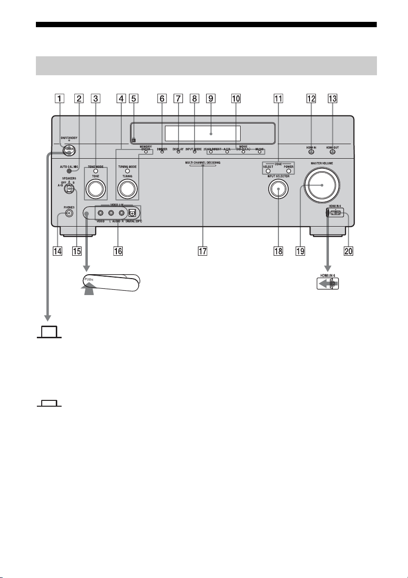
Description and location of parts
Front panel
To remove the cover
Press PUSH.
When you remove the cover, keep it out
of reach from children.
Status of the POWER button
Off
The receiver is turned off (initial
setting).
Press POWER to turn the receiver on.
You cannot turn the receiver on using
the remote.
To open the cover
Slide the cover to the
left.
On/Standby
Press
?/1 on the remote to turn the
receiver on or set it to the standby mode.
When you press POWER on the
receiver, the receiver will be turned off.
GB
8
Page 9

Name Function
A POWER Press to turn the
receiver on or off.
B AUTO CAL MIC
jack
Connects to the
supplied optimizer
microphone for the
Digital Cinema Auto
Calibration function
(page 51).
C TONE MODE Adjusts FRONT,
TONE
CENTER,
SURROUND/
SURROUND BACK
BASS and TREBLE.
Press TONE MODE
repeatedly to select
BASS or TREBLE,
then turn TONE to
adjust the level.
D MEMORY/
ENTER
TUNING MODE
TUNING
Press to operate a tuner
(FM/AM) and satellite
radio (XM/SIRIUS)
(USA/Canadian model
only).
E Remote sensor Receives signals from
remote commander.
F DIMMER Press repeatedly to
adjust brightness of the
display.
G DISPLAY Press repeatedly to
select information
displayed on the
display.
H INPUT MODE Press to select the input
mode when the same
components are
connected to both
digital and analog jacks
(page 117).
I Display
window
The current status of
the selected component
or a list of selectable
items appears here
(page 11).
Name Function
J 2CH/A.DIRECT Press to select sound
A.F.D.
MOVIE
field (page 82, 83, 86,
88).
(HD-D.C.S.)
MUSIC
K ZONE/
SELECT,
POWER
Press SELECT
repeatedly to select
zone 2, zone 3 or main
zone. Each time you
press POWER, the
output signals for the
selected zone will be
turned on or off
(page 105).
L HDMI IN Press to select the input
signal from the
component connected
to the HDMI IN jacks
(page 33).
M HDMI OUT Press to select output
signal to the c omponent
connected to the HDMI
OUT jacks (page 33).
N PHONES jack Connects to
headphones.
O SPEAKERS
(OFF/A/B/A+B)
Switch to OFF, A, B,
A+B of the front
speakers (page 50).
P VIDEO 2 IN
jacks
Connect to a portable
audio/video c omponent
such as a camcorder or
video game.
Q MULTI
CHANNEL
DECODING
Lights up when multichannel audio signals
are decoded.
lamp
continued
GB
9
Page 10

Name Function
R INPUT
SELECTOR
Turn to select the input
source to play back.
To select the input
source for zone 2 or
zone 3, press ZONE
SELECT (
qa) to select
zone 2 or zone 3 first
(“ZONE 2 INPUT” or
“ZONE 3 INPUT”
appears on the display),
then turn INPUT
SELECTOR to select
the input source.
S MASTER
VOLUME
Turn to adjust the
volume level of all
speakers at the same
time.
T HDMI IN 6 Connect to a
camcorder. The video
and sound from your
camcorder is input
(page 33).
10
GB
Page 11
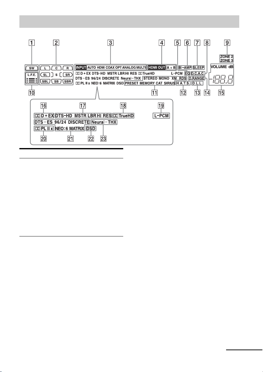
Indicators on the display
Name Function
A SW Lights up when subwoofer
is connected and the audio
signal is output from the
SUBWOOFER jack. While
this indicator lights up, the
receiver creates a
subwoofer signal based on
the L.F.E. signal in the disc
being played back or the
low frequency components
of the front channels.
continued
11
GB
Page 12

Name Function
B Playback
channel
indicators
The letters (L, C, R, etc.)
indicate the channels being
played back. The boxes
around the letters vary to
show how the receiver
downmixes the source
sound (based on the speaker
settings).
L Front Left
RFront Right
C Center (monaural)
SL Surround Left
SR Surround Right
S Surround (monaural or the
surround components
obtained by Pro Logic
processing)
SBL Surround Back Left
SBR Surround Back Right
SB Surround Back (the
surround back components
obtained by 6.1 channel
decoding)
Example:
Recording format (Front/
Surround): 3/2.1
Output channel: Surround
speakers are set to “NO.”
Sound Field: A.F.D. AUTO
LSW
CR
SL
SR
Name Function
C Input
indicators
Light up to indicate the
current input.
INPUT Lights up constantly with
either following the
corresponding indicators
that indicate the current
input status.
AUTO Lights up with the
corresponding indicators
that indicate the current
input when INPUT MODE
is set to “Auto.”
HDMI The receiver recognizes a
component connected via
an HDMI IN jack.
COAX Digital signal is input
through the COAXIAL
jack.
OPT Digital signal is input
through the OPTICAL jack.
ANALOG No digital signal is being
input. When INPUT
MODE is set to “Analog,”
or when the “2ch Analog
Direct” is being selected, it
also lights up.
MULTI The multi-channel input is
selected.
D HDMI OUT
A+B
Lights up when the signals
are output from the HDMI
OUT A or B jack. + also
lights up, along with A and
B when the signals are
output from both jacks.
E EQ Lights up when the
equalizer is activated.
F BI-AMP Lights up when surround
back speakers selection is
set to “BI-AMP.”
G SLEEP Lights up when the sleep
timer is activated.
12
GB
Page 13

Name Function
H D.C.A.C. Lights up when auto
calibration is activated.
I ZONE 2/
ZONE 3
Lights up while operation in
zone 2/zone 3 is being
enabled.
J L.F.E. Lights up when the disc
being played back contains
an L.F.E. (Low Frequency
Effects) channel. The L.F.E.
channel signal is actually
being reproduced, the bars
underneath the letters light
up to indicate the level.
Since the L.F.E. signal is
not recorded in all parts of
the input signal, the bar
indication will fluctuate
(and may turn off) during
playback.
Name Function
K Tuning
indicators
Lights up when the receiver
tunes in radio stations, or
satellite radio stations.
STEREO Stereo broadcast
MONO Monaural broadcast
XM
(USA/
Canadian
The XM Mini-Tuner and
Home Dock are connected
and “XM” is selected.
model only)
SIRIUS
(USA/
Canadian
The SiriusConnect Home
tuner is connected and
“SIRIUS” is selected.
model only)
CAT
(USA/
Canadian
The category mode is
selected during the satellite
radio operation.
model only)
RDS
(European
RDS information is
received.
model only)
PRESET The tuning mode is set to
the preset mode.
MEMORY A memory function, such as
Name Input, etc., is
activated.
L H.A.T.S. Lights up when the
H.A.T.S. (High quality
digital Audio Transmission
System) function is
activated.
M D.L.L. Lights up when the D.L.L.
(Digital Legato Linear)
function is activated.
N D.RANGE Lights up when dynamic
range compression is
activated.
O VOLUME Displays the current
volume.
continued
13
GB
Page 14

Name Function
P Dolby
Digital
Surround
indicators
Lights up one of the
respective indicators when
the receiver is decoding the
corresponding Dolby
Digital format signals.
;D Dolby Digital
;D+ Dolby Digital Plus
;D EX Dolby Digital Surround EX
Note
When playing a Dolby Digital
format disc, be sure that you
have made digital connections
and that INPUT MODE is not
set to “Analog.”
Q DTS-HD
indicators
Light up when the receiver
is decoding DTS-HD.
DTS-HD Lights up constantly with
the one of the following
indicators.
MSTR DTS-HD Master Audio
LBR DTS-HD Low Bit Rate
Audio
HI RES DTS-HD High Resolution
Audio
R ;TrueHD Lights up when the receiver
is decoding Dolby TrueHD.
S L-PCM Lights up when Linear
PCM (Pulse Code
Modulation) signals are
input.
Name Function
T Dolby
Pro Logic
indicators
Lights up one of the
respective indicators when
the receiver performs Dolby
Pro Logic processing. This
matrix surround decoding
technology can enhance
input signals.
;PL Dolby Pro Logic
;PLII Dolby Pro Logic II
;PLIIx Dolby Pro Logic IIx
Note
This indicator does not light
when either the center speaker
and surround speaker is not
connected.
U DTS(-ES)
indicators
Light up when DTS or
DTS-ES signals are input.
DTS Lights up when the receiver
is decoding DTS signals.
Either 96/24 or NEO:6 also
lights up depending on the
input signal format or
decoding format.
96/24 DTS 96/24 (96 kHz/24 bit)
decoding
NEO:6 DTS Neo:6 Cinema/Music
DTS-ES Lights up with the either
following indicator
depending on the input
signal decoding format.
DISCRETE DTS-ES Discrete 6.1
MATRIX DTS-ES Matrix 6.1
Note
When playing a DTS format
disc, be sure that you have
made digital connections and
that INPUT MODE is not set to
“Analog.”
V DSD Lights up when the receiver
is receiving DSD (Direct
Stream Digital) signals.
W Neural-THX Lights up when the receiver
applies Neural-THX
processing to input signals.
14
GB
Page 15

Rear panel
A DIGITAL INPUT/OUTPUT section
OPTICAL IN/
OUT jacks
COAXIAL IN
jacks
HDMI IN/
OUT* jacks
Connect to a DVD
player, Super Audio
CD player, etc. (page
25, 28, 34, 37, 38).
Connect to a DVD
player, Blu-ray Disc
Player, or a satellite
tuner. An image and
the sound are output
to TV or a projector
(page 25, 33).
B Control jacks for Sony equipment
and other external components
IR REMOTE
IN/OUT jacks
TRIGGER
OUT jacks
Connect an IR
repeater (page 105)
or an IR Blaster
(page 42).
Connect to interlock
on/off of the power
supply of other 12V
TRIGGER
compliant
components, or the
amplifier/receiver of
zone 2 or zone 3
(page 137).
C DMPORT
D ANTENNA section
FM ANTENNA
jack
AM
ANTENNA
jack
XM jack
(USA/Canadian
model only)
SIRIUS jack
(USA/Canadian
model only)
Connect to a Sony
DIGITAL MEDIA
PORT adapter
(page 28).
Connects to the FM
wire antenna (aerial)
supplied with this
receiver (page 44).
Connects to the AM
loop antenna (aerial)
supplied with this
receiver (page 44).
Connects to the XM
Mini-Tuner and
Home Dock (not
supplied) (page 74).
Connects to a
SiriusConnect Home
tuner (not supplied)
(page 74).
continued
15
GB
Page 16

E VIDEO/AUDIO INPUT/OUTPUT
section
AUD IO I N/
OUT jacks
VIDEO IN/
OUT* jacks
AUDIO OUT
jacks
VIDEO OUT
jack
EXT VIDEO IN
jack
Connect to a VCR or
a DVD player etc.
(page 25, 37, 38, 39).
Connect to the
component in zone 2
or zone 3 (page 105).
Connects to the
component when
you want to watch in
PIP (Picture in
Picture) window.
F LAN port
Connects to the
router when you
want to connect the
receiver to your
network.
I AUDIO INPUT/OUTPUT section
AUDIO IN/
OUT jacks
MULTI
CHANNEL
INPUT jacks
PRE OUT jacks Connect to an
Connect to a tape
deck or MD deck, et c
(page 31).
Connect to a Super
Audio CD player or
DVD player with an
analog audio jack for
7.1 channel or 5.1
channel sound
(page 30).
external power
amplifier.
J SPEAKERS section
Connects to speakers
(page 23).
* You can watch the selected input image when you
connect the HDMI OUT or MONITOR OUT jacks
to a TV (page 25).
G COMPONENT VIDEO INPUT/
OUTPUT section
Y, PB/CB, PR/
IN/OUT*
C
R
jacks
Connect to a DVD
player, TV, or a
satellite tuner (page
25, 37, 38).
H RS232C port
Used for
maintenance and
service.
GB
16
Page 17

Remote commander
You can use the supplied remote to operate the
receiver and to control the Sony audio/video
components that the remote is assigned to
operate.
Simple remote commander
(RM-AAU061)
This remote can only be used to operate the
receiver. You can control the main functions of
the receiver with simple operations using this
remote.
Name Function
A ?/1 (on/
standby)
B 2CH/
A.DIRECT
A.F.D.
MOVIE
MUSIC
Press to turn a receiver on or off.
Press to select sound field
(page 82, 83, 86, 88).
Name Function
C QUICK
CLICK
D
V/v/B/b
E OPTIONS Press to display and select items
F MENU Press to display the menu to
G DMPORT/
NETWORK
N Starts play.
x Stops play.
./> Skips tracks.
H INPUT
SELECTOR
I MASTER
VOLUME + /–
J MUTING Press to turn off the sound
K RETURN/
EXIT O
L DISPLAY Press to display the current
M GUI MODE Press to switch the display
Press to display the on-screen
remote on the TV screen.
Press V/v/B/b to select the
menu item. Then press to
enter the selection.
from option menus.
operate the receiver.
Press to operate the component
connected to the DIGITAL
MEDIA PORT adapter
(page 64), or to play back
content on the server (page 97).
Press to select the input source
to play back.
Press to adjust the volume level.
temporarily. Press the button
again to restore the sound.
Press to return to the previous
menu or exit the menu.
status of or information on
components connected to the
receiver.
Note
In the GUI MODE, press the
button to display the menu on
the TV screen.
mode of the menu between GUI
MODE (to display the menu on
the TV screen) and DISPLAY
MODE (to display the menu in
the display window).
continued
17
GB
Page 18
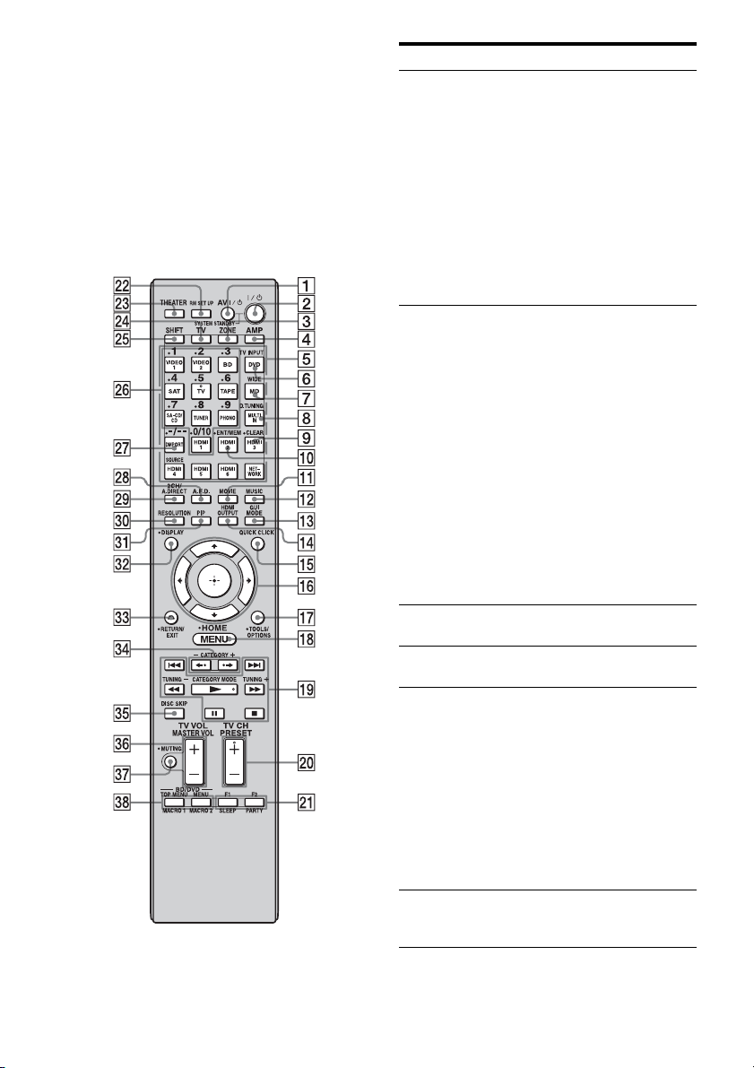
Multifunction remote
commander
(RM-AAL021/RM-AAL022)
The RM-AAL021 remote is supplied with the
European model only and RM-AAL022 is
supplied with the USA/Canadian model only.
The RM-AAL022 remote is used for
illustration purpose. Any differences in
operation are clearly indicated in the text, for
example, “USA/Canadian model only.”
Name Function
A AV ?/1 (on/
standby)
B ?/1 (on/
standby)
Press to turn on or off the audio/
video components that the
remote is assigned to operate
(page 172).
If you press ?/1 (2) button at
the same time, it will turn off
the receiver and other Sony
components (SYSTEM
STANDBY).
Note
The function of the AV ?/1
switch changes automatically
each time you press the input
button (5).
Press to turn the receiver on or
off.
If zone 2 or zone 3 is selected,
only the main receiver is turned
on or off with this button. To
turn off all components
including an amplifier in zone 2
or zone 3, press ?/1 and AV ?/
1 (1) at the same time
(SYSTEM STANDBY).
Saving the power in
standby mode.
When “Control for HDMI”
(page 142) and “Installer
Mode” (page 146) are set to
“OFF,” and the power for
zone 2/zone 3 is turned off.
C ZONE Press to switch the zone 2 or
D AMP Press to enable the receiver
E Input
buttons
F TV INPUT Press TV (wf), then press TV
zone 3 operation (page 105).
operation.
Press one of the buttons to
select the component you want
to use. When you press any of
the input buttons, the receiver
turns on. The buttons are
factory assigned to control Sony
components (page 62). You can
program the remote to control
non-Sony components
following the steps in
“Programming the remote”
(page 172).
INPUT to select the i nput signal
of a TV.
18
GB
Page 19
Name Function
G WIDE Press TV (wf), then press
H D.TUNING Press SHIFT (wg), then press to
I CLEAR Press SHIFT (wg), then press to
J ENT/MEM Press SHIFT (wg), then press
K MOVIE Press to select sound field for
L MUSIC Press to select sound field for
M GUI MODE Press to switch the display
N HDMI
OUTPUT
O QUICK
CLICK
P
V/v/B/b
Q TOOLS/
OPTIONS
R MENU
HOME
WIDE repeatedly to select the
wide picture mode.
enter direct tuning mode
(page 69, 76).
– clear a mistake when you
press the incorrect numeric
button.
– return to continuous
playback, etc. of the satellite
tuner or DVD player.
ENT/MEM to enter the value
after selecting a channel, disc,
or track using the numeric
buttons, or to store a station
during tuner operation.
movies (page 88).
music (page 86).
mode of the menu between GUI
MODE (to display the menu on
the TV screen) and DISPLAY
MODE (to display the menu in
the display window).
Press to select an HDMI jack
you want to output HDMI video
signals to (page 33).
Press to display the on-screen
remote on the TV screen.
Press V/v/B/b to select the
menu items. Then press to
enter the selection.
Press to display and select items
from option menus for receiver,
DVD player, TV, or Blu-ray
Disc Player, etc.
Press to display the menu used
to operate audio/video
components or a TV.
Name Function
S m/M
T PRESET
U F1/F2 Press BD or DVD (5), then
V RM SET UP Press to set up the remote
W THEATER Press to turn the Theater mode
X TV Press to enable the TV
Y SHIFT Press to light up the button. It
a)
a)
x
a)
X
a) b)
N
./>
Press to operate the DVD
player, Blu-ray Disc Player, CD
player, MD deck, tape deck, or
component connected to the
a)
DIGITAL MEDIA PORT
adapter etc.
CATEGORY
MODE
Press to select the category
mode for satellite tuner.
(USA/
Canadian
model only)
TUNING +/– Press to select station.
b)
/–
+
Press to register FM/AM/
satellite tuner stations or to
select preset stations.
b)
TV CH +
/– Press TV (wf), then press TV
CH +/– to operate the TV,
satellite tuner, VCR, etc.
press F1 or F2 to select a
component to operate.
• HDD/DISC combo
F1: HDD
F2: DVD disc, Blu-ray Disc
• DVD/VHS combo
F1: DVD disc, Blu-ray Disc
F2: VHS
PART Y Press to display confirmation
screen to start party mode
(page 110).
SLEEP Press AMP (4), then press
SLEEP to activate the sleep
timer function and the duration
which the receiver turns off
automatically (page 121).
(page 124).
on and off when connecting the
receiver to products featuring
“BRAVIA” Sync.
operation.
changes the remote button
function to activate the buttons
with pink printing.
continued
19
GB
Page 20
Name Function
Z Numeric
buttons
wj -/-- Press to
wk A.F.D. Press to select sound field
wl 2CH/
A.DIRECT
RESOLUTION
e;
ea PIP Press PIP to switch the image of
es DISPLAY Press to display the current
Press SHIFT (wg), then press to
– preset/tune to preset stations.
– select track numbers of the
CD player, DVD player,
Blu-ray Disc Player or MD
deck. Press -/-- (wj) to select
track number 10.
– select channel numbers of
the VCR or satellite tuner.
– After pressing TV (wf),
press the numeric buttons to
select the TV channels.
– select track numbers over 10
of the CD player, DVD
player, Blu-ray Disc Player,
or MD deck.
– select channel numbers over
10 of the TV, Satellite tuner
or the VCR.
(page 83).
Press to select sound field or to
switch the audio of the selected
input to analog signal without
any adjustment (page 82).
Press RESOLUTION
repeatedly to change the
resolution of signals output
from the HDMI OUT or
COMPONENT VIDEO
MONITOR OUT jack.
the PIP (Picture in Picture)
window. The image of the PIP
window is the one from the
EXT VIDEO IN jack. You can
swap the position of the main
screen and the PIP window by
pressing (qh).
Note
When the HDMI input is
selected on the main screen, you
cannot swap the position of the
main screen and the PIP window.
status of or information on
components connected to the
receiver.
Note
In the GUI MODE, press the
button to display the menu on
the TV screen.
Name Function
ed RETURN/
EXIT O
ef CATEGORY
+/–
(USA/
Canadian
model only)
B·/·b Press to select an album.
eg DISC SKIP Press to skip a disc when using
eh MASTER
VOL +/–
TV VOL +/– Press TV (wf), then press TV
ej MUTING Press to turn off the sound
ek BD/DVD/
TOP MENU,
MENU
MACRO1,
MACRO2
a)
See the table on page 171 for information on the
buttons that you can use to control each
component.
b)
The tactile dot is attached to these buttons (TV/5,
N, PRESET +/TV CH +). Use as a mark of
operation.
Press to return to the previous
menu or exit the menu while the
menu or on-screen guide of the
VCR, DVD player, or satellite
tuner is displayed on the TV
screen.
Press to select the category for
satellite tuner.
a multi-disc changer.
Press to adjust the volume level
of all speakers at the same time.
VOL +/– to adjust the volume
level of the TV.
temporarily. Press the button
again to restore the sound.
Press to display the menus of
the DVD player on the TV
screen. Then use V /v/B/b and
to perform a menu
operations.
Press AMP (4), then press
MACRO 1 or MACRO 2 to set
up the macro function
(page 175).
Notes
• Some functions explained in this section may not
work depending on the model.
• The above explanation is intended to serve as an
example only. Therefore, depending on the
component, the above operation may not be
possible or may operate differently than described.
20
GB
Page 21
Getting Started
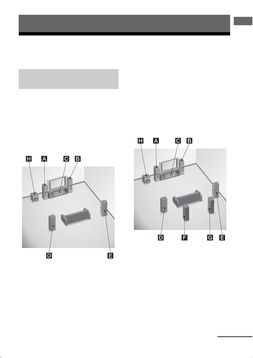
1: Installing speakers
This receiver allows you to use a 7.1 channel system (7 speakers and one subwoofer).
Getting Started
Enjoying a 5.1/7.1 channel
system
To fully enjoy theater-like multi-channel
surround sound requires five speakers (two
front speakers, a center speaker, and two
surround speakers) and a subwoofer (5.1
channel system).
Example of a 5.1 channel
speaker system configuration
You can enjoy high fidelity reproduction of
DVD or Blu-ray Disc software recorded sound
in the Surround EX format if you connect one
additional surround back speaker (6.1 channel
system) or two surround back speakers (7.1
channel system)
.
Example of a 7.1 channel
speaker system configuration
AFront left speaker
BFront right speaker
CCenter speaker
DSurround left speaker
ESurround right speaker
HSubwoofer
AFront left speaker
BFront right speaker
CCenter speaker
DSurround left speaker
ESurround right speaker
FSurround back left speaker
GSurround back right speaker
HSubwoofer
continued
21
GB
Page 22
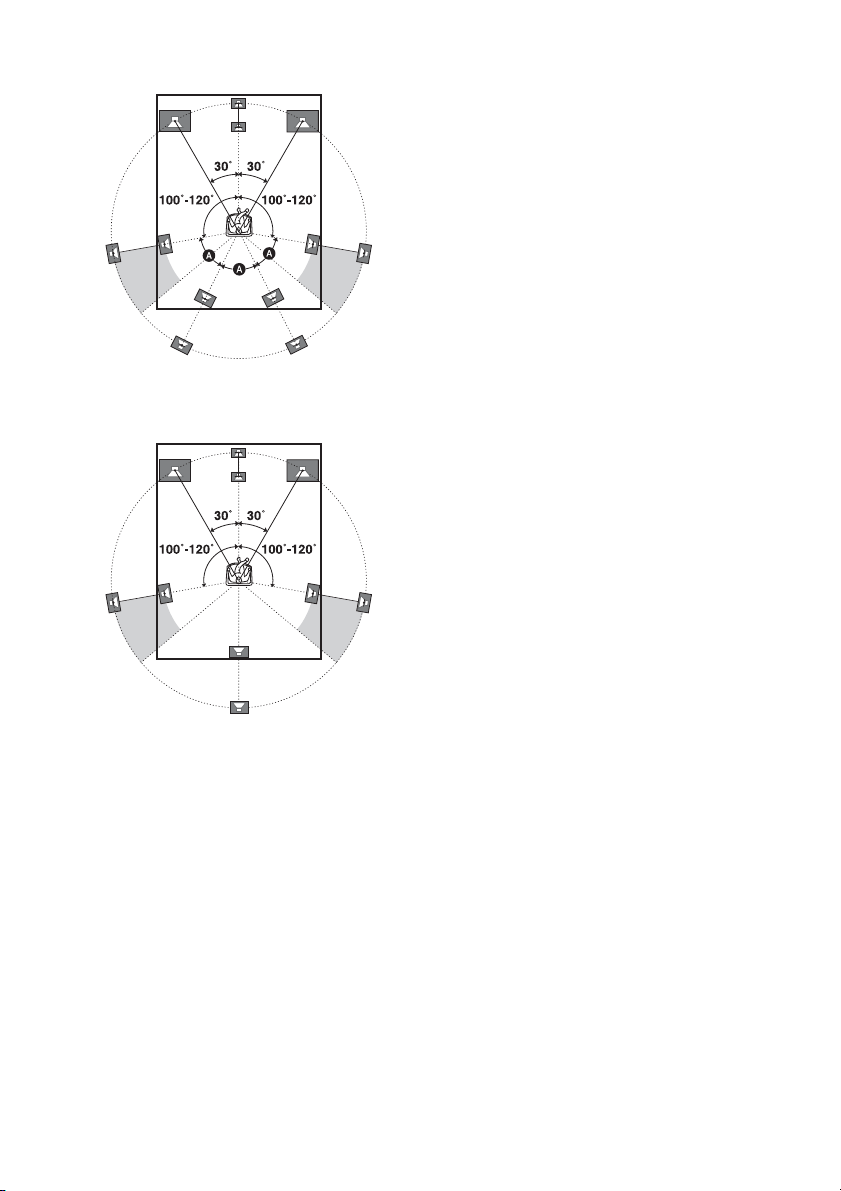
Tips
•The angle A should be the same.
• When you connect a 6.1 channel speaker system,
place the surround back speaker behind the seating
position.
• Since the subwoofer does not emit highly
directional signals, you can place it wherever you
want.
GB
22
Page 23
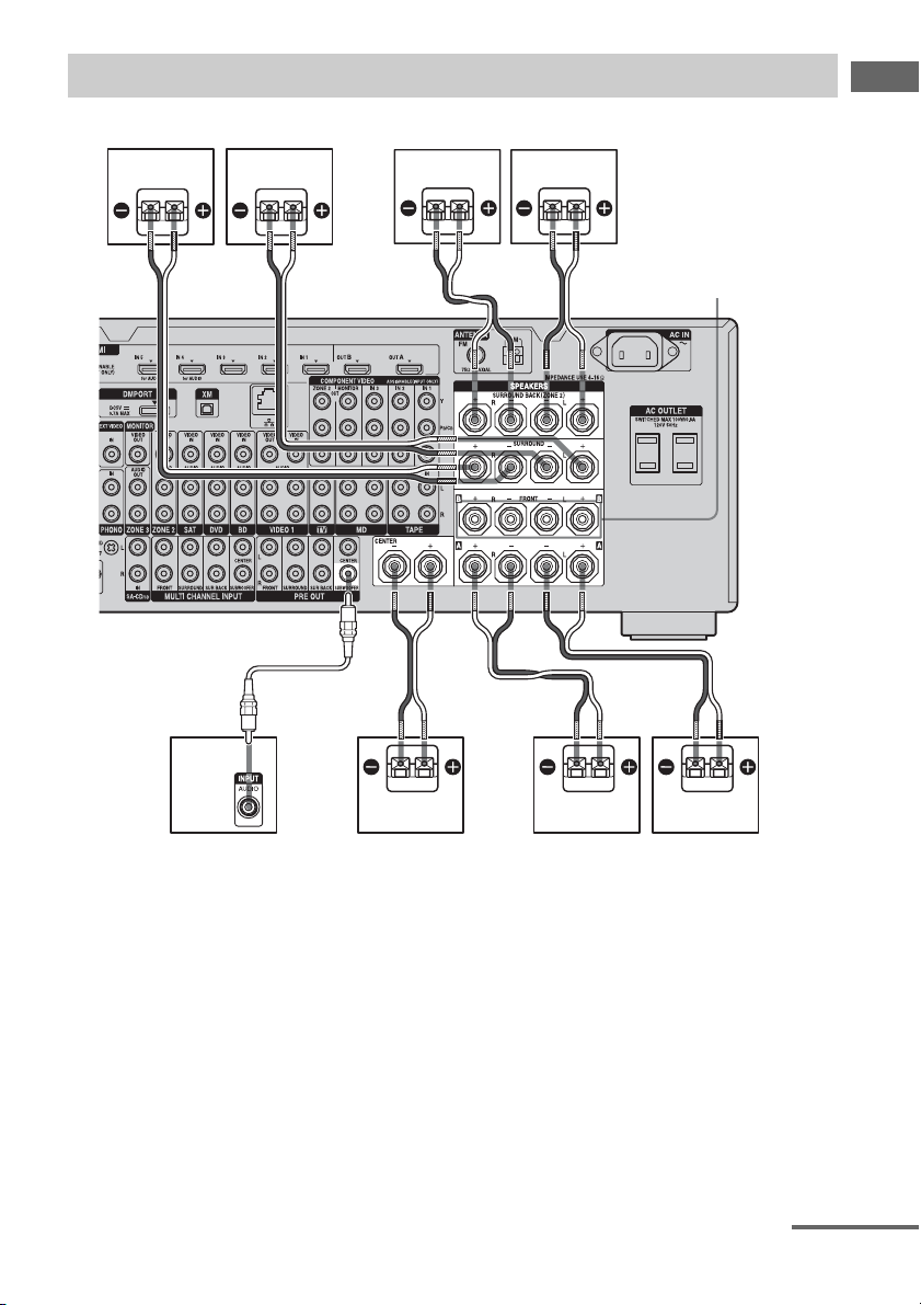
Connecting speakers
Before connecting cords, make sure to disconnect the AC power cord (mains lead).
Getting Started
HG F
B
A
BB
B
E
FRONT SPEAKERS
B terminals
a)
A Monaural audio cord (not supplied)
B Speaker cords (not supplied)
AFront speaker A (L)
BFront speaker A (R)
CCenter speaker
DSubwoofer
ESurround back speaker (L)
FSurround back speaker (R)
b)
c)
c)
GSurround speaker (L)
HSurround speaker (R)
C
BAD
a)
If you have an additional front speaker
system, connect them to the FRONT
SPEAKERS B terminals. You can select
the front speaker system you want to use
with the SPEAKERS switch (OFF/A/B/
A+B) on the front panel (page 50).
continued
23
GB
Page 24

b)
When you connect a subwoofer with an auto
standby function, turn off the function when
watching movies. If the auto standby
function is set to on, it turns to standby mode
automatically based on the level of the input
signal to a subwoofer, then sound may not be
output.
c)
If you connect only one surround back
speaker, connect it to the SURROUND
BACK SPEAKERS L terminals.
Notes
• When you connect all the speakers with a nominal
impedance of 8 ohms or higher, set “Impedance” in
the Speaker settings menu to “8 Ω.” In other
connections, set it to “4 Ω.” For details, see “7:
Setting the speakers” (page 48).
• Before connecting the AC power cord (mains
lead), make sure that metallic wires of the speaker
cords are not touching each other between the
SPEAKERS terminals.
Tip
To connect certain speakers to another power
amplifier, use the PRE OUT jacks. The same signal
is output from both the SPEAKERS terminals and
the PRE OUT jacks. For example, if you want to
connect just the front speakers to another amplifier,
connect that amplifier to the PRE OUT FRONT L
and R jacks.
ZONE 2 connection
You can assign the SURROUND BACK
SPEAKERS terminals E and F to the
speakers of the zone 2. Set “Sur Back Assign”
to “ZONE2” in the Speaker settings menu.
See “Using Multi-zone Features” (page 105)
for details on connection and operation in zone
2.
GB
24
Page 25
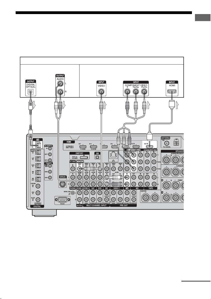
2: Connecting the monitor
You can watch the selected input image when you connect the HDMI OUT or MONITOR OUT
jacks to a TV. You can operate this receiver using a GUI (Graphical User Interface).
It is not necessary to connect all the cables. Connect audio and video cords according to the jacks
of your components.
TV monitor
Audio signals
Video signals
Getting Started
AB
CD E
A Optical digital cord (not supplied)
B Audio cord (not supplied)
C Video cord (not supplied)
D Component video cord (not supplied)
E HDMI cable (not supplied)
continued
25
GB
Page 26

Notes
• Before connecting cords, make sure to disconnect
the AC power cord (mains lead).
• Connect image display components such as a TV
monitor or a projector to the MONITOR VIDEO
OUT jack on the receiver. You may not be able to
record, even if you connect recording components.
• Turn on the receiver when the video and audio of a
playback component are being output to a TV via
the receiver. If the power supply of the receiver is
not turned on, neither video nor audio is
transmitted.
• Depending on the status of the connection between
the TV and the antenna (aerial), the image on the
TV screen may be distorted. In this case, place the
antenna (aerial) farther away from the receiver.
Tips
• The receiver has a video conversion function. For
details, see “Notes on converting video signals”
(page 41).
• The sound of the TV is output from the speakers
connected to the receiver if you connect the audio
output jack of the TV and the TV IN jacks of the
receiver. In this configuration, set the sound output
jack of the TV to “Fixed” if it can be switched
between either “Fixed” or “Variable.”
• The screen saver is activated when the GUI menu
is displayed on the TV screen and there has been no
operation attempted for 15 minutes.
26
GB
Page 27

3a: Connecting the audio components
How to hook up your
components
This section describes how to hook up your
components to this receiver. Before you begin,
see “Component to be connected” below for
the pages which describe how to connect each
component.
After hooking up all your components,
proceed to “4: Connecting the antennas
(aerials)” (page 44).
Component to be connected Page
Super Audio CD
player/ CD player
MD player With digital audio
Tape deck, Analog disc turntable 31
With digital audio
output
With multi-channel
audio output
With analog audio
output only
output
With analog audio
output only
28
30
31
28
31
Getting Started
27
GB
Page 28
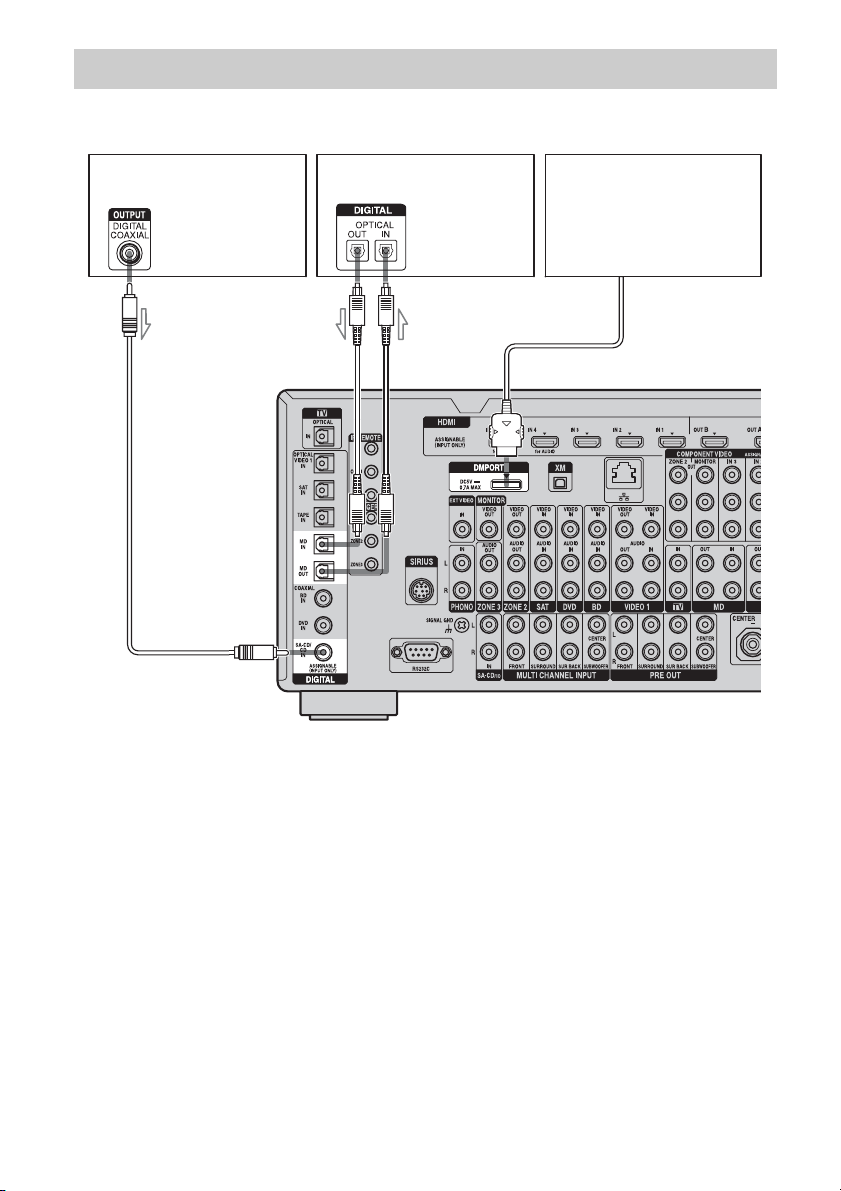
Connecting components with digital audio input/output jacks
The following illustration shows how to connect a Super Audio CD player, CD player, an MD deck
and DIGITAL MEDIA PORT adapter.
Super Audio CD
player, CD player
A
MD deck
DIGITAL MEDIA PORT
adapter
B
A Coaxial digital cord (not supplied)
B Optical digital cord (not supplied)
Notes
• When connecting optical digital cords, insert the
plugs straight in until they click into place.
• Do not bend or tie optical digital cords.
• Before connecting cords, make sure to disconnect
the AC power cord (mains lead).
• To disconnect the DIGITAL MEDIA PORT
adapter, observe the following precautions.
– Remove the DIGITAL MEDIA PORT adapter
after removing the cord when cords are
connected to the COMPONENT VIDEO jack.
– Remove the DIGITAL MEDIA PORT adapter
by squeezing the sides of the connector, since
the connector is locked in place.
GB
28
Tip
All the digital audio jacks are compatible with
32 kHz, 44.1 kHz, 48 kHz, 88.2 kHz and 96 kHz
sampling frequencies.
Page 29

Notes on playing a Super Audio
CD on a Super Audio CD player
• No sound is output when playing a Super
Audio CD on a Super Audio CD player
connected to only the COAXIAL SA-CD/
CD IN jack on this receiver. When you play
a Super Audio CD, connect the player to the
MULTI CHANNEL INPUT or SA-CD/CD
IN jacks. Refer to the operating instructions
supplied with the Super Audio CD player.
• Connect a player which can output DSD
signals from the HDMI jack to the receiver
using an HDMI cable.
• You cannot make digital recordings of a
Super Audio CD.
If you want to connect several
digital components, but cannot
find an unused input
See “Enjoying the sound/images from other
inputs (Input Assign)” (page 118).
Getting Started
29
GB
Page 30

Connecting components with multi-channel output jacks
If your DVD player, Blu-ray Disc Player or Super Audio CD player is equipped with multi-channel
output jacks, you can connect them to the MULTI CHANNEL INPUT jacks of this receiver to
enjoy multi-channel sound. Alternatively, the multi-channel input jacks can be used to connect an
external multi-channel decoder.
DVD player,
Blu-ray Disc Player,
Super Audio CD player,
etc.
A
B
A Audio cord (not supplied)
B Monaural audio cord (not supplied)
Notes
• Before connecting cords, make sure to disconnect
the AC power cord (mains lead).
• DVD player, Blu-ray Disc Player and Super Audio
CD players may not have the SURROUND BACK
jacks.
• When “Sur Back Assign” is set to “BI-AMP” or
“ZONE2” in the Speaker settings menu, the input
to the SUR BACK jacks is invalid.
GB
30
• Audio input signals from MULTI CHANNEL
INPUT jacks are not output to any audio output
jacks. The signals cannot be recorded.
Page 31
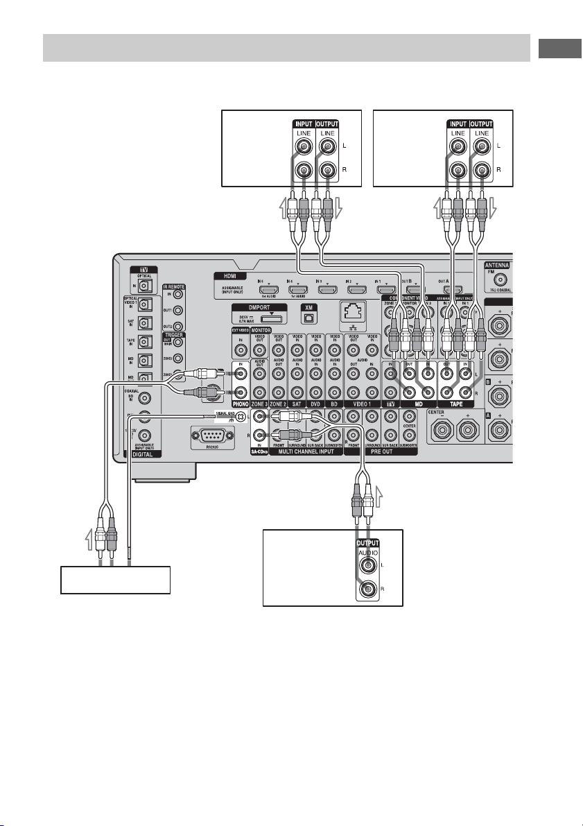
Connecting components with analog audio jacks
The following illustration shows how to connect a component with analog jacks, such as Super
Audio CD, CD player, MD deck, tape deck and turntable, etc.
Getting Started
A
MD deck
A
Tape deck
A
A
Tu rn t ab l e
A Audio cord (not supplied)
Notes
• If your turntable has a ground (earth) wire, connect
it to the (U) SIGNAL GND terminal.
• Before connecting cords, make sure to disconnect
the AC power cord (mains lead).
Super Audio CD
player, CD player
31
GB
Page 32
3b: Connecting the video components
How to hook up your
components
This section describes how to hook up your
components to this receiver. Before you begin,
see “Component to be connected” below for
the pages which describe how to connect each
component.
After hooking up all your components,
proceed to “4: Connecting the antennas
(aerials)” (page 44).
Component to be connected Page
TV monitor 25
With HDMI jack 33
DVD player, Blu-ray Disc Player 37
Satellite tuner, Set-top box 38
DVD recorder, VCR 39
Camcorder, video game, etc. 39
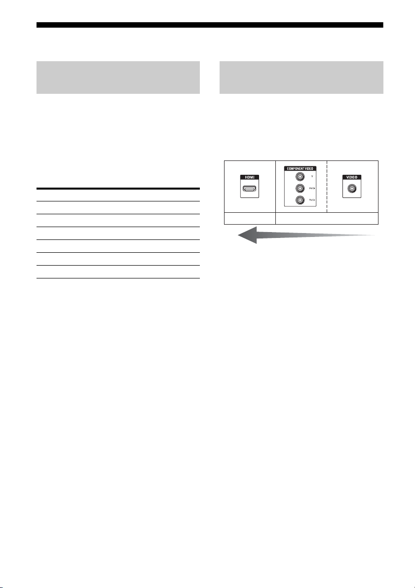
Video input/output jacks to be
connected
The image quality depends on the connecting
jack. See the illustration that follows. Select
the connection according to the jacks on your
components.
Digital Analog
High quality image
32
GB
Page 33

Connecting components with
HDMI jacks
HDMI is the abbreviated name for HighDefinition Multimedia Interface. It is an
interface which transmits video and audio
signals in digital format.
HDMI features
• A digital audio signals transmitted by HDMI
can be output from the speakers and the PRE
OUT jacks on this receiver. This signal
supports Dolby Digital, DTS, DSD, and
Linear PCM.
• Linear PCM (sampling frequency less than
192 kHz) with digital audio signals of up to
8 channels can be received with this receiver
using the HDMI IN jack.
• Analog video signals input to the VIDEO
jack, or COMPONENT VIDEO jacks can be
output as HDMI signals. Audio signals are
not output from HDMI OUT jacks when the
image is converted.
• This receiver supports DSD transmission
(Super Audio CD), extended by HDMI
ver1.2.
• This receiver supports High Bitrate Audio
(DTS-HD Master Audio, Dolby TrueHD),
Deep Color and x.v.Color (x.v.Colour)
transmission, extended by HDMI ver1.3.
• The HDMI jacks of this receiver support the
Control for HDMI function. The HDMI
OUT B jack, however, does not support the
Control for HDMI function.
• HDMI IN 4 and IN 5 are inputs which are
considered sound quality. Input IN 4 or IN 5
when you need higher quality sound. You
can also use IN 4 or IN 5 jacks in the same
manner as the HDMI IN 3.
• The HDMI IN 1, IN 2, and IN 6 jacks are
used for connecting a camcorder. Use the
HDMI IN 1, IN 2, and IN 6 jacks when you
connect a camcorder to the receiver.
Getting Started
continued
33
GB
Page 34

DVD player Satellite tuner/Set-top box
Audio/video
signals
Blu-ray Disc Player, PS3™,
hard disk recorder
Audio/video
signals
Audio/video
signals
To TV OPTICAL
IN jacks
Audio
signals
A
AA
CB
Audio/
video
signals
A
Audio/
video
signals
A
TV monitor, projector, etc.
A HDMI cable (not supplied)
We recommend that you use a Sony HDMI cable.
B Optical digital cord (not supplied)
C Audio cord (not supplied)
GB
34
Projector, etc.
Page 35

Getting Started
Audio/video signals
Camcorder
A HDMI cable (not supplied)
We recommend that you use a Sony HDMI cable.
To enjoy TV multi channel
surround sound broadcasting
You can listen to TV multi channel surround
sound broadcasting from the speakers
connected to the receiver.
Connect the OPTICAL output jack of the TV
to the OPTICAL IN jack of the receiver.
Tips
• Connect to at least one of the audio cords (B or
C).
• You can watch the image of the camcorder easily
with connecting your camcorder to the HDMI
IN 1, IN 2, and IN 6 jacks (page 114).
A
continued
35
GB
Page 36

Notes on connecting cables
• Use a High Speed HDMI cable. If you use a
Standard HDMI cable, 1080p or Deep Color
images may not be displayed properly.
• Sony recommends that you use an HDMIauthorized cable or Sony HDMI cable.
• We do not recommend using an HDMI-DVI
conversion cable. When you connect an
HDMI-DVI conversion cable to a DVI-D
component, the sound and/or the image may
not be output. Connect other audio cords or
digital connecting cords, then set “Input
Assign” in the Input Option menu when the
sound is not output correctly.
• Before connecting cables, make sure to
disconnect the AC power cord (mains lead).
Notes on HDMI connections
• Check the setup of the connected component
if an image is poor or the sound does not
come out of a component connected via the
HDMI cable.
• An audio signal input to the HDMI IN jack
is output from the speaker output jacks,
PHONES jack, HDMI OUT jack and PRE
OUT jacks. It is not output from any other
audio jacks.
• A video signal input to the HDMI IN jack
can only be output from the HDMI OUT
jack. The video input cannot be output from
the VIDEO OUT jacks or MONITOR
VIDEO OUT jacks.
• When you want to listen to the sound from
the TV speaker, set “Audio Out” to
“TV+AMP” in the HDMI settings menu. If
set to “AMP,” the sound is not output from
the TV speaker.
• Be sure to turn on the receiver when video
and audio signals of a playback component
are being output to a TV through this
receiver. If you set “Pass Through” to
“OFF,” unless the power is on, neither video
nor audio signals will be transmitted.
• Audio signals (sampling frequency, bit
length, etc.) transmitted from an HDMI jack
may be suppressed by the connected
component. Check the setup of the
connected component if an image is poor or
the sound does not come out of a component
connected via the HDMI cable.
• Sound may be interrupted when the
sampling frequency, the number of channels
or audio format of audio output signals from
the playback component is switched.
• When the connected component is not
compatible with copyright protection
technology (HDCP), the image and/or the
sound from the HDMI OUT jack may be
distorted or may not be output.
In this case, check the specification of the
connected component.
• Refer to the operating instructions of each
component connected for details.
• Set the image resolution of the player to
more than 720p/1080i to enjoy High Bitrate
Audio (DTS-HD Master Audio, Dolby
TrueHD).
• The image resolution of player may need
certain settings be made before you can
enjoy DSD and multi-channel Linear PCM.
Refer to the operating instructions of the
player.
• Not every HDMI component supports all
functions that are defined by the specified
HDMI version. For example, components
that support HDMI, ver. 1.3a, may not
support Deep Color.
36
GB
Page 37

Connecting a DVD player, Blu-ray Disc Player
The following illustration shows how to connect a DVD player, Blu-ray Disc Player.
It is not necessary to connect all the cables. Connect audio and video cords according to the jacks
of your components.
DVD player, Blu-ray Disc Player
Audio signals Video signals
Getting Started
ABC
A Optical digital cord (not supplied)
B Coaxial digital cord (not supplied)
C Audio cord (not supplied)
* When you connect a component equipped with an
OPTICAL jack, set “Input Assign” in the Input
menu.
D
E
D Video cord (not supplied)
E Component video cord (not supplied)
Notes
• To output multi-channel digital audio, set the
digital audio output setting on the DVD player,
Blu-ray Disc Player. Refer to the operating
instructions supplied with the DVD player, Blu-ray
Disc Player.
• Before connecting cords, make sure to disconnect
the AC power cord (mains lead).
37
GB
Page 38

Connecting a satellite tuner, Set-top box
The following illustration shows how to connect a satellite tuner, Set-top box.
It is not necessary to connect all the cables. Connect audio and video cords according to the jacks
of your components.
Satellite tuner, Set-top box
Audio signals Video signals
AB C D
A Optical digital cord (not supplied)
B Audio cord (not supplied)
C Video cord (not supplied)
D Component video cord (not supplied)
Note
Before connecting cords, make sure to disconnect
the AC power cord (mains lead).
GB
38
Page 39
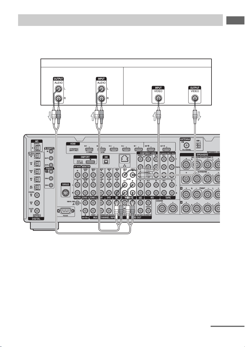
Connecting components with analog video and audio jack
The following illustration shows how to connect a component which has analog jacks such as a
DVD recorder or VCR, etc.
It is not necessary to connect all the cables. Connect audio and video cords according to the jacks
of your components.
DVD recorder, VCR
Audio signals Video signals
AB
Getting Started
A Audio cord (not supplied)
B Video cord (not supplied)
continued
39
GB
Page 40

To the VIDEO 2 IN jacks
C
Camcorder,
video game
C Audio/video cord (not supplied)
Note
Before connecting cords, make sure to disconnect
the AC power cord (mains lead).
Function for conversion of video signals
This receiver is equipped with a function for converting video signals.
• Composite video signals can be output as HDMI video and component video signals.
• Component video signals can be output as HDMI video and video signals.
As the initial setting, video signals input from the connected component are output to the HDMI
OUT or MONITOR OUT jacks as shown in the table below.
We recommend you set the video conversion function to match the resolution of the monitor you
are using.
For details on the video converting function, see “ Video settings” (page 140).
OUTPUT jack
INPUT jack
HDMI IN 1/2/3/4/5/6 a ––
VIDEO IN aa a
COMPONENT VIDEO IN aa a
a : Video signals are output.
– : Video signals are not output.
HDMI OUT A/B
COMPONENT VIDEO
MONITOR OUT
MONITOR VIDEO OUT
40
GB
Page 41

Notes on converting video
signals
• When video signals from a VCR, etc., are
converted on this receiver and then output to
your TV, depending on the status of the
video signal output, the image on the TV
screen may appear distorted horizontally or
no image may be output.
• HDMI video signals cannot be converted to
component video signals and video signals.
• The converted video signals are not output
from the VIDEO OUT jack.
• When you play a VCR with an image
improvement circuit, such as TBC, the
images may be distorted or may not be
output. In this case, set the image
improvement circuit function to off.
• The resolution of the signals output to the
COMPONENT VIDEO MONITOR OUT
jacks is converted up to 1080i. The
resolution of the signals output to the HDMI
OUT jacks are converted up to 1080p.
• COMPONENT VIDEO MONITOR OUT
jacks have restrictions on resolution when
the resolution of video signals protected by
copyright technology is converted.
Resolution of up to 480p can be output to the
COMPONENT VIDEO MONITOR OUT
jacks. The HDMI OUT jacks have no
restriction on resolution.
• Video signals for which the resolution has
been converted cannot be output from either
the COMPONENT VIDEO MONITOR
OUT jacks or the HDMI OUT jacks. The
video signals are output from the HDMI
OUT jacks when both are connected.
• Set “Resolution” to “AUTO” or “480i/576i”
in the Video settings menu to output the
video signals from the MONITOR VIDEO
OUT, COMPONENT VIDEO MONITOR
OUT jacks when both are connected.
To display Closed Caption
Set “Resolution” to “DIRECT” in the Video
settings menu when receiving a signal that
supports Closed Captions.
Use the same kind of cords for the input/output
signals.
To connect a recording
component
When recording, connect the recording
component to the VIDEO OUT jacks of the
receiver. Connect cords for input and output
signals to the same type of jack, as VIDEO
OUT jacks do not have an up-conversion
function.
Note
Signals output from the HDMI OUT or MONITOR
OUT jacks may not be recorded properly.
Getting Started
41
GB
Page 42
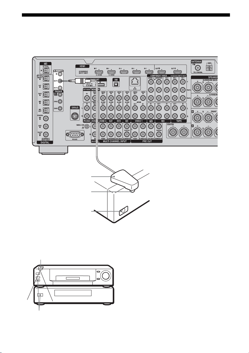
3c: Connecting the IR Blaster
Attach the supplied IR Blaster to components connected to the receiver. You can control
components connected to the receiver via the IR Blaster using the on-screen remote control.
IR Blaster
(supplied)
Infrared transmitter
Remote sensor
Place the components and the IR Blaster as
follows when you want to operate two
components with the IR Blaster.
IR Blaster
Remote sensors
GB
42
If the infrared receivers on the two
components do not line up as shown in the
illustration on the left, you must purchase an
optional IR Blaster (VM-50, not supplied) and
install it.
Note
For details on how to set up a component, refer to the
operating instructions of the component.
Tip
If the IR Blaster cable is too short, use a 3.5 mm jack
extension cable (not supplied).
Page 43

After referring to the operating instructions of
the components connected to the receiver,
make sure to place the IR Blaster just above or
below the remote sensor. Remote sensors on
Sony Recorders and other products are
identified by the symbol.
Note
Do not remove the backing paper from the IR
Blaster yet.
After configuring the settings, remove the backing
paper from the IR Blaster and fix it in place.
Getting Started
43
GB
Page 44

4: Connecting the antennas (aerials)
Connect the supplied AM loop antenna (aerial) and FM wire antenna (aerial).
AM loop antenna (aerial)
FM wire antenna (aerial) (supplied)
* The shape of the connector varies depending on
the area.
Notes
• To prevent noise pickup, keep the AM loop antenna
(aerial) away from the receiver and other
components.
• Be sure to fully extend the FM wire antenna
(aerial).
• After connecting the FM wire antenna (aerial),
keep it as horizontal as possible.
• Before connecting cords, make sure to disconnect
the AC power cord (mains lead).
(supplied)
44
GB
Page 45

5: Connecting to the network
Configuring your home network with DLNAcompliant devices.
If your computer is connected to the Internet,
you can connect this receiver to the Internet as
well, through the wired LAN connection.
Note
The method used to connect your computer to the
Internet depends on the devices, your ISP, your
computer, and the router used.
System requirements
The following system environment is required
to use the network function of the receiver.
A Broadband line connection
A Broadband line connection to the Internet is
required in order to listen to Rhapsody® or
SHOUTcast and to use the firmware update
function of the receiver. Rhapsody is only
available in the US.
• If the receiver is used in an environment in
which there is power supply noise from
electric products or in a noisy network
environment, use a shielded-type LAN
cable.
Getting Started
Modem
This is the device that is connected to the
broadband line to communicate with the
Internet. Some of these devices are integrated
with the router.
Router
• Use a router compatible with 100 Mbps or
greater transmission speeds to enjoy content
on your home network.
• We recommend that you use a router
equipped with the built-in DHCP (Dynamic
Host Configuration Protocol) server.
This function automatically assigns IP
addresses on the LAN.
LAN cable (CAT-5)
• We recommend that you use this type of
cable for a wired LAN.
Some flat-type LAN cables are easily
affected by noise. We recommend that you
use normal-type cables.
45
GB
Page 46
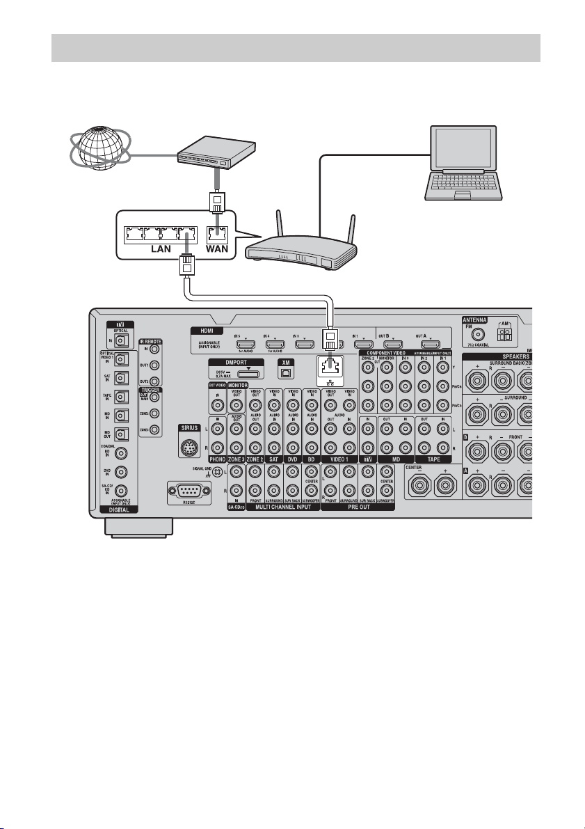
Configuration example
The following illustration is a configuration example of a home network with the receiver, a
computer.
We recommend that you use a wired connection.
LAN cable
(not supplied)
Internet Modem
Computer
LAN cable
(not supplied)
Note
A audio or video playback on the computer may
occasionally be interrupted when you use a wireless
connection.
Router
46
GB
Page 47
6: Preparing the receiver and the remote
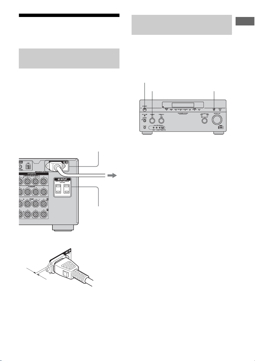
Connecting the AC power cord
(mains lead)
Connect the supplied AC power cord (mains
lead) to the AC IN terminal on the receiver,
then connect the AC power cord (mains lead)
to a wall outlet.
Notes
• Before connecting the AC power cord (mains
lead), make sure that metallic wires of the speaker
cords are not touching each other between the
SPEAKERS terminals.
• Connect the AC power cord (mains lead) firmly.
Performing initial setup
operations
Before using the receiver for the first time,
initialize the receiver by performing the
following procedure. This procedure can also
be used to return settings you have made to
their factory defaults.
POWER
TONE MODE HDMI IN
Getting Started
AC IN terminal
To the wall outlet
AC OUTLET
(USA/Canadian
model only)
AC power cord
(mains lead)
(supplied)
A several space is left between the plug and the
rear panel even when the power cord (mains
lead) is inserted firmly. The cord is supposed
be connected this way. This is not malfunction.
1 Press POWER to turn off the
receiver.
2 Hold down POWER while
pressing TONE MODE and
HDMI IN to turn on the receiver.
3 Release the TONE MODE and
HDMI IN after a few seconds.
After “MEMORY CLEARING...”
appears on the display for a while,
“MEMORY CLEARED.” appears.
All the settings you have changed or
adjusted are reset to the initial settings.
Note
It takes about 30 seconds for the memory to be
cleared completely. Do not turn the receiver off until
“MEMORY CLEARED.” appears on the display.
47
GB
Page 48
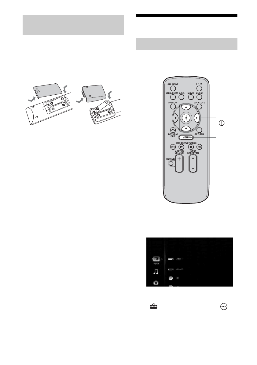
Inserting batteries into the
remote
7: Setting the speakers
Insert two R6 (size-AA) batteries in the RMAAL021 or RM-AAL022 remote commander.
Insert two R6 (size-AA) batteries in the RMAAU061 remote control.
Observe the correct polarity when installing
batteries.
RM-AAL021
RM-AAL022
RM-AAU061
Notes
• Do not leave the remote in an extremely hot or
humid place.
• Do not use a new battery with old ones.
• Do not mix manganese batteries and other kinds of
batteries.
• Do not expose the remote sensor to direct sunlight
or lighting apparatuses. Doing so may cause a
malfunction.
• If you do not intend to use the remote for an
extended period of time, remove the batteries to
avoid possible damage from battery leakage and
corrosion.
• When you replace the batteries, the programmed
remote codes may be cleared. If this happens,
program the remote codes again (page 172).
Tip
When the remote no longer operates the receiver,
replace all the batteries with new ones.
Setting the speaker impedances
Set the appropriate speaker impedance for the
speakers you are using.
V/v/b,
MENU
1 Press MENU.
The menu is displayed on the TV screen.
48
2 Press V/v repeatedly to select
“ Settings,” then press or
b.
The Settings menu list appears on the TV
screen.
GB
Page 49

Getting Started
3 Press V/v repeatedly to select
“Speaker,” then press or b.
4 Press V/v repeatedly to select
“Impedance,” then press .
5 Press V/v repeatedly to select
“4 Ω” or “8 Ω” depending on
the speakers you are using,
then press .
The parameter you have selected is
entered.
To exit the menu
Press MENU.
Notes
• If you are not sure of the impedances of the
speakers, refer to the operating instructions
supplied with your speakers. (This information is
often on the back of the speaker.)
• When you connect all speakers with a normal
impedance of 8 ohms or higher, set “Impedance” to
“8 Ω.” When connecting other types of speakers,
set it to “4 Ω.”
• When you connect front speakers to both the
SPEAKERS A and B terminals, connect the
speakers with a normal impedance of 8 ohms or
higher.
– When you connect speakers with impedance of
16 ohms or higher in both “A” and “B”
configuration:
Set “Impedance” to “8 Ω” in the Speaker
settings menu.
– For other types of speakers in other
configurations:
Set “Impedance” to “4 Ω” in the Speaker
settings menu.
49
GB
Page 50

Selecting the front speakers
You can select the front speakers you want to
drive.
SPEAKERS switch
Set the SPEAKERS switch to select
the front speaker system you want
to drive.
Note
This setting is not available when headphones are
connected.
Set to To select
A The speakers connected to the
FRONT SPEAKERS A terminals.
B The speakers connected to the
FRONT SPEAKERS B terminals.
A+B The speakers connected to both the
FRONT SPEAKERS A and B
terminals (parallel connection).
OFF No audio signals are output from
any speaker terminals, or the PRE
OUT jacks.
8: Calibrating the
appropriate speaker
settings automatically
(Auto Calibration)
The DCAC (Digital Cinema Auto Calibration)
function allows you to perform automatic
calibration, such as checking the connection
between each speaker and the receiver,
adjusting the speaker level, and measuring the
distance of each speaker from your seating
position automatically.
Before you perform the auto
calibration
Before you perform the auto calibration, set up
and connect the speakers (page 21-24).
• The AUTO CAL MIC jack is used for the
supplied optimizer microphone only. Do not
connect other microphones. Doing so may
damage the receiver and the microphone.
• During the measurement, the sound that
comes out of the speakers is very loud. The
volume of the sound cannot be adjusted. Pay
attention to the presence of children or to the
effect on your neighborhood.
• Perform the measurement in a quiet
environment to avoid the effect of noise and
get a more accurate measurement.
• If there are any obstacles in the path between
the optimizer microphone and the speakers,
the calibration cannot be performed
correctly. Remove any obstacle from the
measurement area to avoid measurement
error.
• When you use a bi-amplifier connection, set
“Sur Back Assign” to “BI-AMP” in the
Speaker settings menu before you perform
auto calibration.
Notes
• The auto calibration function does not work if
headphones are connected.
• Cancel MUTING if it is set to on.
50
GB
Page 51

Optimizer microphone
1 Connect the supplied optimizer
microphone to the AUTO CAL
MIC jack.
2 Set up the optimizer
microphone.
Place the optimizer microphone at your
seating position. Use a stool or tripod so
that the optimizer microphone remains at
the same height as your ears. Orient the L
end of the optimizer microphone toward
the front left speaker and the R end of the
optimizer microphone toward the front
right speaker.
Note
When you position the optimizer microphone
at the center of the two speakers, if the angle
between the two speakers is too narrow, the
optimizer microphone cannot measure the left
and right speakers properly.
On setting up the active
subwoofer
• When a subwoofer is connected, turn on the
subwoofer and turn up the volume
beforehand. Turn the MASTER VOLUME
knob to just before the mid-point.
• If you connect a subwoofer with the
crossover frequency function, set the value
to maximum.
• If you connect a subwoofer with an auto
standby function, set it to off (deactivated).
Note
Depending on the characteristics of the subwoofer
you are using, the setup distance value may be
further away from the actual position.
To use the receiver as a preamplifier
You can use the auto calibration function when
you use the receiver as a pre-amplifier.
In this case, the distance value shown on the
display may differ from the actual distance
value. However, there will be no problems
even if you continue to use the receiver with
that value.
Performing auto calibration
The auto calibration function allows you to
measure the following:
• Speaker connections
• Polarity of speakers
• Speaker distance
• Speaker size
• Speaker level
• Frequency characteristics
a) This receiver corrects signals by analog
downmix processing only for the center speaker
and subwoofer when the multi-channel input is
selected. The correction is invalid for other
speakers.
b) The measurement result is not utilized in the
following cases.
– The multi-channel input is selected.
– “2ch Analog Direct” is being used.
a)
b)
b)
b) c)
Getting Started
continued
51
GB
Page 52

c) • Signals with a sampling frequency of 88.2 kHz
and higher are always played back at either
44.1 kHz or 48 kHz.
• The measurement result is not utilized when
Dolby TrueHD signals with a sampling
frequency of 176.4 kHz and higher are being
received.
V/v/B/b,
MENU
3 Press V/v repeatedly to select
“Auto Calibration,” then press
or b.
4 Press V/v repeatedly to select
“Quick Setup,” then press .
The screen on which you can select the
item to be measured appears.
1 Press MENU.
The menu is displayed on the TV screen.
2 Press V/v repeatedly to select
“ Settings,” then press or
b.
The Settings menu list appears on the TV
screen.
GB
52
5 Press V/v repeatedly and to
un-check the items you do not
want to measure, then press b.
The confirmation screen, asking whether
you are ready to start measurement,
appears.
Page 53

6 Press to select “Start.”
The measurement starts in five seconds.
When the measurement ends, a beep
sounds and the measurement result
appears on the TV screen.
7 Press to select “Next.”
“Save auto calibration (auto speaker
setup)?” appears. To save the
measurement results, follow the steps in
“Saving the measurement results”
(page 54).
If a warning message or error code
appears on the screen, see “Message list
after auto calibration measurement”
(page 55).
Note
When the speaker(s) is (are) out of the phase, “Out
Phase” is displayed on the TV screen. The “+” and
“–” terminals of the speaker may be connected the
other way around. However, depending on the
speakers, “Out Phase” appears on the TV screen
even though the speakers are connected properly.
This is because of the speakers’ specifications. In
this case, you can continue to use the receiver.
Tips
• Operations other than turning the receiver on or off
are deactivated during the measurement.
• In the following situations, the measurements have
not been performed correctly or auto calibration
cannot be performed.
– when connecting special speakers, such as
dipole speakers.
– when using the zone 2/zone 3 function in zone 2/
zone 3.
• You can change the unit of distance use in
“Distance Unit” in the Speaker settings menu.
To cancel the measurement
The measurement is cancelled when you
change the volume, switch functions, change
the setting of the SPEAKERS switch, or
connect headphones.
Getting Started
53
GB
Page 54

Saving the measurement results
To save the measurement results obtained in
“Performing auto calibration” (page 51),
proceed with the following steps.
1 Press B/b to select “Yes” in
step 7 in “Performing auto
calibration” (page 51), then
press .
The selecting screen of the calibration
type appears.
2 Press V/v repeatedly to select
the auto calibration type, then
press .
Parameter Explanation
Full Flat Makes the measurement of
frequency from each
speaker flat.
Engineer Sets the frequency to one
that matches that of the
Sony listening room
standard.
Front Reference Adjusts the characteristics
of all the speakers to match
the characteristics of the
front speaker.
OFF Sets the auto calibration EQ
to off.
The measurement results are saved.
4 Press .
Notes
• After reflecting the results of a compensation for a
frequency characteristic, signals with a sampling
frequency of 88.2 kHz and higher are always
played back at either 44.1 kHz or 48 kHz.
• The frequency response measurement result is not
utilized in the following cases.
– The multi-channel input is selected.
– “2ch Analog Direct” is being used.
– Dolby TrueHD signals with a sampling
frequency of 176.4 kHz and higher are being
received.
Tip
The size of a speaker (LARGE/SMALL) is
determined by the low characteristics. The
measurement results may vary, depending on the
position of the optimizer microphone and speakers,
and the shape of the room. It is recommended that
you follow the measurement results. However, you
can change those settings in the Speaker settings
menu. Save the measurement results first, then try to
change the settings if you want.
3 Press b.
The exit screen appears.
GB
54
Page 55
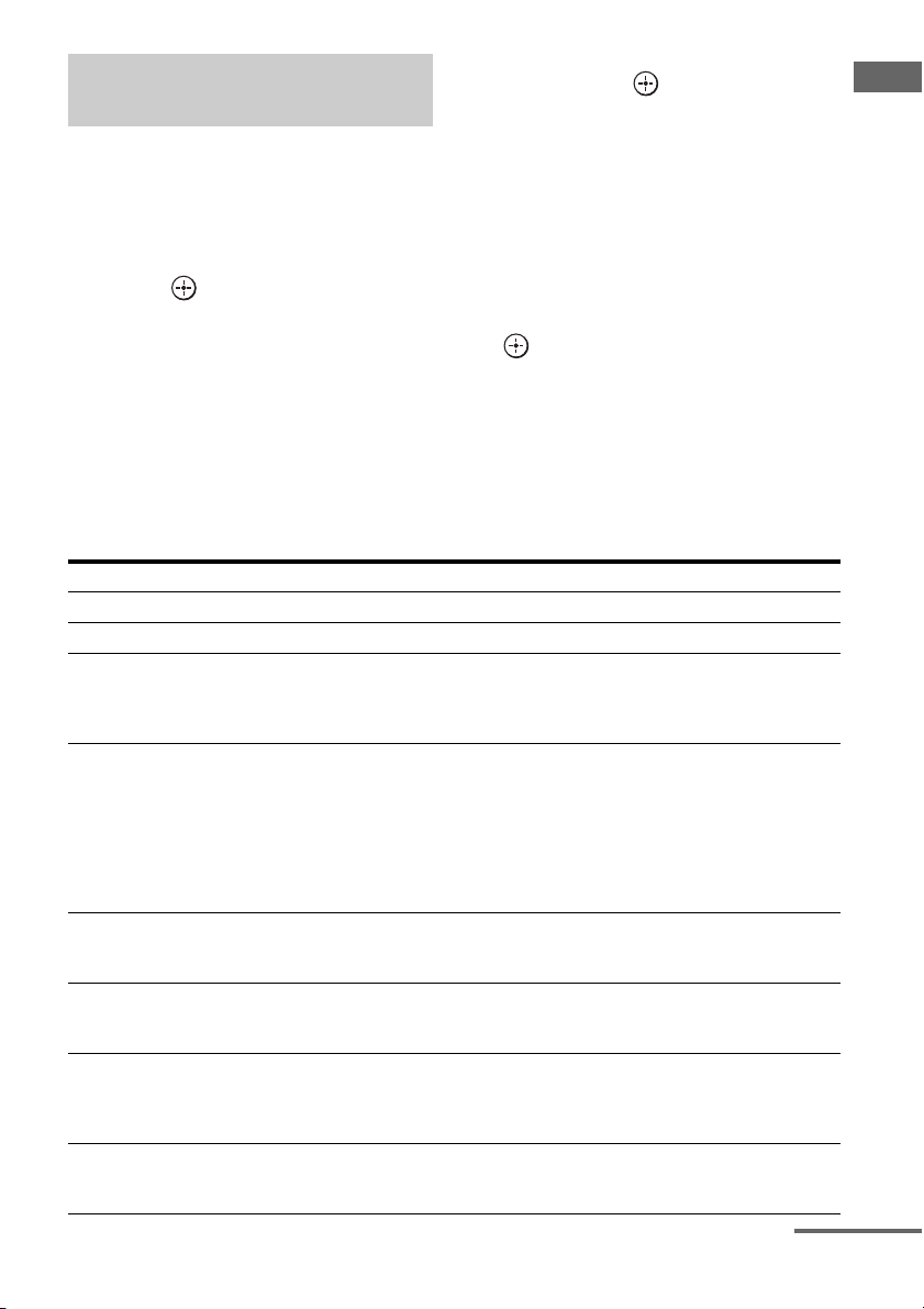
Checking the auto calibration
results
then press .
3 Repeat steps 5 to 7 in
2 Press B/b to select “Retry,”
If a warning message or error code appears in
step 7 of “Performing auto calibration”
(page 51), check the problem of the error and
perform auto calibration again.
1 Press B/b to select “Yes,” then
press when “Error occurred
during calibration, press to
investigate.” appears on the
screen.
Confirm the details of the measurement
results, then proceed with the appropriate
remedy.
Message list after auto calibration measurement
Display Explanation
Code 30 Headphones are connected. Remove the headphones and perform the auto calibration again.
Code 31 SPEAKERS (OFF/A/B/A+B) is set to OFF. Set it to others and re-perform the measurement.
Code 32 None of the speakers were detected. Make sure that the optimizer microphone is connected
Code 33 • None of the front speakers are connected or only one front speaker is connected.
Code 34 Speakers are not placed in the proper position. Speakers or an optimizer microphone on the
Warning 40 The measurement has completed. However, the noise level is high. You may be able to
Warning 41
Warning 42
Warning 43 The distance and position of a subwoofer cannot be detected. Or the angle of the speaker
properly and reperform the measurement.
If the optimizer microphone is connected properly but the error code appears, the optimizer
microphone cable may be damaged or improperly connected.
• The optimizer microphone is not connected.
• Either the left or right surround speaker is not connected.
• Surround back speakers are connected even though surround speakers are not connected.
Connect the surround speaker(s) to the SURROUND terminals.
• The surround back speaker is connected only to the SURROUND BACK SPEAKERS R
terminals. When you connect only one surround back speaker, connect it to the
SURROUND BACK SPEAKERS L terminals.
right or left may be placed wrongly. See “1: Installing speakers” (page 21) and check the
speaker position.
perform the measurement properly if you try it again, even though the measurement cannot
be performed in all environments. Try to perform the measurement in a quiet environment.
The input from the microphone is too big.
• It may be too close the distance between the speaker and the microphone.
Retry the measurement after setting apart from each other.
• It may be that the volume is too big when you use the receiver as a preamp.
position cannot be detected. This may be caused by noise. Try to perform the measurement
in a quiet environment.
“Performing auto calibration”
(page 51).
To save measurement results
that caused an error without
taking a remedy
Press B/b to select “No”, then press
1
when “Error occurred during
calibration, press to investigate.”
appears on the screen.
2 Follow the steps in “Saving the
measurement results” (page 54) to
save the measurement results.
continued
55
Getting Started
GB
Page 56

Display Explanation
Warning 44 Measurement has been completed. However the speakers are not placed in the proper position
with respect to each other. See “1: Installing speakers” (page 21) and check the relative
positions of the speakers.
NO WARNING There is no warning information.
---------- No speakers are connected.
Tip
Depending on the position of the subwoofer, the
measurement results for polarity may vary.
However, there will be no problems even if you
continue to use the receiver with that value.
56
GB
Page 57

9: Configuring the network settings of the receiver
The network settings for the receiver must be
set correctly to use the network functions of
the receiver.
You can make the required network settings
for the receiver by following the instructions
provided by an initial setup wizard.
The procedure used to set up the IP address
automatically (DHCP) is explained below.
In this case, the router that is connected to the
receiver or the Internet provider must support
DHCP.
V/v/b,
MENU
3 Press V/v repeatedly to select
“Network,” then press or b.
Getting Started
4 Press V/v repeatedly to select
“Network Setup,” then press
.
“Start Network function Setup Wizard”
appears on the TV screen.
5 Press to select “Next.”
6 Press to select “Connect
Automatically (DHCP).”
“Success! The receiver is now connected
to network.” appears on the TV screen
when you have succeeded in making a
connection.
If the failure screen is displayed, perform
the process referring to “Network Setup”
(page 144), after you have completed this
process.
7 Press to select “Finish.”
To set the network settings
manually
See “To set the IP address manually”
(page 144) or “To set the Proxy server
manually” (page 144).
Note
The wizard screen appears on the TV screen each
time you use the network function, until the network
function setup has been completed.
1 Press MENU.
The menu is displayed on the TV screen.
2 Press V/v repeatedly to select
“ Settings,” then press or
b.
57
GB
Page 58

10: Preparing a computer to use as a server
A server is a device which delivers content
(music, photos, and videos) to a DLNA device
on a home network.
You can play back content stored on a
computer on a home network with this receiver
via that network after you have installed
application software such as VAIO Media plus
which has a DLNA compliant sever function.
What you can do with VAIO
Media plus
VAIO Media plus is an application software
that enables you to quickly find content on
your home network, such as music, photos,
and videos, and view the content on the
computer through the home network.
By connecting other devices to VAIO Media
plus, you can also find and view the content on
the connected devices through the home
network. For example, you can enjoy photos
and music, stored on your computer, on your
TV and audio device or play a TV program,
recorded with a hard disk recorder, on your
computer.
If you use a VAIO computer, you can deliver
content saved on an external hard disk drive or
in Network-Attached Storage (NAS).
Note
If you use a computer other than a VAIO, you can
only deliver content saved on the internal disk drive
of that computer.
System Requirements
Operating System
Windows XP Home Edition/Professional/
Media Center Edition 2004/Media Center
Edition 2005 (SP3, 32 bit)
Windows Vista Home Basic/Home Premium/
Business/Ultimate (SP1, 32 bit/64 bit)
Computer
Windows XP Windows Vista
Computer IBM PC/AT compatible
CPU Intel Celeron M
Memory 512 MB or more
Graphic
chip
Display 800 × 600 or higher resolution
HDD 500 MB or more is recommended.
Network 100Base-TX or higher
Sound
card
processor
1.40 GHz or higher
(Intel Core 2 Duo
1.80 GHz or higher
is recommended.)
(1 GB or more is
recommended.)
Equipped with graphic chip by Intel,
NVIDIA or ATI.
DirectX 9.0c compatible video card
(DirectX 9.0c/128 MB compatible
video card and the latest driver are
recommended.)
Direct Sound compatible sound card
Intel Core Duo
1.33 GHz or higher
(Intel Core 2 Duo
2.26 GHz or higher
is recommended.)
1 GB or more
(2 GB or more is
recommended.)
Note
Sony does not guarantee trouble-free operation on
all computers that satisfy the system requirements.
Other software operating on background may affect
the operation of this software.
Installing the VAIO Media plus
application software on a
computer
When you use VAIO Media plus as server
software, install on your computer the VAIO
Media plus application software provided on
the CD-ROM supplied with the receiver by
following steps below.
If an older version of VAIO Media plus has
already been installed on your computer,
uninstall the following three programs using
“Programs and Features” (for Windows Vista)
or “Add or Remove Programs” (for Windows
XP) in Control Panel beforehand.
• VAIO Media plus
• VAIO Content Folder Watcher
• VAIO Content Folder Setting
58
GB
Page 59

1 Turn on your computer and
login as an administrator.
2 Insert the supplied CD-ROM
into the CD-ROM drive of your
computer.
The installation launcher starts
automatically, then a Software Setup
window appears on the screen.
If installation launcher does not start
automatically, double-click
“SetupLauncher.exe” on the disc.
Guide to on-screen display operation
You can display the menu of the receiver on
the TV screen and select the function you want
to use on the TV screen by pressing V/v/B/b
and on the remote.
To display the menu of the receiver on the TV
screen, make sure that the receiver is in “GUI
MODE” following the step in “To turn “GUI
MODE” on and off” (page 60).
Getting Started
CD-ROM (VAIO Media
plus application
software) (supplied)
3 Install the VAIO Media plus
application software following
the instructions given in the
message on the screen.
Referring to help files
For VAIO Media plus operations, refer to the
help files.
Click “ Settings” in the Home Menu
window, then select “ Help” to display help
files.
GUI
MODE
RETURN/
EXIT O
V/v/B/b,
OPTIONS
MENU
59
GB
Page 60
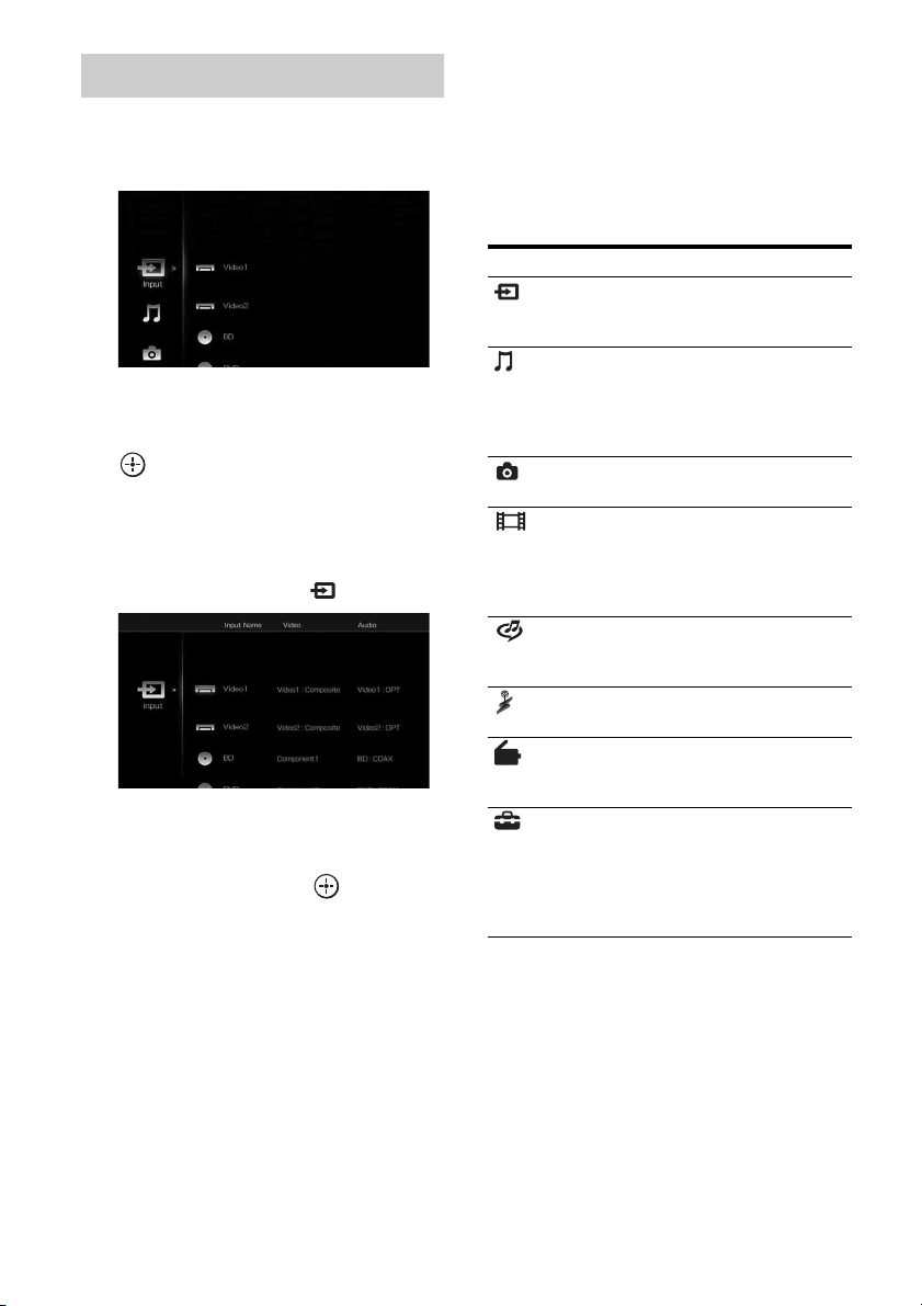
Using the menu
1 Press MENU.
The menu is displayed on the TV screen.
2 Press V/v repeatedly to select
the menu you want, then press
or b to enter the menu
mode.
The menu item list appears on the TV
screen.
Example: When you select “ Input”
3 Press V/v repeatedly to select
the menu item you want to
adjust, then press to enter
the menu item.
4 Repeat steps 2 and 3 to select
the parameter you want.
To turn “GUI MODE” on and off
Press GUI MODE. “GUI MODE ON” or
“GUI MODE OFF” is displayed in the
display window of the receiver, depending
on the mode selected.
Overview of the main menus
Menu icon Description
Input Selects the input source
Music Selects the music from the
Photo Select the photos from the
Video Select the images from the
Rhapsody Selects the Rhapsody radio
SHOUTcast Selects the SHOUTcast radio
FM/AM/XM/
SIRIUS
Settings You can adjust the settings of
component connected to the
receiver (page 62).
audio component connected
to the DIGITAL MEDIA
PORT adapter (page 64) or
server on the home network.
server on the home network.
video component connected
to the DIGITAL MEDIA
PORT adapter (page 64) or
server on the home network.
service (page 98). Rhapsody
is only available in the US.
service (page 101).
Selects the built-in FM/AM
radio or satellite tuner
connected (page 68, 73).
the speakers, the surround
effect, equalizer, audio,
video and other inputs
connected to the HDMI jacks
(page 127).
To return to the previous screen
Press RETURN/EXIT O.
To exit the menu
Press MENU.
GB
60
Page 61
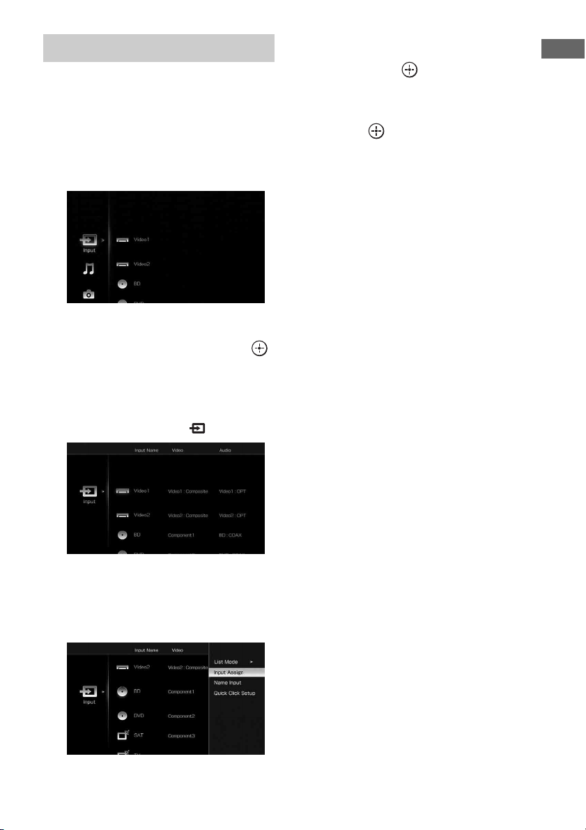
Using the option menus
When you press OPTIONS, the option menus
for the selected main menu are displayed. You
can select a related function without
reselecting the menu.
1 Press MENU.
The menu is displayed on the TV screen.
2 Press V/v repeatedly to select a
menu you want, then press
or b to enter the menu mode.
The menu item list appears on the TV
screen.
Example: When you select “ Input”
4 Press V/v repeatedly to select
the option menu item you want,
then press .
5 Press V/v repeatedly to select
the parameter you want, then
press .
To exit the menu
Press MENU.
Getting Started
3 Press OPTIONS while the menu
item list is displayed.
The option menu appears.
61
GB
Page 62

Playback
Enjoying sound/images from the component connected to the receiver
V/v/B/b,
OPTIONS
MENU
MASTER
VOLUM E
MUTING
Press MENU.
1
The menu is displayed on the TV screen.
2 Press V/v repeatedly to select
“ Input,” then press or b.
The menu item list appears on the TV
screen.
3 Press V/v repeatedly to select
the component you want, then
press .
The menu screen disappears and the
playback screen of the external input
appears.
Selected input Components that
Vid eo1,
Vid eo2
BD Blu-ray Disc Player,
DVD DVD player, etc.,
SAT Satellite tuner, etc.,
TV TV connected to the TV
Tape Tape deck, etc.,
MD MD deck, etc.,
SA-CD/CD Super Audio CD or CD
Phono Turntable, etc.,
Multi in Component connected
HDMI1, 2, 3,
4, 5, 6
can be used
VIDEO 1, 2 VCR, etc.,
connected to the
VIDEO 1 or VIDEO 2
jack.
etc., connected to the
BD jack.
connected to the DVD
jack.
connected to the SAT
jack.
jack.
connected to the TAPE
jack.
connected to the MD
jack.
player, etc., connected
to the SA-CD/CD jack.
connected to the
PHONO jack.
to the MULTI
CHANNEL INPUT
jack.
HDMI components
connected to the
HDMI1, HDMI2,
HDMI3, HDMI4,
HDMI5, or HDMI6 jack.
4 Turn on the component and
start playback.
5 Press MASTER VOLUME +/– to
adjust the volume.
Tips
• You can adjust the volume differently depending
on the speed with which you turn the MASTER
VOLUME knob.
62
GB
Page 63

To turn the volume up or down quickly: turn the
knob quickly.
To make fine adjustment: turn the knob slowly.
• You can adjust the volume differently depending
on the length of time you press and hold the
MASTER VOLUME +/– button on the remote.
To turn the volume up or down quickly: press and
hold the button.
To make a fine adjustment: press the button and
release it immediately.
To activate the muting function
Press MUTING on the remote. To cancel,
press MUTING on the remote again or press
MASTER VOLUME + to raise the volume.
To avoid damaging your
speakers
Before you turn off the receiver, be sure to turn
down the volume level.
Naming the input (Name Input)
You can enter a name of up to 8 characters for
inputs and display it.
This is convenient for labeling the jacks with
the names of the connected components.
1 Press V/v repeatedly on the
“ Input” screen to select the
input you want to name.
2 Press OPTIONS.
The option menu appears.
3 Press V/v repeatedly to select
“Name Input,” then press .
The soft keyboard appears on the screen.
To cancel naming input
Press V/v/B/b to select “Cancel,” then
press .
Changing the display items (List
Mode)
When you select “ Input,” you can change
the items to be displayed.
1 Press V/v repeatedly on the
“ Input” screen to select the
input you want.
2 Press OPTIONS.
The option menu appears.
3 Press V/v repeatedly to select
“List Mode,” then press .
4 Press V/v repeatedly to select
the item you want to display,
then press .
• Input Assign
Input name and audio/video input jack
assigned to the input are displayed in a
list.
• Sound Field
Input name and the sound field selected
for the input are displayed in a list.
•A/V Sync
Input name and the delay set on the “A/
V Sync” menu for the input are
displayed in a list.
Playback
4 Press V/v/B/b and to select
a character one by one to enter
the name.
5 Press V/v/B/b to select
“Finish,” then press .
The name you entered is registered.
63
GB
Page 64

Enjoying sound/images from the components connected to the DIGITAL MEDIA PORT
The DIGITAL MEDIA PORT is for enjoying
sound/images from a portable audio source or
computer by connecting a DIGITAL MEDIA
PORT adapter.
Available DIGITAL MEDIA PORT adapters
vary in each area.
For details on connecting the DIGITAL
MEDIA PORT adapter, see “Connecting
components with digital audio input/output
jacks” (page 28).
You can use the following Sony DIGITAL
MEDIA PORT adapters:
• TDM-BT1/BT10 Bluetooth™ Wireless
Audio Adapter
• TDM-NW10 DIGITAL MEDIA PORT
Adapter
• TDM-iP10/iP50 DIGITAL MEDIA PORT
Adapter
• TDM-MP10 DIGITAL MEDIA PORT
Adapter
The DIGITAL MEDIA PORT adapter is an
optional product.
Notes
• Do not connect an adapter other than the DIGITAL
MEDIA PORT adapter.
• Before d isconnecting the DIGITAL MEDIA PORT
adapter, make sure to turn the receiver off using the
remote.
• Do not connect or disconnect the DIGITAL
MEDIA PORT adapter to/from the receiver while
the system is turned on.
• Depending on the type of DIGITAL MEDIA
PORT adapter, the images are also output.
• Do not connect to the receiver a DIGITAL MEDIA
PORT adapter that uses a network function such as
TDM-NC1 Wireless Network Audio Client.
You can use the network function of the receiver
without using a DIGITAL MEDIA PORT adapter.
V/v/b,
MENU
MASTER
VOLUM E
1 Press MENU.
The menu is displayed on the TV screen.
2 Press V/v repeatedly to select
“ Music” or “ Video,” then
press or b.
3 Press V/v repeatedly to select
“DMPORT” or a component
connected to the DIGITAL
MEDIA PORT adapter, then
press .
The component connected to the
DIGITAL MEDIA PORT adapter is
recognized and “DMPORT” on the screen
will change to the respective component’s
name with an icon. If the adapter
connected cannot be recognized,
“DMPORT” is displayed on the TV
screen.
64
GB
Page 65
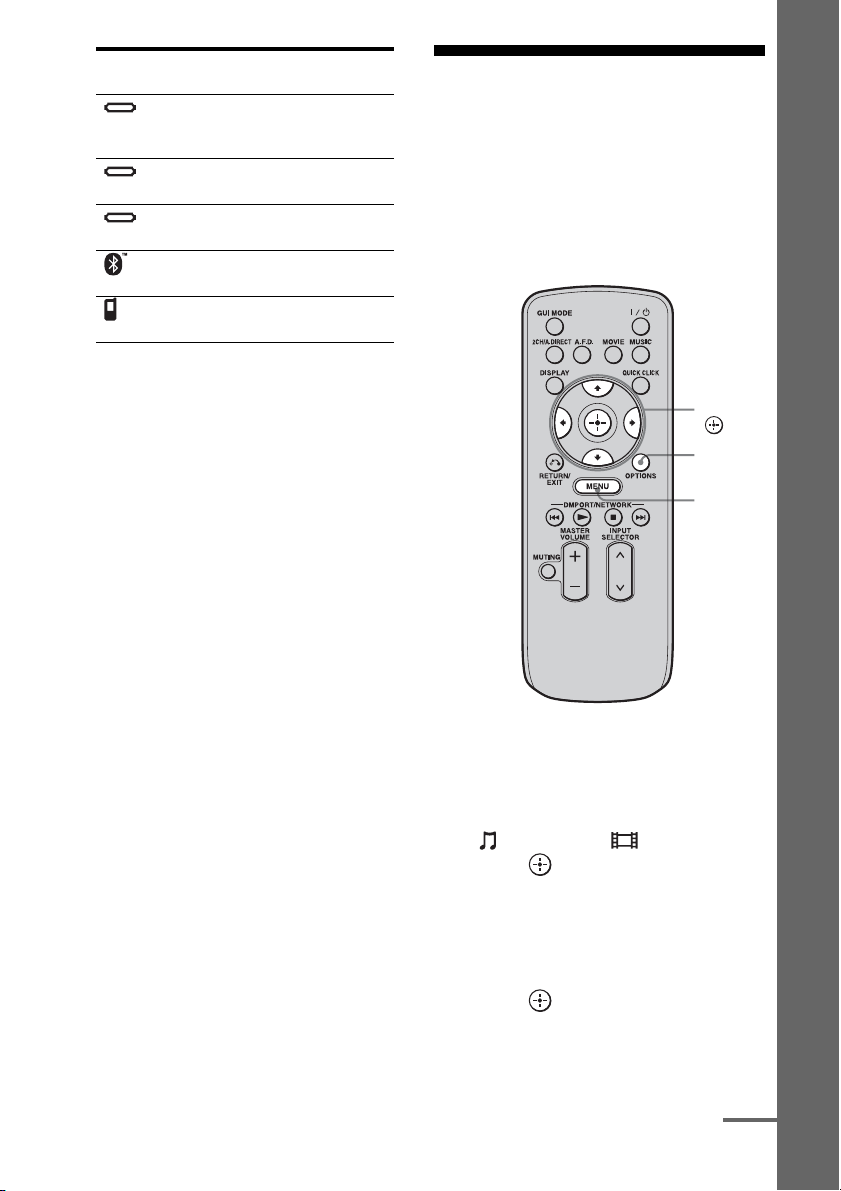
Icon Component that is
DMPORT
iPod The iPod model recognized
Walkman The Network Walkman
Bluetooth The Bluetooth drive
Mobile
Phone
connected
A component other than one
of the following is
connected.
is connected.
recognized is connected.
recognized is connected.
The Mobile Phone
recognized is connected.
4 Select a track you want to play
using the component
connected to the DIGITAL
MEDIA PORT adapter.
5 Press MASTER VOLUME +/– to
adjust the volume.
Operating the TDM-iP50 using the GUI menu of the receiver
Playback
Make sure that “System GUI” is selected in
step 4 in “Changing the operation screen using
the DIGITAL MEDIA PORT” (page 67).
V/v/B/b,
OPTIONS
MENU
1 Press MENU.
The menu is displayed on the TV screen.
2 Press V/v repeatedly to select
“ Music” or “ Video,” then
press or b.
3 Press V/v repeatedly to select
the component connected to
the DIGITAL MEDIA PORT
adapter you want to play, then
press .
The contents list appears.
continued
65
GB
Page 66

4 Press V/v/B/b and to select
track or content from the
contents list.
The following content lists are just
examples. They may vary depending on
the components connected to the receiver.
In case of iPod
Music Playlists > Playlist > Track
Artists > Artist > Album > Track
Albums > Album > Track
Songs > Track
Genres > Genre > Artist > Album > Track
Composers > Composer > Album > Track
Audiobooks > Track
Video Movies > Content
TV Shows > Episode > Content
Music Videos > Artist > Content
Video Podcast > Episode > Content
5 Press MASTER VOLUME +/– to
adjust the volume.
Selecting the playback mode
x Shuffle
Plays all the tracks in random order.
•Off
Deactivates the shuffle play mode.
•Albums
Plays all the tracks on an album in random
order.
• Songs
Plays all the tracks in “Songs” in random
order.
x Repeat
Plays one or all the tracks repeatedly.
•Off
Deactivates the repeat play mode.
•One
Plays one track repeatedly.
•All
Plays all the tracks repeatedly.
x Audiobook Speed
Selects the display speed of the Audiobook.
•Low
Slows the display speed.
•Normal
Sets the display speed to standard.
•High
Increases the display speed.
1 Play back the track you want to
listen to following the steps
outlined in “Operating the TDMiP50 using the GUI menu of the
receiver” (page 65).
2 Press OPTIONS.
The option menu appears.
3 Press V/v repeatedly to select
“Shuffle,” “Repeat,” or
“Audiobook Speed,” then press
.
4 Press V/v repeatedly to select
the mode you want to select
from the following, then press
.
GB
66
DIGITAL MEDIA PORT message
list
Message appears Explanation
No Adapter The adapter is not connected.
No Device There is no device connected
to the adapter.
No Audio No audio file was found.
Loading The data is being read.
No Item No item was found.
Page 67

Changing the operation screen
using the DIGITAL MEDIA PORT
You can change the operation screen using the
GUI menu. The DMPORT Control mode is
supported by the DIGITAL MEDIA PORT
adapters like TDM-iP50. This mode is not
supported by other adapters.
1 Press V/v repeatedly on the
“ Music” or “ Video”
screen to select the DIGITAL
MEDIA PORT adapter you want,
then press or b.
2 Press OPTIONS.
The option menu appears.
3 Press V/v to select “DMPORT
Control,” then press .
If “DMPORT Control” is not displayed,
refer to the operating instructions
supplied with component for details on
operating that component.
4 Press V/v repeatedly to select
the mode you want, then press
.
You can select the following modes in this
menu;
• System GUI
This mode is for the TDM-iP50. The list
of tracks will be displayed on the GUI
screen of the receiver. You can select a
track you want and play back it on each
GUI screen.
• Adapter GUI
This mode is for the TDM-iP50. The
menu of the adapter will be displayed on
the TV screen.
•iPod
This mode can be selected only when
the TDM-iP50 is connected.
To operate the TDM-iP50 using
the adapter menu
Make sure that “Adapter GUI” is selected in
step 4 in “Changing the operation screen using
the DIGITAL MEDIA PORT” (page 67).
For details on operating the adapter using the
adapter GUI menu, refer to the operating
instructions supplied with the adapter you are
using.
To operate the TDM-iP50 using
the iPod menu
Make sure that “iPod” is selected in step 4 in
“Changing the operation screen using the
DIGITAL MEDIA PORT” (page 67).
For details on operating the iPod, refer to the
operating instruction supplied with the iPod.
Playback
67
GB
Page 68

Tuning
Tuning into a station
automatically (Auto Tuning)
Listening to FM/AM radio
You can listen to FM and AM broadcasts
through the built-in tuner. Before operation,
make sure you have connected the FM and
AM antennas (aerials) to the receiver
(page 44).
Tip
The tuning scale for direct tuning is shown below.
• FM band 100 kHz (USA/Canadian model)
50 kHz (European model)
• AM band 10 kHz* (USA/Canadian model)
9 kHz (European model)
* The AM tuning scale can be changed (page 71).
V/v/b,
OPTIONS
MENU
1 Press MENU.
The menu is displayed on the TV screen.
2 Press V/v repeatedly to select
“ FM” or “ AM,” then press
or b.
The FM or AM menu list appears on the
TV screen.
3 Press V/v to select “Auto
Tuning,” then press .
4 Press V/v.
Press V to scan from low to high, press v
to scan from high to low.
The receiver stops scanning whenever a
station is received.
In case of poor FM stereo
reception
Tune in the station you want to listen to
1
using Auto Tuning, Direct Tuning
(page 69), or select the preset station
you want (page 72).
2 Press OPTIONS.
The option menu appears.
3 Press V/v to select “FM Mode,” then
press .
68
4 Press V/v to select “MONO,” then
press .
GB
Page 69

Tuning into a station directly
(Direct Tuning)
Enter the frequency of a station directly by
using the numeric buttons on the multifunction
remote. This operation cannot be performed
using the simple remote.
SHIFT
Numeric
buttons
AMP
V/v/b,
5 Press SHIFT, then press the
numeric buttons to enter the
frequency, then press .
Example 1: FM 102.50 MHz
Select 1 b 0 b 2 b 5 (b 0*)
Example 2: AM 1,350 kHz
Select 1 b 3 b 5 b 0
*Press the numeric button 0 when you are
using the European model.
Tip
If you have tuned in an AM station, adjust the
direction of the AM loop antenna (aerial) for
optimum reception.
If you cannot tune in a station
“– – – .– – MHz” appears and then the display
returns to the current frequency.
Make sure you have entered the right
frequency. If not, repeat step 5. If you still
cannot tune in a station, the frequency is not
used in your area.
Tuning
MENU
1 Press AMP.
The receiver can be operated using the
remote.
2 Press MENU.
The menu is displayed on the TV screen.
3 Press V/v repeatedly to select
“FM” or “AM,” then press
or b.
4 Press V/v to select “Direct
Tuning,” then press .
69
GB
Page 70

Receiving RDS broadcasts
(European model only)
This receiver also allows you to use RDS
(Radio Data System), which enables radio
stations to send additional information along
with the regular program signal. You can
display RDS information.
Select a station on the FM band you
want to listen to using Auto Tuning
(page 68) or Direct Tuning.
When you tune in a station that provides RDS
services, the Program Service Name and
Program Type are displayed on the TV screen.
Program type
indication
News News programs
Current Affairs Topical programs that expand on
Information Progra ms offering information on
Sport Sports programs
Education Educational programs, such as
Drama Radio plays and serials
Cultures Programs about national or
Science Programs about the natural
Varied Speech Other types of programs such as
Pop Music Popular music programs
Rock Music Rock music programs
Easy Listening Easy Listening
Light Classics M Instrumental, vocal, and choral
Serious Classics Performances of major
Description
current news
a wide spectrum of subjects,
including consumer affairs and
medical advice
“how-to” and advice programs
regional culture, such as language
and social concerns
sciences and technology
celebrity interviews, panel
games, and comedy
music
orchestras, chamber music,
opera, etc.
Program type
indication
Other Music Music that does not fit into any
Weather & Metr Weather information
Finance Stock market reports and trading,
Children’s Progs Programs for children
Social Affairs Programs about people and the
Religion Programs of religious content
Phone In Programs where members of the
Travel & Touring Programs about travel. Not for
Leisure &
Hobby
Jazz Music Jazz programs
Country Music Country music programs
National Music Programs featuring the popular
Oldies Music Programs featuring oldies music
Folk Music Folk music programs
Documentary Investigative features
None Any programs not defined above
Description
categories above, such as Rhythm
& Blues and Reggae
etc.
things that affect them
public express their views by
phone or in a public forum
announcements that are located
by TP/TA.
Programs on recreational
activities such as gardening,
fishing, cooking, etc.
music of the country or region
Notes
• RDS is operable only for FM stations.
• Not all FM stations provide RDS service, nor do
they provide the same type of services. If you are
not familiar with the RDS services in your area,
check with your local radio stations for details.
• RDS may not work properly if the station you
tuned to is not transmitting the RDS signal
properly or if the signal strength is weak.
• If there is an emergency announcement by
government authorities, “Alarm -Alarm!” flashes in
the display.
• If a station does not provide a particular RDS
service, “No XX” (such as “No Clock Time”)
appears on the display.
70
GB
Page 71

• When a station broadcasts radio text data, it is
displayed at the same rate at which it is sent from
the station. Any change in this rate is reflected in
the display rate of the data.
• The RDS information is shown on the display of
this receiver.
Changing the AM tuning scale
(USA/Canadian model only)
You can change the AM tuning scale to either
9 kHz or 10 kHz on the receiver.
POWER
TUNING MODE
1 Press POWER to turn off the
receiver.
2 While holding down TUNING
MODE, press POWER on the
receiver.
Presetting FM/AM radio stations
You can preset up to 30 FM and 30 AM
stations. Then you can easily tune in the
stations you often listen to.
Tuning
V/v/B/b,
OPTIONS
MENU
3 Change the current AM tuning
scale to 9 kHz (or 10 kHz).
To reset the scale to 10 kHz (or 9 kHz),
repeat the procedure above.
Note
All preset stations will be erased when you change
the tuning scale.
1 Tune in the station that you
want to preset using Auto
Tuning (page 68) or Direct
Tuning (page 69).
In case of poor FM stereo reception,
switch the FM reception mode (page 68).
2 Press OPTIONS.
The option menu appears.
3 Press V/v to select “Memory,”
then press .
4 Press V/v to select a preset
number, then press .
The station is stored as the selected preset
number.
continued
71
GB
Page 72

5 Repeat steps 1 to 4 to preset
another station.
You can store stations as follows:
• AM band: AM1 to AM30
• FM band: FM1 to FM30
Tuning to preset stations
1 Press MENU.
The menu is displayed on the TV screen.
2 Press V/v repeatedly to select
“ FM” or “ AM,” then press
or b.
3 Press V/v to select the preset
number station you want.
Preset numbers from 1 to 30 are available.
Naming preset stations (Name
Input)
1 On “FM” or “AM” screen,
press V/v to select the preset
number on which you want to
name.
To cancel naming input
Press V/v/B/b to select “Cancel,” then
press .
2 Press OPTIONS.
The option menu appears.
3 Press V/v repeatedly to select
“Name Input,” then press .
The soft keyboard appears on the screen.
4 Press V/v/B/b and to select
a character one by one to enter
the name.
5 Press V/v/B/b to select
“Finish,” then press .
The name you entered is registered.
GB
72
Page 73

Listening to satellite
should visit xmradio.ca or call XM Listener
Care at 1-877-GETXMSR (1-877-438-9677).
radio
(USA/Canadian model only)
To listen to Satellite Radio, you’ll need to
connect either a SIRIUS or XM Satellite Radio
tuner (sold separately) to your satellite-ready
receiver. Satellite Radio is available to
residents of the US (except Alaska and
Hawaii) and Canada.
Satellite Radio delivers a variety of
commercial-free music from categories
ranging from Pop, Rock, Country, R&B,
Dance, Jazz, Classical and many more plus
coverage of all the top professional and college
sports including play by play games from
select leagues and teams. Additional
programming includes expert sports talk,
uncensored entertainment, comedy, family
programming, local traffic and weather and
news from your most trusted sources.
Whether you purchase a SIRIUS or XM tuner,
you’ll need to activate and subscribe to begin
enjoying the service. Easy to follow
installation and setup instructions are provided
with the satellite tuners. Whichever service
you choose, there are a variety of
programming packages available, including
the option of adding “The Best of SIRIUS”
programming to your XM tuner or “The Best
of XM” programming to your SIRIUS tuner,
enabling you to enjoy the most popular
programming among both services. The “Best
of” packages are not available to SIRIUS or
XM Canada subscribers at this time.
To subscribe to SIRIUS, U.S. and Canadian
customers can call 1-888-539-SIRI (1-888539-7474) or visit sirius.com (US) or
siriuscanada.ca (Canada).
SIRIUS, XM and all related marks and logos are
trademarks of Sirius XM Radio Inc. and its
subsidiaries. All other marks and logos are the
property of their respective owners. All rights
reserved. SIRIUS and XM subscriptions sold
separately. Taxes and a one-time activation fee may
apply. XM tuners and home docks or SIRIUS tuners
(each sold separately) are required to receive the
SIRIUS or XM satellite radio service. All
programming and fees subject to change. It is
prohibited to copy, decompile, disassemble, reverse
engineer, hack, manipulate or otherwise make
available any technology or software incorporated in
receivers compatible with the SIRIUS or XM
Satellite Radio Systems. Service not available in
Alaska and Hawaii.
Tuning
Family friendly packages are also available to
restrict channels featuring content that may be
inappropriate for children.
To subscribe to XM, U.S. customers should
visit xmradio.com or call 1-800-XMRADIO
(1-800-967-2346); Canadian customers
73
GB
Page 74

Connecting a satellite
Preparing to listen to a
radio tuner
XM jackSIRIUS jack
To connect to the XM jack
Before operating the system, connect the XM
Mini-Tuner and Home Dock to the XM jack.
Note
To ensure optimal reception of XM’s satellite signal,
move your antenna to various window locations
around your home to see where the best reception
will be received. Most XM customers place the
antenna in a south-facing window with a clear view
to the sky.
satellite radio
V/v/b,
OPTIONS
MENU
Checking the ID number
Press MENU.
1
The menu is displayed on the TV screen.
2 Press V/v repeatedly to select
“ XM” or “ SIRIUS,” then
press or b.
To connect to the SIRIUS jack
Connect the SiriusConnect Home tuner. When
you use the SiriusConnect Home tuner with
this receiver, be sure to connect the AC power
adaptor supplied with the tuner to a wall outlet.
Keep the SiriusConnect Home tuner, antenna,
and AC power adaptor away from the speaker
cords and the power cord to avoid picking up
noise.
GB
74
3 Press V/v to select “ALL,” then
press or b.
When the “Preset Mode” screen is
displayed, change the tuning mode to
“Category Mode,” then select “ALL.”
Press OPTIONS, then press V/v
repeatedly to select “Category Mode.”
4 Press V/v to select the channel
0, then press .
Page 75

5 Check the XM Radio ID or Sirius
ID on the TV screen and write it
in the space provided here.
XM Radio ID:_____________________
Sirius ID:_________________________
You can also check the XM Radio ID and
Sirius ID using the display on the
receiver.
Selecting a channel of the satellite radio
Tuning
Checking receiving conditions
(Antenna Aiming)
1 Press MENU.
The menu is displayed on the TV screen.
2 Press V/v repeatedly to select
“XM” or “SIRIUS,” then
press or b.
3 Press OPTIONS.
The option menu appears.
4 Press V/v repeatedly to select
“Antenna Aiming,” then press
.
The Antenna Aiming screen appears.
5 While checking the quality of
the reception, adjust the
direction of the antenna to
obtain the best reception.
To exit the menu
Press MENU.
V/v/b,
OPTIONS
MENU
Selecting a channel by category
(Category Mode)
You can select a channel from one category or
all the categories.
1 Press MENU.
The menu is displayed on the TV screen.
2 Press V/v repeatedly to select
“ XM” or “ SIRIUS,” then
press or b.
3 Press OPTIONS.
The option menu appears.
4 Press V/v repeatedly to select
the category, then press .
• ALL: You can select a channel from all
the categories.
continued
75
GB
Page 76
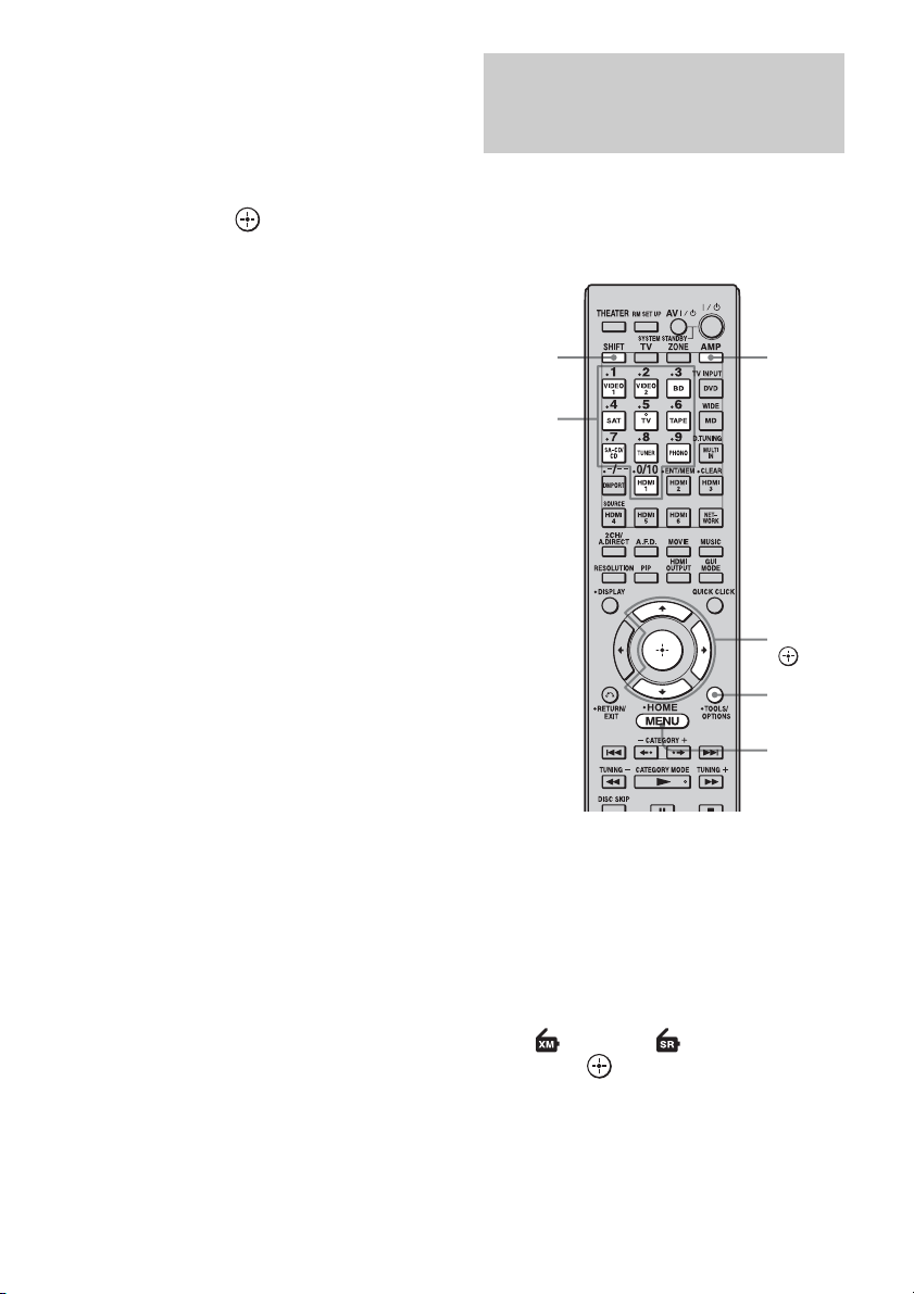
• (category name): You can select a
channel from one category.
When the “Preset Mode” screen is
displayed, press OPTIONS, then press V/
v repeatedly to select “Category Mode.”
5 Press V/v to select the channel,
then press .
The selected channel is being received.
The channel information is displayed on
the TV screen.
Selecting a channel by inputting
the channel number directly
(Direct Tuning)
Enter the channel number directly by using the
numeric buttons on the multifunction remote.
This operation cannot be performed using the
simple remote.
Note
When you select a channel in the “Category Mode,”
the channel you selected may not be the one in the
category you want. This is because one channel may
belong to more than one category.
SHIFT
Numeric
buttons
1 Press AMP.
The receiver can be operated using the
remote.
2 Press MENU.
The menu is displayed on the TV screen.
AMP
V/v/b,
OPTIONS
MENU
76
3 Press V/v repeatedly to select
“ XM” or “ SIRIUS,” then
press or b.
4 Press OPTIONS.
The option menu appears.
GB
Page 77

5 Press V/v to select “Direct
Tuning,” then press .
6 Press SHIFT, then press the
numeric buttons to enter the
channel number, then press
.
The selected channel is tune in.
Presetting satellite radio channels
You can select the channels you want directly
by presetting them using the preset numbers.
You can preset up to 30 XM Radio channels
and 30 SIRIUS Satellite Radio channels.
Tuning
V/v/b,
OPTIONS
MENU
1 Select a channel you want to
preset using Category Mode
(page 75) or Direct Tuning
(page 76).
2 Press OPTIONS.
The option menu appears.
3 Press V/v to select “Memory,”
then press .
The preset number selection screen
appears.
continued
77
GB
Page 78
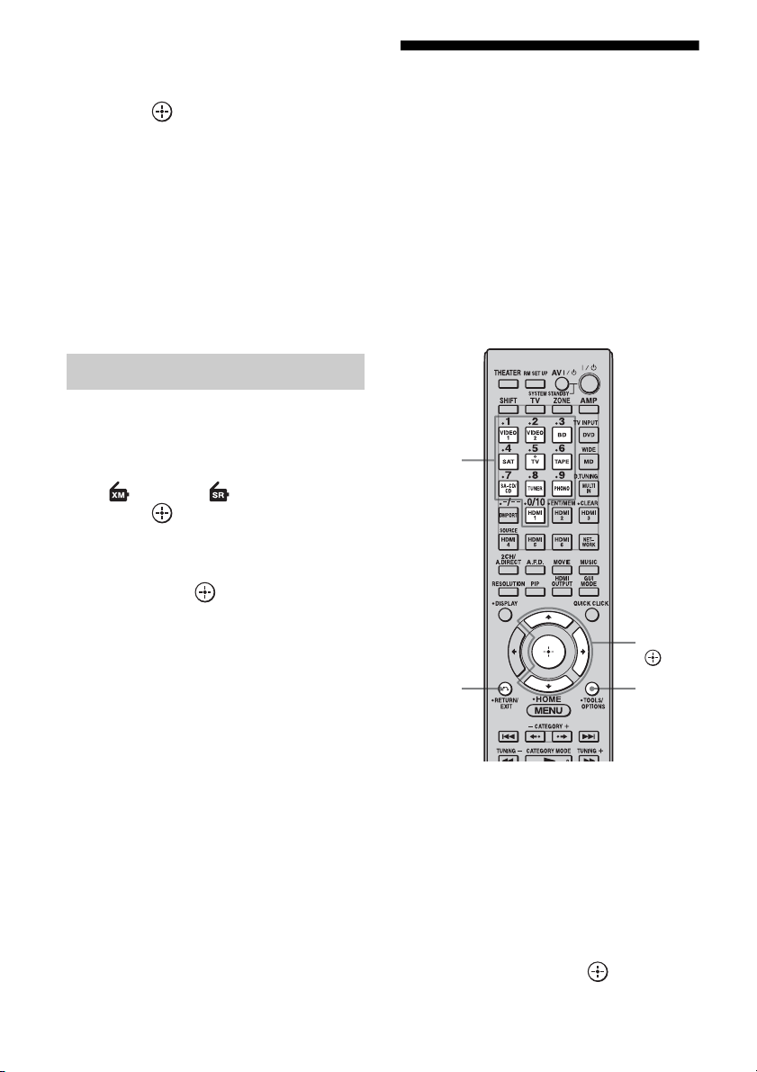
4 Press V/v repeatedly to select
the preset number you want to
use as the preset channel, then
press .
Preset channels from 1 to 30 are available,
and a default channel is preset for all the
preset channels when you purchase the
receiver.
The selected channel is registered as the
preset channel you selected in step 1.
5 Repeat steps 1 to 4 to preset
another channel.
You can store channels from 1 to 30.
Selecting preset channels
1 Press MENU.
The menu is displayed on the TV screen.
2 Press V/v repeatedly to select
“ XM” or “ SIRIUS,” then
press or b.
3 Press V/v to select the preset
number from the preset list,
then press .
You can select stored preset channels
from 1 to 30.
Notes
• The channel information you have preset may be
changed if XM Satellite Radio Inc. or SIRIUS
Satellite Radio Inc. change their channel
programming.
• When the “Category Mode” screen is displayed,
press OPTIONS, then press V/v to select “Preset
Mode.”
Restricting access to
specific channels
(Parental Lock) (SIRIUS only)
You can restrict access to certain channels
using your own lock code. The lock code is set
to “0000” as the default. Use the multifunction
remote for this operation. This operation
cannot be performed using the simple remote.
Change the lock code before you use this
function for the first time. See “To change the
lock code (Lock Code)” (page 79).
Numeric
buttons
V/v/b,
RETURN/
EXIT O
OPTIONS
1 Select a channel you want to
lock using Category Mode
(page 75) or Direct Tuning
(page 76).
78
2 Press OPTIONS.
The option menu appears.
3 Press V/v to select “Parental
Lock,” then press or b.
GB
Page 79

4 Press V/v repeatedly to select
“ON,” then press .
“Enter your 4-digit lock code.” appears.
To cancel the Parental Lock
Select a channel you want to unlock
1
using Direct Tuning (page 76).
5 Enter your 4-digit lock code
using the numeric buttons.
“The channel has been locked.” appears
and the Parental Lock is set.
To delete the numbers you have entered,
go back to step 2 by pressing RETURN/
EXIT O, and then repeat the procedure
above from step 2.
To change the lock code (Lock
Code)
Select any channel using Category
1
Mode (page 75) or Direct Tuning
(page 76).
2 Press OPTIONS.
The option menu appears.
3 Press V/v to select “Lock Code,” then
press .
“Enter your 4-digit lock code.” appears.
4 Enter your 4-digit lock code using the
numeric buttons.
“Enter a new lock code.” appears.
5 Enter a new 4-digit lock code using the
numeric buttons.
“To confirm, enter your new lock code
again.” appears.
2 Press OPTIONS.
The option menu appears.
3 Press V/v to select “Parental Lock,”
then press or b.
4 Press V/v repeatedly to select “OFF,”
then press .
“Enter your 4-digit lock code.” appears.
5 Enter your 4-digit lock code using the
numeric buttons.
“The channel has been unlocked.” appears
and the channel is unlocked.
Notes
• You can set only one lock code on the receiver. You
cannot set individual lock codes for each channel.
• When you select a channel using Category Mode,
locked channels are skipped.
• When the receiver is reset to the factory settings,
the lock code returns to the default (0000), but the
Parental Lock settings are not removed.
• You cannot preset locked channels. If you set the
Parental Lock for a preset channel, the preset
information for that channel returns to the default.
• You cannot set the Parental Lock for channel 0 or
channel 184.
Tuning
6 Reenter the new lock code with the
numeric buttons.
“The lock code has been changed.”
appears.
To listen to the locked channels
Select a locked channel you want to
1
listen to using Direct Tuning (page 76).
“The channel is locked. Enter your 4-digit
lock code.” appears.
2 Enter your 4-digit lock code using the
numeric buttons.
The channel is tuned in.
79
GB
Page 80

Message list
SIRIUS Satellite Radio message list
Message
appears
Antenna Error The antenna is not connected properly. Check the connection between the SiriusConnect
Acquiring Signal The receiving condition is not good. Try moving the antenna to another location. For
Call 888-539SIRI
Check Sirius
Tuner
Invalid Channel You have entered an invalid channel
Locked
Channel
Subscription
Updated
Updating
Channels
xx%
Completed
(xx are for
integers)
Firmware
Updating
–––– – There is no text information in the
Explanation Remedies
Home tuner and the antenna.
details about the antenna location, refer to the
instructions supplied with the SiriusConnect
Home tuner.
You have not subscribed for the selected
channel.
The SiriusConnect Home tuner is not
connected properly.
number.
The selected channel is locked. —
The subscription information has been
updated.
Channel information is being updated. —
The SiriusConnect Home tuner
firmware is being updated.
channel.
—
Check all the connections, and then turn the
system on again. Also make sure if the AC adaptor
supplied with the SiriusConnect Home tuner is
connected to a wall socket.
The channel to be tuned in is void due to the
change by the broadcast service, or the receiving
condition is not good.
—
—
This is not an error. The text information may not
be displayed depending on the system condition,
for example, right after the system has received a
channel.
80
GB
Page 81

XM Radio message list
Message
appears
Check Antenna The XM antenna is not connected to the
CH Unauthorized You selected an XM channel that is
No Signal The XM Mini-Tuner is not receiving the
Loading The XM Mini-Tuner is acquiring audio
Off Air You selected an XM channel is not
(space)–––– No artist name or song title is available
CH Unavailable The selected channel is not available.
Check XM Tuner The XM Mini-Tuner is not installed or
Explanation Remedies
XM Mini-Tuner Dock or the XM
antenna cable is damaged.
blocked or cannot be received with your
XM subscription package.
XM satellite signal. Something may be
blocking the XM antenna’s view of the
satellites or the antenna is not properly
aimed.
or program information from the XM
satellite signal. This message can also
occur in weak XM signal conditions.
Note that the receiver may not respond
to some buttons while this message is
displayed.
currently broadcasting.
for this selection.
The channel may have been reassigned
to a different channel number.
This message may occur initially with a
new radio or a radio that has not received
XM’s signal for an extended period.
not fully seated in the XM Mini-Tuner
Dock or the XM Mini-Tuner dock is not
connected to the receiver.
Check that the XM antenna is securely connected
to the XM Mini-Tuner Dock and check the
antenna cable for damage.
Replace the XM antenna if the cable is damaged.
Consult the latest channel guide at
www.xmradio.com for the current list of channels.
For information on receiving this channel, visit
www.xmradio.com or contact XM Satellite Radio
at 1-800-967-2346.
Check for antenna obstructions and reposition the
XM antenna to get better signal reception. Use the
Antenna Aiming option to optimize the antenna
position (page 75).
Refer to instructions supplied with the XM MiniTuner and Home Dock for antenna installation
information.
This message should disappear in a few seconds in
good signal conditions.
If you see this message often, reposition the XM
antenna for better signal reception.
Use the Antenna Aiming option to optimize the
antenna position (page 75).
Check back later; in the mean time, select another
channel.
No action required.
Consult the latest channel guide at
www.xmradio.com for the current list of channels.
For cases of a new radio or a radio that has not
received XM’s signal for an extended period,
allow the radio to receive the XM satellite signal
for at least 5 minutes and then try to select the
channel again.
Confirm the XM Mini-Tuner is fully seated in the
dock and check the XM Mini-Tuner dock cable is
connected to the receiver.
Tuning
81
GB
Page 82

Enjoying Surround Sound
Playing back with 2-channel sound
You can switch the output sound to 2-channel sound regardless of the recording formats of the
software you are using, the playback component connected, or the sound field settings of the
receiver.
2CH/
A.DIRECT
Press 2CH/A.DIRECT repeatedly to select the 2-channel sound mode of the
sound output you want.
2CH mode Effect
2ch Stereo The receiver outputs the sound from the front left/right speakers only. There is
2ch Analog Direct You can switch the audio of the selected input to 2 channel analog input. This
GB
82
no sound from the subwoofer.
Standard 2 channel stereo sources comp letely bypass the sound field processing
and multi-channel surround formats are downmixed to 2 channel.
function enables you to enjoy high quality analog sources.
When using this function, only the volume and front speaker balance can be
adjusted.
Page 83

Playing back with multi-channel surround
The Auto Format Direct (A.F.D.) mode allows you to listen to higher fidelity sound and select the
decoding mode for listening to a 2 channel stereo sound as multi-channel sound.
A.F.D.
V/v/b,
MENU
Press A.F.D. repeatedly to select the A.F.D. mode you want.
Enjoying Surround Sound
A.F.D. mode Multi-channel
audio after
decoding
A.F.D. Auto (Detecting
automatically)
Enhanced Surround – You can select the surround sound effect you want. For
Multi Stereo (Multi Stereo) Outputs 2 channel left/right signals from all speakers.
Effect
Presets the sound as it was recorded/encoded without
adding any surround effects.
details on available surround sound effects and how to
set one, see “Setting a multi-channel surround sound
effect” (page 84).
83
GB
Page 84

Setting a multi-channel
surround sound effect
1 Start playing a sound source
you want to listen to (CD, DVD,
etc.).
2 Press MENU.
The menu is displayed on the TV screen.
3 Press V/v repeatedly to select
“ Settings,” then press or
b.
The Settings menu list appears on the TV
screen.
4 Press V/v repeatedly to select
“Surround,” then press or b.
5 Press V/v repeatedly to select
“Enhanced Sur Mode,” then
press .
The menu for surround sound effect
appears.
6 Press V/v repeatedly to select
the Enhanced Sur Mode you
want, then press .
Enhanced Sur Mode Multi-channel
audio after
decoding
Pro Logic II* 5-channel signals Performs Dolby Pro Logic II mode decoding. A source
Pro Logic IIx* 7-channel signals Performs Dolby Pro Logic IIx mode decoding. A source
Neo:6 Cinema 7-channel signals Performs DTS Neo:6 Cinema mode decoding. A source
Neo:6 Music 7-channel signals Performs DTS Neo:6 Music mode decoding. A source
Neural-THX 7-channel signals Next generation of Neural-THX
* You can select “Pro Logic II” when there is no surround back speaker on the Speaker Pattern menu, or you
can select “Pro Logic IIx” when there is a surround back speaker. You cannot select both settings at the same
time.
Effect
recorded in 2 channel format is decoded into 5.1
channels. This setting is ideal for movies encoded in
Dolby Surround. In addition, this mode can reproduce
sound in 5.1 channel system for watching videos of
overdubbed or old movies.
recorded in 2 channel or 5.1 channel format is decoded
into 7.1 channels. This setting is ideal for movies
encoded in Dolby Surround. In addition, this mode can
reproduce sound in 7.1 channel system for watching
videos of overdubbed or old movies.
recorded in 2 channel format is decoded into 7 channels.
recorded in 2 channel format is decoded into 7 channels.
This setting is ideal for normal stereo sources such as
CDs.
®
to stereo enhancement processing and pure discrete 5.1
surround sound, now capable of full 360° 7.1 surround
sound playback from Neural-THX
content.
Surround. In addition
®
Surround encoded
84
GB
Page 85

Notes
• This function does not work when the multichannel input is selected.
• Neural-THX is not effective when DTS-HD
signals with a sampling frequency of 88.2 kHz and
higher are being received.
• This function does not work when Dolby TrueHD
signals with a sampling frequency of 176.4 kHz
and higher are being received.
• The beginning of the sound stream may be dropped
out when Neural-THX processing is turned on or
off.
Tips
• We usually recommend “A.F.D. Auto.”
• You can identify the encoding format of DVD
software, etc., by looking at the logo on the
package.
• Dolby Pro Logic IIx decoding is effective, when
2 channel or 5.1 channel signals are input.
• Neural-THX is effective when 2 channel or
5.1 channel signals are input.
Enjoying Surround Sound
85
GB
Page 86

Enjoying a surround effect for music
You can take advantage of surround sound simply by selecting one of the receiver’s preprogrammed sound fields. They bring the exciting and powerful sound of concert halls into your
home.
MUSIC
Press MUSIC repeatedly to select the surround effect you want for music.
Sound field Effect
D.Concert Hall A Uses 3D sound imaging to reproduce the sound characteristics of a concert hall,
D.Concert Hall B Uses 3D sound imaging to reproduce the sound characteristics of a concert hall,
Jazz Club Reproduces the acoustics of a jazz club.
Live Concert Reproduces the acoustics of a 300-seat live house.
Stadium Reproduces the feeling of a large open-air stadium.
Sports Reproduces the feeling of sports broadcasting.
Portable Audio Reproduces a clear enhanced sound image from your portable audio device.
GB
86
which simulates a large sound stage produced by reflectivity.
which simulates resonant and unique reverberative sound.
This mode is ideal for MP3 and other compressed music.
Page 87

To listen to music through headphones connected to the receiver
Sound field Effect
Headphone (2ch) This mode is selected automatically if you use headphones when “2ch Stereo”
mode or A.F.D. mode is selected. Standard 2 channel stereo sources completely
bypass the sound field processing and multi-channel surround formats are
downmixed to 2 channels.
Headphone (Direct) Outputs the analog signals without processing by the tone, sound field, etc.
Headphone (Multi) This mode is selected automatically if you use headphones when the multi-
channel input is selected. Outputs the front analog signals from the MULTI
CHANNEL INPUT jacks.
To turn off the surround effect for MUSIC
Press 2CH/A.DIRECT or A.F.D.
Notes
• The sound fields for music do not work when the
multi-channel input is selected.
• The sound fields for music do not work when DTSHD signals with a sampling frequency of 88.2 kHz
and higher are being received.
• The sound fields for music do not work when
Dolby TrueHD signals with a sampling frequency
of 176.4 kHz and higher are being received.
• If you set up the sound field during DTS 96/24
signal reception, the signal will be played back
only at 48 kHz.
• If you set up the sound field effect while the
receiver is receiving signals with a sampling
frequency of 88.2 kHz and higher, the signals will
always be played back at either 44.1 kHz or
48 kHz.
• When one of the sound fields for music is selected,
no sound is output from the subwoofer if all the
speakers are set to “LARGE” in the Speaker
settings menu. However, the sound will be output
from the subwoofer if the digital input signal
contains L.F.E. signals, or if the front or surround
speakers are set to “SMALL,” the sound field for
movie is selected, or “Portable Audio” is selected.
• If there is any noise present, the noise may be
different depending on the sound field you select.
Enjoying Surround Sound
87
GB
Page 88
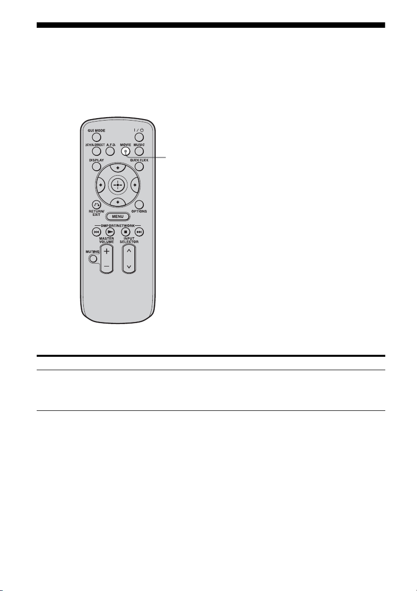
Enjoying a surround effect for movies
You can take advantage of surround sound simply by selecting the receiver’s preprogrammed HDD.C.S. (HD Digital Cinema Sound) sound field. It brings the exciting and powerful sound of movie
theaters into your home.
For details on HD-D.C.S. technology, see “Glossary” (page 180).
MOVIE
Press MOVIE.
Sound field Effect
HD-D.C.S. HD-D.C.S. can realize precisely sound effect on the movies watching through
Blu-ray and DVD software, etc. like how Movie Sound Designers’ intended to
be. You can select the Effect Type for HD-D.C.S. For details, see “Sound Field
Setup” (page 134).
To turn off the surround effect for MOVIE
Press 2CH/A.DIRECT or A.F.D.
GB
88
Page 89

Notes
• HD-D.C.S. does not work when the multi-channel
input is selected.
• HD-D.C.S. does not work when DTS-HD signals
with a sampling frequency of 88.2 kHz and higher
are being received.
• HD-D.C.S. does not work when Dolby TrueHD
signals with a sampling frequency of 176.4 kHz
and higher are being received.
• If you set up the sound field during DTS 96/24
signal reception, the signal will be played back
only at 48 kHz.
• If you set up the sound field effect while the
receiver is receiving signals with a sampling
frequency of 88.2 kHz and higher, the signals will
always be played back at either 44.1 kHz or
48 kHz.
• If there is any noise present, the noise may be
different depending on the sound field you select.
Enjoying Surround Sound
89
GB
Page 90

Digital audio formats supported by the receiver
Digital audio formats that this receiver can decode depend on digital audio input jacks for the
components connected.
This receiver supports the following audio formats.
Connection of the playback component and
the receiver
COAXIAL/OPTICAL HDMI
aa
aa
Audio format
Dolby Digital
Dolby Digital EX
Maximum number
of channels
5.1ch
6.1ch
Dolby Digital Plus
Dolby TrueHD
a)
a)
DTS
DTS-ES
DTS 96/24
DTS-HD
High Resolution Audio
DTS-HD
Master Audio
a) b)
7.1ch
7.1ch
5.1ch
6.1ch
5.1ch
a)
7.1ch
7.1ch
× a
× a
aa
aa
aa
× a
× a
90
GB
Page 91

DSD
Audio format
a)
Maximum number
of channels
5.1ch
Connection of the playback component and
the receiver
COAXIAL/OPTICAL HDMI
× a
Multi channel Linear PCM
a)
7.1ch
× a
a)Audio signals are output in another format if the playback component does not correspond to the format. For
details, refer to the operating instructions of the playback component.
b)Signals with a sampling frequency of 176.4 kHz and higher are played back at 96 kHz or 88.2 kHz.
Enjoying Surround Sound
91
GB
Page 92

Using Network Features
About the network functions of the receiver
• The home network function of the receiver
supports the DLNA (Digital Living Network
Alliance) standard.
You can also enjoy content (music, photos,
and videos) which have been stored on a
DLNA-compliant device (DLNA
CERTIFIED™ Products) that has an
authorized DLNA logo displayed on the
device.
• With an Internet connection, you can listen
to Rhapsody and SHOUTcast and upgrade
the firmware of the receiver. Rhapsody is
only available in the US.
About DLNA
DLNA (Digital Living Network Alliance) is a
standards organization made up of
manufacturers of various products, such as
computers, AV components, and mobile
computing devices which exchange content
(music, photos, and videos). DLNA decides
upon standards and publishes an authorized
logo to be displayed on devices which support
DLNA standards.
92
GB
Page 93

What you can do with the home network function
You can do the following using the network function of the receiver.
Playing back content (music, photos, and videos) on devices on a
home network
You can play back music, photos, and videos stored on other devices such as a computer on your
home network using this receiver (page 96).
Delivers content
Computer
Plays back content
STR-DA5500ES
Listening to Rhapsody or SHOUTcast over the Internet
You can listen to Rhapsody or SHOUTcast using the receiver (page 98, 101). Rhapsody is only
available in the US.
STR-DA5500ESInternet
Using Network Features
93
GB
Page 94

Other features
Changing the settings using a computer
You can change the settings of the receiver using a computer on your home network (page 103).
Computer
ES Utility application software
STR-DA5500ES
Firmware update
You can update the firmware of the receiver over the Internet.
A) Update the firmware directly over the Internet (page 146)
94
Internet
GB
STR-DA5500ES
Page 95

B) Update the firmware using a file downloaded from the Internet via a
computer (page 103)
Computer
Internet
ES Utility application software
STR-DA5500ES
Using Network Features
95
GB
Page 96

Enjoying content stored on the server
A server is a device which delivers content (music, photos, and videos) to a DLNA device on a
home network.
You can play back music, photos, and videos stored on the server using the receiver.
Computer STR-DA5500ES
3 Press V/v repeatedly to select
“Server,” then press .
The server list appears on the TV screen.
4 Press V/v and to select the
server which holds the content
V/v/B/b,
you want to play.
The content list appears on the TV screen.
MENU
1 Press MENU.
The menu is displayed on the TV screen.
2 Press V/v repeatedly to select
“ Music,” “ Photo,” or
“ Video,” then press or b.
GB
96
5 Press V/v/B/b and
repeatedly to select content
you want to play from the
content list.
The playback screen appears on the TV
screen, and content you selected is played
back.
Page 97

Using the multifunction remote
to play back content
You can enjoy content on the server by using
the following buttons on the multifunction
remote.
Press AMP to operate the receiver using the
remote.
Content
Type Music Photo Video
Remote
button
* This button may not work depending on the
connected server or the content type.
Nz z z
xz z z
Xz z z
>z z
.z z
Mz* z*
mz* z*
Selecting the playback mode
You can select the playback mode of the Music
category.
•All
Plays all the tracks repeatedly.
x Shuffle
Plays all the tracks in random order.
•Off
Deactivates the shuffle play mode.
•On
Activates the shuffle play mode.
Using Network Features
1 Press OPTIONS while listening
to the music content.
2 Press V/v repeatedly to select
“Repeat,” or “Shuffle,” then
press .
3 Press V/v repeatedly to select
the mode you want to select
from the following, then press
.
x Repeat
Plays one or all the tracks repeatedly.
•Off
Deactivates the repeat play mode.
•One
Plays one track repeatedly.
97
GB
Page 98

Listening to Rhapsody
You can enjoy the Rhapsody Digital Music
Service, without turning on a computer, by
connecting your receiver to the internet.
Rhapsody is only available in the US.
Rhapsody Digital Music Service
Play all the music you want with Rhapsody
Thousands of artists. Millions of songs.
Rhapsody is the critically-acclaimed digital
music service that gives you unlimited access
to a massive music catalog of millions of songs
and thousands of artists. You’ll also get
exclusive content, personalized
recommendations, DJ/ad-free listening on
“Rhapsody Channels” and more.
Try Rhapsody Now – Free 30 day Trial
For more information go to:
www.rhapsody.com/sonystr
®
Setting an account
Before using the Rhapsody Digital Music
Service, it is necessary to register an account
using your computer.
Refer to www.rhapsody.com/sonystr for
details.
Sign in using your account on the receiver.
1 Press MENU.
The menu is displayed on the TV screen.
2 Press V/v repeatedly to select
“ Settings,” then press or
b.
3 Press V/v repeatedly to select
“Network,” then press or b.
4 Press V/v repeatedly to select
“Rhapsody Account,” then
press .
The confirmation screen for account input
appears on the TV screen.
5 Press B/b repeatedly to select
“Yes,” then press .
The account input screen appears on the
TV screen.
98
V/v/B/b,
OPTIONS
MENU
6 Press V/v to select the user
name box, then press .
The soft keyboard appears on the TV
screen.
7 Press V/v/B/b and to select
a character one by one to enter
your user name.
8 Press V/v/B/b repeatedly to
select “Finish,” then press .
9 Press V/v repeatedly to select
the password box, then press
.
GB
Page 99

10Press V/v/B /b and to select
a character one by one to enter
your password.
3 Press V/v repeatedly to select
“Rhapsody Channels,” then
press .
11Press V/v/B /b repeatedly to
select “Finish,” then press .
12Press V/v repeatedly to select
“Finish,” then press .
Note
Repeat the process again from step 6 if the sign in
fails.
To delete an account
Press MENU.
1
The menu is displayed on the TV screen.
2 Press V/v repeatedly to select
“ Settings,” then press or b.
3 Press V/v repeatedly to select
“Network,” then press or b.
4 Press V/v repeatedly to select
“Rhapsody Account,” then press .
5 Press OPTIONS to select “Remove
Account,” then press .
6 Press B/b repeatedly to select “Yes,”
then press .
The user name and the password are
deleted.
Selecting the channel from the
Rhapsody Channels list
You can select the channel you want to listen
using the Rhapsody Channels list.
1 Press MENU.
The menu is displayed on the TV screen.
2 Press V/v repeatedly to select
“ Rhapsody,” then press
or b.
4 Press V/v/B/b repeatedly to
select the channel you want to
listen to, then press .
The reception screen appears on the TV
screen and the channel you selected is
received.
Note
You can listen to only the same channel in both the
main zone and the 2nd zone.
Priority is given to the channel which has most
recently been selected, even if other channel is
currently being selected in one of zones.
Using Network Features
Selecting the track using Music
Guide
The Music Guide displays a variety of music
selections to sample, including top tracks and
artists, and recommendations.
Select genre names, charts, and new releases
anywhere in the Music Guide pages to browse
more.
1 Press MENU.
The menu is displayed on the TV screen.
2 Press V/v repeatedly to select
“ Rhapsody,” then press
or b.
3 Press V/v repeatedly to select
“Rhapsody Music Guide,” then
press .
4 Press V/v repeatedly to select
“Genres,” “Charts,” “New
Releases,” or “Rhapsody
Recommends,” then press .
continued
99
GB
Page 100

5 Press V/v/B/b to select the
track you want to listen to from
the list, then press .
The playback screen appears on the TV
screen and the track you selected is
played back.
Note
You can listen to only the same track in both the
main zone and the 2nd zone.
Priority is given to the track which has most recently
been selected, even if other track is currently being
selected in one of zones.
Searching for a track, album, or
artist you want to listen to
You can search for a track, album, or artist
using the search function.
1 Press MENU.
The menu is displayed on the TV screen.
2 Press V/v repeatedly to select
“ Rhapsody,” then press
or b.
3 Press V/v repeatedly to select
“Search,” then press .
8 Press V/v/B/b repeatedly to
select the track you want to
listen to from the search result,
then press .
The playback screen appears on the TV
screen, and track you selected is played
back.
Note
You can listen to only the same track in both the
main zone and the 2nd zone.
Priority is given to the track which has most recently
been selected, even if other track is currently being
selected in one of zones.
Registering your favorite track,
album, or channel
You can register your favorite track, album, or
channel in “My Library” while playing back
the track or during reception.
You can select the track, album or channel that
you registered in “My Library” from “My
Artists,” “My Albums,” “My Genres,” “My
Tracks,” “My Playlists,” or “My Channels.”
1 Press OPTIONS while a track is
playing back or you are
selecting a channel.
4 Press V/v repeatedly to select
“Artists,” “Albums,” or
“Tracks” you want to search for,
then press .
The soft keyboard appears on the TV
screen.
5 Press V/v/B/b and to select
a character one by one to enter
the title or name you want to
search for.
6 Press V/v/B/b to select
“Finish,” then press .
Wait until the search result is displayed.
7 Press b to select the search
results.
GB
100
2 Press V/v repeatedly to select
“Add track to My Library,” “Add
album to My Library,” or “Add
channel to My Library,” then
press .
The track, album, or channel you chose
will be registered in “My Library.”
To remove a track, album, or
channel you registered
You can remove a track, album, or channel you
registered in “My Library.”
1 Press OPTIONS while a track is playing
back or you are selecting a channel.
 Loading...