

Sony STRD-560-Z, STRD-660-Z, STRDE-615, STRDE-715 Service manual
STR-D560Z/D660Z/DE615/DE715
SERVICE
Manufactured under license from Dolby Laboratories Licensing
Corporation.
“Dolby”, the double-D symbol a and “Pro Logic” are trademarks
of Dolby Laboratories Licensing Corporation.
MANUAL
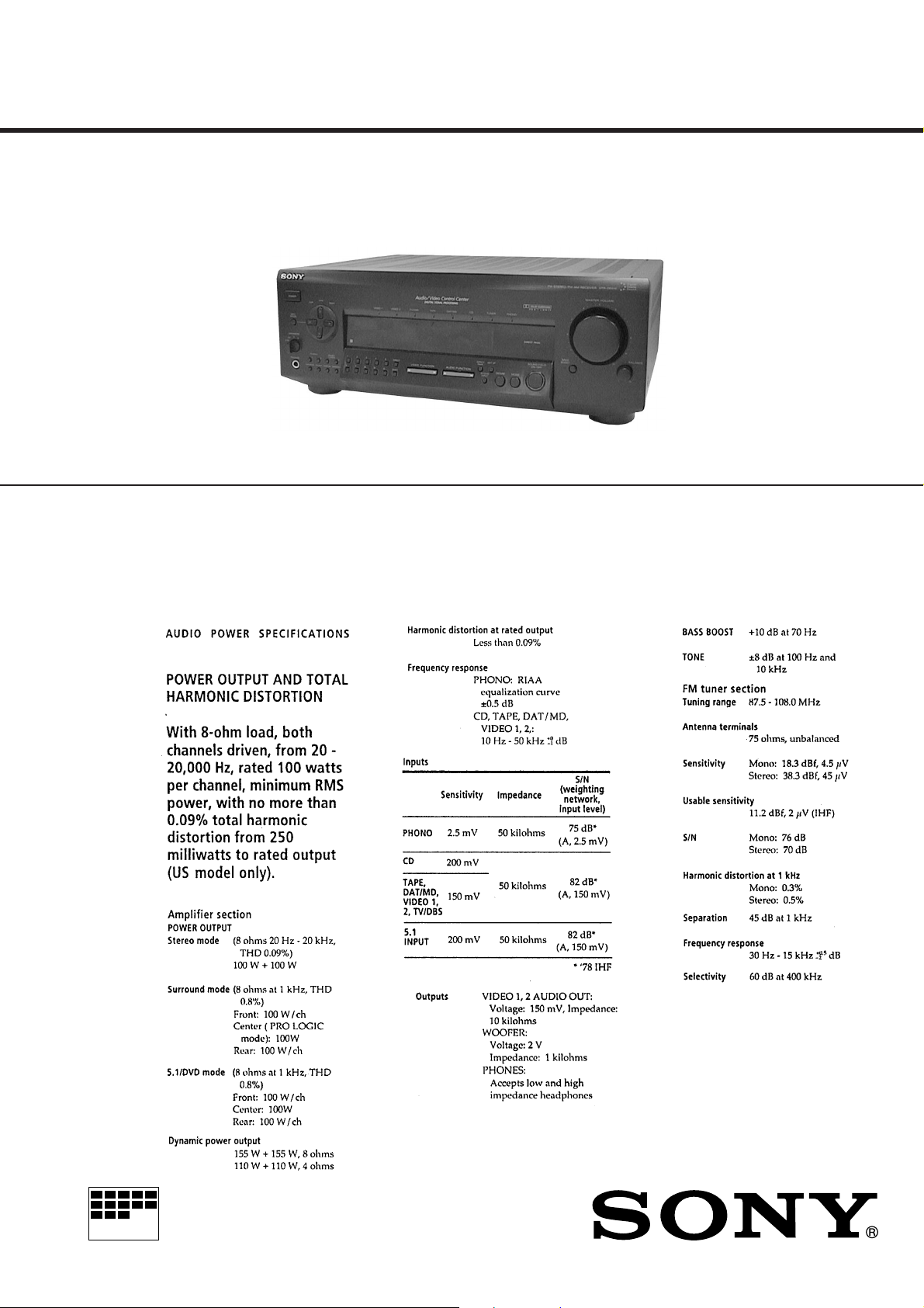
Photo : STR-DE615
SPECIFICATIONS
US Model
STR-D560Z/D660Z/DE615/DE715
Canadian Model
STR-DE615/DE715
Austr alian Model
STR-DE715
MICROFILM
– Continued on page 2 –
FM STEREO/FM-AM RECEIVER
TABLE OF CONTENTS
Specifications ........................................................................... 1
1.GENERAL
Location and Function of Controls .................................... 4
2. DIAGRAMS
2-1. IC Pin Functions ......................................................... 6
2-2. Circuit Boards Locations .......................................... 10
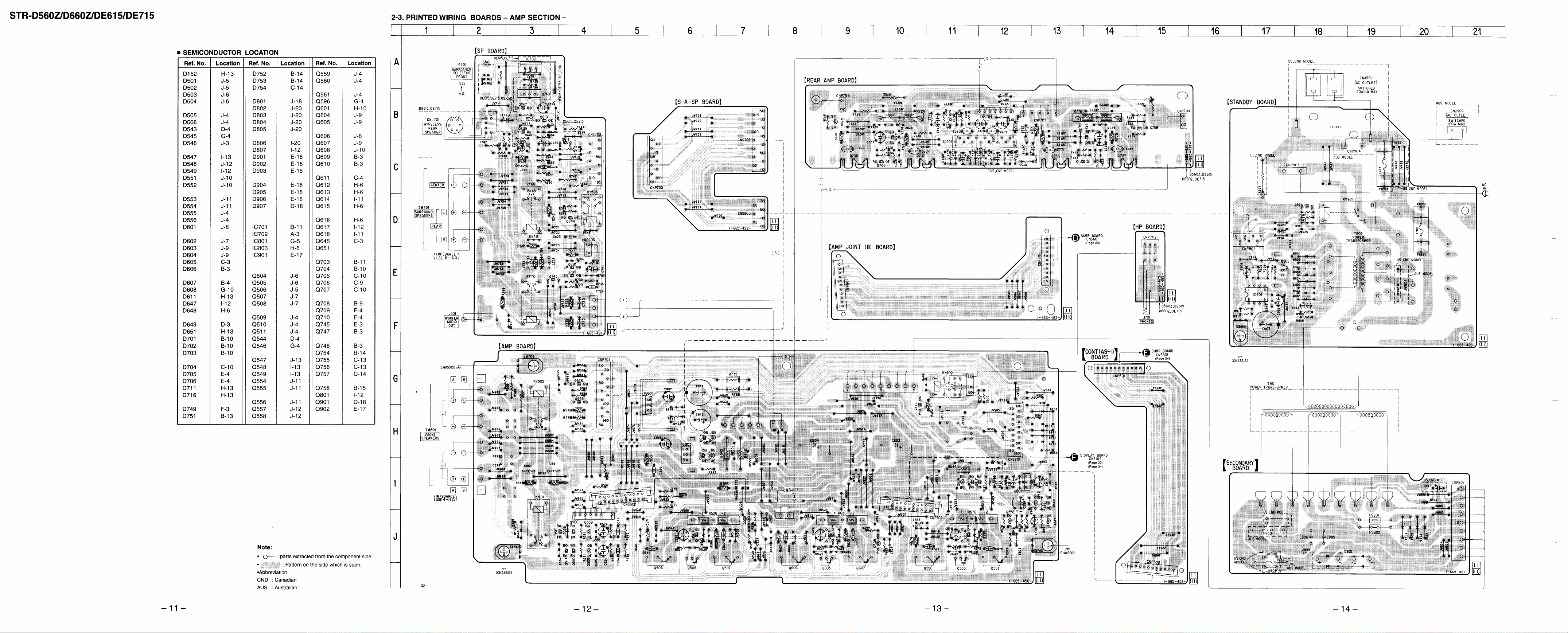
2-3. Printed Wiring Boards – AMP Section –.................. 11
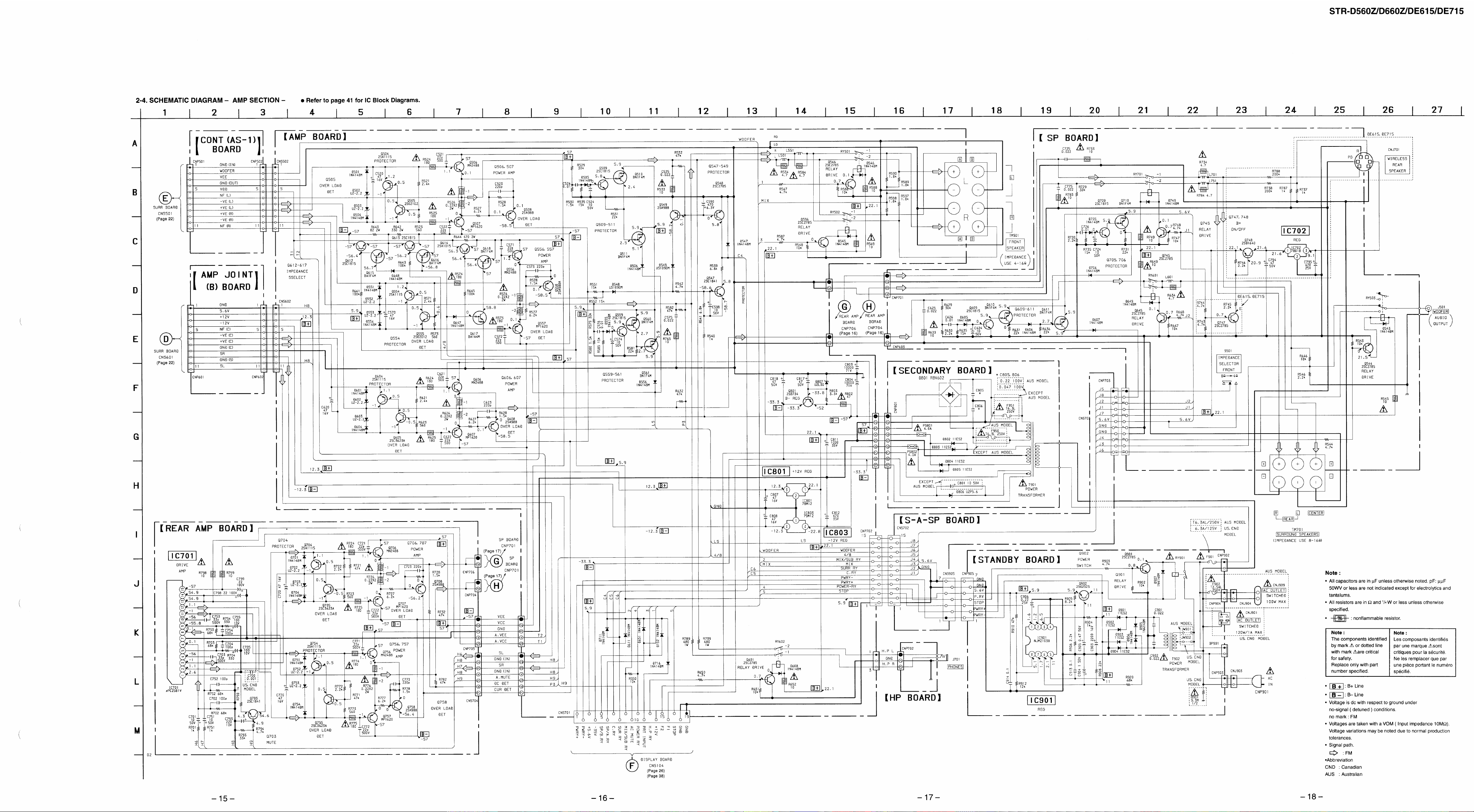
2-4. Schematic Diagram – AMP Section – ..................... 15
2-5. Schematic Diagram – Surround Section –............... 19
2-6. Printed Wiring Boards – Surround Section – ........... 23
2-7. Schematic Diagram
– Display Section (STR-D560Z/DE615) – .............. 26
2-8. Printed Wiring Boards
– Display Section (STR-D560Z/DE615) – .............. 29
2-9. Printed Wiring Boards
– Display Section (STR-D660Z/DE715) – .............. 33
2-10. Schematic Diagram
– Display Section (STR-D660Z/DE715) – .............. 37
3. EXPLODED VIEWS
3-1. Front Panel Section................................................... 44
3-2. Chassis Section ......................................................... 46
3-3. Back Panel Section ................................................... 47
4. ELECTRICAL PARTS LIST ........................................ 48
– 2 –
SAFETY CHECK-OUT
After correcting the original service problem, perform the following safety check before releasing the set to the customer :
Check the antenna terminals, metal trim, “metallized” knobs, screws,
and all other exposed metal parts for A C leakag e. Check leakage as
described below.
LEAKAGE TEST
The AC leakage from any exposed metal part to earth ground and
from all exposed metal parts to any exposed metal part having a
return to chassis, must not exceed 0.5mA (500 microampers).
Leakage current can be measured by any one of three methods.
1. A commercial leakage tester, such as the Simpson 229 or
RCAWT-540A. Follow the manufacturers’ instructions to use
these instruments.
2. A battery-operated AC milliammeter. The Data Precision 245
digital multimeter is suitable for this job.
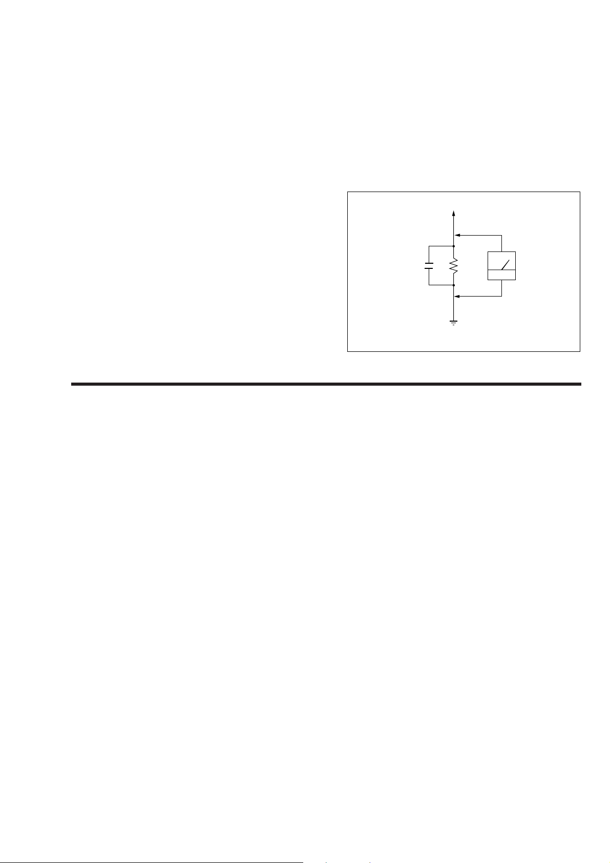
3. Measuring the voltage drop across a resistor by means of a V OM
or battery-operated AC voltmeter. The “ limit” indication is
0.75V , so analog meters must ha ve an accurate low-voltage scale.
The Simpson 250 and Sanwa SH-63Trd are examples of a passive VOM that is suitable. Nearly all battery operated digital
multimeters that have a 2V AC range are suitable. (See Fig. A)
To Exposed Metal Parts on Set
AC
0.15µF
Fig. A. Using an AC voltmeter to check AC leakage.
1.5k
Earth Ground
voltmeter
(0.75V)
SAFETY-RELATED COMPONENT WARNING!!
COMPONENTS IDENTIFIED BY MARK
MARK
! ON THE SCHEMATIC DIAGRAMS AND IN THE PARTS
LIST ARE CRITICAL TO SAFE OPERATION.
REPLACE THESE COMPONENTS WITH SONY PARTS WHOSE
PART NUMBERS APPEAR AS SHOWN IN THIS MANUAL OR IN
SUPPLEMENTS PUBLISHED BY SONY.
! OR DO TTED LINE WITH
ATTENTION AU COMPOSANT AYANT RAPPORT
À LA SÉCURITÉ!
LES COMPOSANTS IDENTIFIÉS P AR UNE MARQUE ! SUR LES
DIAGRAMMES SCHÉMA TIQUES ET LA LISTE DES PIÈCES SONT
CRITIQUES POUR LA SÉCURITÉ DE FONCTIONNEMENT. NE
REMPLACER CES COMPOSANTS QUE PAR DES PIÈCES SONY
DONT LES NUMÉROS SONT DONNÉS DANS CE MANUEL OU
DANS LES SUPPLÉMENTS PUBLIÉS PAR SONY.
– 3 –
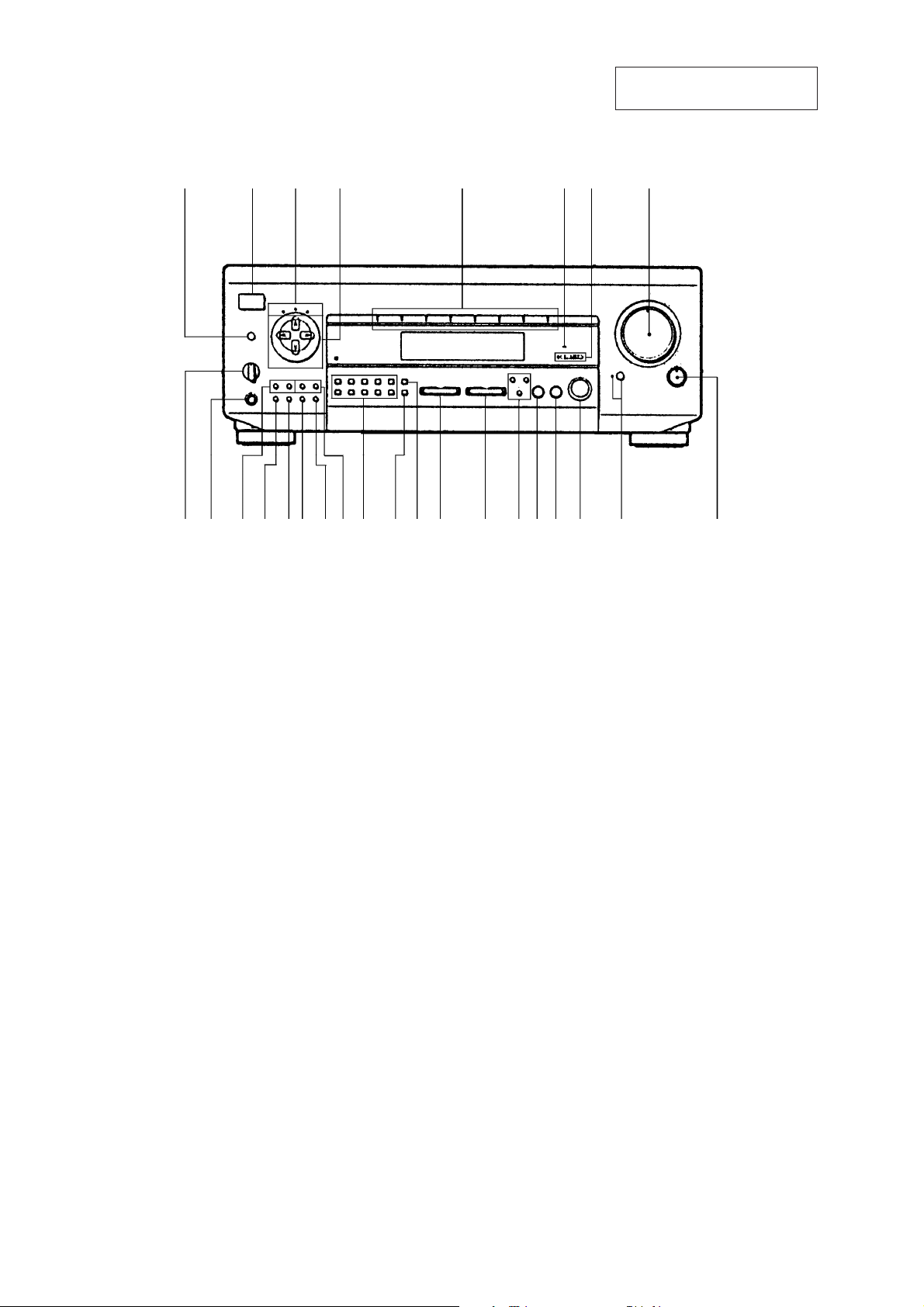
LOCATION AND FUNCTION OF CONTROLS
[FRONT PANEL]
1234 5 678
SECTION 1
GENERAL
This section is extracted from
instruction manual.
@¶@§ @∞@¢@£@™@¡@º!ª !•!¶!§ !∞ !¢!£!™!¡ 0 9
1DPC MODE button
2POWER switch
3SUR, TONE, INDEX indicators
4Digital processing control buttons
5Function indicators
6DIRECT PASS indicator
75.1 INPUT indicator
8MASTER VOLUME control
9BALANCE control
!ºBASS BOOST button/indicator
!¡SOUND FIELD ON/OFF button
!™MODE button
!£GENRE button
!¢DIRECT PASS, SET UP, 5.1/DVD INPUT buttons
!∞AUDIO FUNCTION buttons
!§VIDEO FUNCTION buttons
!¶DIRECT button
!•SHIFT button
!ªNumeric buttons
@ºPRESET TUNING +,– buttons
@¡MEMORY button
@™DISPLAY button
@£FM/AM button
@¢FM MODE button
@∞TUNING +,– buttons
@§PHONES jack
@¶SPEAKERS switch
– 4 –
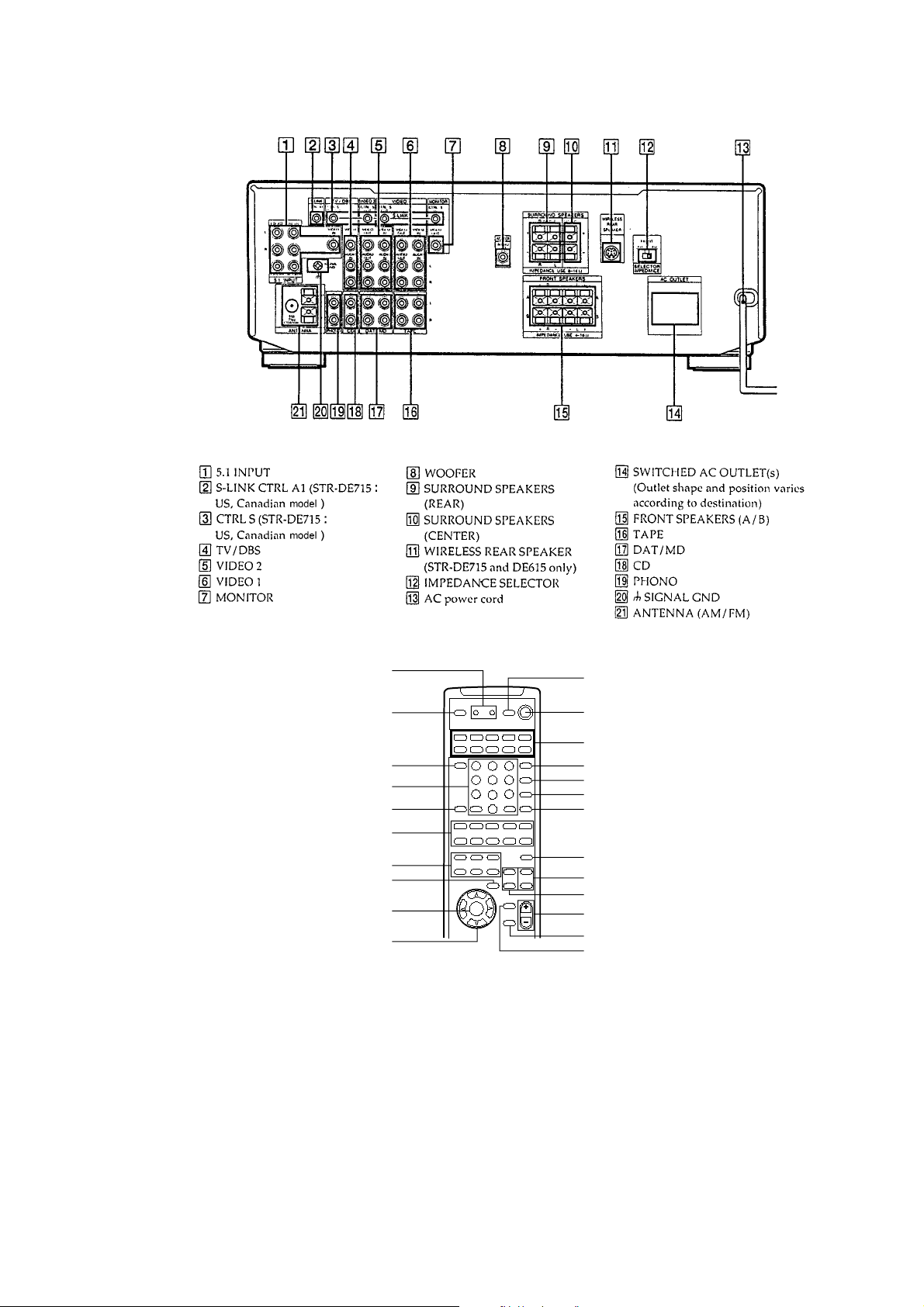
[REAR PANEL]
[REMOTE]
1
2
3
4
1 2 3
4 5 6
7
5
6
0 ) = +
(9
7
8
9
0
1 LEARN button/indicator
2 SLEEP button
3 TV CONTROL ON button
4 Numeric, ENTER buttons
5 BACKGROUND button
6 VCR/CD/DVD control buttons
7 SOUND FIELD buttons
8 DIRECT button
9 DPC MODE button
0 DIGITAL PROCESSING CONTROL buttons
!¡ VISUAL POWER button
!™ SYSTEM OFF button
!¡
!™
!£
!¢
!∞
9
8
0
p
rP
!§
!¶
!•
!ª
@º
@¡
@™
@£
!£ SYSTEM CONTROL/FUNCTION buttons
!¢ 5.1/INPUT button
!∞ TV/VIDEO button
!§ Direct TUNING button
!¶ CH/PRESET button
!• TEST TONE button
!ª CENTER LEVEL +, – buttons
@º REAR LEVEL +, – buttons
@¡ MASTER VOL buttons
@™ MUTING button
@£ BASS BOOST button
– 5 –
SECTION 2
DIAGRAMS
2-1. IC PIN FUNCTION
IC103 MB90673PF-G-196-BND (SYSTEM CONTROL) (STR-D660Z/DE715)
Pin No. Pin name I/O Description
1 AC MUTE O AC mute drive.
2 D. LAT O Data latch output.
3 T. LAT O Tuner function latch output.
4 S. CLK O Serial clock output.
5 S. DATA O Serial data output.
6 S. LAT O Serial latch output.
7 AUTO STOP O Tuner auto stop output.
8 T. MUTE O Tuner mute output.
9 STEREO I Stereo detect signal input.
10 IF DATA IN I IF data input.
11 VSS (D) – Ground.
12 V-A O Video switch control output.
13 V-B O Video switch control output.
14 RM INPUT I Remote control signal input.
15 V-E O Video switch control output.
16 V-INH – Not used (Open).
17 LED DATA O LED data output.
18 LED CLR O LED clock signal output.
19 S. POWER I Power switch input.
20 RX (SIN) – Not used (Fixed at “ L ” )
21 TX (SOUT) – Not used (Open).
22 BUSY – Not used (Open).
23 FL CLEAR O FL reset signal output.
24 FL DATA O FL data output.
25 FL CLK O FL clock output.
26 FL LAT O FL latch signal output.
27 ––––– – Not used (Ground).
28 VCC(A) – Analog power supply (+4.9V).
29 + AVR – Connect to VDD (+5.1V).
30 – AVR – Not used (Ground).
31 GND (D) – Ground.
32 AD KEY IN1 I Key input.
33 AD KEY IN2 I Key input.
34 VSS(D) – Ground.
35 AD KEY IN3 I Key input.
36 AD KEY IN4 I Key input.
37 AD KEY IN5 I Key input.
38 AD VERSION I Model select.
39 VOL + O Volume up control output.
40 VOL – O Volume down control output.
41 MODE0 – Not used (Fixed at “ H ” )
42 MODE1 – Not used (Fixed at “ H ” )
43 MODE2 – Not used (Ground).
44 STANDBY – Connect to VDD (+5.1V).
45 STOP O Power ON/OFF control output.
– 6 –
Pin No. Pin name I/O Description
46 LERNING LED – Not used (Open).
47 ––––– – Not used (Ground).
48 ––––– – Not used (Ground).
49 CTR A IN I Control S signal input (DE715 : US, Canadian model).
50 STANDBY LED – Not used (Open).
51 VOL LED O Volume LED drive.
52 S-OUT O Control S signal output (DE715 : US, Canadian model).
53 CTR A OUT O Control S signal output (DE715 : US, Canadian model).
54 VIDEO1 (M-BUS) O VIDEO1 control signal output.
55 VIDEO2 (M-BUS) O VIDEO2 control signal output.
56 TV (M-BUS) O TV control signal output.
57 –––– – Not used (Ground).
58 SP OFF IN I Speaker switch input.
59 SIGNAL IN – Not used (Ground).
60 –––– – Not used (Ground).
61 –––– – Not used (Ground).
62 RESET I Reset terminal.
63 VSS(D) – Ground.
64 XO O System clock (4.19MHZ).
65 XI I System clock (4.19MHZ).
66 VCC(D) – Digital power supply (+4.9V).
67 –––– – Not used (Ground).
68 POWER RY O Power relay drive.
69 BRIDGE RY – Power key input.
70 SUR RY O Surround relay drive.
71 CENTER RY O Center relay drive.
72 FRONT RY (H,P) O Front (Headphone) relay drive.
73 MIX/SUB RY O Woofer relay drive.
74 4/8 IN – Not used (Ground).
75 PROTECT IN I Protector operation input.
76 DIRECT PASS O Direct pass relay drive.
77 BASS BOOST O Bass boost ON/OFF control.
78 F/C/W MUTE O Front, Center, Woofer mute drive.
79 SL MUTE O Surround L-CH mute drive.
80 SR MUTE O Surround R-CH mute drive.
– 7 –
IC103 µPD780205GF-027-3BA (SYSTEM CONTROL) (STR-D560Z/DE615)
Pin No. Pin name I/O Description
1 –––– – Not used (Connect to VDD).
2 – 4 –––– – Not used (Connect to ground).
5 F/C/W. MUTE O Front, Center, Woofer mute drive.
6 SL MUTE O Surround L-CH mute drive.
7 SR MUTE O Surround R-CH mute drive.
8 AC MUTE O AC mute drive.
9 D LATCH O Data latch output.
10 RESET I Reset terminal.
11 X2 O System clock (4.19MHZ).
12 X1 I System clock (4.19MHZ).
13 VSS – Ground.
14 NP – Not used (Open).
15 –––– – Connect to reset terminal.
16 VDD – Power supply (+5V).
17 T LATCH O Tuner function latch output.
18 S CLOCK O Serial clock output.
19 S DATA O Serial data output.
20 S LATCH O Serial latch output.
21 AUDIO. STOP O Tuner auto stop output.
22 TUNER MUTE O Tuner mute output.
23 STEREO I Stereo detect signal input.
24 IF DATA IN I IF data input.
25 GND A/D – Ground.
26 SIRCS I Remote control signal input.
27 POWER KEY I Power key input.
28 VERSION I Model select input.
29 KEY 5 I Key input.
30 KEY 4 I Key input.
31 KEY 3 I Key input.
32 KEY 2 I Key input.
33 KEY 1 I Key input.
34 VDD A/D – Power supply (+5V).
35 VREF A/D I Reference voltage input.
36 V-A O Video switch control output.
37 V-B O Video switch control output.
38 V-E O Video switch control output.
39 STOP O Power ON/OFF control output.
40 VSS – Ground.
41 DIRECT PASS O Direct pass relay drive.
42 SUR RY O Surround relay drive.
43 CENTER RY O Center relay drive.
44 FRONT RY O Front relay drive.
45 MIX SUB RY O Woofer relay drive.
– 8 –
Pin No. Pin name I/O Description
46 VDD – Power supply (+5V).
47 PROTECTOR IN I Protector operation input.
48 POWER RY O Power relay drive.
49 BASS BOOST O Bass boost ON/OFF control.
50 SP OFF I Speaker switch input.
51 VOL – O Volume down control output.
52 VOL + O Volume up control output.
53 VOL LED O Volume LED drive.
54 STANDBY LED – Not used (Open).
55 ––––– – Not used (Open).
56 BASS BOOST LED O BASS BOOST LED drive.
57 5.1 INPUT LED O 5.1 INPUT LED drive.
58 DIRECT PASS LED O DIRECT PASS LED drive.
59 SUR LED O SUR LED drive.
60 TONE LED O TONE LED drive.
61 VIDEO 1 LED O VIDEO 1 LED drive.
62 INDEX LED O INDEX LED drive.
63 PHONO LED O PHONO LED drive.
64 TUNER LED O TUNER LED drive.
65 DAT MD LED O DAT/MD LED drive.
66 CD LED O CD LED drive.
67 TAPE LED O TAPE LED drive.
68 TV/DBS LED O TV/DBS LED drive.
69 VIDEO2 LED O VIDEO2 LED drive.
70 – 78 P1 – P9 O FL segment drive.
79 V LOARD – FL power supply (– 35V).
80 – 87 P10 – P17 O FL segment drive.
88 – 100 G1 – G13 O FL segment drive.
– 9 –
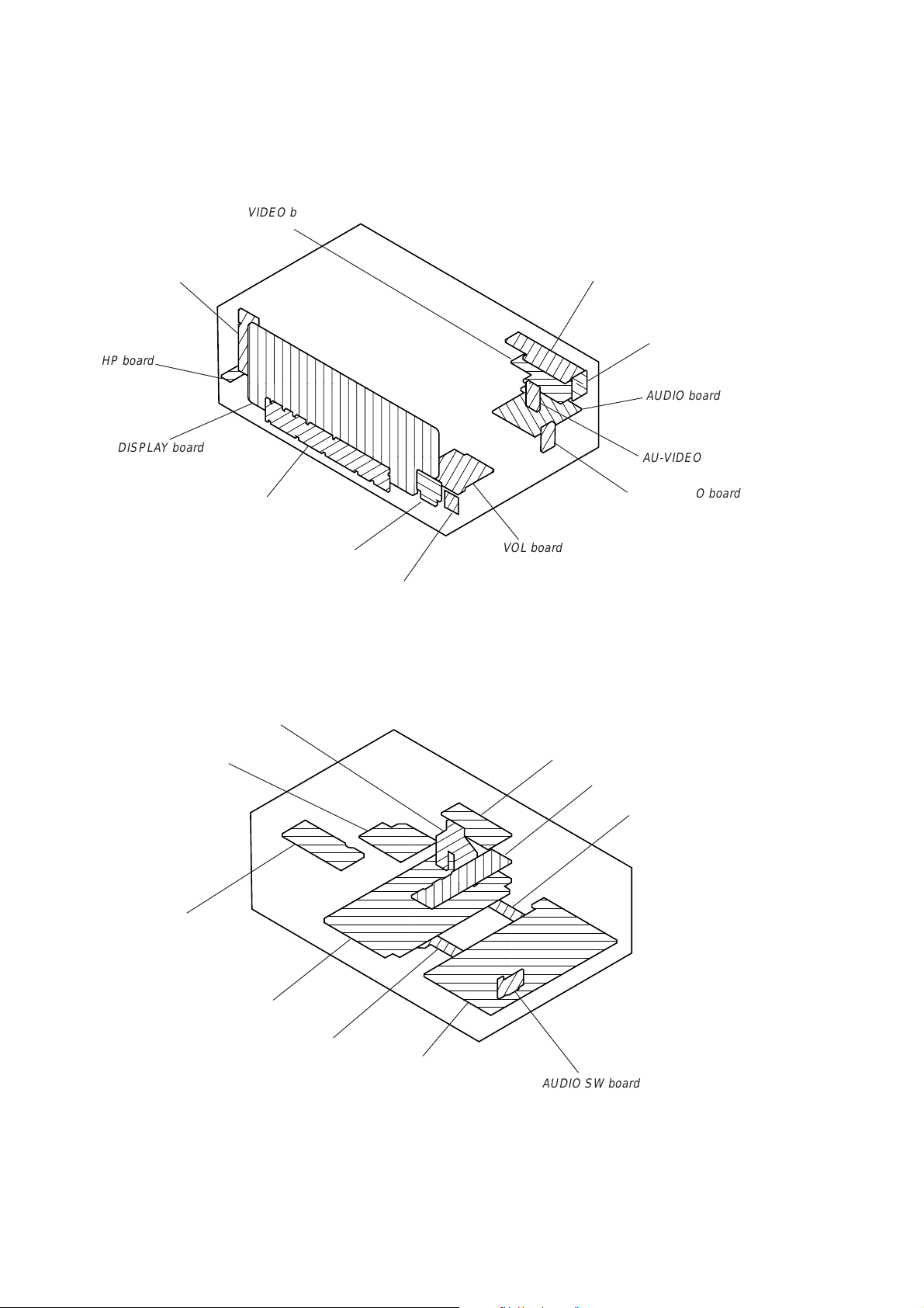
2-2. CIRCUIT BOARDS LOCATIONS
VIDEO board
SP SW board
HP board
DISPLAY board
SW board
S-A-SP board
L. B. SW board
BALANCE board
CTRL-A board (DE715 : US, Canadian model)
5.1 IN board
AUDIO board
AU-VIDEO board
SURR AUDIO board
VOL board
STANDBY board
SECONDARY board
SP board
REAR AMP board
AMP JOINT (B) board
AMP board
CONT (AS-1) board
SURR board
AUDIO SW board
– 10 –
 Loading...