

Page 1

FMSteiw/FM-AM
Receiver
3-753-197-21 (3) Tf,i A
Operating Instructions
STR-AV770X
1991 by Sony Corporation
Page 2
T63A
Warning
WARNING
To prevent fire or shock hazard, do not expose the
unit to rain or moisture.
CAUTION
RISK O F ELEC TRIC S HOCK
DO NOT OPEN
CAUTION: TO REDUCE THE RISK OF ELECTRIC SHOCK,
DO NOT REMOVE COVER (OR BACK).
NO USER-SERVICEABLE PARTS INSIDE.
REFER SERVICING TO QUALIFIED SERVICE PERSONNEL.
This symbol Is intended to alert the user to
the presence of uninsulated "dangerous
voltage" within the product's enclosure that
may be of sufficient magnitude to constitute
a risk of electric shock to persons.
This symbol is intended to alert the user to
the presence of important operating and
maintenance (servicing) instructions in the
literature accompanying the appliance.
For the customers in Canada
CAUTION
TO PREVENT ELECTRIC SHOCK, DO NOT USE THIS
POLARIZED AC PLUG WITH AN EXTENSION CORD,
RECEPTACLE OR OTHER OUTLET UNLESS THE
BLADES CAN BE FULLY INSERTED TO PREVENT
BLADE EXPOSURE.
Note to CATV system installer
This reminder is provided to call the CATV system
installer's attention to Article 820-22 of the NEC that
provides guidelines for proper grounding and, in
particular, specifies that the cable ground shall be
connected to the grounding system of the building, as
close to the point of cable entry as practical.
Owner's Record
The model number is located on the rear exterior and serial
number is on the rear. Record the serial number in the
space provided below. Refer to these numbers whenever
you call upon your Sony dealer regarding this product.
Model No^ Serial No.
Page 3

Table of Contents
Outline......................................................................................................................................4
Precautions...............................................................................................................................4
installing....................................................................................................................................5
Connections..............................................................................................................................6
Getting Started
Parts identification....................................................................................................................10
Audio adjustment.....................................................................................................................12
Selecting a program source....................................................................................................13
Basic operation
Radio reception.......................................................................................................................14
Notes on installation............................................................................................................5
Loading the remote commander with batteries.................................................................... 5
Notes on connections..........................................................................................................6
Connecting audio equipment.............................................................................................. 6
Connecting video equipment...............................................................................................7
Connecting the FM antenna................................................................................................8
Connecting the AM antenna................................................................................................8
Connecting the antenna ground..........................................................................................8
Connecting speaker systems..............................................................................................9
Connecting the AC power................................................................................................... 9
Front panel........................................................................................................................10
Remote commander RM-S103
Adjusting volume................................................................................................................12
Adjusting tone quality......................................................................................................... 12
Adjusting left and right sound balance
Reinforcing the bass...........................................................................................................12
Selecting the speaker system............................................................................................ 12
Labeling the program sources............................................................................................13
Tuning in a station directly — Direct tuning..........................................................................14
Scanning stations automatically — Auto tuning
Presetting stations — Station preset
Tuning in a preset station — Preset tuning.......................................................................... 17
Labeling the preset stations — Index input
Selecting a station among the preset stations having the index name
— Index tuning................................................................................................................. 19
Receiving FM simulcast TV programs...............................................................................19
..........................................................................................
...............................................................................
..................................................................
..................................................................................
.........................................................................
11
12
15
16
18
T63A
Appendix
Quick Reference
Audio recording........................................................................................................................20
Recording on an audio tape deck or DAT deck..................................................................20
Tape dubbing.................................................................................................................... 20
Video recording........................................................................................................................21
Video tape editing.............................................................................................................21
Adding new sound on a video tape during video editing...................................................21
Obtaining the surround effect..................................................................................................22
Available types of effects...................................................................................................22
Adjusting the input level for Dolby surround system
Listening with surround effect........................................................................................... 22
Specifications..........................................................................................................................23
Troubleshooting guide............................................................................................................. 24
Quick reference........................................................................................................................26
.........................................................
22
Page 4
T63
T63A
The STR-AV770X is a FM Stereo/FM-AM receiver and
audio/video control center.
You can enjoy various audio/video program sources with
this unit.
TV/video programs
• You can enjoy TV or CATV programs with FM simulcast.
• Sounds from various audio program sources can be
added on video tapes during editing.
Tuner
• Precise tuning is ensured by a quartz lock digital
synthesizer.
• Station Index system allows you to tune into a station
quickly.
Remote control
• The supplied remote commander allows you to remotely
control both the unit and the equipment connected to
the unit.
Precautions
Display
• The frequency of each tuned-in broadcast station is
displayed.
• The current selection/operation is displayed to clearly
indicate what is taking place.
Surround sound system
This unit incorporates all of 3 types of surround effect.
• nniooLBYsuiiRouNol * — expands sound just like listening
to it in a movie theater.
• Hall Surround-provides reverberation effect that is
produced in a large concert hall.
• Simulated Surround-gives the feeling of width and
thickness to monaural sound of old movie program, etc.
On safety
• Before operating the unit, be sure that the operating
voltage of your unit is identical with that of your local
power supply.
• Should any solid object or liquid fali into the cabinet,
unplug the unit and have it checked by qualified
personnel before operating it any further,
• Unplug the unit from the wall outlet if it is not to be used
for an extended period of time. To disconnect the cord,
pull it out by grasping the plug. Never pull the cord
itself.
• One blade of the plug is wider than the other for the
purpose of safety and will fit into the power outlet only
one way. If you are unable to insert the plug fully into the
outlet, contact your dealer.
On operation
• Before making program source connections, be sure to
turn the power switch off and unplug the unit.
On cleaning the cabinet
Clean the cabinet, panel and controls with a soft cloth
lightly moistened with mild detergent solution. Do not use
any type of abrasive pad, scouring powder, or solvent such
as alcohol or benzine.
For the customers in the U.S.A.
For detailed safety precautions, see the “IMPORTANT
SAFEGUARDS" leaflet.
If you have any question or problem concerning your unit,
please consult your nearest Sony dealer.
Manufactured under license from Dolby Laboratories Licensing
Corporation. Additionally licensed under one or more of the
following patents; U.S. numbers 3,632,886, 3,746,792, and
3,959,590. Canadian numbers 1,004,603 and 1,037,877.
“DOLBY" and the double-D symbol CE are trademarks of Dolby
Laboratories Licensing Corporation.
Page 5
Installing
Notes on Installation
To prevent internal heat buildup in the unit,
place the unit in a location with adequate air circulation.
Do not install the unit:
— near heat sources such as radiators or air ducts.
— in a place subject to direct sunlight, excessive dust, mechanical vibration or shock.
Do not place anything on top of the cabinet.
The top ventilation holes must be unobstructed for the proper operation of the unit and to prolong the life of its components.
Do not throw away the carton and packing material!
It will be an ideal container when transporting the system for repair work, etc.
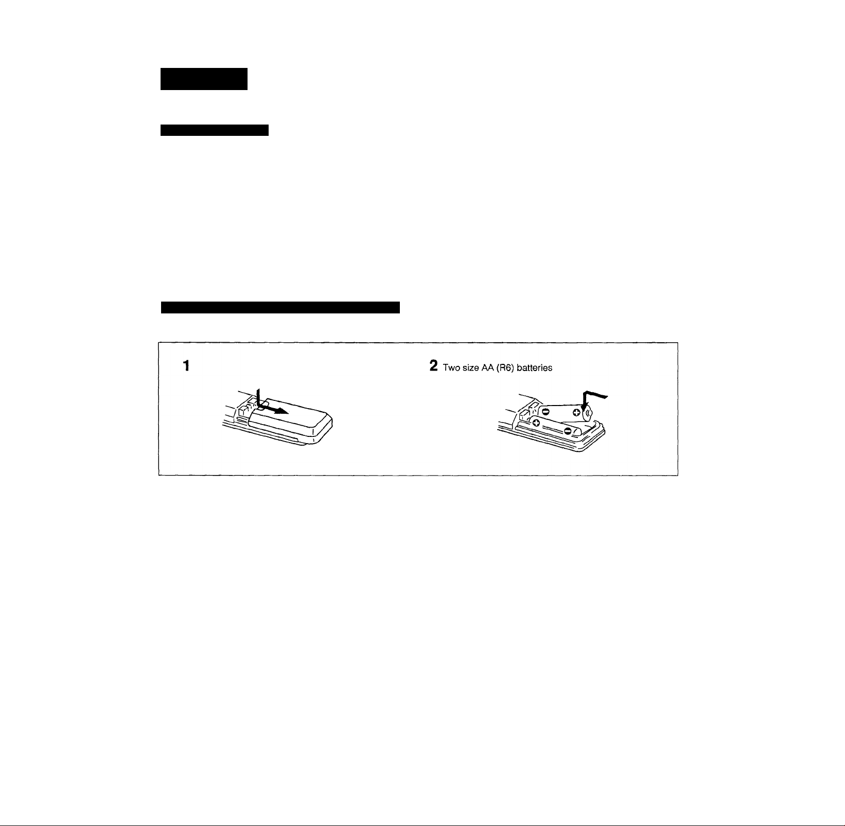
Loading the Remote Commander with Batteries
Before operating remote commander, install the batteries as shown.
T63A
To avoid damage caused by battery leakage and
corrosion
When the commander will not be used for a long time,
remove the batteries.
Battery life
Normal operation can be expected about a half year using
Sony SUM-3 (NS), and a year using Sony AM-3 (NW)
alkaline batteries.
When the batteries are run down, the remote commander
will not operate the unit. In this case, replace batteries with
new ones.
Changing the AM tuning interval
The AM tuning interval is preset to 10 kHz. To use the
receiver where the frequency allocation system is based
on a 9 kHz interval, make the following adjustments.
1 Turn on the power and tune in any AM station.
2 Turn off the power.
3 Press the POWER button while pressing the “+"
PRESET TUNING button.
To reset the AM tuning interval, repeat the above steps.
Caution
When the Interval Is changed, all preset stations which you have
memorized will be erased. After changing the interval, be sure to
preset the stations again.
Page 6
T63A
Connections
Notes on Connections
Do not connect the power cord to an AC outlet nor
press the POWER switch before accomplishing all other
connections.
The cable connectors should be fully Inserted into the
jacks. Loose connection may cause hum and noise.
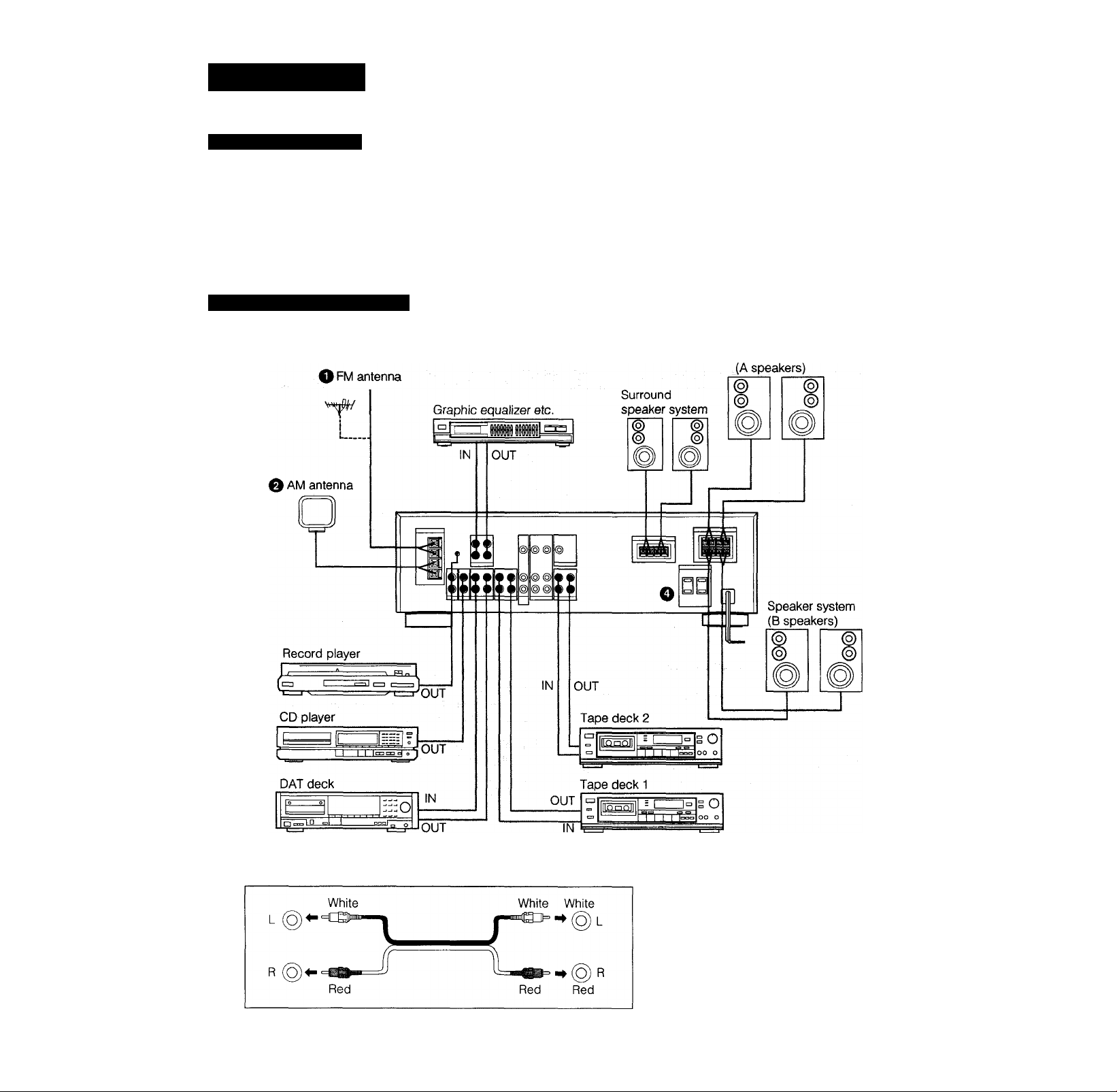
Connecting Audio Equipment
Jacks and plugs of the connecting cord are colorcoded as follows;
Red jacks and plugs: For the right channel of audio
signals
White jacks and plugs: For the left channel of audio
signals
Yellow jacks and plugs: For video signals
O Speaker system
6
Page 7
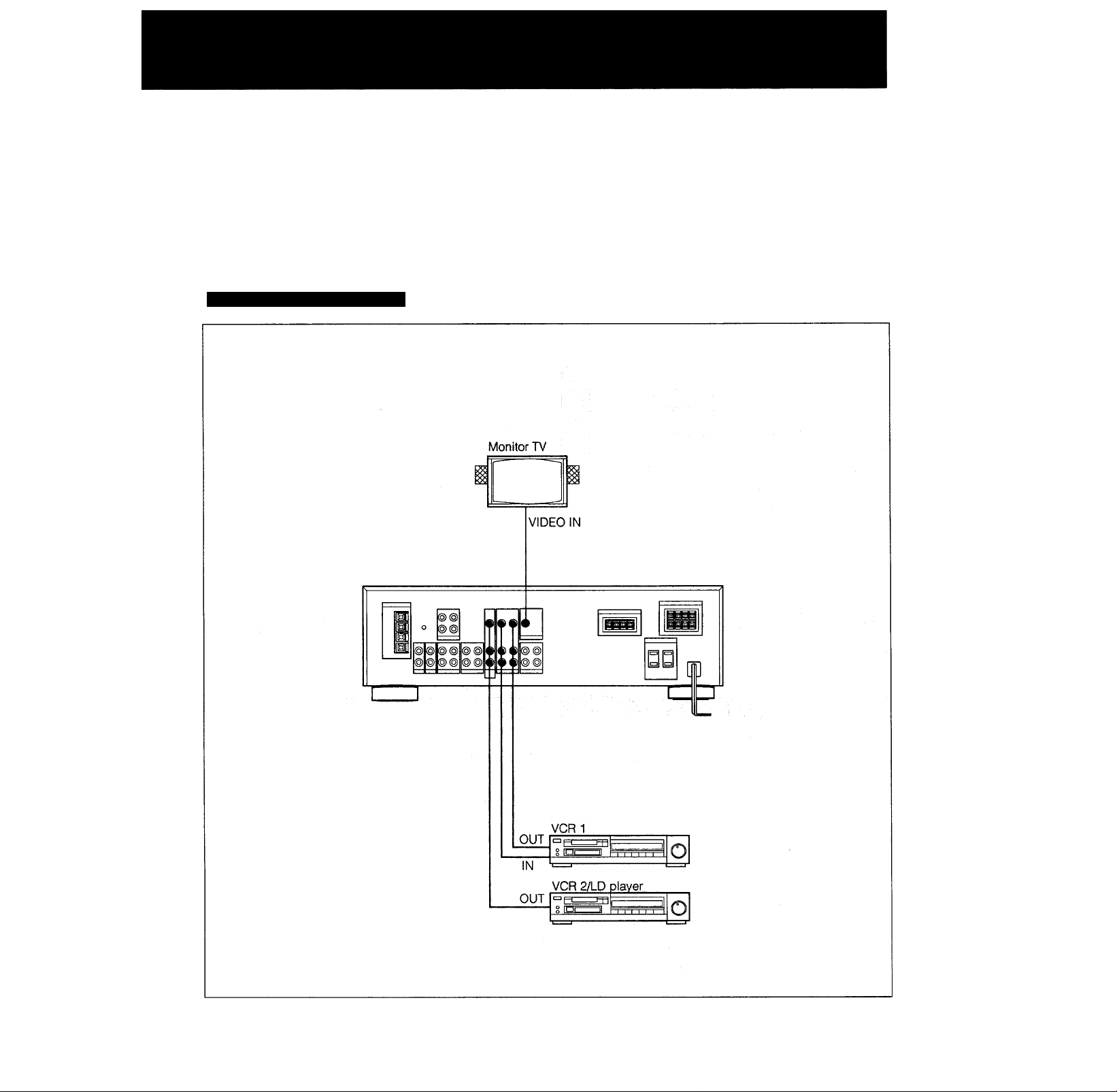
Connecting Video Equipment
T63A
7
Page 8
T63 A
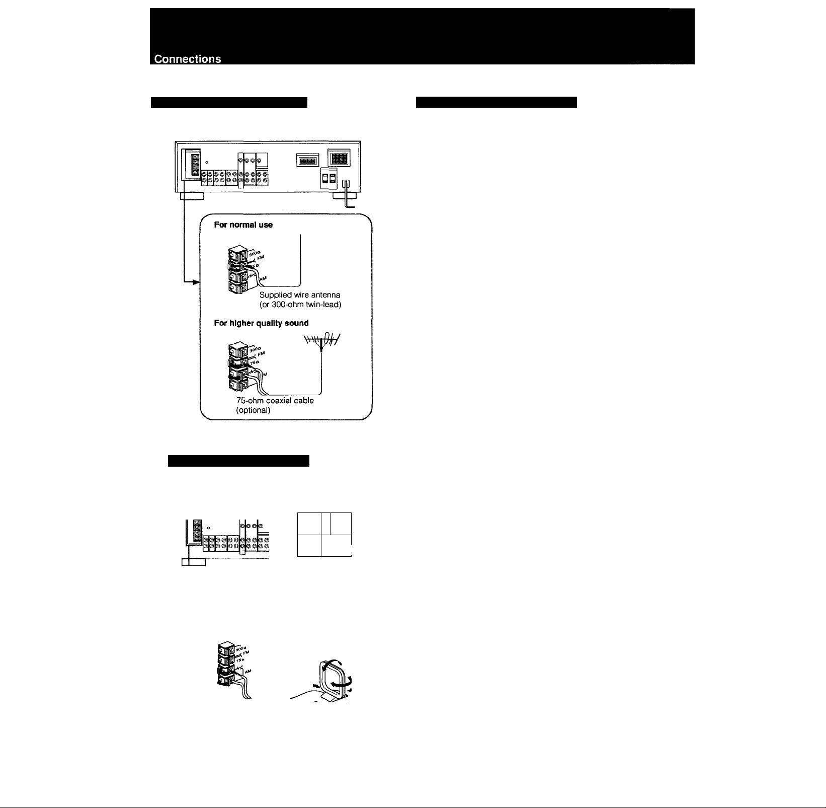
® Connecting the FM Antenna
Connecting the Antenna Ground
To prevent hum, connect the ground wire to ANTENNA
ground terminal ( At).
When an outdoor antenna is installed, be sure to connect
the ground wire for lightning protection.
Connecting the AM Antenna
■
qp
Adjust the
direction.
Supplied loop
antenna
For areas with difficult AM reception
In areas with troubled reception, connect a 6 to 15-meter
(20 to 50-foot) insulated wire to the AM antenna terminal.
Extend this out of doors if possible, keeping the greater
portion horizontal.
(There is no need to disconnect the supplied antenna.)
To prevent hum
Connect the ground wire to ANTENNA ground terminal {A-).
When an outdoor antenna is installed, be sure to connect
the ground wire for lightning protection.
8
Page 9
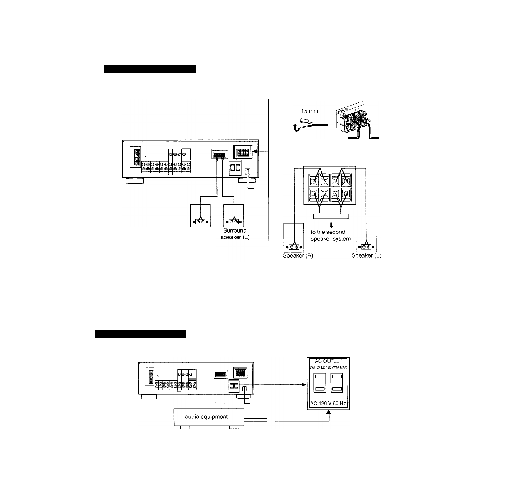
Connecting Speaker Systems
Surround
speaker (R)
Speaker impedance and power capability
This receiver is designed to work best with speakers having nominal impedance from 8 to 16 ohms. Be sure to use a speaker system with
adequate nominal impedance and power handling capabilities.
@ Connecting the AC Power
Caution
Be careful that the total power consumption of each equipment connected to the outlets on the receiver does not exceed 120 watts.
Do not connect electrical home appliances such as an electric iron, fan, TV, or other high-wattage equipment to these outlets.
Page 10

T63A
Parts Identification
Front Panel
E POWER switch
[H SHIFT button
[3] Remote control sensor
d] Numeric buttons
[5] Display window
S] MEMORY button
[U CURSOR MODE indicators
[U FM MODE button
[E FM/AM button
Bo] PRESET TUNING +/- buttons
M INDEX SELECT/ TUNING +/- buttons
M TUNING DIRECT button
|15| VOLUME control
[m MUTING switch and indicator
GZl INPUT BALANCE control
m BALANCE control
Bl BASS/TREBLE TONE controls
DBFB (Dynamic Bass Feed Back) button
HH CURSOR MODE operation buttons
H SURROUND MODE selector
M SURROUND ON/OFF button
M EDIT AUDIO button
mi CURSOR MODE switch
Function selectors and TAPE 2 MONITOR indicator
M TUNING LEVEL button
M DISPLAY mode button (FREQ/INDEX)
10
Hz] HEADPHONES jack
HU SPEAKERS selector
Page 11

Remote Commander RM-S103
lU POWER button
[2] DBFB button (page 12)
[3] TUNER PRESET +/- and SHIFT buttons
(page 16 and 17)
S VOLUME +/- buttons
[5] SURROUND button (page 22)
[U MUTING button (page 12)
[H CD player operation buttons*
D. (disc) SKIP: When your CD player is equipped with a
multi-disc changer, use this button to select loaded
disc.
CD ►; Selects the CD function and starts CD playback.
IS DECK B operation buttons* (also for single tape deck)
DECK B ◄/►; Select tape function and start tape
playback on deck B.
I
DECK A operation buttons*
DECK A ◄/►: Select tape function and start tape
playback on deck A.
I Function seiect buttons
These buttons control Sony audio components.
11
Page 12

Audio Adjustment
Adjusting volume
To adjust volume
Turn VOLUME.
To reduce the sound to a low level temporarily (- 20 dB
attenuation)
Press MUTING.
Press again to restore the same listening level as before.
Adjusting Tone Quality
BASS - TONE - TREBLE
*10 +10 -10 +10
Adjusting Left and Right Sound Balance
Reinforcing the Bass
Adjust BASS or TREBLE for the optimum sound.
Adjust BALANCE to correct stereo imaging, when the
speaker position is not symmetricai.
Press DBFB (Dynamic Bass Feed Back) so that DBFB ON
appears on the display.
Press again to turn off the effect so that DBFB OFF
appears on the dispiay.
Selecting the Speaker System
12
To drive speaker system A: Set SPEAKERS to A.
To drive speaker system B: Set SPEAKERS to B.
To drive both speaker systems A and B: Set SPEAKERS to
A + B.
For headphone listening: Connect headphones to
HEADPHONES and set SPEAKERS to OFF,
IMPORTANT
Speaker systems A and B are series connected. No sound
can be heard if the SPEAKERS selector is set to A + B
when only one speaker system is connected.
Page 13

Selecting a Program Source
CD player |
Tape deck
DAT
VCR
I LD player
1 Select the program source.
Labeling the Program sources
You can create the desired name (up to 11 characters) for
the functions except TUNER.
1 Select the program source.
FUNCTION selector to be
pressed
Phono record
Radio Broadcast
Compact disc
DAT programs
Taped programs
Video programs
PHONO
TUNER
CD
DAT
TAPE 1, TAPE 2 MONITOR
VIDEO 1, VIDEO 2/LD
2 Start the selected program.
3 Adjust the volume.
VOLUME
0 10
2 Select the INDEX mode.
CURSOR MODE
-------
O
3 Create an index name.
To select a letter or number (1 - 9), press A or V.
To change the position, press < or >.
4 Repeat Steps 1 to 3 for all other program sources
you want to assign an index name to.
Each program source can be stored under only one
index name
If you input an aiready stored source under any other index
name, oniy the last selected source will be valid.
To display the selected function and its name you
create
Each time the FREQ/INDEX button is pressed, the selected
function and the created name are alternately displayed.
13
Page 14

T63A
Radio Reception
Tuning in a Station Directly — Direct Tuning
To correct the entered frequency
Repeat Steps 3 to 4.
For entering AM frequencies, you need not enter the
last “0".
However, if you have changed the AM tuning interval to 9
kHz, enter all the digits.
If you enter a frequency not covered by the tuning
interval
The entered value is automatically rounded up or down to
the closest value covered by the tuning interval.
Tuning intervals for direct tuning are the followings:
FM: 50 kHz interval
AM: 10 kHz interval (changeable to the 9 kHz interval)
When the entered number is not in the receivable
frequency range
The entered digits (up to 5 digits for FM or up to 3 digits for
AM) blink in the frequency display area, and reception
does not take place.
If this occurs, press TUNING DIRECT again, and enter the
correct frequency (the frequency range of the receiver is
87.50 to 108.0 MHz for FM, and 530 to 1710 kHz for AM).
2 Select FM or AM.
4 Enter the frequency.
[1 |2 |3 |4 |5 |6
The entered frequency is displayed.
Example 1: FM 102.50 MHz Example 2: AM 1350 kHz
1 0 2 5 0 1 3 5
When an FM stereo program is noisy
When the unit receives an FM stereo program, the STEREO
indicator goes on in the display window. If the stereo
program is noisy, press FM MODE to change the mode
over the MONO. This eliminates the stereo effect, but the
noise will be greatly reduced.
To return to the stereo mode, press FM MODE again.
151515 B
FM lUL .JU 1 J JU
14
"ID L n .... AM 1 1 C p kHz
Page 15

Scanning Stations Automatically — Auto Tuning
When you do not know the frequency of the station, proceed as follows.
If the automatic scan stops frequently (for FM reception
only)
You can select the signal level to receive, so that the scan
stops only at the stations with the strong signal.
To select the signal level
Press the TUNING LEVEL button so that the HIGH
indicator appears on the display.
To receive lower signals again
Press the TUNING LEVEL button so that the HIGH Indicator
disappears from the display, and the scan stops at all
receivable stations.
T63A
2 Select FM or AM.
INDEX SELECT/TUNING
For lower
frequency
When a station is received, autonnatic tuning stops.
4 Repeat step 3 until the desired station is
received.
For higher
frequency
15
Page 16

Presetting Stations — Station Preset
A total of 30 FM/AM stations can be memorized in any desired sequence.
Replacing a preset station
Preset another station on the number of the station to be
replaced. The previously preset station will be erased.
Memorizing FM mode
The FM MODE setting is also memorized In the station
presetting.
In step 2, select the STEREO or MONO mode with the FM
MODE button, if necessary.
16
Page 17

T63A
IMPORTANT
The memorized station is maintained for approximately one
month even if the power cord is disconnected from the AC
power source. If they are erased, store the stations again.
17
Page 18

T63A
Labeling the Preset Stations — Index Input
You can divide preset stations under index names you create (up to 5 characters). If you want to categorize the preset
stations by kinds of music, for example, create indexes such as ROCK, JAZZ, etc.
5 Repeat Steps 2 to 4 for all other stations you want
to assign an index name to.
Each station can be stored under only one index name
If you store an already categorized station under any other
index name, only the last selected category will be valid.
To display the frequency and index name of preset
stations
Each time the FREQ/INDEX button is pressed, frequency
and index name of preset station are alternately displayed.
2 Tune in the desired station with Preset Tuning.
3 Select the INDEX mode.
CURSOR MODE - - @
4 Create an index name.
To select a letter or number (1 - 4), press A or V.
To change the position, press < or >.
18
Page 19

Selecting a Station among the Preset Stations
having the Index Name — Index Tuning
T63A
Receiving FM Simulcast TV programs
POWER -► ON
[±]
O lirni I I I I I ' 1 ii-^i I °|I ] I
T
----
r
2 Select the INDEX mode.
DISPLAY
FREQ/INDEX
TUNER
4 3
POWER ON
TV tuner or VCR
CH
O llrjl
Vrttji
N
VIDEO 1 or
VIDEO 2 IN
MONITOR
VIDEO OUT
I "• I
1 Select VIDE01 or VIDEO 2/LD.
According to video inputs connected to an
equipment to which the VFIF antenna is connected.
2 Turn on the monitor TV.
3 Select the desired program on the TV tuner or the
VCR.
3 To select the index name.
INDEX SELECT/TUNING
For lower
index number
For higher
index number
4 Select the desired station memorized under the
same index name.
PRESET TUNING
/' ^ 'X
For lower channel
index number
For higher channel
index number
4 Select TUNER and tune in the FM simulcast TV
program on the receiver.
TUNER
|1 |2 |3 |4 15 16
19
Page 20

Audio Recording
Recording on an Audio Tape Deck or DAT Deck Tape Dubbing
1,4
1 Select the desired program source with the
FUNCTION selector.
For an FM/AM broadcast, tune in the desired station
2 Set the tape (DAT) deck in the recording mode.
3 Start the selected program source.
To record the SURROUND, DBFS and TONE control
settings
If you have connected graphic equalizers or other effectors
to the ADAPTOR input, you can record the settings through
the equalizer.
Connection;
STR-AV770X
Note: If you disconnect one of these, no sound will be heard from
the receiver.
Graphic
equalizer etc.
DAT or
Tape deck
1 Insert the recorded tape into tape deck 1 (or the
DAT deck).
2 Insert a blank tape into tape deck 2 and adjust the
recording level.
3 Press TAPE 1 or DAT to select the deck for
playback.
4 Start the playback of the tape (or the DAT) in tape
deck 1 (or the DAT deck), and set tape deck 2 in the
recording mode.
Dubbing will start.
Note on tape dubbing
Tape dubbing is possible only in the following directions:
From
(playback side)
To
(Recording side)
FUNCTION
selector to be
pressed
Tape deck
connected to TAPE
1 IN
Tape deck
connected to TAPE
2 OUT
TAPE 1
DAT deck
connected to DAT
OUT
20
DAT deck
connected to DAT
IN
Tape deck connect
to TAPE 1 or 2 OUT
DAT
Page 21

Video Recording
Video Tape Editing
T63A
Adding New Sound on a Video Tape during
Video Editing
Preparation
If the AUDIO indicator is lit in the display window, press the
EDIT AUDIO button to make the indicator go out.
1 Press VIDEO 2/LD.
During video tape editing, you can add the desired sound
on the recording-side video tape from various audio
program sources.
Video signals
1 Press VIDEO 2/LD.
2 Set VCR 2 to the playback mode.
3 Set VCR 1 to the recording mode.
Listening to an audio program during video tape editing
1. Press the appropriate FUNCTION selector.
2. Start the selected audio program source.
Recording a TV program
You can record a TV program on VIDEO 1.
2 Insert a recorded video tape into VCR 2 and set the
VCR to the playback mode.
3 At the point where audio dubbing is to start, press
the PAUSE button on VCR 2.
4 Press EDIT AUDIO.
The AUDIO indicator appears.
5 Select the audio program source with the
FUNCTION selectors.
6 Release the pause mode of VCR 2 and set VCR 1 to
the recording mode.
7 Start the selected audio program source.
Audio dubbing will start.
21
Page 22

T63A
Obtaining the Surround Effect
Available Types of Effects
Adjusting the Input Level for Dolby Surround System
HALL: Provides reverberation effect that is produced in a
concert hall.
SIMULATED: Gives a simulated stereo effect to monaural
sound.
DOLBY: Expands sound just like listening it in a movie
theater.
Note
Surround effect cannot be obtained with the program source
connected to the ADAPTOR input.
Listening with Surround Effect
POWER -► ON
g:
O I I ^
o
llrnl I I I I I lr^,J
I I
1 3 5
2 4
yi
n [f] ®
I @ o oo
“T
-------
1 Press SURROUND ON/OFF, so that SURROUNDpI]
appears in the display \A/indow.
2 Press SURROUND MODE so that the DOLBY surround
indicator is in box on the display.
3 Select a program source with the function selector and
start playback.
4 Adjust the INPUT BALANCE control until the monaural
sound, such as a dialogue, heard from the surround
speakers Is minimized.
1 Press SURROUND ON/OFF, so that SURROUNOloi^
appears in the display window.
2 Press SURROUND MODE and select the desired
mode, HALL, SIMULATED, DOLBY.
3 Press the CURSOR MODE button to set the surround
mode.
4 Adjust DELAY TIME by pressing < or >.
r
5 Adjust the surround speaker level by pressing
LEVEL A (+) or V (-).
To turn off the surround effect
Press SURROUND ON/OFF again.
The normal sound without surround effect will resume.
22
Both level and delay time of the surround is memorized
each time after adjusting with the CURSOR MODE
operation buttons. They will be restored when the surround
mode is resumed.
Page 23

Specifications
Audio Power Specifications
POWER OUTPUT AND TOTAL HARMONIC DISTORTION
With 8-ohm load, both channels driven, from 20 - 20,000
Hz, rated 80 watts per channel minimum RMS power,
with no more than 0.08% total harmonic distortion from
250 milliwatts to rated output.
Other Specifications
Amplifier section
Dynamic power
output
Harmonic distortion at rated output
Intermodulation (IM) distortion at rated output Less than 0.08%
Power output of surround amplifier
{8 ohms, at 1 kHz)
Frequency
response
Residual noise
Damping factor (8 ohms, at 1 kHz)
Input sensitivity/
impedance
S/N PHONO MM
Output
sensitivity/
impedance
TONE controls BASS: ±10dBat
Muting -20dB
DBFB + 10 dB (70 Hz)
8 ohms, at 1 kHz IHF 110 + 110 watts
4 ohms, at 1 kHz IHF 140 + 140 watts
Less than 0.08%
20 watts (10+10 watts)
PHONO RIAA
CD, DAT, TAPE 1,2
VIDEO 1,2
PHONO MM
DAT,CD, VIDEO 1,2 TAPE
1,2
DAT, CD VIDEO 1,2 TAPE
1,2
DAT OUT, TAPE OUT 1,2
VIDEO 1
SPEAKERS
HEADPHONES
equalization curve +0.5 dB
10 Hz —50 kHz*3°dB
Less than 80iiV
40
2.5 mV, 50 kilohms
150 mV
50 kilohms
87 dB
79 dB* (A,2.5mV)
105 dB
85 dB* (A,150mV)
150 mV
10 kilohms
Accepts speakers of 8 —
16 ohms
Accepts headphones of
high and low impedance
100 Hz
TREBLE: ±10dBat
10 kHz
' 78IHF
AM tuner section
Frequency range
Antenna Loop antenna
Usable sensitivity 50 dB/m (at 1,000 kHz or 999 kHz)
S/N 54 dB (at 50 mV/m)
Harmonic distortion
Selectivity 35 dB (9 kHz), 40 dB (10 kHz)
Auto tuning threshold 55 dB/m
530— 1710 kHz (with 10 kHz inten/al)
531 — 1710 kHz (with 9 kHz interval)
0.5% (50 mV/m, 400 Hz)
FM tuner section
Frequency range
Antenna terminals
Sensitivity at 50 dB
Usable sensitivity
S/N Mono
Stereo
Harmonic
distortion at
1 kHz
IM distortion
Separation
Frequency response
Selectivity
Capture ratio
AM suppression ratio
Image response ratio
IF response ratio
Spurious response ratio
RF intermodulation at 800 kHz
Auto tuning
threshold
Mono
Stereo
Mono 0.3 %
Stereo
Low
High
87.5 —108.0 MHz
300 ohms, balanced
75 ohms, unbalanced
18.3 dBf, 4.5 (iV (mono)
38.3 dBf, 45 pV (stereo)
11.2dBf, 2pV(IHF)
80 dB
74 dB
0.3 %
0.5 %
0.5 %
45 dB at 1 kHz
30 Hz —15 kHz dB
60 dB at 400 kHz
1.2 dB
54 dB
70 dB
70 dB
80 dB
60 dB
30 dBf
50 dBf
Video section
Inputs
Outputs
VIDEO 1,2: 1Vp-p75ohms
VIDEO 1, MONITOR: 1 Vp-p 75 Ohms
Generai
System Tuner section
Preamplifier sectionLow-noise NF type equalizer
Power amplifier
section
Power requirements
Power consumption USA model: 190 watts
AC outlets
Dimensions
Weight
Supplied accessories FM wire antenna (1)
Design and specifications subject to change without notice.
PLL quartz-locked digital synthesizer system
Quasi-complimentary SEPP
120VAC,60Hz
Canada model: 360 VA
Two switched, total 120 W/1A
430 X 135 X 355 mm
(17 X 5 3/8 X 14 inches)
9.7 kg (21 lb 6 oz)
AM loop antenna (1)
Remote commander (1) RM-S103
Sony Batteries SUM-3(NS) (2)
23
Page 24

TÒ3A
Troubleshooting Guide
Before proceeding through the check list below, examine the connections and the procedures outlined in the manual.
Should any problem persist after you have checked the following items, consult your nearest Sony dealer.
Radio Broadcast Reception
Problem
Cause
Solution
No FM station can be located by
Auto-Tuning operation.
The STEREO indicator flickers or does
not appear when receiving stereo
programs.
No station can be tuned in by AutoTuning operation.
No stations can be tuned in by pressing
PRESET TUNING +/-.
Surround Function
Problem Cause
Surround effect cannot be obtained.
The signal strength of the stations is too
weak.
A very weak EM station or a noisy FM
program is received.
The AM tuning interval is set incorrectly.
The signal strength of the station is too
weak for Auto-Tuning.
No stations have been preset.
The unit is in a wrong mode.
Press the TUNING LEVEL button to set
the receiving signal level low.
Adjust the antenna or connect an
external FM antenna.
Press the FM MODE button to set to
MONO mode.
Ohange the tuning interval according to
the AM frequency allocation system of
your country. (See page 5)
Adjust the antenna.
Directly tune in the stations.
(See page 14)
Preset the stations. (See page 16)
Solution
Press the CURSOR MODE button to set
the surround mode.
Surround effect cannot be adjusted.
Remote Commander
Problem
The remote commander will not operate.
24
Surround circuit is turned off. Press SURROUND ON/OEF.
Cause
The batteries are exhausted. Replace the batteries with new ones.
The commander head is not pointed
toward the unit's front.
There is an object between the
commander and the receiver.
Point the commander head toward the
receiver.
Remove the object.
Solution
Page 25

Sound
Problem
Cause
T63A
Solution
No sound is heard even if you adjust
VOLUME,
Sound is heard only at a very low
volume.
One channel does not transmit audio, or
the volume from the left and right
speakers is unbalanced.
There is an abrupt loss of sound from
one or both of the speakers, and the
PROTECTOR indicator flickers in the
display window.
Sound transmitted from the speakers is
reversed.
The speaker or program source
equipment is not connected correctly.
The SPEAKERS selector is not set
correctly.
The TAPE 2 MONITOR button has been
pressed for a program source other than
tape deck 2. (The indicator is lit.)
A wrong FUNOTION selector has been
pressed.
The MUTING button has been pressed.
(The MUTING indicator is lit.)
The BALANCE control is not set
appropriately.
The speaker or program source is not
connected correctly.
A short-circuit problem activates the
protective circuit.
The speakers are not connected
correctiy.
Connect the equipment correctly.
Set the selector correctly.
Press the button to disengage.
Press the correct FUNCTION selector.
Press the button to disengage.
Adjust the BALANCE control.
Check and properly connect the
equipment.
Turn off the unit, eliminate the short-
circuit problem and turn on the power
again. If there is no short-circuit problem,
consult your nearest Sony dealer.
Connect the right speaker to the R
SPEAKER terminals and the left speaker
to the L SPEAKER terminals.
There is lack of bass sound or the
instrument position is obscure.
Severe hum or noise is heard. The connecting cords are not shielded
The +/- connection of the speaker is
reversed.
type.
A transformer, motor, TV or fluorescent
light affects the connecting cords.
The audio components are too close to a
TV set.
The unit is not grounded.
The connections are loose. Make secure connections.
The plugs and jacks are dirty.
Connect the speaker with the correct
phase.
Use shielded type cords.
Place the connecting cords in a location
away from a transformer or motor, and at
least 3 meters (10 feet) from a TV set or a
fluorescent light.
If both are used at the same time,
separate the TV from the audio
components.
Connect the ground wire to the antenna
ground terminal.
Wipe the plugs and jacks with a cloth
lightly dampened with alcohol.
25
Page 26

T63A
Quick Reference
When operate the unit consulting this Quick Reference, make sure that the unit and the various audio/video equipment are
properly connected.
26
Page 27

Tuning in a
categorized
station-index tuning
DISPLAY
IFREOaNDEXi
Select the station memorized
under the same index name
PRESET TUNING
T63A
INDEX SELECT/TUNING
Video Operations
Video tape editing
Audio dubbing during
video tape editing
Start video
tape
editing.
If the AUDIO
indicator is lit
Turn on the
equipment .
to be used.
At the desired point, set the
playback-side VCR and
VCR 1 to pause.
Start the audio
program source.
Set VCR 1
to the
recording
mode.
Set VCR
2 to the
playback
mode.
Select the desired audio
EDIT
program source.
Release pause on both
playback-side VCR and VCR 1.
27
 Loading...