

Sony SNC-WR602, SNC-WR632 User Manual
178
14
Pin
No.
Pin name
Color
RS422/
RS485(Full)
RS485
(Half)
8
9
10
11
12
13 Alarm Out 2-
Alarm Out 2+
14
GND
Yellow
Orange
Red
Brown
Black
Purple
Purple
Tx-/Rx-
Tx+/Rx+
Rx-
Rx+
Tx-
Tx+
Pin name Color
GND
Blue
Blue
Yellow
Orange
Red
Brown
Black
Alarm Out 1-
Alarm Out 1+
Sensor in 4
Sensor in 3
Sensor in 2
Sensor in 1
Pin
No.
1
2
3
4
5
6
7
4-474-023-12(1)
About the Manuals
Connection
Network Camera
Installation Manual
Before operating the unit, please read this manual thoroughly and
retain it for future reference.
SNC-WR632/WR602
© 2013 Sony Corporation
Printed in China
Installation Manual (this document)
This Installation Manual describes the names and functions of parts and controls
of the Network Camera, gives connection examples and explains how to set up
the camera. Be sure to read the Installation Manual before operating.
SNC easy IP setup Guide (stored in the CD-ROM)
User’s Guide/Application Guide (Web)
The User’s Guide describes how to set up the camera and how to control the
camera via a Web browser.
After installing and connecting the camera correctly, operate referring to this
User’s Guide.
Using the software
The supplied CD-ROM includes the setup program for assigning an IP address.
The information for how to set up an IP address is also included in the disc in PDF
format.
User’s Guide and Application Guide can be downloaded from the disc, or the
following URL:
http://www.sony.net/ipela/snc
Using the CD-ROM manual
The manual can be read on a computer with Adobe Reader installed.
You can download Adobe Reader free from the Adobe website.
1 Open the index.html file in the CD-ROM.
2 Select and click on the manual that you want to read.
Note
If you have lost or damaged the CD-ROM, you can purchase a new one from your
Sony dealer or Sony service counter.
Adobe and Acrobat Reader are trademarks of Adobe Systems Incorporated in the
United States and/or other countries.
Assigning the IP address
Assign the IP address using the setup program in the supplied CD-ROM.
For details on how to set up the IP address, see SNC easy IP Setup Guide.
Connecting to the Network
Connect the LAN port of the camera unit to a router or hub in the network using
the network cable (not supplied).
Connecting the Power Source
The following power sources can be used.
HPoE+ 4 line power-supply ˎ
24 V AC ˎ
Notes
Do not turn o the camera immediately after turning it on. Wait for at least ve ˎ
minutes before turning o the camera.
If power is supplied by an HPoE+ system, do not install the wiring for 24 V AC. ˎ
Perform grounding of the frame ground only.
HPoE+ 4 line power-supply
The power is supplied by using PD9501G of PowerDsine or a similar power supply
device via a network cable.
For details, refer the manual of the power supply device.
Note
If the power is supplied by HPoE+, the integrated heater is not available. Use the
camera in the activation temperature range of 0 °C to 50 °C (32 °F to 122 °F).
Connecting to a 24 V AC power source supply
Connect the 24 V AC power supply system to the power input terminal of the
camera. The AC power cable is not supplied.
Use a 24 V AC power source isolated commercial power supply. ˎ
The usable voltage range is as follows: ˎ
24 V AC: 21.6 to 26.4 V
Use a UL cable (VW-1 style 10368) for 24 V AC connection. ˎ
Recommended power cable
24 V AC
Cable(AWG) #22 #20 #18 #16
Maximum cable length
(m (feet))
5 (16.4) 8 (26.2) 15 (49.2) 21 (68.9)
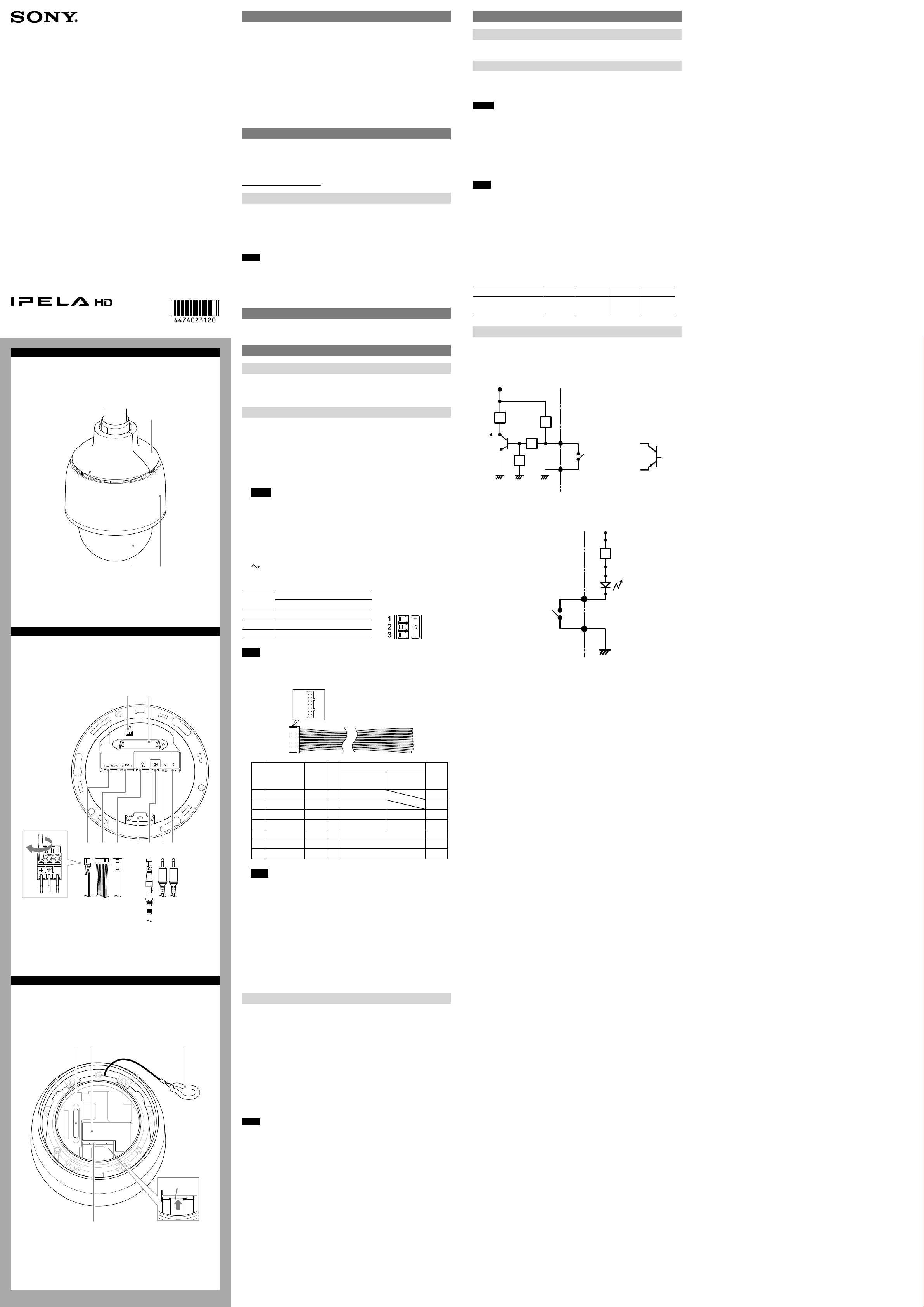
Connecting the I/O Cable
A
Location and Function of Part
Camera (Front)
Top sunshade
Wiring diagram for sensor input
Mechanical switch/open collector output device
Camera inside
3.3 V
Outside
Dome cover
Sunshade
Top Unit (Bottom)
Reset switch
This switch returns the setting of the device to the factory default setting.
1. Move the INIT switch in the direction indicated by and connect with
camera.
2. Turn on power and wait 1 minute. After the initialization is completed, the
camera starts.
3. Check that the camera has started and turn off the power to remove camera.
4. Move the INIT switch back to its original position.
Notes
Resetting the device removes all customized settings. It is recommended ˎ
that users save the settings as necessary. Instructions on how to save
settings are available in the User’s Guide.
The reset switch should always be returned to its original position. ˎ
Otherwise your device is reset to its factory default setting whenever it is
turned on.
Wiring diagram for alarm output
Camera connection terminal
Connect to the camera connection terminal of the camera.
B
AC 24 V (power input) terminal
Use the supplied AC connector to connect to the 24 V AC power supply system.
Pin No.
1 AC24V+
2 Frame Ground
3 AC 24V-
Note
Be sure to connect the Frame Ground to the specified terminal.
Pin name
AC24V
10 kohms
2.2 kohms
10 kohms
10 kohms
GNDGND
Magnet relay
24 V AC
24 V DC,
1 A or less
Sensor Input 1, 2, 3, 4
GND
Camera inside
Alarm Output +
Alarm Output –
GND
Mechanical
switch
Outside
24 V DC
R
Circuit example
GND
or
Open collector
output device
I/O (Input/Output) port
Provides four sensor inputs and two alarm outputs.
(continued on the reverse side)
Note
For details about functions and settings, see the user’s guide.
LAN (network) port (RJ-45)
Connect to a 10BASE-T or 100BASE-TX network using a network cable (UTP,
category 5).
Harness holder
Attach the supplied band mount.
(video output) terminal
Outputs a composite video signal. Use the supplied monitor cable to connect to
the camera.
(microphone input) terminal (minijack, monaural)
Connect a commercially available microphone.
C
(line output) terminal (minijack, monaural)
Connect to a commercially available speaker with a built-in amplifier.
Camera (Top)
Camera connection terminal
Connect to the camera connection terminal of the top unit.
Rating Label
This label shows the name of device and its electric rating.
Built-in wire rope
The wire rope is used for fall-prevention.
SD memory card slot
This slot is used for an optional SD memory card.
Images captured by the camera can be stored into an inserted memory card.
Be sure that the printed side of a memory card and the product specifications
label face in the same direction, and then insert the card firmly into the slot. (a)
This unit only supports memory card formats compatible with the SD/SDHC
standards.
Note
For information about Sony-approved SD memory cards, contact your Sony
dealer.
Printed side
D
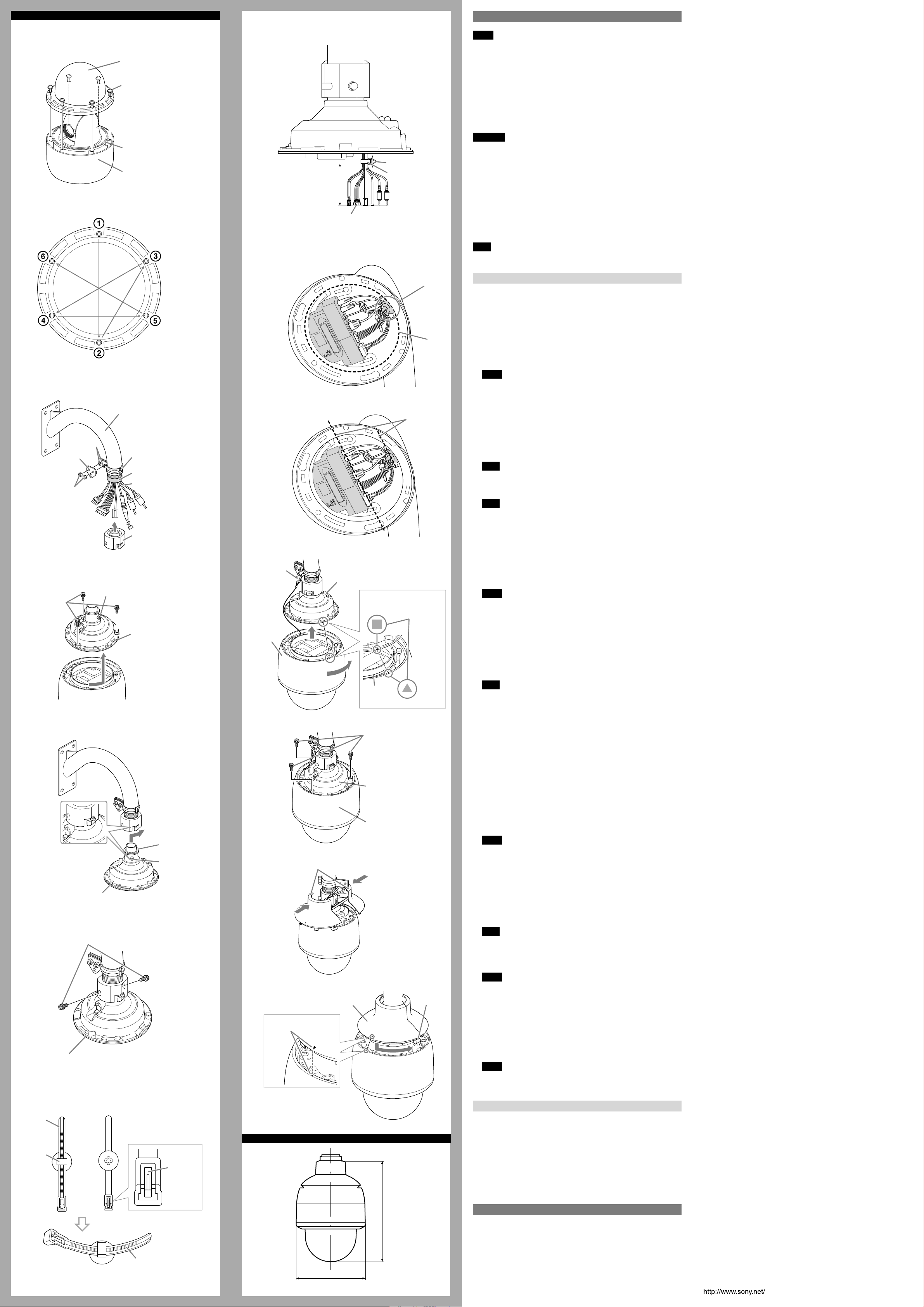
How to install the camera
1
a
b
2,3
Bolts
Wire
bracket
Nuts
4
Dome cover
Screws (6)
O-ring
Camera
Mounting arm
(not supplied)
Wire-fixing belt
Shield tape
(not supplied)
Cable
Coupling
b
8
9,10
Fallprevention
wire
100 mm to 125 mm
(4 inches to 5 inches)
Cable
Top unit
Band mount
Harness band
c
Keep parallel
Installation
Notes
Do not allow water to come in contact with the power cable, connection ˎ
cables or connectors, as it may cause water leakage into this device, and
subsequent damage.
The mounting arm (not supplied) to which the device is attached should have ˎ
xing screws of NPT 1 1/2” specied by a Sony dealer. Using an unspecied
mounting arm may cause water leakage into this device, and subsequent
damage. Be sure to use the specied mounting arm.
The lens zoom and angle may result in a blurred or inclined image within the ˎ
range above the horizon of the lens position.
To prevent the dome cover from damage and stain, do not remove the ˎ
protecting sheet from the dome cover until the setting is completed.
WARNING
If installing the camera in high location, such as high wall, entrust the ˎ
installation to a professional contractor or service personnel.
The camera should be securely installed on a location strong enough to ˎ
support the weight of the camera and the mounting arm. Otherwise, the
camera and mounting arm may fall and cause serious injury.
For the fall-prevention of the camera, make sure to use the wire rope. ˎ
If the bolts are attached loosely or loosen, the camera and parts may fall. There ˎ
may also be a risk of water leakage. Make sure to tighten the bolts and screws
so that they will not loosen.
Check the camera is attached securely, the screws, etc. are not loosened ˎ
periodically, at the least once a year. Depending on the usage conditions,
periodic inspections should be conducted more frequently.
Note
Use the supplied screws to install the unit. Using other screws may cause damage
inside the unit.
a
b
How to Install
Before installation
Referring to the installation manual of the mounting arm (not supplied), drill the
required holes for the mounting screws and the connection cable. Then install
the mount arm in advance. After that, wrap the screw part of the mounting arm
in a shield tape (not supplied).
How to install the camera
1 Attach the dome cover to the camera. (a)
Tighten the six screws in the specified order (1 to 6). (b)
Notes
Remove the drafting tape from the O-ring before attaching the dome ˎ
cover.
Be sure to properly place the O-ring in the groove rmly before attaching ˎ
the dome cover. If the O-ring is not properly and rmly placed, waterproof
performance may be compromised.
The six screws should be tightened to 1.2 N•m. ˎ
2 Attach the supplied wire-fixing belt and wire bracket to the mounting
arm (not supplied). Then secure the wire-fixing belt and wire bracket to
the mounting arm by tightening two nuts.
Note
The two bolts should be tightened to 5.2 N•m.
3 Screw the supplied coupling on the mounting arm.
Note
If the coupling is attached loosely or loosens, the camera may fall. Securely
put the coupling around the mounting arm so that it will not loosen.
4 Remove the three bolts from the top part of the camera, and turn the top
unit until it stops, then pull it upward to remove it from the camera.
Have a 5 mm (7/32 inch) hex wrench ready to loosen the bolts.
Camera
Camera system SNC-WR632: Camera FHD (1080 60P)
SNC-WR602: Camera HD (720 60P)
Signal system NTSC/PAL switching system
Image device 1/2.8 type CMOS
Effective picture elements
SNC-WR632: Approx. 2,140,000
SNC-WR602: Approx. 1,370,000
Synchronizing Internal synchronization
Minimum illumination SNC-WR632: 1.4 lx (F1.6/AGC ON/50 IRE (IP))
SNC-WR602: 1.0 lx (F1.6/AGC ON/50 IRE (IP))
Horizontal resolution 480 TV (analog video output)
Video S/N 50 dB or more (AGC 0 dB)
Lens
Focal length SNC-WR632: f = 30.2 mm to 904.9 mm (35 mm
SNC-WR602: f = 33.0 mm to 990.0 mm (35 mm
Maximum relative aperture F1.6 (wide), F4.7 (tele)
Minimum object distance 300 mm
Mechanism
Pan 360°, endless rotation
Maximum speed: 700°/s
Tilt 220° (with auto invert function)
Maximum speed: 700°/s
Interface
Network port 10BASE-T/100BASE-TX, auto negotiation (RJ-45)
I/O port Sensor input: × 4, make contact
Alarm output: × 2, 24 V AC/DC, 1 A
(mechanical relay outputs electrically isolated
from the camera)
Video output VIDEO OUT: BNC, 1.0 Vp-p,
75 ohms, unbalanced, sync negative
SD card slot
Microphone input Minijack (monaural)
Recommended load impedance 2.2 kohms
Line input Minijack (monaural)
Recommended load impedance 10 kohms
Line output Minijack (monaural), Maximum output level:
1 Vrms
Serial communication RS485/RS422
Others
Power supply HPoE+ 4 line power-supply
24 V AC ± 10%, 50 Hz/60 Hz
Power consumption Max. 80 W
Operation temperature 24 V AC: –40 °C to +50 °C (–40 °F to +122 °F)
HPoE+: –5 °C to +50 °C (23 °F to +122 °F)
Activation temperature 24 V AC: –40 °C to +50 °C (–40 °F to +122 °F)
HPoE+: 0 °C to +50 °C (32 °F to +122 °F)
Storage temperature –20 °C to +60 °C (–4 °F to +140 °F)
Operating humidity 20% to 80%
Storage humidity 20% to 95%
Dimensions (Diameter/Height)
ø222 mm × 324.1 mm (ø8 3/4 inches ×
12 7/8 inches) (Not including the projecting parts)
Mass Approx. 4.1 kg (9 lb 0.6 oz)
Supplied accessories Dome cover (1)
Top sunshade (1)
Coupling (1)
Wire-fixing belt (1)
Wire bracket (1)
Bolts (2)
Power supply connector 3-pin (1)
I/O harness 14-pin (1)
Monitor cable (1)
Harness band (1)
Band mount (1)
Installation manual (1 set)
CD-ROM (supplied programs) (1)
Optional accessories
Dome Cover Smoked YT-LDR632S
Design and specifications are subject to change without notice.
equivalent)
equivalent)
Plug-in-power supported (rated voltage: 2.5 V DC)
* A selector menu allows switching between
microphone input and line input
5 Attach the top unit to the mounting arm.
Place the locking screws fixed to the top unit in the groove of the
coupling and turn the top unit until it stops, in the direction of the arrow.
Bolts (3)
Locking screws (2)
Top unit
Align the triangular
and square marks
Camera
Notes
Remove the drafting tape from the waterproof seal before attaching the ˎ
mounting arm.
Be sure to verify that the locking screws are not loose. If the locking screws ˎ
are loose, the camera may fall. The locking screws should be tightened to
5.2 N•m.
Be sure to tighten the waterproof seal properly to the top unit before ˎ
attaching; otherwise, waterproof performance may be compromised.
6 Attach the two supplied bolts to the screw holes of the coupling and
tighten them.
O-ring
Note
The two bolts should be tightened to 5.2 N•m.
7 Run the supplied harness band through the band-mounting hole (a), tie
5
11
Bolts (3)
the cables at 100 mm to 125 mm (4 inches to 5 inches) from the cable
head (b).
If the tied position is not appropriate, push the release button of the
harness band to loosen, and tie the cables again.
8 Secure the band mount to the harness holder (a), and connect the cables.
Push the cables into the top unit (b).
Be sure that all cable connection sides of the top unit are in parallel with
the harness holder. (c)
Top unit
Camera
9 Hook the fall-prevention wire of the camera on the hole of the wire
bracket.
10
Align the triangular mark of the camera and square mark of the top unit
and push the camera into the top unit. Then turn the camera until it
stops, in the direction of the arrow.
6
7
a
Harness
band
Harness
mount
Top unit
Top unit
Bolts (2)
Waterproof
seal
Locking
screws (2)
Release
button
12
13,14
Align the triangular marks
E
Top sunshades
Top sunshade
Notes
Be sure to properly place the O-ring in the groove rmly before attaching ˎ
the camera. If the O-ring is not properly and rmly placed, waterproof
performance may be compromised.
Be sure that the camera connection terminal of the top unit is in parallel ˎ
with the harness holder before pushing the camera into the top unit.
To prevent the cables from getting caught, push the slack part of the ˎ
cables into the top unit before attaching the camera.
11
Attach the camera to the top unit using the three bolts which were
removed in step 4.
Note
The three bolts should be tightened to 5.2 N•m.
12
Separate the provided top sunshade and reattach the separated parts
above the camera to return the top sunshade to its original form.
Notes
Run the fall-prevention wire through the top sunshade. ˎ
Screw
Securely attach the top sunshade so that the snap hook will not get caught ˎ
in it.
13
Align the respective triangular marks of the camera and top sunshade
and push the top sunshade into the camera. Then turn the sunshade
until it stops, in the direction of the arrow.
14
Secure the camera and top sunshade using the screw on the top
sunshade.
Notes
Please make sure to attach the top sunshade. The top sunshade prevents ˎ
the device from overheating in direct sunlight.
The screw should be tightened to 1.2 N•m. ˎ
Removing the camera
1 Remove the one screw that secures the top sunshade to the camera in
Step 14 of “How to install the camera” to remove the top sunshade.
2 Remove the three bolts used in Step 11 of “How to install the camera.”
3 Turn the top unit to the position where the triangular mark of the
camera and the square mark of the top unit align, and pull the camera
out downwards.
4 Remove the fall-prevention wire of the camera from the hole of the wire
/8)
7
bracket.
Specifications
Always have the stopper side
face down and tie the cables.
ø222 (8 3/4)
324.1 (12
Unit: mm (inches)
Network
Protocol TCP/IP, ARP, ICMP, HTTP, FTP (server/client), SMTP
(client), DHCP (client), DNS (client), NTP (client),
SNMP (MIB-2), RTP/RTCP
Compression
Video compression format JPEG/H.264
Audio compression format G.711/G.726 (40, 32, 24, 16 kbps)
Maximum frame rate SNC-WR632: JPEG/H.264: 60 fps (1920 × 1080)
SNC-WR602: JPEG/H.264: 60 fps (1280 × 720)
 Loading...