

Page 1

3-619-675-11 (1)
Network Camera
Quick Reference
Guide de référence rapide
Kurzanleitung
SNC-VL10P
GB
FR
DE
© 2002 Sony Corporation
Page 2

Owner’s Record
The model and serial numbers are located at
the bottom. Record these numbers in the
spaces provided below.
Refer to these numbers whenever you call
upon your Sony dealer regarding thi s
product.
Model No. Serial No.
WARNING
To prevent fire or shock hazard, do
not expose the unit to rain or
moisture.
For AC Adaptor
To avoid electrical shock, do not
open the cabinet. Refer servicing to
qualified personnel only.
Important
Nameplate is locat e d on the bottom.
For customers in the U.S.A.
This equipment has been tested and found to
comply with the limits for a Class B digital
device, pursuant to Part 15 of the FCC
Rules. These limits are designed to pr ovide
reasonable protection against harmful
interference in a residential installation . This
equipment generates, uses, and can radiate
radio frequency energy and, if not install e d
and used in accordance with the instructions,
may cause harmful interference to radio
communications. However, th ere is no
guarantee that interference wll not occur in a
particular installation. If this equipment does
cause harmful interf erence to radio or
television reception, which can be
determined by tu rning the equipm ent off and
on, the user is encouraged t o t r y to correct
the interference by one or more of the
following measures:
– Reorient or relocate th e re cei vin g an tenn a .
– Increase the separation between the
equipment and receiver.
– Connect the equipment in to an ou tlet o n a
circuit different from that to which the
receiver is connected.
– Consult the dealer or an experienced radio/
TV technician for help.
GB
2
You are cautioned that any changes or
modifications not expressly approved in this
manual could vo id your authori ty to ope rate
this equipment.
The shielded interface cable recommended
in this manual must be used with this
equipment in order to compl y with the limits
for a digital device purs uan t to Sub part B o f
Part 15 of FCC Rules.
If you have any questions about this
product, you may call:
Sony’s Business Information Center
(BIC) at 1-800-686-7669
or Write to: Sony Customer Information
Services Center
6900-29, Daniels Pa rkway, PMB 330
Fort Myers, Florida 33912
Declaration of Conformity
Trade Name: SONY
Model No: SNC-VL10P
Responsible Party: Sony Electronics I nc.
Address: 68 0 Ki nd e r ka m ac k
Road, Oradell, NJ
07649 USA
Telephone No: 201-930-6972
This device complies with part 15 of the
FCC Rules.
Operation is subject to the follo win g two
conditions:
(1) this device may not cause harmful
interference, and
(2) this device must accept any
interference received, including
interference that may cause undesired
operation.
Voor de klanten in Nederland
• Dit apparaat bevat een vast ingebouwde
batterij die niet vervangen hoeft te worden
tijdens de levensduur van het apparaat.
• Raadpleeg uw leverancier indien de batterij
toch vervangen moet worden. De batterij
mag alleen vervangen worden door
vakbekwaam servicepersoneel.
• Gooi de batterij miet weg maar
lever deze in als klein chemisch
afval (KCA).
• Lever het apparaat aan het
einde van de levensduur in voor
recycling, de batterij zal dan op
correcte wijze verwerket
worden.
Page 3

Table of Contents
Overview
Features .............................................. 4
Supplied Accessories .........................5
Using the CD-ROM Manuals ............6
CD-ROM System Requirements...6
Preparations .................................. 6
Reading the Operating Instructions
in the CD-ROM .................6
Location and Functions of Parts and
Controls .............................................. 7
Installation and
Connections
Assigning t he IP Address to
the Camera .........................................9
Connecting the Camera to
a Computer ........................9
Connecting the Camera to
a Local Network ..............10
Assigning the IP Adress Using
the Setup Program ...........11
Installing the Camera .......................14
Mounting the Camera .................14
Adjusting the Focus, Iris and
Zoom ............................... 14
Adjusting the Flange Focal
Length .............................15
Applicable Lens ..........................17
Connecting to a Network .................17
Accessing the Camera Using
the Web Browser ..............................18
Appendix
Precautions ...................................... 19
Operating Precautions ................ 19
Typical CCD Phenomena ................ 20
Specifications .................................. 20
GB
GB
3
Page 4

B Overview
Features
Monitoring through network
The live image from the camera can be
monitored using the W e b browser on the
computer connecte d to a network.
Up to 100 users can view the image from one
camera at the same time.
Available Web browsers
Microsoft Internet Explorer
later
Netscape Navigator
Ver. 4.x-series
Usable with various types of
network
The camera c an b e co nn ected to various
types of network: E thernet, cable modem,
xDSL or analog modem.
Image transmission using an Email or FTP server
You can send still images from the camera
as an attachment of an E-mail o r to an FTP
server by synchronizing with an alarm. The
image can also be transmitted periodically
regardless of alarms.
Alarm function
The camera is equipped with two sets of
alarm output. The alarm output can be
triggered by the built-in activity detection
function, or the sensor input (1 input).
1)
Ver. 5.0 or
2)
Ver. 4.7 or later of
Wavelet compression charging a
lower load to network
The compression using the Wavelet
algorithm transmits images with a high
compression ratio (
the load to the network.
1
/10 to 1/200), thus reduces
CS mount and auto iris lens
connector provided
Although a vari-focal l ens is mounte d to the
camera as standard equipment, you can use
an optional CS-mount lens. Th e camera is
equipped with an auto iris lens connector
(DC servo type).
CCD IRIS™
3)
function allowing a
wide luminance adjustment
The camera is provided with a CCD IRIS
function that automatically adjusts the
luminance level for optimum output level.
When incoming light is excessive, this
function automatically adjusts the shutter
speed to cut expos ure equivalent to 10
aperture stop s or lower.
RS-485/RS-232C transparency
interface
Various per ipheral devi ces can be co nnected
to the camera via the RS-485 or RS-232C
transparency interface.
. . . . . . . . . . . . . . . . . . . . . . . . . . . . . . . . . . . . . . . . . . . . . . . . . . . . . . . . . . . . . . . . . . . . . . . . . . . . . . . . . . . . .
1) Microsoft, Window s, Internet Explorer and MS-DOS are registered trademarks of Microsof t
Corporation in the Uni t ed States and/or other countries.
2)Netscape Navigator is a registered trademark of Netscape Communications Corporation in the
U.S. and other countries.
3)CCD IRIS™ is a trademark of Sony Corp or at io n.
GB
4 Features
Page 5
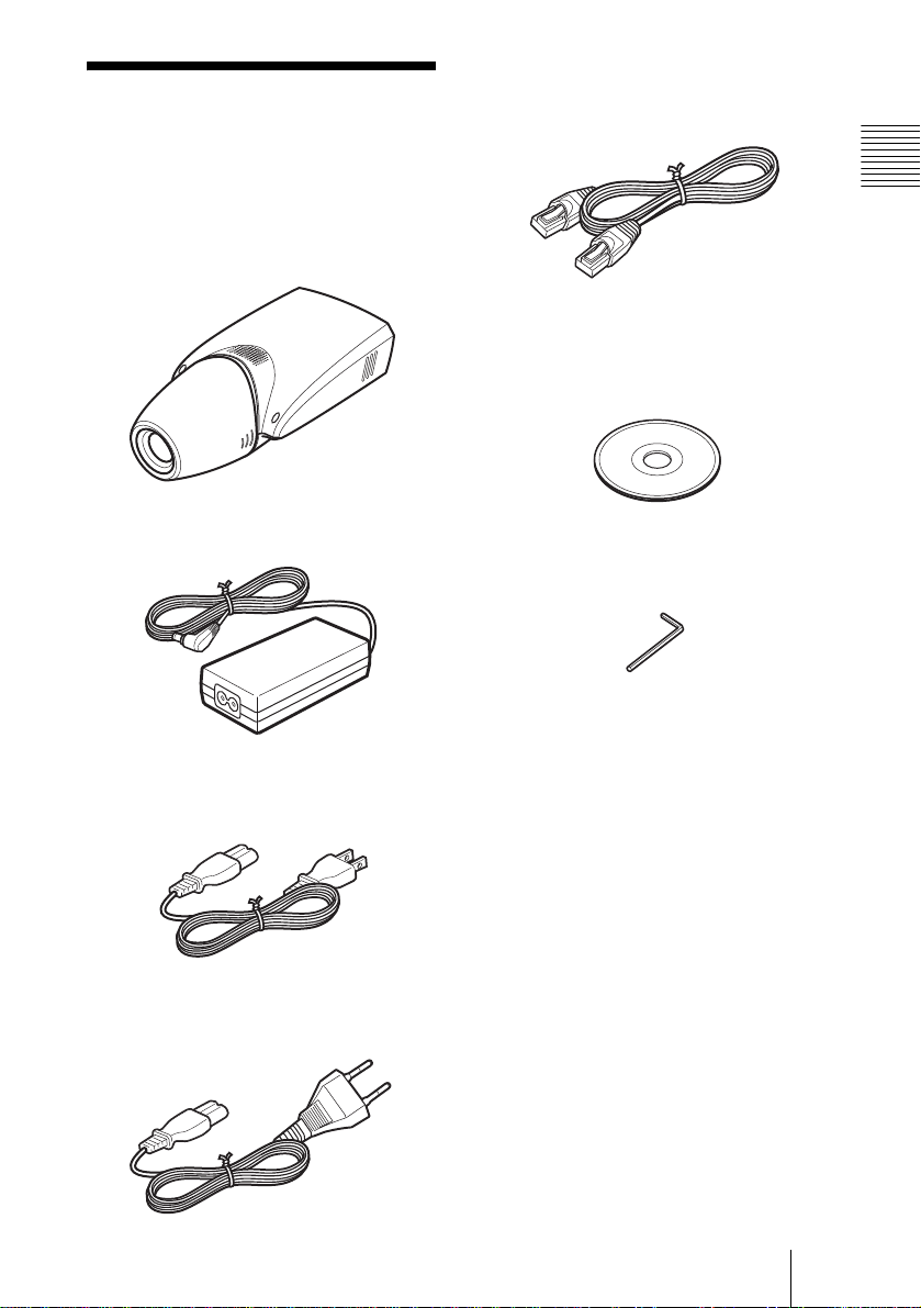
Supplied Accessories
Ethernet cable (1)
(UTP Category 5 cross cable)
When you unpack, check that all the
supplied accessories are included.
Camera (1)
AC power adaptor (1)
AC power cord (USA and Canadian
model only) (1)
Overview
CD-ROM (including the Setup
Program and Operating Instruction s)
(1)
Hexagonal wrench for flange focal
length adjustment (1)
AC power cord (European model
only) (1)
Supplied Accessories
GB
5
Page 6

Using the CD-ROM Manuals
The supplied CR-ROM disc includes
Operating Instructions for the SNC-VL10P
(English, French and Ger man versions).
Reading the Operating Instructions in the CD-ROM
To read the Operating Instructions contained
in the CD-ROM disc, do the following.
1 Insert the supplied CD-ROM disc into
your CD-ROM drive.
CD-ROM System Requirements
The following are requir ed to ac ce s s th e
supplied CD-ROM di sc.
• Computer: PC with MMX Pentium 166
MHz or faster CPU
• Installed memory: 64 MB or more
• CD-ROM drive: ×8 or faster
• Monitor: Monitor suppor ting resolutio n of
800 × 600 or higher
When the se requir ements ar e not met , access
to the CD-ROM disc may be slow, or not
possible at all.
Preparations
The Adobe Acrobat Reader Version 4.0 or
later must be installed on your computer in
order to use the Operating Instructions
contained in the CD-ROM disc.
Note
If Adobe Acrobat Reader is not installed, it
may be downloaded from the foll owi ng
URL:
http://www.adobe.com/products/acrobat/
readstep.html
2 Double-click the Manual folder.
3 Double-click the version you want to
read.
You can select from among English,
Français and Deutsch versions.
A PDF file of the Operating Instructions
opens.
Note
If you lose the CD-ROM di sc or become
unable to read its content, for example
because of a hardware failure, conta ct a
Sony service representative.
. . . . . . . . . . . . . . . . . . . . . . . . . . . . . . . . . . . . . . . . . . . . . . . . . . . . . . . . . . . . . . . . . . . . . . . . . . . . . . . . . . . . .
• MMX and Pentium are registere d trade marks of In tel Cor poration or its subsidi arie s in the Unite d
States and other countries.
• Adobe and Acrobat are registered trademarks of Adobe Systems Incorporated in the United States
and/or other countries.
GB
6 Using the CD-ROM Manuals
Page 7
Location and
2345 6 7 8
Functions of Parts
and Controls
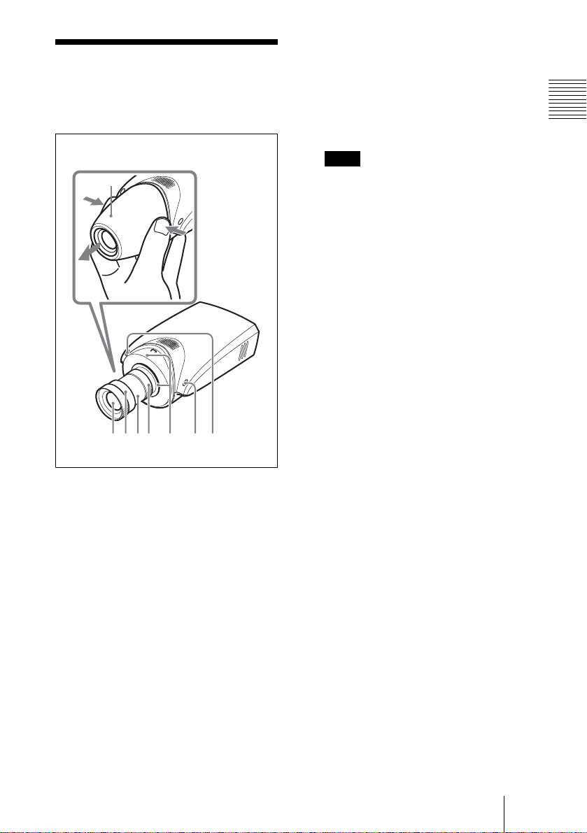
Front
1
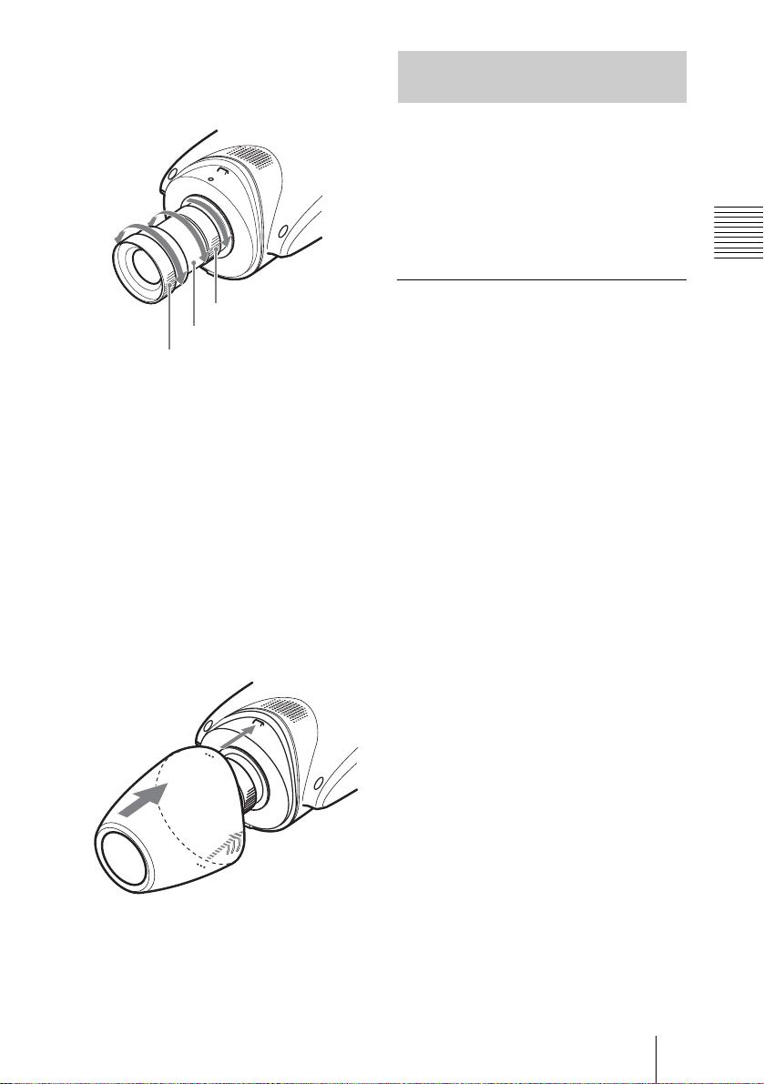
1 Lens cover
To remove, press both sides of the cover.
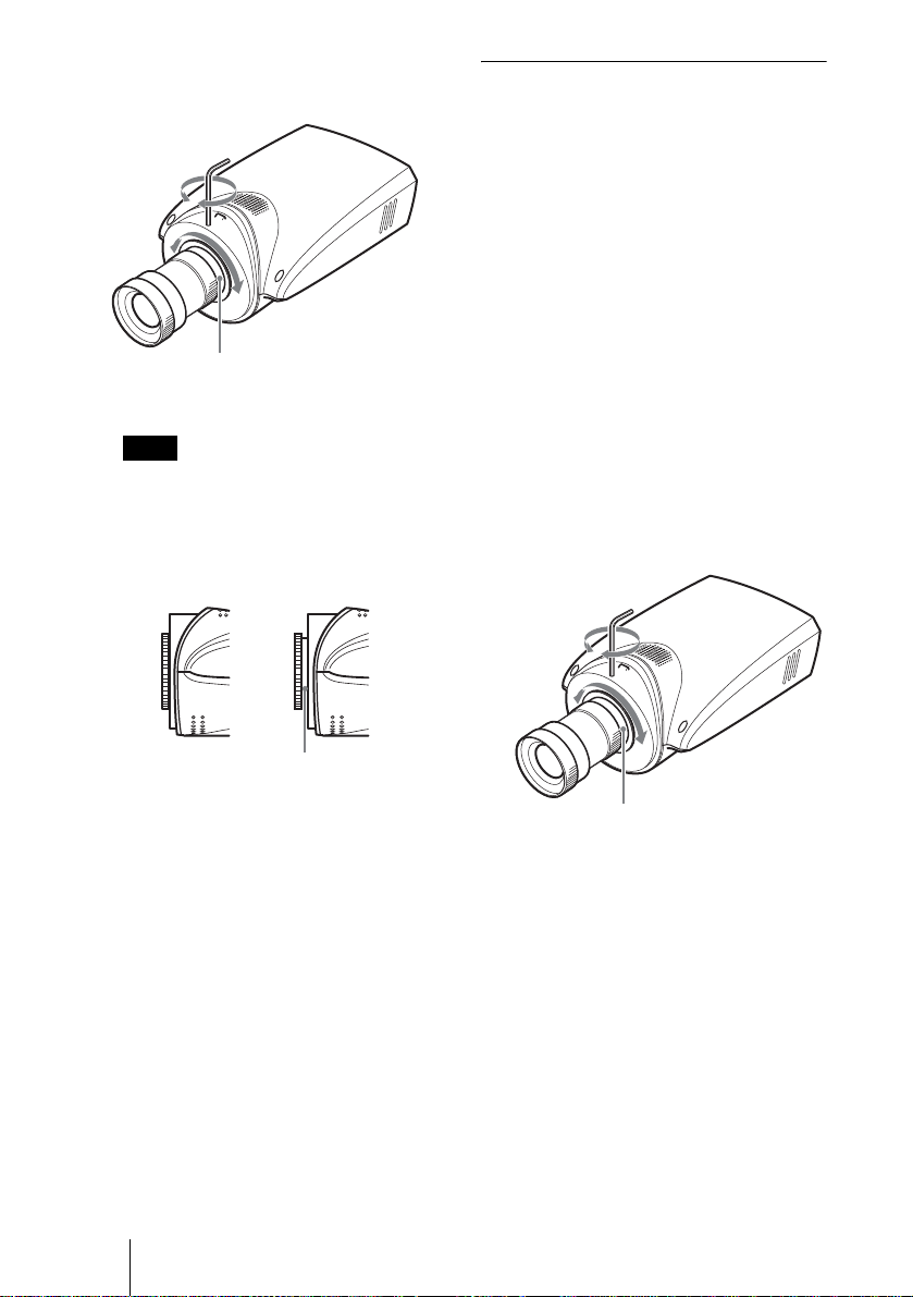
6 Flange focal length adjustment
ring and fixing screw
The flange focal length adjustment is
necessary when you have changed the
lens. Loosen the fixing screw, turn the
ring to adjust the flange focal length, and
tighten the screw.
Note
The flange focal length has been
adjusted at the fac tory for the supplie d
lens. Readjustment is necessary when
you change the lens only.
7 System start/image
compression indicator (orange)
This indicator lights when the power is
supplied to the camera and the system is
starting. It goes off when the system has
started.
Later, wh en a user acce s s es the came ra,
the image compression starts and the
indicator flashes.
8 Power/network indicator (green)
This indicator lights when the power is
supplied to the camera and goes off after
a while.
Later, when the camera is connected to a
network, this indicator flashes every two
seconds. If the camera is disconnected
from the network, it flashes every four
seconds.
Overview
2 Lens
A vari-focal lens is m ounte d as stan dard
equipment.
3 Focus ring
Turn this ring toward NEAR to focus on
a closer object; toward FAR to focus on
a farther object.
4 Zoom ring
Turn this ring toward TELE for
telephoto, or toward WIDE for wide angle.
5 Iris ring
Turn this ring to adjust the iris manually.
Location and Functions of Parts and Controls
GB
7
Page 8
9q
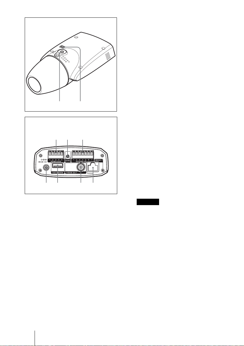
Bottom
qaq
q
qs LEVEL (video level) adjustment
volume
Adjust the signal level for a DC servotype auto iris lens (optional).
qd SENSOR I/O (Input/Output) port
This port is provided with one sens or
input and two sensor outputs.
The alarm settings using this port can be
performed using the menu for the
Administrat or on the We b browser.
For the pin assignment , see “Pin
assignment” on page 22.
;
Rear
s
d
qf qg qh qj
9 Installation/tripod hole
Use this hole when attaching the camera
to a wall, ceiling or tripod (screw: 1/4”,
20 UNC)
q; Auto iris lens connector
The power and control signal is supplied
to the lens when the lens iris cable
(optional, DC servo type) is connected.
qa RS485/232C port
Use this port when controlling a
peripheral device from a computer via
the camera, using the RS-485 or RS232C protocols .
The RS-485 and RS-232C protocols can
be selected using the menu for the
Administrator on the Web br owser.
For the pin assignment, see “Pin
assignment” on page 22.
qf DC IN 12 V (power input)
connector
Connect the supplied AC power adaptor.
qg USB MODEM port
Connect a USB modem (optional).
qh VIDEO OUT (video output)
connector (BNC type)
Outputs a composite vid eo signal.
Connect to a composite vi deo input
connector of a vi deo monitor, VCR, etc.
qj 10BASE-T (network) port
Connect to a network or computer using
an Ethernet cable.
Caution
When using a LAN cable: For safety, do
not connect to the connector for
peripheral device wiring that might have
excessive voltage.
GB
8 Location and Functions of Parts and Controls
Page 9
B Installation and Connect ions
Assigning the IP Address to the Camera
To connect th e ca m e r a t o a ne twork, you
need to assign a new IP address to the
camera.
You can assign the IP address in two ways:
• Using the supplied setup program
• Using the ARP (Address Resolution
Protocol) commands
This section explains how to assign the IP
address using the setup program stor ed in the
supplied CD-ROM. For this method,
connect the camera to a comp u t e r using the
supplied Ethernet cable, or to a local
network using a commerciall y available
Ethernet cable.
For the use of the ARP command, see th e
Operating Instructions st ored in the
supplied CD-ROM.
Note
For determining the IP address to be
assigned to the camera, consult your system
administrator.
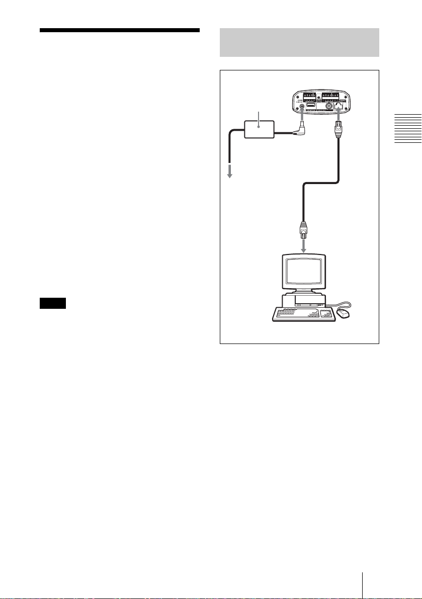
Connecting the Camera to a Computer
SNC-VL10P
AC power adaptor
(supplied)
Power cord
(supplied)
to an AC outlet
Network
connector
DC IN
12 V
Ethernet cable
(cross, supplied)
Computer
10BASE
-T
Installation and Connec tions
1 Using the supplied Ethernet
cable (cross), connect the
10BASE-T port of the camera to
the network connector of a
computer.
2 Connect the power cord to the
AC power adaptor (both
supplied), and connect the DC
IN 12 V connector of the camera
to an AC outlet.
Assigning the IP Address to the Camera
GB
9
Page 10
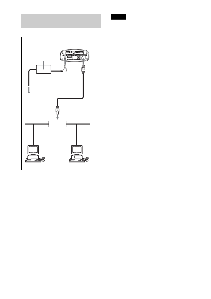
Connecting the Camera to a Local Network
SNC-VL10P
AC power adaptor
(supplied)
10
BASE-T
Power cord
(supplied)
to an
AC outlet
DC IN
12 V
Ethernet cable
(straight, not
supplied)
10BASE-T
Hub
Network
Notes
• To avoid the risk of damaging the data,
turn off the power of the equipment to be
connected before connectin g an Ethernet
cable.
• Plug the connectors of the Ethernet cable
fully to the end. A loose connection ma y
cause noise. To unplug the connector, pull
out by the connector itself.
1 Using a commercially available
Ethernet cable, connect the
10BASE-T port to a hub in the
network.
Use a UTP Category 5 straight cable for
the connect i on .
2 Connect the power cord to the
AC power adaptor (both
supplied), and connect the DC
IN 12 V connector of the camera
to an AC outlet.
GB
10 Assigning the IP Address to the Camera
Page 11
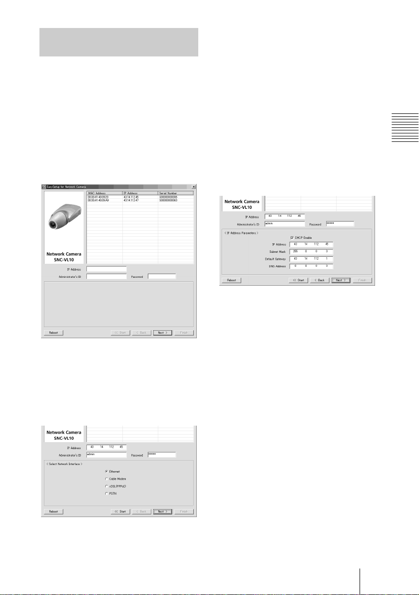
Assigning the IP Adre ss Using the Setup Program
1 Insert the supplied CD-ROM
disc into your CD-ROM drive.
2 Double-click the Setup folder.
5 Select the network interface you
use for connecting the camera.
Ethernet: LAN
Cable Modem: Cable modem
xDSL (PPPoE): ADSL, VDSL, SDSL
or other DSL
PSTN: Conventional analog telephone
line
3 Double-click EasySetup.exe.
The setup program starts. The program
detects the SNC-VL10P cameras
connected on the local netw ork an d lists
them.
4 Click on the MAC address or IP
address of the camera you want
to assign a new IP address.
The <Select Network Interface>
window appears.
6 Click Next.
The <IP Address Parameters> window
for the selected network interface
appears.
e.g., when Ethernet is selected
7 Set the items.
e.g., when Ethernet is selected
DHCP Enable check box: Click to
show the check mark when you want
to assign an IP address to the camera
automatically through the DHCP
server. To assign an IP address
manually, clear th e che ck box a nd f ill
the following boxes.
IP address: Type a new IP address for
the camera.
Subnet Mask: Type the subnet mask.
Default Gateway: Type the default
gateway.
DNS Address: Type the IP address of
DNS 1 (Domain Name Server 1).
Installation and Connec tions
Assigning the IP Address to the Camera
11
GB
Page 12
Note
The setting items for the Cable Modem,
xDSL or PSTN are the same as those on
the Network Setting page of the
Administrator menu, which is displayed
on the Web browser. See “Configuring
the Network – Network Setting Page” in
the Operating Instructions stored in the
supplied CD-ROM.
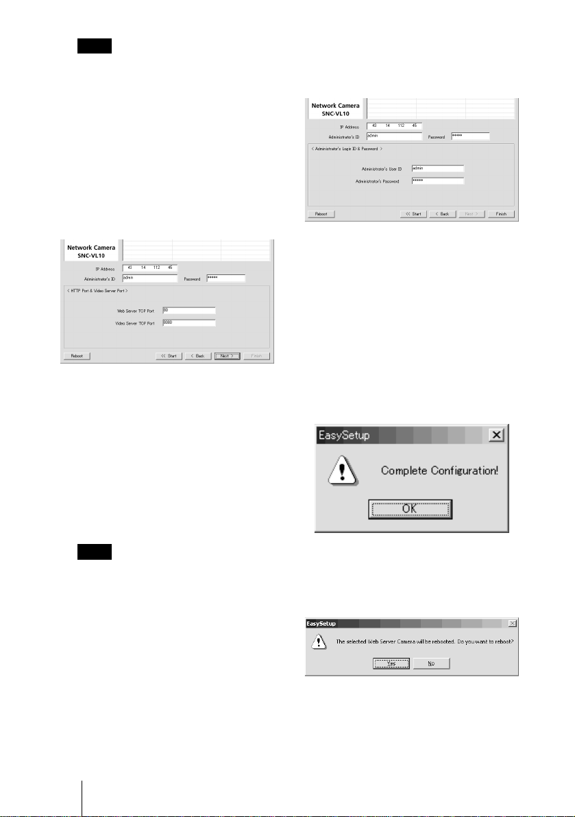
8 Click Next.
The <HTTP Port & Video Server Port>
window appears.
9 Set the items.
Web Server TCP Port: Type the TCP
port number (1 to 6 5535) used to
access the camera and for th e ca mera
to transmit the data. The default
setting is 80.
Video Server TCP Port: Type the TCP
port number (1 to 6553 5) used f or the
camera to transmit the shot images.
The default setting is 8080.
10
Click Next.
The <Administrator’s Login ID &
Password> window appears.
11
Type the Administrator’s User
ID and Administrator’s
Password up to 9 characters.
The default settings of the
Administrator’s User ID and
Administrator’s Password are “admin.”
We recommend that you change them.
12
Click Finish.
The Complete Configuration dialog
appears.
Note
You cannot set the same port number for
both ports.
GB
12 Assigning the IP Address to the Camera
13
Click OK.
The IP address of the camera in the list
changes, and the setup is completed.
Page 13

14
Click Yes to reboot the camera.
It will take 10 to 20 seconds to rebo ot the
camera.
To reboot the camera during the
setup
You can reboot the camera during the setup
by clicking Reboot at the bo tto m of the
window. It will take 10 to 20 seconds to
reboot the camera.
Installation and Connec tions
Assigning the IP Address to the Camera
13
GB
Page 14
Installing the Camera
Mounting the Camera
To attach the camera to a tripod , mounting
bracket, suspension bracket, etc., use the
appropriate screw (U1/4”, 20 UNC) that fits
the installation/tripod hole on the bottom of
the camera.
The following mounting screw can be used.
U1/4”, 20 UNC
= 4.5 mm ± 0.2 mm
(ISO standard)
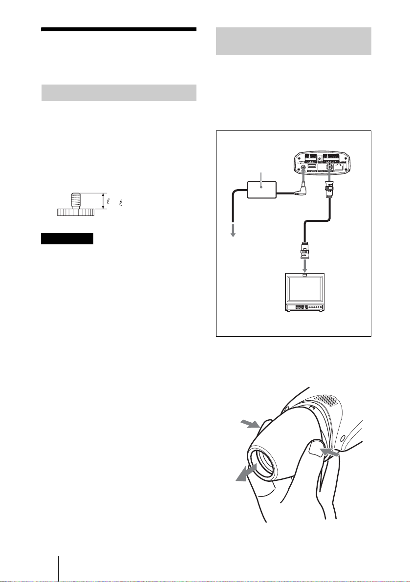
Adjusting the Focus, Iris and Zoom
After mounting the camera, aim the camera
at an object and adjust the fo cus, iris and
zoom.
For these adjustments, we recommend using
the output signal from the VIDEO OUT
connector of the camera.
SNC-VL10P
AC power adaptor
(supplied)
VIDEO
OUT
Power cord
(supplied)
DC IN
12 V
ATTENTION
If installing the camera on the ceiling, be
sure it is secure. If not securely installed, the
camera may fall and injury may occur.
If the camera is installed on the ceiling using
equipment such as a bracket, housing and
motored swivel base (pan/tilt), do the
following:
• Use a tripod screw and securely tighten it
with a screwdriver. Order the tripod screw
(Sony Part No. 3 -174-693-01) fr om your
nearest Sony dealer.
• Install the camera on a flat surface.
to an AC outlet
Video monitor, etc.
Composite
video input
1 Remove the lens cover from the
camera.
GB
14 Installing the Camera
Page 15
2 Turn the iris ring from C (close)
little by little until roughness is
eliminated from the image.
2 Iris ring
3 Zoom ring
4 Focus ring
3 Turn the zoom ring to determine
the view angle.
Adjusting the Flange Focal Length
The flange focal length is the distance from
the lens mounting plane to the image plane.
If you cannot obtai n a precise focus by
turning the focus ring after you have
changed the lens, adjust the flange focal
length as follows.
Once you have adjusted it, readjustment is
not necessary until you ch ange the lens.
When a CS-mount lens is attached
1 If the lens employs the manual
iris adjustment, set the iris fully
open. If the lens employs the
automatic iris adjustment,
illuminate the surroundings so
that the iris becomes fully open.
Installation and Connec tions
4 Turn the focus ring to adjust the
focus.
The view angle changes simultaneously.
5 Repeat steps 2 to 4 until the
desired shooting range and
focus are obtained.
6 After the adjustments, replace
the lens cover.
2 Point the camera to a subject
about 3 m (10 feet) away and
display the shot image on the
monitor screen.
A subject, on which you can observe the
focus condition distinctively, such as
letters, fine patterns, etc. is suitable.
3 Turn the zoom on the lens fully
to telephoto.
4 By observing the monitor
screen, turn the focus ring on
the lens to adjust the focus on
the subject.
5 Turn the zoom on the lens fully
to wide-angle.
6 Loosen the fixing screw using
the supplied hexagonal wrench,
and turn the flange focal length
adjustment ring to adjust the
focus on the same subject used
in step 4.
Do not turn the focus ring on the lens.
Installing the Camera
15
GB
Page 16
Hexagonal wrench
(supplied)
When the supplied vari-focal lens is
replaced
1 Point the camera to a subject
about 20 cm (8 inches) away.
A subject, on which you can observe the
focus condition distinctively, such as
letters, fine patterns, etc, is suitable.
2 Turn the zoom ring of the lens
fully to WIDE.
Flange focal length
adjustment ring
Note
Do not loosen the flange focal length
adjustment ring excessively. T he ri ng
may be damaged if you loosen it until
the silver base of the ring appears.
This way
Not this way
Silver base
7 Repeat steps 3 to 6 until you
achieve sharp focus both in the
telephoto and wide-angle
positions.
8 Tighten the fixing screw using
the hexagonal wrench.
3 Turn the focus ring of the lens
fully to
∞ (infinite).
4 Loosen the fixing screw using
the supplied hexagonal wrench,
and turn the flange focal length
adjustment ring until the correct
focus is obtained.
Hexagonal wrench
(supplied)
Flange focal length adjustment ring
5 Tighten the fixing screw using
the hexagonal wrench.
GB
16 Installing the Camera
Page 17

Applicable Lens
When you want to replace the supplied lens
with a new one, CS-mount lenses with the
following lens mount surface can be
attached to the camera.
Lens mount surface
6 mm
or less
Notes
• Be sure to use a lens whose projected part
from the lens mount surface is less than 6
mm. Mounting a lens with a projected part
greater than 6 mm may damage the
internal mechanism of the camera.
• Be sure to use a lens whose mass is less
than 250 g (9 oz). If you ch oose to use a
heavier lens, secure it separately from the
camera.
Connecting to a Network
When the camera installation and
adjustments are completed, connect it to a
network.
You can connect the camera to a network, in
two ways:
• Using the 10BASE-T port
•Using the USB port
For the connection to a local net w ork, see
“Connecting the Camera to a Local
Network” on page 10.
For the connections using a cable modem,
xDSL modem or USB modem, see the
Operating Instructions stored in the
supplied CD-ROM .
Installation and Connec tions
Connecting to a Network
17
GB
Page 18
Accessing the Camera Using the Web Browser
When the networ k connection has been
completed, check that you can actually
access the camera using the Web browser
installed in your computer.
This section explains how to access the
camera using the Internet Explorer.
For details on the operatio ns us ing the W eb
browser, i.e. for using a Web browser that is
not the Internet Explorer, see the Operating
Instructions stored in the supplied CDROM.
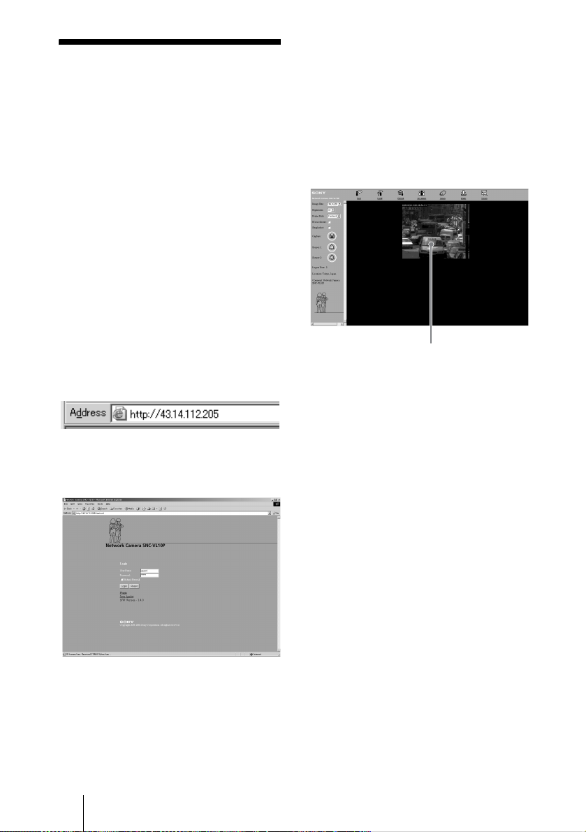
1 Start the Web browser on the
computer and type the IP
address of the camera in the
URL box.
2 Click Login.
The User Name “guest” and its
Password “guest” are set as default
settings. You can login the camera only
by clicking Login.
The Main Viewer page is displayed and
the monitor image from the camera
appears on the screen.
Monitor image
Now the installation and co nn e ction s of
the camera are completed.
The Login page of Network Camera
SNC-VL10P is displayed.
GB
18 Accessing the Camera Using the Web Browser
Page 19

B Appendix
Precautions
This Sony product has been designed with
safety in mind. However, if not used
properly electrical produ cts can cause fires
which may lead to serious body injury.
To avoid such accidents, be sure to heed the
following.
Heed the safety precautions
Be sure to follow the general safety
precautions, and the “Operating
Precautions.”
In case of a breakdown
In case of a system breakdown, discontinue
use and contact your authorized Sony dealer.
In case of abnormal operation
• If the unit emits smoke or an unusual
smell,
• If water or other foreign objects enter the
cabinet, or
• If you drop the unit or damage the cabinet:
1 Disconnect the camera cable and the
connecting cables.
2 C o ntact your authorize d So ny dea le r or
the store where you purchased the
product.
Operating Precau tions
Operating or storage location
Avoid operating or storing the camera in the
following locations:
• Extremely hot or cold places (Operating
temperature: –10°C to +50°C [14°F to
122°F])
• Exposed to direct sun light for a long tim e,
or close to heating equipment (e.g., near
heaters)
• Close to sources of strong magnetism
• Close to sources of powerful
electromagnetic radiation, such as radios
or TV transmitters
Transportation
When transporting the camera, repack it as
originally packed at the factory or in
materials of equal quality.
Cleaning
• Use a blower to remove dust from the lens
or optical filter.
• Use a soft, dry cloth to clean the external
surfaces of the camera. Stubborn stains
can be removed using a soft cloth
dampened with a small quantity of
detergent solution, then wipe dry.
• Do not use volatile solvents such as
alcohol, benzene or thinners as t hey may
damage the surface finishes.
About the fan
To prevent internal heat buildup, the camera
has a built-in fan. If the frame rate of the
camera becomes 1 fps although the other
frame rate value has been set using the
Frame Rate menu on the Web screen, the
built-in fan may be damaged. In this case,
contact your authorized So ny dealer.
Appendix
Precautions
19
GB
Page 20
Typical CCD Phenomena
The following ph e no me na may appear on
the monitor screen while you are using a
CCD color video camera. These phenomena
stem from the high sensitivity of the CCD
image sensors, and do not indicate a fault
within the camera.
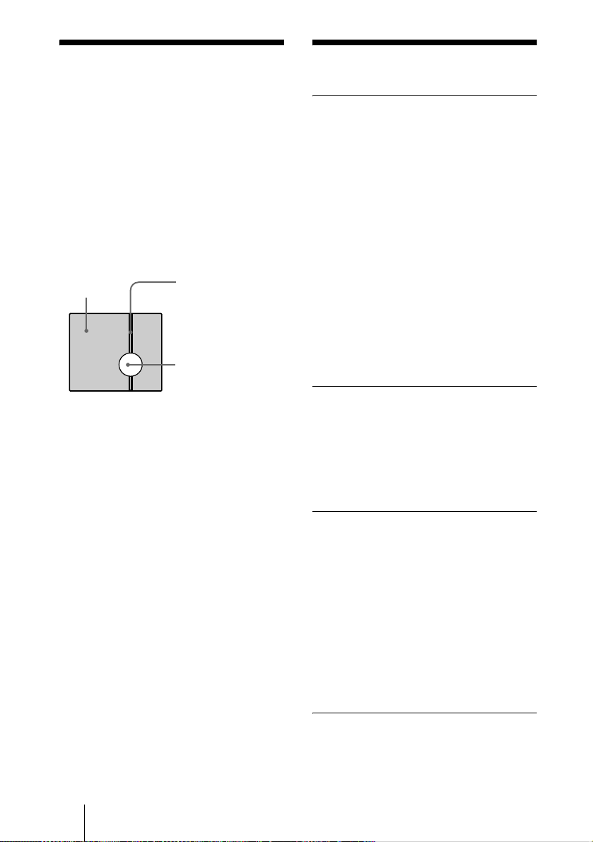
Vertical smear
A “smear” may appear to extend verti cally
from very bright subjects, as shown below.
Video monitor
screen
This phenomenon is common to CCD
imaging elements using an interline transfer
system, and is caused when electri c charge
induced by infrared radiation deep within
the photo sensor is transferred to the
resistors.
Aliasing
When shooting fine stripes, straight lines or
similar patterns, the lines may become
slightly jagged.
Blemishes
A CCD image sensor consists of an array of
individual picture elements (pixels). A
malfunctioning sensor element will show up
as a single pixel blemish in the image. This
is generally not a problem.
White speckles
When you shoot a poorly illuminate d object
at a high temperature, small white do ts m ay
appear all over the entire screen image.
Pale vertical smear
Very bright su b j ect
(such as an electric
lamp, fluorescent
lamp, sunlight, or
strong reflected light)
Specifications
General
CPU 32-bit RISC embedded processor
RAM 16 MB
Flash PROM 8 MB
OS Embedded realtime Linux
Protocol TCP/IP, PPP, PPPoE, ARP,
Compression Wavelet
Compression rate
Frame rate Max. 25 fps (360 × 288)
Image size 720 × 576, 720 × 288, 360 × 288,
Web browser Internet Explorer Ver. 5.0 or late r
Multi access Max. 100 users
Image rotation 0°, 90°, 180°, 270°
Others Activity detection, focus area
Image system
Image device1/3 type CCD, interline transfer
Effective pictu re elements
* “Super HAD CCD” is a registered trademark of
Sony Corporation.
Functions/performance
Horizontal resolution
Signal-to-noise ratio
Minimum illumination
Gain control AGC (Automatic Gain Control)
White balance ATW (Automatic Tracing White
CCD IRIS ON/OFF switchable
Flickerless mode
Lens (standard equipment)
Lens Vari-focal lens
Focal length 3.5 to 5.0 mm
View angle 73.9 to 33.8° (hori z o ntal), 56.3 to
RARP, ICMP, FTP, SMTP,
DHCP, HTTP, SNMP
10:1 to 200:1 (10 steps)
180 × 144, 90 × 72
Netscape Navigator Ver. 4.7 or
later of Ver. 4.x-series
setting
®*
(Super HAD CCD
752 (horizontal) × 582 (ve rti c al )
480 TV lines
50 dB
2 lux (AGC ON, F1.4, 50 %)
always ON
balance)
ON/OFF switchable
25.8° (vertical)
)
GB
20 Typical CCD Phenomena
Page 21
Iris Manual adjustment
F number F1.4
Lens mount CS-mount
Inputs/Outputs
Network port 10BASE-T Ethernet port (R J-45)
Interface RS-232C/RS-485
Auto iris lens connector
Video output connector
Sensor I/O port
USB Modem port
DC servo
VIDEO OUTPUT: BNC, 75 ohms,
unbalanced
Input: Sensor input
Output 1: Activity detection/
manual swit chable
Output 2: Relay through sensor
input/manual s witchable
Others
Power supply 12 V DC, from external AC power
Current consumption
Power consumption
Operating temperature
supply via the supplied AC
power adaptor
48 V DC via Ethernet power hub
(IEEE802.3af)
0.57 A (12 V DC)
0.20 A (48 V DC)
6.8 W (12 V DC)
9.6 W (48 V DC)
–10 °C to +50 °C (14 °F to 122 °F)
Storage temperature
–40 °C to +60 °C (–40 °F to 140
Operating humidity
Storage and transport humidity
Dimensions 96 × 63 × 186 mm (3
Mass Approx. 350 g (12 oz)
Supplied accessories
°F)
20 % to 80 % (free of
condensation)
20 % to 95 % (free of
condensation)
3
7
/8 inches) (w/h/d)
not including the projecting parts
AC power adaptor (1)
AC power cord (1)
Ethernet cable (UTP Category 5
cross cable) (1)
CD-ROM (setup program and
operating instructions) (1)
Hexagonal wrench for flange focal
length adjustment (1)
7
/8 × 2 1/2 ×
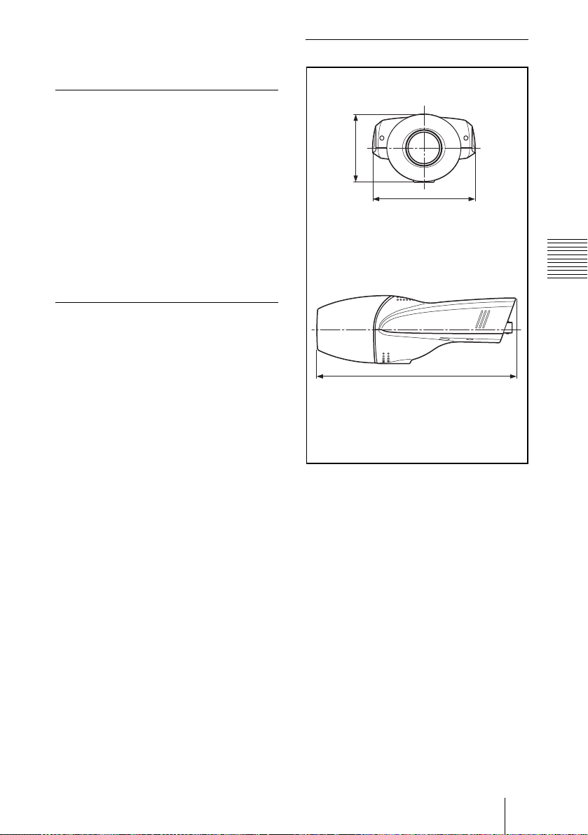
Dimensions
Front
/2)
1
63 (2
Side
7
96 (3
186 (7 3/8)
Unit: mm (inches)
/8)
Appendix
Specifications
21
GB
Page 22

Pin assignment
RS485/232C port
1 RS232C –RXD
2 RS232C
3 GND
4 RS485
5 RS485
–TXD
– A
– B
Sensor I /O port
1 Sensor In +
2 Sensor In
3 Sensor Out 1 +
4 Sensor Out 1
5 Sensor Out 2 +
6 Sensor Out 2
7 GND
–
–
–
Design and specifications are subject to
change without notice.
GB
22 Specifications
Page 23

Page 24

AVERTISSEMENT
Pour éviter tout risque d’incendie ou
d’électrocution, n’exposez pas cet
appareil à la pluie ou à l’humidité.
Adaptateur secteur
Afin d’écarter tout risque
d’électrocution, garder le coffret
fermé. Ne confier l’entretien de
l’appareil qu’à un personnel qualifié.
Important
La plaquette signaléti que se trouve audessous du produit.
FR
2
Page 25

Table des matières
Description générale
Caractéristiques .................................. 4
Accessoires fournis ............................5
Utilisation des manuels sur le
CD-ROM ............................................6
Configuration système requ ise pour
le CD-ROM .......................6
Préparation ....................................6
Lecture des instructions d’utilisation
sur le CD-ROM .................6
Emplacement et fonction des pièces et
commandes .........................................7
Installation et
raccordements
Attribution d’une adresse IP à la
caméra ................................................ 9
Raccordement de la caméra à un
ordinateur .......................... 9
Raccordement de la caméra à un
réseau local ......................10
Attribution de l’adresse IP à l’aide
du programme
d’installation ...................11
Installation de la caméra ..................14
Montage de la caméra .................14
Réglage de la mise au point, du
diaphragme et du zoom ...14
Réglage du tirage mécanique .....15
Objectifs compatibles .................17
Raccordement au réseau ...................17
Accès à la caméra avec le navigateur
Internet .............................................18
Appendice
Précautions ...................................... 19
Précautions d’utilisation ............ 19
Phénomènes caractéristiques du
CCD ............................................... 20
Spécifications .................................. 21
FR
FR
3
Page 26

B Description générale
Caractéristiques
Visualisation de l’image via un
réseau
Vous pouvez visualiser l’image de la caméra
en direct en utilisant le navigateur Internet
d’un ordinateur connecté à un réseau.
Jusqu’à 100 utilisateurs peuvent visualiser
simultanément l’image d’une même caméra.
Navigateurs Internet disponibles
Microsoft Internet Explorer
plus récente
Netscape Navigator
récente de la série 4.x
Utilisable avec divers types de
réseaux
Vous pouvez connecter la caméra à divers
types de réseaux : Ether net, modem câble,
xDSL ou modem analogique.
Transmission des images par email ou serveur FTP
La caméra peut envoyer des images fixes
comme pièces jointes à un e-mail ou vers un
serveur FTP lorsque des alarmes se
déclenchent. Elle peut égal ement envoyer
des images périodiquement
indépendamment des alarmes.
Fonction d’alarme
La caméra comporte deux sorties d’alarme.
La sortie d’alarme peut être déclenchée par
la fonction de détection d’activité de la
caméra ou par l’entr ée d’un capteur (1
entrée).
1)
version 5.0 ou
2)
version 4.7 ou plus
Compression Wavelet diminuant la
charge sur le réseau
L’algorithme de compression Wavelet
(compression par ondelettes) pe rmet de
transmettre les images avec un taux de
compression élevé (
la charge sur le réseau.
1
/10 à 1/200), ce qui réduit
Monture CS et connecteur
d’objectif à diaphragme
automatique
Bien que la caméra soit équipée en standard
d’un objectif va rifocale, vous pouvez
également utiliser un objectif à monture CS
en option. Elle comporte un connecteur
d’objectif à diaphragme automatiq ue
(asservi CC).
Fonction CCD IRIS™
3)
permettant
des réglages de luminance sur une
vaste plage
La fonction CCD IRIS règle
automatiquement la lum in a nce p our assure r
un niveau de sortie optimal. Lorsque
l’éclairage est excessif, cette fonction règle
automatiquement la vitesse d’obturation
pour réduire l’exposition à l’équivalent de
10 diaphragmes ou moins.
Interface transparente RS-485/
RS-232C
Divers périphériques peuvent être connectés
à la caméra via l’interface transparente RS485 ou RS-232C.
. . . . . . . . . . . . . . . . . . . . . . . . . . . . . . . . . . . . . . . . . . . . . . . . . . . . . . . . . . . . . . . . . . . . . . . . . . . . . . . . . . . . .
1) Microsoft, Windows , Int ernet Explorer et MS-DOS sont des m a rques déposées de Microsoft
Corporation aux États-Unis et/ou dans d’aut re s pays.
2)Netscape Navigator est une marque déposée de Netscape Communications Corporation aux ÉtatsUnis et dans d’autres pays.
3)CCD IRIS™ est une marque de Son y Corporation.
FR
4 Caractéristiques
Page 27

Accessoires fournis
Au déballage, assurez-vous qu’auc un des
accessoires fournis ne manque.
Caméra (1)
Adaptateur secteur (1)
Câble Ethernet (1)
(Câble UTP catégorie 5 croisé)
Description général e
CD-ROM (contenant le programme
d’installation et les instructions
d’utilisation) (1)
Clé hexagonale pour le réglage du
tirage mécanique (1)
Cordon d’alimentation (modèle pour
les États-Unis et le Canada
seulement) (1)
Cordon d’alimentation (modèle
européen seulement) (1)
Accessoires fournis
FR
5
Page 28

Utilisation des
manuels sur le CDROM
Le CD-ROM fourni contient les in structions
d’utilisation de la SNC-VL10P (versions
anglaise, française et allemande).
Configuration système requise pour le CD-ROM
La configuration suivante est requise pour
l’accès au CD-ROM fourni :
• Ordinateur : Ordinateur avec
microproces seur Pentium MM X 166 MHz
ou plus puissant
• Mémoire installée : 64 Mo ou plus
• Lecteur de CD-ROM : ×8 ou plus rapide
• Écran : Écran avec une résolution de 800 ×
600 ou plus
Si ces conditions ne sont pas satisfaites,
l’accès au CD-ROM peut être lent ou
impossible.
Lecture des instructions d’utilisation sur le CD-ROM
Pour lire les instructions d’utilisation se
trouvant sur le CD-ROM, procédez comme
suit :
1 Insérez le CD-ROM fourni dans le
lecteur CD-ROM.
2 Double-cliquez sur le dossier Manual.
3 Double-cliquez sur la version que
vous désirez lire.
Vous avez le choix en tre English,
Français et Deutsch.
Le fichier PDF contenant les
instructions d’utilisation s’ouvre.
Remarque
Si vous égarez le CD-ROM ou ne pa rvenez
pas à en lire le contenu (en raison d’une
défaillance du matériel), adressez-vous au
service après-vente Sony.
Préparation
Pour pouvoir ouvrir les instructions
d’utilisation se trouvant sur le CD-ROM, le
logiciel Adobe Acrobat Reader version 4.0
ou plus récente doit être installé sur
l’ordinateur.
Remarque
Si Adobe Acrobat Reader n’est pas installé
sur l’ordinateur , vo us po uv ez l e tél éc h arger
à l’adresse suivante :
http://www.adobe.com/products/acrobat/
readstep.html
. . . . . . . . . . . . . . . . . . . . . . . . . . . . . . . . . . . . . . . . . . . . . . . . . . . . . . . . . . . . . . . . . . . . . . . . . . . . . . . . . . . . .
• MMX et Pentium sont des marques déposées d’Intel Corporation ou de ses filiales aux États-Unis
et dans d’autr es pays.
• Adobe et Acrobat sont des marques déposées d’Adobe Systems Incorporated aux États-Unis et/ou
dans d’autres pays.
FR
6 Utilisation des manuels sur le CD-ROM
Page 29

Emplacement et
2345 6 7 8
fonction des pièces
et commandes
Face avant
1
5 Bague de diaphragme
Tournez cette bague pour régler le
diaphragme manuellement.
6 Bague de réglage du tirage
mécanique et vis de fixation
Un réglage du tirage mécanique est
nécessaire lorsque vous changez
d’objectif. Desserrez la vis de fixation,
réglez le tirage mécanique en tournant la
bague, puis resserrez la vis.
Remarque
Le tirage mécanique a été réglé en usine
pour l’objectif fourni. Il n’est nécessaire
de le régler à nouveau qu’après un
changement d’objec tif.
7 Témoin de démarrage du
système/compression d’image
(orange)
Ce témoin s’allume lorsque la caméra
est mise sous tension et que le système
démarre. Il s’éteint après le démarrage
du système.
Il clignote ensuite lorsqu’un utilisate ur
accède à la caméra et que la compression
d’image démarre.
Description général e
1 Bouchon d’objectif
Pour le retirer, appuyez des deux côtés
du bouchon.
2 Objectif
La caméra est dotée en standard d’un
objectif varifocale.
3 Bague de mise au point
Tournez cette bague vers NEAR pour
effectuer la mise au point sur un sujet
rapproché et vers FAR pour effectuer la
mise au point sur un sujet éloigné.
4 Bague de zoom
Tournez cette bague vers TELE pour
une prise de vues au téléob jectif et vers
WIDE pour une prise de vues au grandangle.
8 Témoin d’alimentation/réseau
(vert)
Ce témoin s’allume à la mise sous
tension de la caméra, puis s’éteint après
quelques instants.
Il clignote ensuite toutes les deux
secondes lorsque la caméra est
connectée à un réseau. Lorsque la
caméra est déconnectée du réseau, il
clignote toutes les quatre secondes.
Emplacement et fonction des pièces et commandes
FR
7
Page 30

9q
Face inférieure
qaq
q
;
Face arrière
s
d
qf qg qh qj
9 Orifice d’installation/trépied
Utilisez cet orifice pour fixer la caméra
sur un mur, un plafond ou un trépied
(filetage : 1/4 po., 20 UNC)
q; Connecteur d’objectif à
diaphragme automatique
Permet de brancher le câble de
diaphragme d’objectif (asservi CC en
option) pour l’alimentation et la
commande de l’objectif.
Vous pouvez sélectionner les protocoles
RS-485 et RS-232C sur le menu pour
l’administrateur dans le navigateur
Internet.
Pour le brochage, voir “Brochage” à la
page 23.
qs Bouton de réglage LEVEL
(niveau vidéo)
Permet de régl er le nivea u du signal pour
un objectif à diaphragme automatique
asservi CC (en option).
qd Port SENSOR I/O (entrée/sortie
de capteur)
Ce port comport e un e en tr é e et de ux
sorties de capteur.
Vous pouvez par a m étr e r les alarmes
utilisant ce port en utilisant le menu pour
l’administrateur dans le navigateur
Internet.
Pour le brochage, voir “Brochage” à la
page 23.
qf Connecteur DC IN 12 V (entrée
d’alimentation)
Permet de brancher l’adaptateur secteur
fourni.
qg Port USB MODEM
Permet de raccorder un modem USB (en
option).
qh Connecteur VIDEO OUT (sortie
vidéo) (type BNC)
Sortie du signal vidéo composite.
Raccordez ce port au connecteur
d’entrée vidéo composite d’un moniteur
vidéo, magnétoscope, etc.
qj Port 10BASE-T (réseau)
Raccordez ce port à un réseau ou un
ordinateur à l’aide d’un câble Ethernet.
qa Port RS485/232C
Permet de commander un périphérique
via la caméra depu is un ordinateur en
utilisant le protocole RS-485 ou RS232C.
FR
8 Emplacement et fonction des pièces et commandes
Attention
Lors de l’utilisation d’un c âble de réseau
local : par mesure de sécurité, ne la
raccordez pas à un connecteur po ur
périphérique ayant une te nsion
excessive.
Page 31

B Installation et raccordements
Attribution d’une adresse IP à la caméra
Pour connecter la caméra à un réseau vous
devez lui attribuer une nouvelle adresse IP.
Vous pouvez attribuer l’adresse IP de deux
manières :
• en utilisant le programme d’installation
fourni ;
• en utilisant les commandes ARP (Address
Resolution Protocol)
Cette section explique comment attribuer
l’adresse IP en utilisant le programme
d’installation sur le CD-ROM fourni. Pour
utiliser cette méthode, raccordez la caméra à
un ordinateur à l’aide du câble Ethernet
fourni ou à un réseau local à l’aide d’un
câble Ethernet en vente dans le commerce.
Pour l’utilisation des commandes ARP, voir
les instructions d’utilisation sur le CD-ROM
fourni.
Remarque
Pour déterminer l’adresse IP à attribuer à la
caméra, consultez votre administrateur
système.
Raccordement d e la caméra à un ordinate ur
SNC-VL10P
Adaptateur
secteur (fourni)
Cordon
d’alimentation
(fourni)
vers une prise
secteur
Connecteur
réseau
DC IN
12 V
Câble Ethernet
(croisé, fourni)
Ordinateur
10BASE
-T
1 Raccordez le port 10BASE-T de
la caméra au connecteur réseau
de l’ordinateur à l’aide du câble
Ethernet (croisé) fourni.
Installation et raccord em ents
2 Branchez le cordon
d’alimentation à l’adaptateur
secteur (tous deux fournis) et
raccordez le connecteur DC IN
12 V de la caméra à une prise
secteur.
Attribution d’une adresse IP à la caméra
FR
9
Page 32

Raccordement de la caméra à un réseau local
SNC-VL10P
Adaptateur
secteur (fourni)
10
BASE-T
Cordon
d’alimentation
(fourni)
vers une
prise secteur
10BASE-T
DC IN
12 V
Câble Ethernet
(droit, non fourni)
Concentrateur
Réseau
Remarques
• Pour ne pas risquer d’endommager les
données, mettez le matériel à connect er
hors tension avant de raccorder un câble
Ethernet.
• Enfoncez les connecteurs du câble
Ethernet complètem e nt. Une connexion
lâche peut pr ovoq uer de s bru its p ar asit es.
Pour débrancher le câble, tirez-le p ar le
connecteur lui-même.
1 Raccordez le port 10BASE-T à
un concentrateur du réseau à
l’aide d’un câble Ethernet en
vente dans le commerce.
Utilisez un câble UTP catégorie 5 droit
pour le raccordement.
2 Branchez le cordon
d’alimentation à l’adaptateur
secteur (tous deux fournis) et
raccordez le connecteur DC IN
12 V de la caméra à une prise
secteur.
FR
10 Attribution d’une adresse IP à la caméra
Page 33

Attribution de l’adresse IP à l’aide du programme d’installation
1 Insérez le CD-ROM fourni dans
le lecteur CD-ROM.
2 Double-cliquez sur le dossier
Setup.
3 Double-cliquez sur
EasySetup.exe.
Le programme d’installation démarr e.
Le programme détecte les caméras
SNC-VL10P connectées sur le réseau
local et en donne la liste.
5 Sélectionnez l’interface réseau
utilisée pour la connexion de la
caméra.
Ethernet : LAN (réseau local)
Cable Modem : Modem câble
xDSL (PPPoE) : ADSL, VDSL, SDSL
ou autre DSL
PSTN : Ligne téléphonique analogique
classique
6 Cliquez sur Next.
La fenêtre <IP Address Parameters>
s’affiche pour l’interface réseau
sélectionnée.
Si, par exemple, Ethernet est sélectionné
Installation et raccord em ents
4 Cliquez sur l’adresse MAC ou
l’adresse IP de la caméra à
laquelle vous désirez attribuer
une nouvelle adresse IP.
La fenêtre <Select Network Interface>
apparaît.
7 Définissez les paramètres.
Si, par exemple, Ethernet est sélectionné
Case à cocher DHCP Enable : Cochez
cette case en cliquant dessus si vous
désirez qu’une adresse IP soit
automatiquement att ribu é e à la
caméra par le serveur DHCP. Pour
attribuer l’adresse IP manuellement,
décochez la case et remplissez les
champs suivants.
IP address : Tapez une nouvelle adresse
IP pour la caméra.
Subnet Mask : Saisissez le m asque de
sous-réseau.
Default Gateway : Saisissez l’adresse
par défaut.
DNS Address : Saisissez l’adresse IP du
serveur DNS 1 (nom de domaine du
serveur 1).
Attribution d’une adresse IP à la caméra
11
FR
Page 34

Remarque
Les paramètres pour Cable Modem,
xDSL ou PSTN sont les mêmes que
celles de la page Network Setting du
menu de l’administrateur qui s’affiche
dans le navigateur Internet. Voir
“Configuration du réseau – Page
Network Setting” dans les instructions
d’utilisation sur le CD-ROM fourni.
8 Cliquez sur Next.
La fenêtre <HTTP Port & Video Se rver
Port> apparaît.
9 Définissez les paramètres.
Web Server TCP Port : Saisissez le
numéro du port TC P (1 à 65535)
utilisé pour accéder à la caméra et
pour l’émission des données par celleci. La valeur par défaut est 80.
Video Server TCP Port : Saisissez le
numéro du port TC P (1 à 65535)
utilisé pour l’émission des images
prises par la caméra. La valeur par
défaut est 8080.
10
Cliquez sur Next.
La fenêtre <Administrator’s Login ID &
Password> apparaît.
11
Tapez l’identifiant de
l’administrateur et le mot de
passe d’administrateur de 9
caractères au maximum.
L’identifiant d’administrateur “admin”
et le mot de passe “admin” sont spécifiés
par défaut. Nous vous recommandons
de les changer.
12
Cliquez sur Finish.
La boîte de dialogue Complete
Configuration s’affiche.
Remarque
Vous ne pouvez pas spécifier le même
numéro pour les deux ports.
FR
12 Attribution d’une adresse IP à la caméra
13
Cliquez sur OK.
L’adresse IP de la caméra sur la liste
change et la configuration est terminée.
Page 35

14
Cliquez sur Yes pour redémarrer
la caméra.
La caméra demande 10 à 20 secondes
pour redémarrer.
Pour redémarrer la caméra pendant
l’installation
Vous pouvez redémarrer la caméra pendant
l'installation en cliquant sur Reboot au bas
de la fenêtre. La caméra demande 10 à 20
secondes pour redémarrer.
Installation et raccord em ents
Attribution d’une adresse IP à la caméra
13
FR
Page 36

Installation de la caméra
Montage de la caméra
Pour fixer la caméra à un trépied, support de
montage, support de suspension, etc.,
utilisez une vis (U1/4 po., 20 UNC) adaptée
à l’orifice d’installation/trépied sous la
caméra.
La vis de montage suivante pe ut être utilisée.
U1/4 po., 20 UNC
= 4,5 ± 0,2 mm
(norme ISO)
ATTENTION
Assurez-vous que la caméra est bien fixée si
vous l’installez au plafond. Une caméra mal
fixée peut tomber et blesser quelqu’un.
Si vous montez la caméra au plafond avec
dispositif tel que support, boîtier ou socle
pivotant motorisé (rotation en panoramique/
inclinaison), procédez comme suit :
• Utilisez une vis de trépied et serrez-la à
fond avec un tournevis. Commandez la
vis de trépied (n° de pièce Sony : 3-174693-01) chez le revendeur Sony le pl us
proche.
• Installez la caméra sur une surface plate.
Réglage de la mi se au point, du diaphragme et du zoom
Après avoir monté la caméra, pointez-la vers
un sujet e t réglez la mise au p o int, le
diaphragme et le zoom.
Pour ces régla ges, nous vous recomma ndons
d’utiliser le signal de sortie du connecteur
VIDEO OUT de la caméra.
SNC-VL10P
Adaptateur
secteur (fourni)
VIDEO
OUT
Entrée
vidéo
composite
Cordon
d’alimentation
(fourni)
vers une prise
secteur
DC IN
12 V
Moniteur vidéo, etc.
1 Retirez le bouchon d’objectif de
la caméra.
FR
14 Installation de la caméra
Page 37

2 Tournez progressivement la
bague de diaphragme depuis la
position C (fermé) jusqu’à ce
que la rugosité de l’image
disparaisse.
2 Bague de diaphragm
3 Bague de zoom
4 Bague de mise au point
3 Tournez la bague de zoom pour
déterminer l’angle de vue.
4 Tournez la bague de mise au
point pour régler la mise au
point.
L’angle de vue change simultanément.
5 Répétez les opérations des
étapes 2 à 4 jusqu’à ce que vous
obteniez le champ de prise de
vues et la mise au point désirés.
6 Après les réglages, remettez le
bouchon d’objectif en place.
Réglage du tirage mécanique
Le tirage mécanique est la dist ance entre le
plan de monture de l’objectif et le plan de
l’image. Si, après un changement d’objectif,
vous ne parvenez pas à obtenir une mise au
point précise à l’aide de la bague de mise au
point, réglez le tirage mécanique comme il
est indiqué ci-dessous.
Une fois ce réglage effectué, il n’est pas
nécessaire de le modifier tant que vous ne
changez pas d’objectif .
Lorsque vous utilisez un objectif à
monture CS
1 Si l’objectif utilise un réglage
manuel du diaphragme, ouvrez
complètement le diaphragme.
Si l’objectif utilise un réglage
automatique du diaphragme,
éclairez le voisinage de façon
que le diaphragme s’ouvre
complètement.
2 Pointez la caméra sur un sujet
distant de 3 m (10 pi.) environ et
affichez l’image prise sur l’écran
du moniteur.
Choisissez un sujet sur lequel vous
pourrez observer distinctement la
condition de mise au point (sujet
comportant des lettres, des motifs fins,
etc.).
3 Tournez complètement le zoom
de l’objectif sur la position
téléobjectif.
Installation et raccord em ents
4 Tout en observant l’écran du
moniteur, tournez la bague de
mise au point de l’objectif pour
régler la mise au point sur le
sujet.
5 Tournez complètement le zoom
de l’objectif sur la position
grand-angle.
Installation de la caméra
15
FR
Page 38

6 Desserrez la vis de fixation à
l’aide de la clé hexagonale
fournie et tournez la bague de
réglage du tirage mécanique
pour régler la mise au point sur
le même sujet que celui utilisé à
l’étape 4.
Ne tournez pas la bague de mise au point
de l’objectif.
Lors du remplacement de l’objectif
varifocale fourni
1 Pointez la caméra sur un sujet
distant de 20 cm (8 po.) environ.
Choisissez un sujet sur lequel vous
pourrez observer distinctement l a
condition de mise au point (sujet
comportant des lettres, des motifs fins,
etc.).
Clé hexagonale
(fournie)
Bague de réglage du tirage
mécanique
Remarque
Ne desserrez pas trop la bague de
réglage du tirage mécanique. Vous
risquez de l’endommager si vous la
desserrez jusqu’à ce que la base argentée
soit visible.
Correct
Incorrect
2 Tournez complètement la bague
de zoom de l’objectif sur WIDE.
3 Tournez complètement la bague
de mise au point de l’objectif sur
∞ (infini).
4 Desserrez la vis de fixation à
l’aide de la clé hexagonale
fournie et tournez la bague de
réglage du tirage mécanique
jusqu’à ce que la mise au point
soit correcte.
Clé hexagonale
(fournie)
Bague de réglage du tirage méc anique
Base argentée
7 Répétez les opérations des
étapes 3 à 6 jusqu’à ce que la
mise au point soit nette sur les
positions téléobjectif et grandangle.
8 Resserrez la vis de fixation à
l’aide de la clé hexagonale.
FR
16 Installation de la caméra
5 Resserrez la vis de fixation à
l’aide de la clé hexagonale.
Page 39

Objectifs compatibles
Vous pouvez remplacer l’objectif fourni par
un objectif à monture CS ayant une surface
de monture telle qu’illustrée ci-dessous.
Surface de mo n tu r e de
l’objectif
6 mm
maximum
Remarques
• La longueur de partie saillant e de
l’objectif par rapport à la surface de
monture de l’objectif ne doit pas être
supérieure à 6 mm. Le mécanisme interne
de la caméra risquerait autrement d’être
endommagé.
• Utilisez un obje ctif pesan t moins de 250 g
(9 onces). Si vous devez utiliser un
objectif plus lourd, fixez-le séparément de
la caméra.
Raccordement au réseau
Après avoir terminé l’installation et les
réglages de la caméra, raccordez-l a au
réseau.
Vous pouvez raccorder la caméra au réseau
de deux manières :
• par le port 10BASE-T
•par le port USB
Pour le raccordement à un réseau local, voir
“Raccordement de la caméra à un réseau
local” à la page10.
Pour les raccordement s à l’aide d’un
modem câble, modem xDSL ou modem USB,
voir les instructions d’utilisation sur le CDROM fourni.
Installation et raccord em ents
Raccordement au réseau
17
FR
Page 40

Accès à la caméra avec le navigateur Internet
2 Cliquez sur Login.
Le nom d’utilisateur “guest ” et le mot de
passe “guest” sont spécifiés comme
paramètres par défaut. Pour accéder à la
caméra, il vous suffit de cliquer sur
Login.
Après avoir terminé le raccordement au
réseau, assure z-vous que vous po uv ez
accéder à la caméra avec le navigateur
Internet installé sur votre ordinateur.
Cette section explique comment accéder à la
caméra avec Internet Explorer.
Pour plus d’informations sur la marche à
suivre avec un navigateur Internet autre
qu’Internet Explorer, voir les instructions
d’utilisation sur le CD-ROM fourni.
1 Démarrez le navigateur Internet
sur l’ordinateur et tapez
l’adresse IP de la caméra dans la
zone URL.
La page d’ouverture de session de la
Network Camera SNC-VL10P
s’affiche.
La page du visualiseur principal
s’affiche et l’image de contrôle de la
caméra appar aît à l’écran .
Image de contrôle
L’installation et les raccordements de la
caméra sont maintenant terminés.
FR
18 Accès à la caméra avec le navigateur Internet
Page 41

B Appendice
Précautions
Ce produit Sony a été conçu avec l’accent
sur la sécurité. Notez, toutefois, que tout
appareil électrique mal utilisé peut
provoquer un incendie dans lequel on risque
d’être gravement blessé.
Pour éviter de tels accidents, observez les
précautions suivantes :
Respectez les précautions de
sécurité
Observez impérativement les précauti ons de
sécurité générales ainsi que celles qui sont
indiquées sous “Précautions d’utilisation”.
En cas de panne
En cas de panne, cessez l’utilisation et
adressez- vous à votre reve ndeu r Sony agré é.
En cas de fonctionnement anormal
• Si la caméra dégage de la fumée ou une
odeur anormale
• Si de l’eau ou des objets étrangers ont
pénétré dans le boîtier
• Si la caméra est tombée ou si son boîtier
est endommagé
1 Débranchez le câble de la camér a et les
câbles de raccordement.
2 Adressez-vous à un revendeur Sony agréé
ou au magasin où vous avez acheté le
produit.
Précautions d’utilisation
Lieu d’utilisation ou de rangement
Évitez d’utiliser ou de ranger la caméra dans
les endroits suivants :
• endroits très chauds ou froids (température
de fonctionnemen t : –10 à +50°C [14 à
122°F])
• endroits longuement expo sés aux rayons
directs du soleil ou à proximité d’un
appareil de chauffage (radiateurs, pa r
exemple)
• proximité de sources magnétiques
puissantes
• proximité d’un rayonn ement
électromagnétique puissant (émetteurs de
radio ou de télé vision, par exempl e)
Transport
Transportez la caméra dans son emballage
d’origine ou dans un emballage d’égale
qualité.
Nettoyage
• Utilisez un pinceau soufflant pour enlever
la poussière de l’objectif ou du filtre
optique.
• Utilisez un chiffon dou x et sec pour
nettoyer l’extérieur de la caméra. Vous
pouvez éliminer les taches persistantes e n
frottant avec un chiffon doux imbibé d’une
petite quantité de solutio n détergente, p uis
en essuyant.
• N’utilisez pas de solvants volatils tels
qu’alcool, benzène ou diluants. Ils
pourraient endo mmager la finition.
Ventilateur
La caméra est dotée d’un ventila teur intégré
qui empêche une accumulation de chaleur à
l’intérieur. Si le ta ux d e tra me d e la c a méra
n’est plus que de 1 image/seconde alors que
vous avez spécifié une autre valeur dans le
menu Frame Rate s ur l’écran Web, il se pe ut
que le ventilateur soit endom ma g é.
Adressez-vous alors à votre revendeur Sony
agréé.
Appendice
Précautions
19
FR
Page 42

Phénomènes caractéristiques du CCD
Il se peut que vous cons ta ti ez les
phénomènes ci-dessous sur l’écran du
moniteur pendant l’utili sati on d ’une c améra
vidéo couleur CCD. Ces phénomènes sont
dus à la haute sensibilité des capteurs
d’image CCD et ne sont pas le si gne d’une
anomalie de la caméra.
Maculage vertical
Des sujets très lumineux peuvent provoquer
un maculage vertical comme sur la figure cidessous.
Écran du
moniteur
vidéo
Maculage vertical
pâle
Sujet très lumineux
(lampe électrique,
lampe fluorescente,
rayons du soleil ou
forte lumière
réfléchie, par
exemple)
Crénelage
Lorsque vous filmez de fines rayures, des
lignes droites ou des motifs similaires, les
lignes peuvent apparaître légèrement “en
escalier”.
Défauts d’aspect
Un capteur d’image CCD est constitué de
nombreux éléments d’image individuels
(pixels). Le dysfonctionnement d’un
élément du capteur se manifeste par le
palissement d’un pixel dans l’image. Ceci
ne pose généralement pas de problème.
Mouchetures blanches
Lorsque vous filmez un sujet faiblement
éclairé sous une température élevée, de
petits points blancs peuvent apparaît re sur
toute la surface de l’image à l’écran.
Ce phénomène est commun aux photosites
des CCD à transfert d’interligne et se
manifeste lorsque la charge électrique
induite par le rayonnement infrarouge à
l’intérieur du capteur photosensible est
transférée aux résistances.
FR
20 Phénomènes caractéristiques du CCD
Page 43

Spécifications
Généralités
Processeur Processeur RISC 32 bits embarqué
Mémoire morte (RAM)
Mémoire flash PROM
Système d’exploitation
Protocole TCP/IP, PPP, PPPoE, ARP,
Compression Wavelet (par ondelettes)
Taux de compression
Taux de trame
Taille d’i mage
Navigateur Internet
Accès multiple
Rotation d’image
Divers Détection d’activité, définition de
Système d’image
Disposit if d ’image
Pixels utiles
* “Super HAD CCD” est une marque déposée de
Sony Corporation.
16 Mo
8 Mo
Linux temps réel embarqué
RARP, ICMP, FTP, SMTP,
DHCP, HTTP, SNMP
10 : 1 à 200 : 1 (10 niveaux)
25 images/seconde (360 × 288) au
maximum
720 × 576, 720 × 288, 360 × 288,
180 × 144, 90 × 72
Internet Explorer version 5.0 ou
plus récente
Netscape Navigator version 4.7 ou
plus récente de la série 4.x
100 utilisateurs au maximu m
0°, 90°, 180°, 270°
la zone de mise au point
1
/3, transfert d’interlig n e
CCD
(Super HAD CCD
752 (horizontalement) ×
582 (verticalement)
®*
)
Fonctions/performances
Résolution horizontale
480 lignes TV
Rapport signal/bruit
50 dB
Éclairage minimum
2 lux (AGC activé, F1,4, 50 %)
Réglage du gain
AGC (Réglage automatique du
gain) toujours activé
Balance des blancs
ATW (Balance des blancs à suivi
automatique)
CCD IRIS Activable/désactivable
Mode Flic k erless (anti-scintill ement)
Activable/désactivable
Objectif (équipement standard)
Objectif Objectif varifocale
Longueur de focale
3,5 à 5,0 mm
Angle de vue 73,9 à 33,8° (ho rizontalement),
56,3 à 25,8° (verticalement)
Diaphragme Régl age manuel
Nombre F F1,4
Monture d’objectif
Monture CS
Entrées/sorties
Port réseau Port 10BASE-T Etherne t (R J-45)
Port USB Modem
Interface RS-232C/RS-485
Connecteur d’objectif à diaphragme au tom atique
Asservi CC
Connecteur de sortie vidéo
VIDEO OUTPUT : BNC,
75 ohms, asymétrique
Port d’E/S de capteur
Entrée : Entrée de capteur
Sortie 1 : Détection d’activité/
commutable manuellement
Sortie 2 : Entrée de relais à travers
un capteur/commutable
manuellement
Appendice
Spécifications
21
FR
Page 44

Divers
Alimentation 12 V CC depuis le secteur via
Consommation de coura nt
Consommation électrique
Température de fonctionnement
l’adaptateur secteur fourni
48 V CC via un concentrateur
autoaliment é Eth ernet
(IEEE802.3af)
0,57 A (12 V CC)
0,20 A (48 V CC)
6,8 W (12 V CC)
9,6 W (48 V CC)
–10 à +50 °C (14 à 122 °F)
Température de stockage
–40 à +60 °C (–40 à 140 °F)
Humidité de fonctionnement
Humidité de stockage et de transport
Dimensions 96 × 63 × 186 mm (3
Poids 350 g (12 onces) environ
Accessoires fou r ni s
20 à 80 % (sans condensation)
20 à 95 % (sans condensation)
3
/8 po.) (l/h/p)
7
7
/8 × 2 1/2 ×
pièces saillantes non compri ses
Adaptateur secteur (1)
Cordon d’alimenta tion (1)
Câble Ethernet (câble UTP
catégorie 5 croisé) (1)
CD-ROM (programme
d’installation et inst r u ctions
d’utilisat io n) (1)
Clé hexagonale pour le réglage du
tirage mécanique (1)
Dimensions
Face avant
/2)
1
63 (2
Face latérale
7
/8)
96 (3
186 (7 3/8)
Unité : mm (pouces)
FR
22 Spécifications
Page 45

Brochage
Port RS485/232C
1 RS232C –RXD
2 RS232C
3 GND
4 RS485
5 RS485
–TXD
– A
– B
Port d’E/S du capteur
Appendice
1 Entrée capteur +
2 Entrée capteur
3 Sortie capteur 1 +
4 Sortie capteu r 1
5 Sortie capteur 2 +
6 Sortie capteu r 2
7 GND
–
–
–
La conception et les spécifications sont
susceptibles d’être modifiées sans préavis.
Spécifications
23
FR
Page 46

WARNUNG
Um Feuergefahr und die Gefahr eines
elektrischen Schlages zu ve r mei den,
darf das Gerät weder Regen noch
Feuchtigkeit ausgesetzt werden.
Für Netzgerät
Um einen elektrischen Schlag zu
vermeiden, darf das Gehäuse nicht
geöffnet werden. Überlassen Sie
Wartungsarbeiten stets nur
qualifiziertem Fachpersonal.
Wichtig
Das Typensch ild be fi n de t sich an der
Unterseite.
Für Kunden in Deutschland
Dieses Produkt kann im kommerziellen und
in begrenztem Maße auch im industrie llen
Bereich eingesetzt werden. Dies ist ein e
Einrichtung, we lche die Funk-Entstörung
nach Klasse B besitzt.
DE
2
Page 47

Inhaltsverzeichnis
Übersicht
Merkmale ...........................................4
Mitgeliefertes Zubehör .......................5
Verwendung der CD-ROM-
Anleitungen ........................................ 6
CD-ROM-
Systemvoraussetzungen .... 6
Vorbereitungen ............................. 6
So lesen Sie die
Bedienungsanleitung auf
der CD-ROM ....................6
Lage und Funktionen der Teile und
Bedienelemente .................................. 7
Installation und Anschlüsse
Zuweisen der IP-Adresse zur
Kamera ............................................... 9
Anschluss de r Kamera an einen
Computer ...........................9
Anschluss de r Kamera an ein
lokales Netzwerk .............10
Zuweisen der IP-Adresse mit Hilfe
des Setup-Programms .....11
Installieren der Kamera ....................14
Montieren der Kamera ................14
Einstellen von Fokus, Blende
und Zoom ........................14
Einstellen des Auflagemaßes ......15
Verwendbare Objektive ..............17
Anschluss an ein Netzwerk ..............17
Zugriff auf die Kamera über den
Web-Browser ...................................18
Anhang
Vorsichtsmaßnahmen ...................... 19
Betriebs-
Vorsichtsmaßnahmen ..... 19
Typische CCD-Phänomene ............. 20
Technische Daten ............................20
DE
DE
3
Page 48

B Übersicht
Merkmale
Überwachung durch Netzwerk
Das Live-Bild von der Ka m era ka nn mit
Hilfe eines Web-Browsers auf einem an ein
Netzwerk angeschlossenen Computer
überwacht werden.
Bis zu 100 Benutzer können das Bild von
einer Kamera gleichzeitig betr achten.
Verwendbare Web-Browser
Microsoft Internet Explorer
neuer
Netscape Navigator
der Versionsreihe 4.x
Einsetzbar mit verschiedenen
Netzwerktypen
Die Kamera kann an verschied ene
Netzwerktypen angeschlossen werden:
Ethernet, Kabelmodem, xDSL oder
analoges Modem.
Bildübertragung mittels E-Mailoder FTP-Server
Von der Kamera aufgenomme ne
Standbilder können als E-Mail-Anhang oder
an einen FTP-Server durch
Synchronisierung mit einem Alarmsignal
versendet werden. Bilder können auch in
regelmäßigen Abständen ohne Rücksicht
auf Alarmsignale übertragen werden.
Alarmfunktion
Die Kamera ist mit zwei Alarmausgängen
ausgestattet. Die Ala rmausg abe kan n durch
die eingebaute Aktivitätserken nu ngs
funktion oder den Sens o r e ingang (1
Eingang) ausgelöst werden.
1)
Ver. 5.0 oder
2)
Ver. 4.7 oder neuer
Geringere Netzwerkbelastung
durch Wavelet-Komprimierung
Durch die Anwend ung des WaveletAlgorithmus werden Bilder mit hohem
Komprimierungsverhältnis (
übertragen, wodurch die Belastung des
Netzwerks reduziert wird.
1
/10 bis 1/200)
Anschluss für Objektive mit CSMount und Blendenautomatik
Das serienmäßig an der Kamera montierte
Vari-Fokus-Objektiv kann durch ein
gesondertes CS-Mount-Objektiv ersetzt
werden. Die Kamera ist mit einem AutoIris-Objektivanschluss (DC-Servo-Typ)
ausgestattet.
CCD IRIS™
3)
-Funktion ermöglicht
großzügige Luminanz-Einstellung
Die Kamera verfügt über eine CCD IRISFunktion, die den Lumin a nz pe g el zur
Erzielung eines optimalen Ausgangsp e ge ls
automatisch einstellt. Wenn die einfalle nde
Lichtmenge übermäßig groß ist, stellt diese
Funktion die Belichtungszeit automatisch
ein, wodurch die B elichtung um das
Äquivalent von 10 Blendenwerten oder
mehr reduziert wird.
RS-485/RS-232C-TransparentSchnittstelle
Die Kamera kann über die RS-485- oder RS232C-Transparent-Schnittst elle an
verschiedene Peripheriegeräte
angeschlossen werden.
. . . . . . . . . . . . . . . . . . . . . . . . . . . . . . . . . . . . . . . . . . . . . . . . . . . . . . . . . . . . . . . . . . . . . . . . . . . . . . . . . . . . .
1) Microsoft, Windows, Internet Explorer und MS-DOS sind eingetragene Warenzeichen der
Microsoft Corporation in den Vereinigten St aaten und/oder in ande re n Ländern.
2)Netscape Navigator ist ein eing et ragenes Warenzeichen der Netsca pe Communication s
Corporation in den U SA und in anderen Länd er n.
3)CCD IRIS™ ist ein Warenzeichen der Sony Corporation.
DE
4 Merkmale
Page 49

Mitgeliefertes Zubehör
Ethernet-Kabel (1)
(Kreuzkabel der UTP-Kategorie 5)
Vergewissern Sie sich beim Auspacken,
dass alle Standardzubehörteile vollzählig
vorhanden sind .
Kamera (1)
Netzgerät (1)
Netzkabel (nur USA- und KanadaModell) (1)
Übersicht
CD-ROM (mit Setup-Programm und
Bedienungsanleitung) (1)
Inbusschlüssel zum Einstellen des
Auflagemaßes (1)
Netzkabel (nur Europa-Modell) (1)
Mitgeliefertes Zubehör
DE
5
Page 50

Verwendung der CDROM-Anleitungen
So lesen Sie die Bedienungsanleitung auf der CD-ROM
Die mitgelieferte CD-ROM-Disc enthält
Bedienungsanleitungen für die Kamera
SNC-VL10P (englis che, französische und
deutsche Versionen).
CD-ROMSystemvoraussetzungen
Die folgende Ausstattung ist für den Zugriff
auf die mitgelieferte CD-ROM-Disc
erforderlich.
• Computer: PC mit MMX Pent ium 166
MHz oder schnellere CPU
• Installierter Arbeitsspeicher: mindestens
64 MB
• CD-ROM-Laufwerk: ×8 oder schneller
• Monitor: Monitor mit einer Auflösung von
800 × 600 oder höher
Falls diese Anforderungen nicht erfüllt
werden, kann der Zugriff auf die CD-ROMDisc langsam oder völlig unmöglich sein.
Vorbereitungen
Adobe Acrobat Reader Version 4.0 oder
neuer muss auf Ihrem Computer installiert
sein, um die in der CD-ROM-Disc
enthaltene Bedienungsanleitung lesen zu
können.
Um die in der CD-ROM-Disc enthaltene
Bedienungsanl eitung zu lesen, gehe n Sie
wie folgt vor.
1 Legen Sie die mitgelieferte CD-ROM-
Disc in das CD-ROM-Laufwerk ein.
2 Doppelklicken Sie auf den Ordner
“Manual”.
3 Doppelklicken Sie auf die gewünschte
Version.
Sie haben die Wahl zwischen den
Versionen English, Français und
Deutsch.
Eine PDF-Datei der
Bedienungsanlei tung wird geöffnet.
Hinweis
Sollten Sie die CD-ROM-Disc verlieren
oder außerstande sein, ihr en Inhalt zu lesen,
z.B. wegen eines Hardware-Ausfalls,
wenden Sie sich an einen SonyKundendienstvertreter.
Hinweis
Ist Adobe Acrobat Reader nicht installiert,
kann das Programm von dem folgenden
URL heruntergelade n werden:
http://www.adobe.com/products/acrobat/
readstep.html
. . . . . . . . . . . . . . . . . . . . . . . . . . . . . . . . . . . . . . . . . . . . . . . . . . . . . . . . . . . . . . . . . . . . . . . . . . . . . . . . . . . . .
• MMX und Pentium sind eingetragene Warenzeichen der Intel Corporation oder ihrer
Tochtergesell sc haften in den Verein ig t en Staaten und in anderen Ländern.
• Adobe und Acrob at si nd eingetragene W ar enzeichen von Adob e Systems Incorp orated in den
Vereinigten Staaten und/oder in anderen Ländern.
DE
6 Verwendung der CD-ROM-Anleitungen
Page 51

Lage und
2345 6 7 8
Funktionen de r Teile
und Bedienelemente
Vorderseite
1
1 Objektivhaube
Zum Entfernen drücken Sie beide Seiten
der Haube .
2 Objektiv
Ein Vari-Fokus-Objektiv ist als
Standardzubehör montiert.
3 Fokussierring
Drehen Sie diesen Ring nach NEAR, um
auf ein nahes Objekt zu fokussieren, und
nach FAR, um auf ein entferntes Objekt
zu fokussieren.
5 Blendenring
Drehen Sie diesen Ring, um die Blende
manuell einzustellen.
6 Auflagemaß-Einstellring und
Feststellschraube
Die Auflagemaß-Einstellung ist nach
einem Objektivwechsel notwendig.
Lösen Sie die Feststellschraube, dreh en
Sie den Ring zur Einstellung des
Auflagemaßes, und ziehen Sie dann die
Schraube wieder fest.
Hinweis
Das Auflagemaß für das mitgelieferte
Objektiv wurde werksseitig eingestellt.
Eine Neueinstellung ist nur dann
notwendig, wenn Sie das Objektiv
wechseln.
7 Systemstart-/
Bildkomprimierungslampe
(orange)
Diese Lampe leuchtet auf, wenn di e
Stromversorgung der Kamera
eingeschaltet und das System gestartet
wird. Sie er lis cht, nac hde m d as Sys tem
gestartet ist.
Wenn ein Benutzer später auf die
Kamera zugreift, beginnt die
Bildkomprim ierung, die durch Blinken
der Lampe angezeigt wird.
8 Betriebs-/Netzwerklampe (grün)
Diese Lampe leuchtet auf, wenn di e
Stromversorgung der Kamera
eingeschaltet wird, und erlischt nach
einer Weile wieder.
Wenn die Kamera später an ein
Netzwerk angeschlossen wird, blinkt
diese Lampe alle zwei Sekunden. Wird
die Kamera vom Netzwerk getrennt,
blinkt sie alle vi er Se kunden.
Übersicht
4 Zoomring
Drehen Sie diesen Ring nach TELE für
Teleaufnahmen, oder nach WIDE für
Weitwinkelaufnahmen.
Lage und Funktionen der Teile und Bedienelemente
DE
7
Page 52

9q
Unterseite
qaq
q
;
Rückseite
s
d
qf qg qh qj
9 Montage-/Stativgewinde
Benutzen Sie dieses Gewinde, um die
Kamera an einer Wand, einer Decke
oder einem Stativ zu befestigen
(Schraube: 1/4”, 20 UNC)
q; Auto-Iris-Objektivanschluss
Strom und Steuersignale werden dem
Objektiv zugeführt, wenn das
Blendenkabel des Objektivs
(Sonderzubehör, DC-Servo-Typ)
angeschlossen wird.
qa RS-485/232C-Anschluss
(RS485/232C)
Benutzen Sie diese n A ns c hlu s s , wenn
Sie ein Peripheriegerät mit Hil fe des RS485- bzw. RS-232C-Protokolls von
einem Computer aus über die Kam era
steuern.
DE
8 Lage und Funktionen der Teile und Bedienelemente
Die RS-485- un d RS-232C-Protokolle
können mit Hilfe des
Administratormenüs im Web-Browser
gewählt werden.
Näheres zur Stiftbele gung finden Sie
unter “Stiftbelegung”a uf Seite 22.
qs Videopegelregler (LEVEL)
Dient zum Einstell en des Signalpegels
für ein Auto-Iris-Objektiv des DCServo-Typs (Sonderzubehör).
qd Sensor-Ein -/ Ausg an g (SE NS OR
I/O)
Dieser Anschluss besit zt einen
Sensoreingang und zwei
Sensorausgänge.
Die bei Verwendung dieses Anschlusses
möglichen Alarmeinstellungen können
mit Hilfe des Administratormenüs im
Web-Browser du rc hg eführt werden.
Näheres zur Stiftbele gung finden Sie
unter “Stiftbelegung”a uf Seite 22.
qf Gleichstromeingang (DC IN
12 V)
Hier wird das mitgelieferte Netzgerät
angeschlossen.
qg USB-Modem-Anschluss (USB
MODEM)
Dient zum Anschluss eines USBModems (Sonderzubehör).
qh Videoausgang (VIDEO OUT)
(BNC-Buchse)
Dient zur Ausgab e eines F BAS-Sign als.
Verbinden Sie diese Buchse mit dem
FBAS-Eingang eines Videomonitors,
Videorecorders usw.
qj Netzwerkanschluss (10BASE-T)
Verbinden Sie diesen Anschluss über
ein Ethernet-Kabel mit einem Netzwerk
oder Computer.
Vorsicht
Bei Verwendung eines LAN-Kabels:
Schließen Sie das Kabel aus
Sicherheitsgründen nicht an die Buchse
für Peripheriegeräteanschluss an, die
eine zu hohe Spannung au fweisen
könnte.
Page 53

B Installation und Anschlüsse
Zuweisen der IPAdresse zur Kamera
Um die Kamera an ein Netzwerk
anzuschließen, muss ihr eine neue IPAdresse zugewiesen werden.
Die IP-Adresse kann au f zwei Arten
zugewiesen werden:
• Mit Hilfe des mitgelieferten SetupProgramms
• Verwendung der ARP-Befehle (Address
Resolution Protocol)
Dieser Abschnitt erläutert die Zuweisung
der IP-Adresse mit Hilfe des auf der
mitgelieferten CD-ROM gespeicherten
Setup-Programms. Um diese Methode zu
benutzen, schlie ßen Sie die Ka mera mit dem
mitgelieferten Ethernet-Kab el an einen
Computer, oder mit ei nem im Handel
erhältlichen Ethernet-Kabel an ein lokales
Netzwerk an .
Informationen zur Ve rw endung der ARPBefehle finden Sie in der
Bedienungsanleitung auf der mitgelieferten
CD-ROM.
Hinweis
Um die der Kamera zuzuweisende IPAdresse zu ermitteln, wenden Sie sich bitte
an Ihren Systemadministrator.
Anschluss der Kamera an einen Computer
SNC-VL10P
Netzgerät
(mitgeliefert)
Netzkabel
(mitgeliefert)
an eine
Netzsteckdose
Netzwerkanschluss
DC IN
12 V
Ethernet-Kabel
(Kreuzkabel,
mitgeliefert)
Computer
10BASE
-T
1 Verbinden Sie den 10BASE-T-
Anschluss der Kamera über das
mitgelieferte Ethernet-Kabel
(Kreuzkabel) mit dem
Netzwerkanschluss eines
Computers.
Installation und Anschlü sse
2 Verbinden Sie den DC IN 12 V-
Eingang der Kamera über das
Netzgerät und das Netzkabel
(beide mitgeliefert) mit einer
Netzsteckdose.
Zuweisen der IP-Adresse zur Kamera
DE
9
Page 54

Anschluss der Kame ra an ein lokales Netzwerk
SNC-VL10P
Netzgerät
(mitgeliefert)
Netzkabel
(mitgeliefert)
an eine
Netzsteckdose
10BASE-T
DC IN
12 V
Ethernet-Kabel
(gerades Kabel,
nicht mitgeliefe r t)
Hub
Netzwerk
10BASE
-T
Hinweise
• Um die Gefahr ei ne r Date nbeschädigung
zu vermeiden, sollten Sie die
anzuschließenden Geräte vor dem
Anschluss eines Ethernet-Kabels
ausschalten.
• Führen Sie die Stecker des EthernetKabels bis zum Anschlag ein. Ein
Wackelkontakt kann Rauschen
verursachen. Ziehen Sie zum Trennen des
Kabels immer nur am Stecker.
1 Verbinden Sie den 10BASE-T-
Anschluss über ein im Handel
erhältliches Ethernet-Kabel mit
einem Netzwerkhub.
Verwenden Sie ein gerades Kabel der
UTP-Kategorie 5 für die Verbindung.
2 Verbinden Sie den DC IN 12 V-
Eingang der Kamera über das
Netzgerät und das Netzkabel
(beide mitgeliefert) mit einer
Netzsteckdose.
DE
10 Zuweisen der IP-Adresse zur Kamera
Page 55

Zuweisen der IP-Adresse mit Hilfe des Setup-Pro gra m ms
1 Legen Sie die mitgelieferte CD-
ROM-Disc in das CD-ROMLaufwerk ein.
2 Doppelklicken Sie auf den
Ordner “Setup”.
3 Doppelklicken Sie auf
“EasySetup.exe”.
Das Setup-Programm wird gestartet.
Das Programm erkennt die an das lokale
Netzwerk anges c hlo s s e ne n SN CVL10P-Kameras und listet sie auf.
4 Klicken Sie auf die MAC- oder
IP-Adresse der Kamera, der Sie
eine neue IP-Adresse zuweisen
wollen.
Das Fenster <Select Network Interface>
erscheint.
Installation und Anschlü sse
5 Wählen Sie die für den
Anschluss der Kamera
verwendete NetzwerkSchnittstelle aus.
Ethernet: LAN
Cable Modem: Kabelmodem
xDSL (PPPoE): ADSL, VDSL, SDSL
oder andere DSL
PSTN: herkömmliche analoge
Telefonleitung
6 Klicken Sie auf Next.
Das Fenster <IP Address Parameters>
für die ausgewählte NetzwerkSchnittstelle erscheint.
z.B. wenn Ethernet gewählt wird
Zuweisen der IP-Adresse zur Kamera
11
DE
Page 56

7 Stellen Sie die Posten ein.
z.B. wenn Ethernet gewählt wird
Kontrollkästche n “DHCP Enable”:
Aktivieren Sie das Kontrollkästchen
durch Anklicken, wenn eine IPAdresse durch den DHCP-Server
automatisch der Kamera zugewiesen
werden soll. Um eine IP-Adresse
manuell zuzuweisen, deaktivieren Sie
das Kontrollkästchen, und füllen Sie
die folgenden Felder aus.
IP address: Tippen Sie die neue IP-
Adresse der Kamera ein.
Subnet Mask: Tippen Sie die
Teilnetzmaske ein.
Default Gateway: Tippen Sie das
Standard-Gateway ein.
DNS Address: Tippen Sie die IP-
Adresse von DNS 1 (Domain Name
Server 1) ein.
Hinweis
Die Einstellungsposte n f ür C able
Modem, xDSL oder PSTN sind die
gleichen wie die auf der Seite Network
Setting des Menüs “Administrator”, das
im Web-Browser angezeigt wird. Siehe
“Konfigurieren des Netzwerks – Seite
Network Setting” in de r
Bedienungsa nl eitung auf der
mitgelieferten CD-ROM.
9 Stellen Sie die Posten ein.
Web Server TCP Port: Tippen Sie die
Nummer des TCP-Anschlusses (1 bis
65535) ein, die für den Zugriff auf die
Kamera und die Datenü bertragung
von der Kamera verwendet wird. Die
Vorgabe ist 80.
Video Server TCP Anschluss: Tippen
Sie die Nummer des TCPAnschlusses (1 bis 65535) ein, die für
die Übertragung der von der Kamera
aufgenomme ne n Bilder verwendet
wird. Die Vorgabe ist 8080.
Hinweis
Das Fenster können nicht die gleiche
Anschlussnummer für beide Anschlusse
verwenden.
10
Klicken Sie auf Next.
Das Fenster <Administrator’s Login ID
& Password> erscheint.
8 Klicken Sie auf Next.
Das Fenster <HTTP Port & Video
Server Port> erscheint.
DE
12 Zuweisen der IP-Adresse zur Kamera
11
Tippen Sie die AdministratorBenutzerkennung und das
Administrator-Passwort von
maximal 9 Zeichen in die
entsprechenden Felder ein.
Die Standardeinstellung für die
Administrator-Benutzerkennung und
das Administrator-Passwort ist “admin”.
Wir empfehlen, die Eingaben zu ändern.
Page 57

12
Klicken Sie auf Finish.
Das Dialogfeld “Complete
Configuration” erscheint.
13
Klicken Sie auf OK.
Die IP-Adresse der Kamera in der Liste
ändert sich, und der Setup ist beendet.
14
Klicken Sie auf Yes, um einen
Wiederanlauf der Kamera
durchzuführen.
Der Wiederanlauf der Kamera dauert 10
bis 20 Sekunden.
Installation und Anschlü sse
So führen Sie einen Wiederanlauf
der Kamera während des Setups
aus
Sie können einen Wiederanlauf der Kamera
während des Setups ausführen, indem S ie
auf Reboot im unteren Teil des Fensters
klicken. Der Wiederanlauf der Kamera
dauert 10 bis 20 Sekunden.
Zuweisen der IP-Adresse zur Kamera
13
DE
Page 58

Installieren der Kamera
Montieren der Kamera
Um die Kamera an einem Stativ,
Wandhalter, Deckenhalter usw. zu
befestigen, verwenden Sie eine geeignete
Schraube (U1/4”, 20 UNC), die in das
Montage-/Stativgewinde an der Unterseite
der Kamera passt.
Verwenden Sie eine Montageschraube der
folgenden Spezifikatio nen .
U1/4”, 20 UNC
= 4,5 mm ± 0,2 mm
(ISO-Standard)
ACHTUNG
Wenn Sie die Kamera an der Decke
montieren, achten Sie auf sichere Montage.
Wird die Kamera nicht sicher montiert, kann
sie herunterfallen und Verletzungen
verursachen.
Wenn Sie die Kamera mit solchen
Vorrichtungen wie Halter, Gehäuse und
motorgetriebenem Schwenkkopf
(Schwenken/Kippen) installieren , gehen Sie
folgendermaßen vor:
• Verwenden Sie eine Stativschraube, und
ziehen Sie diese mit einem
Schraubendreher einwandfrei fest.
Bestellen Sie die Stativschraube (Sony
Teile-Nr. 3-174-693-01) bei Ihrem lokalen
Sony-Händler.
• Installieren Sie die Kamera auf einer
flachen Oberfläche.
Einstellen vo n Fokus, Blende und Zoom
Richten Sie die Kamera nach der Montage
auf ein Objekt, und stellen Sie Fokus,
Blende und Zoom ein.
Für diese Einstellungen empfehlen wir die
Verwendung des Ausgangssignals der
Buchse VIDEO OUT der Kamera.
SNC-VL10P
Netzgerät
(mitgeliefert)
VIDEO
OUT
FBASEingang
Netzkabel
(mitgeliefert)
an eine
Netzsteckdose
DC IN
12 V
Videomonitor usw.
1 Nehmen Sie die Objektivhaube
von der Kamera ab.
DE
14 Installieren der Kamera
Page 59

2 Drehen Sie den Blendenring von
der Stellung C (geschlossen)
aus schrittweise, bis jegliche
Rauheiten vom Bild eliminiert
sind.
2 Blendenring
3 Zoomring
4 Fokussierring
3 Drehen Sie den Zoomring zum
Festlegen des Bildausschnitts.
4 Drehen Sie den Fokussierring
zum Einstellen der Schärfe.
Der Bildausschnitt ändert sich
gleichzeitig.
5 Wiederholen Sie die Schritte 2
bis 4, bis der gewünschte
Bildausschnitt und die optimale
Schärfe erzielt sind.
6 Bringen Sie nach den
Einstellungen die
Objektivhaube wieder an.
Einstellen des Auflag em a ße s
Das Auflagemaß ist der Abstand zwischen
der Objektivanschlussebene und der
Abbildungsebene. Fall s Si e nach einem
Objektivwechsel keine genaue
Scharfeinstellung durch Drehen des
Fokussierrings erzielen können, stellen Sie
das Auflagemaß wie folgt ein.
Eine erneute Einstellung des Auflagemaßes
ist nur notwend ig, wenn das Objektiv
gewechselt wird.
Wenn ein CS-Mount-Objektiv
angebracht wird
1 Wenn das Objektiv mit
manueller Blendeneinstellung
ausgestattet ist, öffnen Sie die
Blende vollständig. Wenn das
Objektiv mit Blendenautomatik
ausgestattet ist, verändern Sie
die Umgebungsbeleuchtung so,
dass sich die Blende vollständig
öffnet.
2 Richten Sie die Kamera auf ein
3 m entferntes Objekt, und
zeigen Sie das Kamerabild auf
dem Monitorbildschirm an.
Am besten eignet sich ein Objekt, das
eine klare Feststellung der Schärfe
gestattet, wie z.B. Druckbuchstabe n,
feine Muster usw.
3 Drehen Sie den Zoomring des
Objektivs bis zum Anschlag auf
die Telestellung.
Installation und Anschlü sse
4 Während Sie den
Monitorbildschirm beobachten,
drehen Sie den Fokussierring
des Objektivs, um das Objekt
scharf einzustellen.
5 Drehen Sie den Zoomring des
Objektivs bis zum Anschlag auf
die Weitwinkelstellung.
Installieren der Kamera
15
DE
Page 60

6 Lösen Sie die Feststellschraube
mit dem mitgelieferten
Inbusschlüssel, und drehen Sie
den Auflagemaß-Einstellring,
um die Schärfe auf das in Schritt
4 verwendete Objekt
einzustellen.
Drehen Sie nicht den Fokussierring des
Objektivs.
Wenn das mitgelieferte Vari-FokusObjektiv ausgewechselt wird
1 Richten Sie die Kamera auf ein
etwa 20 cm entferntes Objekt.
Am besten eignet sich ein Objekt, das
eine klare Feststellung der Schärfe
gestattet, wie z.B. Druckbuchstaben,
feine Muster usw.
Inbusschlüssel
(mitgeliefert)
Auflagemaß-Einstellring
Hinweis
Lösen Sie den Auflagemaß-Einstellr ing
nicht zu weit. Der Ring kann beschädigt
werden, wenn er so weit gelöst wird,
dass die silberne Basis des Rings
sichtbar wird.
Richtig
Falsch
Silberne Basis
2 Drehen Sie den Zoomring des
Objektivs bis zum Anschlag
nach WIDE.
3 Drehen Sie dann den
Fokussierring des Objektivs bis
zum Anschlag nach
(unendlich).
∞
4 Lösen Sie die Feststellschraube
mit dem mitgelieferten
Inbusschlüssel, und drehen Sie
den Auflagemaß-Einstellring,
bis die korrekte Schärfe erzielt
wird.
Inbusschlüssel
(mitgeliefert)
Auflagemaß-Einstellring
7 Wiederholen Sie die Schritte 3
bis 6, bis die korrekte Schärfe in
den Stellungen Tele und
Weitwinkel erreicht ist.
8 Ziehen Sie die
Feststellschraube mit dem
Inbusschlüssel fest.
DE
16 Installieren der Kamera
5 Ziehen Sie die
Feststellschraube mit dem
Inbusschlüssel fest.
Page 61

Verwendbare Objektive
Wenn Sie das mitgelieferte Objektiv durch
ein anderes ersetzen wollen, können Sie CSMount-Objektive mit der folgenden
Montagefl äc h e an der Kamera anb r ingen.
Objektivmontagefläche
6 mm
oder
weniger
Hinweise
• Verwenden Sie nur Objektive, deren
Vorsprung von der
Objektivmo nta g ef l äc h e maximal 6 mm
beträgt. Wird ein Objektiv montiert,
dessen Vorsprung größer als 6 mm ist,
kann der interne Mechanismus der
Kamera beschä digt werden.
• Verwenden Sie nur Objektive mit einem
Gewicht von maximal 250 g. Soll ein
schwereres Objektiv verwend et werden,
muss es zusätzlich zum Kameraanschluss
gesichert werden.
Anschluss an ein Netzwerk
Nachdem die Insta lla tio n un d die
Einstellungen der Kamera durchgeführt
worden sind, kann die Kamera an ein
Netzwerk angeschlossen werden.
Es gibt zwei Möglichke ite n für de n
Anschluss der Kamera an ein Netzwerk:
• Über den 10BASE-T-Anschluss
• Über den USB-Anschluss
Angaben zum Anschluss an ein lokales
Netzwerk finden Sie unter “Anschluss der
Kamera an ein lokales Netzwerk” auf Seite
10.
Angaben zum Anschluss mittels
Kabelmodem, xDSL-Modem oder USBModem finden Sie in der
Bedienungsanleitung auf der mitgelieferten
CD-ROM.
Installation und Anschlü sse
Anschluss an ein Netzwerk
17
DE
Page 62

Zugriff auf die Kamera über den Web-Browser
2 Klicken Sie auf Login.
Der Benutzername “guest” und sein
Passwort “guest” sind als
Standardeinstellungen vorgegeben.
Durch einfaches Anklicken von Login
können Sie die Kamera anmelden.
Nachdem der Netzwerkanschluss
durchgeführt worden ist, prüfen Sie, ob Sie
auch tatsächlich über den in Ihrem
Computer installierten Web-Browser auf die
Kamera zugreifen können.
Dieser Abschnitt erläutert den Zugriff auf
die Kamera mit Internet Explorer.
Einzelheiten über die Bedienung mit Hilfe
eines Web-Browsers, d.h. über die
Verwendung eines anderen Web-Browsers
als Internet Explorer, finden Sie in der
Bedienungsanleitung auf der mitgelieferten
CD-ROM.
1 Starten Sie den Web-Browser
auf dem Computer, und geben
Sie die IP-Adresse der Kamera
in das URL-Feld ein.
Die Seite Login von Network Camera
SNC-VL10P wird angezeigt.
Die Seite Main Viewer wird angezeigt,
und das Monitorbild der Kamera
erscheint auf dem Bildschirm.
Monitorbild
Damit sind die Installation und die
Anschlüsse der Kamera abgeschlossen.
DE
18 Zugriff auf die Kamera über den Web-Browser
Page 63

B Anhang
Vorsichtsmaßnahmen
Bei der Entwicklung dieses Sony-Produktes
stand die Sicherheit im Vordergrund.
Elektrogeräte können jedoch bei
unsachgemäßer Verwendung Brände
verursachen, die schwere Verletz ungen zur
Folge haben können.
Um solche Unfälle zu vermeiden, müssen
die folgenden Punkte beachtet werden.
Sicherheitsmaßnahmen beachten
Beachten Sie unbedingt die allgemeinen
Sicherheitsmaßnahm en und die “BetriebsVorsichtsmaßnahmen”.
Im Falle einer Betriebsstörung
Brechen Sie im Falle einer Systemstörung
die Benutzung ab, und kontaktieren Sie
Ihren Sony-Vertragshändler.
Im Falle eines anormalen Zustands
• Falls das Gerät Rauch oder einen
ungewöhnlic he n G eruch abgibt,
• Falls Wasser oder andere Fremdkörper in
das Gehäuse eindringen, oder
• Falls das Gerät fallen gelassen oder das
Gehäuse beschädigt wird:
1 Trennen Sie das Kamerakabel und die
Verbindungskabel ab.
2 Kontaktieren Sie Ihren Sony-
Vertragshändler oder den Händler, bei
dem Sie das Produkt gekauft haben.
BetriebsVorsichtsmaßnahmen
Betriebs- und Lagerungsumgebung
Vermeiden Sie den Bet rieb oder die
Lagerung der Kamera an den folgenden
Orten:
• Extrem heiße oder kalte Orte
(Betriebstemperatur: -10°C bis +50°C)
• Orte, die längere Zeit direktem
Sonnenlicht ausgesetzt sind, oder in der
Nähe von Wär mequellen (z .B. in der Nähe
von Heizkörpern)
• In der Nähe von starken Magnet feldern
• In der Nähe von Quellen starker
elektromagnetischer Abs trahlung, wie
z.B. Funkgeräte oder Fernsehsender
Transport
Wenn die Kamera transportiert werden soll,
verwenden Sie ihre Originalverpacku ng
oder gleichwertiges Verpackungsmaterial.
Reinigung
• Verwenden Sie ein Gebläse, um Staub
vom Objektiv oder dem optischen Filte r zu
entfernen.
• Reinigen Sie die Oberfläche der Kamera
mit einem weichen, trockenen Tuch.
Hartnäckige Verschmutzungen entfernen
Sie mit einem Tuch, das Sie leicht mit
einer Reinigungslö sung angefeuchtet
haben. Wischen Sie das Gehäuse
anschließend trocken.
• Verwenden Sie keine leicht flüchtigen
Lösungsmittel, wie Al kohol, Benzin oder
Verdünner, weil diese die
Gehäuseoberfläche angreifen können.
Hinweis zum Lüfter
Um einen internen Wärmestau zu verhü te n,
besitzt die Kamera einen ein gebauten
Lüfter. Falls die Bildwiederholgeschwin
digkeit der Kamera auf 1 fps abfällt, obwohl
im Menü “Frame Rate” auf dem WebBildschirm ein anderer Wert eingestellt
worden ist, ist der eingebaute Lüfter
möglicherweise beschädigt. Wenden Sie
sich in diesem Fall an Ihren SonyVertragshändler.
Anhang
Vorsichtsmaßnahmen
19
DE
Page 64

Typische CCDPhänomene
Bei Verwendung einer CCDFarbvideokamera können die folgenden
Phänomene auf dem Monitorbildschirm
erscheinen. Diese Phänomene sind auf die
hohe Empfindlichk eit der CCDBildsensoren zurückzuführen, und sind
keine Anzeichen für eine Störung der
Kamera.
Vertikaler Schmiereffekt
Wie unten abgebildet, kann von sehr hellen
Objekten ein vertikal er “Schmierst r e i f e n”
ausgehen.
Videomonitor
Dieses Phänomen ist typisch für CCDBildsensoren, die das Interline-TransferPrinzip verwende n, und wird verursach t,
wenn eine durch Infrarotstrahlung im
Inneren des Fotosensors i nduzierte
elektrische Ladung zu den Widerständen
übertragen wird.
Treppeneffekt (Aliasing)
Beim Aufnehmen von Objekten mit feinen
Streifen, geraden Linien oder ähnlichen
Mustern können die Linien leicht
treppenförmig (gezackt) erscheinen.
Bildelementfehler
Ein CCD-Bildsensor besteht aus einer
Anordnung von einzelnen Sensorelementen
(Pixeln). Ein defekt es Sensorelement
erscheint im Bild als fe hlendes Pixel. Dies
ist im Allgemeinen kein Problem.
Weiße Flecken
Wenn Sie ein schlecht beleuchtetes O bjekt
bei hoher Temperatur aufnehmen, können
kleine weiß e P un kte auf dem gesa mt e n
Bildschirm erscheinen.
DE
20 Typische CCD-Phänomene
Blasser vertikaler
Schmierstreifen
Sehr helles Objekt
(z.B. elektrische
Lampe, Leucht
stofflampe, Sonnen
licht oder stark
reflektierendes
Objekt)
Technische Daten
Allgemeines
CPU eingebetteter 32-Bit-RISC-
RAM 16 MB
Flash PROM 8 MB
Betriebssystem
Protokolle TCP/IP, PPP, PPPoE, ARP,
Komprimierung
Komprimierungsverhältnis
Bildwechselfrequenz
Bildgrößen 720 × 576, 720 × 288, 360 × 288,
Web-Browser Internet Explorer Ver. 5.0 oder
Mehrfachzugriff
Bildrotation 0°, 90°, 180°, 270°
Sonstiges Aktivitätserkennung,
Bilderzeugungssystem
Bildwandler1/3-Type-CCD, Inter li ne-Transfer
Effektive Bild elemente
* “Super HAD CCD” ist ein eingetragenes
Warenzeichen der Sony Corporation.
Funktionen/Leistung
Horizontalauflösung
Signalrauschabstand
Lichtempfindlichkeit
Verstärkungsregelung
Weißabgleich ATW (Automatisch
CCD IRIS EIN/AUS umschaltbar
Flimmerfrei-Modus
Prozessor
Eingebette tes Echtzeit- Linux
RARP, ICMP, FTP, SMTP,
DHCP, HTTP, SNMP
Wavelet
10:1 bis 200:1 (10 Stufen)
Max. 25 fps (360 × 288)
180 × 144, 90 × 72
neuer
Netscape Navigator Ve r. 4,7 oder
neuer der Versionsreihe 4.x
Max. 100 Benutzer
Fokussierbereichs-Einstellung
®*
(Super HAD CCD
752 (horizontal) × 582 (ve rtikal)
480 Fernsehzeilen
50 dB
2 lux (AGC ON, F1,4, 50 %)
AGC (Automatische
Verstärkungsregelung) imme r
eingeschaltet
nachgeregelter Weißabgleich)
EIN/AUS umschaltbar
)
Page 65

Objektiv (Standardzubehör)
Objektiv Vari-Fokus-Objektiv
Brennweite 3,5 bis 5,0 mm
Blickwinkel 73,9 bis 33,8° (horizontal), 56,3
bis 25,8° (vertikal)
Blende Manuelle Einstellung
Lichtstärke F1,4
Objektivfassung
CS-Mount
Eingänge/Ausgänge
Netzwerkanschluss
10BASE-T-Ethernet-Anschluss
(RJ-45)
USB-Modem-Anschluss
Schnittstelle RS-232C/RS-485
Auto-Iris-Objektivanschluss
DC-Servo
Video-Ausgangsbuchse
VIDEO OUTPUT: BNC, 75 Ohm,
unsymmetrisch
Sensor E/A-Anschluss
Eingang: Sensoreingang
Ausgang 1: Aktivitätserk en nung/
manuell umschaltbar
Ausgang 2: Durchschalt-
Sensoreingang/manuell
umschaltbar
Sonstiges
Stromversorgung
12 V DC, von externer
Wechselstromquelle über
mitgeliefertes Netzgerät
48 V DC über Ethernet-P ow e r -
Hub (IEEE802.3af)
Stromverbrauch
0,57 A (12 V DC)
0,20 A (48 V DC)
Leistungsaufnahme
6,8 W (12 V DC)
9,6 W (48 V DC)
Betriebstemperatur
–10 °C bis +50 °C
Lagertemperatur
–40 °C bis +60 °C
Luftfeuchtigkeit bei Betrieb
20 % bis 80 % (ohne
Kondensation)
Luftfeuchtigkeit bei La gerung und Transport
20 % bis 95 % (ohne
Kondensation)
Abmessungen 96 × 63 × 186 mm (B/H/T)
ohne vorspringende Teil e
Gewicht ca. 350 g
Mitgeliefertes Zubehör
Netzgerät (1)
Netzkabel (1)
Ethernet-Kabel (Kr euz ka be l de r
UTP-Kategorie 5) (1)
CD-ROM (Setup-Prog ram m und
Bedienungsanleitun g) (1)
Inbusschlüssel zum Einstellen des
Auflagemaßes (1)
Anhang
Technische Daten
21
DE
Page 66

Abmessungen Stiftbelegung
Vorderseite
63
Seitenansicht
186
96
Einheit: mm
RS-485/232C-Anschluss
1 RS232C –RXD
2 RS232C
3 GND
4 RS485
5 RS485
–TXD
– A
– B
Sensor E/A-Anschluss
DE
22 Technische Daten
1 Sensor-Eingang +
2 Sensor-Eingang
3 Sensor- A usgang 1 +
4 Sensor- A usgang 1
5 Sensor- A usgang 2 +
6 Sensor- A usgang 2
7 GND
–
–
–
Änderungen, die dem technischen
Fortschritt dienen, bleiben vorbehalten.
Page 67

Page 68

S
ony Corporation
Printed in Japan
 Loading...