

Sony SNC-VB600 Installation Guide
U1/4”, 20 UNC
= 4.5 mm - 7 mm
(ISO standard) (with the
screws fastened)
4-441-093-12(1)
R
A B
Connect the wires of the I/O cable as follows:
Wiring diagram for sensor input
Mechanical switch/open collector output device
Camera inside Outside
3.3 V
10 k
Network Camera
Installation Manual
Before operating the unit, please read this manual thoroughly and
retain it for future reference.
SNC-VB600/VB600B/VB630
© 2012 Sony Corporation
About the Manuals
Installation Manual (this document)
This Installation Manual describes the names and functions of parts and controls
of the Network Camera, gives connection examples and explains how to set up
the camera. Be sure to read the Installation Manual before operating.
SNC easy IP setup Guide (stored in the CD-ROM)
User’s Guide/Application Guide (Web)
The User’s Guide describes how to set up the camera and how to control the
camera via a Web browser.
After installing and connecting the camera correctly, operate referring to this
User’s Guide.
Using the software
The supplied CD-ROM includes the setup program for assigning an IP address.
The information for how to set up an IP address is also included in the disc in PDF
format.
User’s Guide and Application Guide can be downloaded from the disc, or the
following URL:
http://www.sony.net/ipela/snc
Using the CD-ROM manual
The manual can be read on a computer with Adobe Reader installed.
You can download Adobe Reader free from the Adobe website.
1 Open the index.html file in the CD-ROM.
2 Select and click on the manual that you want to read.
Note
If you have lost or damaged the CD-ROM, you can purchase a new one from your
Sony dealer or Sony service counter.
Adobe and Acrobat Reader are trademarks of Adobe Systems Incorporated in the
United States and/or other countries.
Printed in China
Assigning the IP address
Assign the IP address using the setup program in the supplied CD-ROM.
For details on how to set up the IP address, see SNC easy IP Setup Guide.
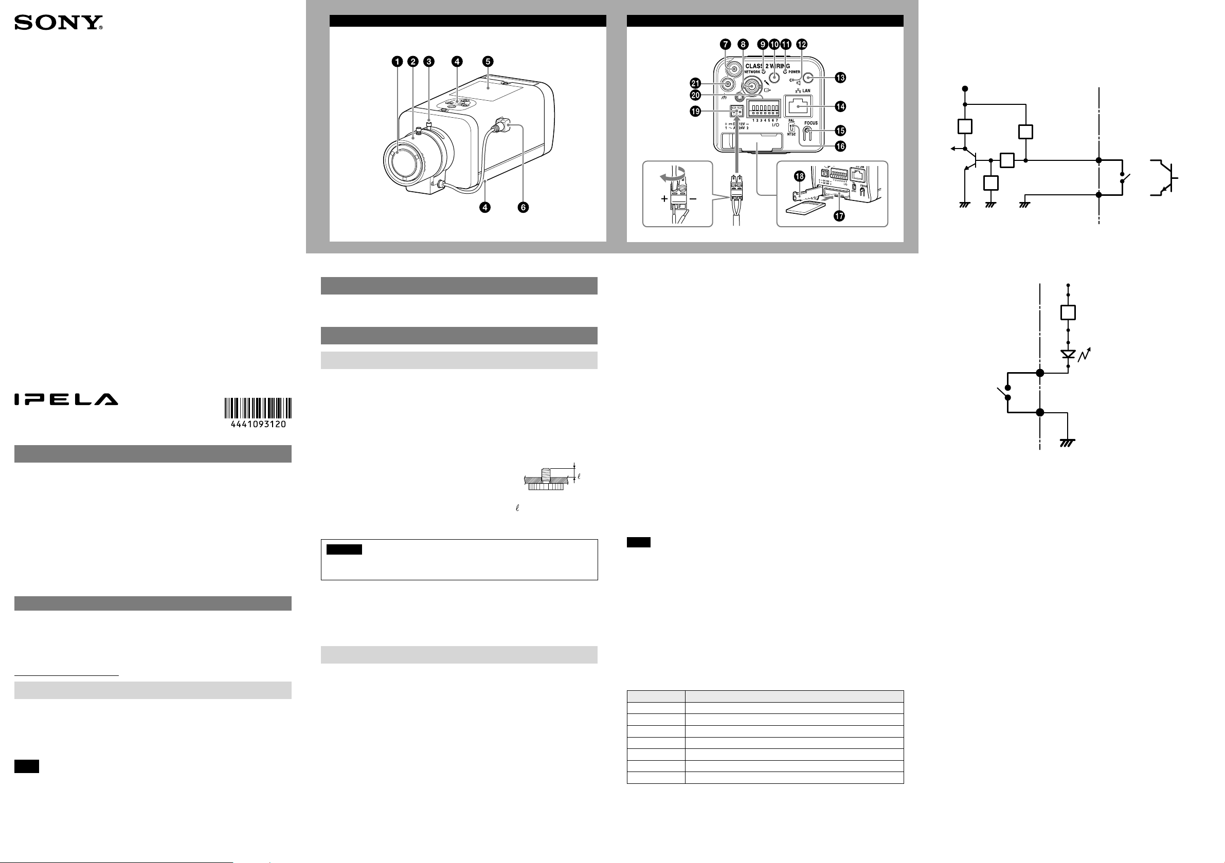
Location and Function of Part
Front
Lens
A vari-focal lens is mounted as standard equipment.
Focus ring
Turn this ring toward N (near) to focus on a closer object. Turn it toward ∞
(infinite) to focus on a farther object.
Zoom ring
Turn this ring toward T for telephoto, or toward W for wide-angle.
Tripod screw hole
Use this screw hole when attaching the camera to a
tripod (screw: 1/4”, 20 UNC). You can attach a tripod to
either the top or bottom of the camera.
Caution
Use the mounting screw whose length is 4.5 mm – 7 mm only. Use of other
screws may cause improper mounting and damage parts inside the camera.
Rating Label
This label shows the name of device and its electric rating.
Lens connector (4-pin socket)
Supplies power and control signals to an auto-iris lens.
Rear
Fall-prevention wire rope mounting screw hole
When installing the camera to the ceiling or the wall, secure the supplied wire
rope to this hole using the supplied screw.
VIDEO OUT (video output) connector
Connect the BNC cable (not supplied) to this connector.
NETWORK indicator
The indicator lights up or flashes when the camera is connected to the network.
The indicator is off when the camera is not connected to the network.
(microphone input) jack (minijack, monaural)
Connect a commercially available microphone.
This jack supports plug-in-power microphones (rated voltage: 2.5 V DC).
POWER indicator (Green)
When the power is supplied to the camera, the camera starts checking the
system. If the system is normal, this indicator lights up.
1 2
Reset switch
To reset the camera to the factory default settings, turn on the power to the
camera while holding down this switch with a pointed object.
(line output) jack (minijack, monaural)
Connect a commercially available speaker system with a built-in amplifier.
LAN network port (RJ-45)
Connect a network cable (UTP, category 5) to this port to communicate with a
network or PoE* system.
For details on connection, see the Instruction Manual of the power supply
equipment.
(*PoE stands for Power over Ethernet. It is pursuant to IEEE802.3af.)
Easy Focus button
Press this button to automatically adjust the focus.
To load the default setting, press and hold this button for 4 seconds.
NTSC/PAL switch
Switching the video output.
SD card slot
This slot is used for optional SD memory cards.
Image data in the camera can be recorded to a memory card by inserting it into
the slot.
When inserting, refer to the illustration and be sure to insert it completely. (-2)
This unit is only compatible with SD and SDHC memory cards.
Note
For inquiries regarding verified SD memory cards, contact your authorized Sony
dealer.
SD card slot cover
To remove the SD card slot cover, pull the cover forward, and insert the memory
card.
When closing the cover, be sure to close it completely by pushing on the hook
on the end until it locks in place.
DC 12 V/AC 24 V (power input) terminal
Connect to a 12 V DC or 24 V AC power supply system. (-1)
I/O (Input/Output) port
This port provides two sensor inputs and two alarm outputs.
The signal pin assignment is as follows.
PinNo. Signal
1 Sensor input 1+
2 Sensor input 2+
3 Sensor input– (GND)
4 Alarm output 1+
5 Alarm output 1–
6 Alarm output 2+
7 Alarm output 2–
For details on each function and required settings, see the User’s Guide.
2.2 k
GND
10 k
10 k
GND GND
Sensor input +
Sensor input −
(GND)
Wiring diagram for alarm output
Camera inside Outside
5 V
Alarm Output +
Magnet relay
24 V AC
24 V DC
1 A or less
Alarm Output −
(ground) terminal
This is a ground terminal for the chassis.
Circuit example
GND
Mechanical
switch
or
Open collector output
device
(continued on the reverse side)
C
1,2
3,4
5
CS-mount lens
5.5 (/) or less
Unit: mm (inch)
D
Screw (supplied)
Wire rope (supplied)
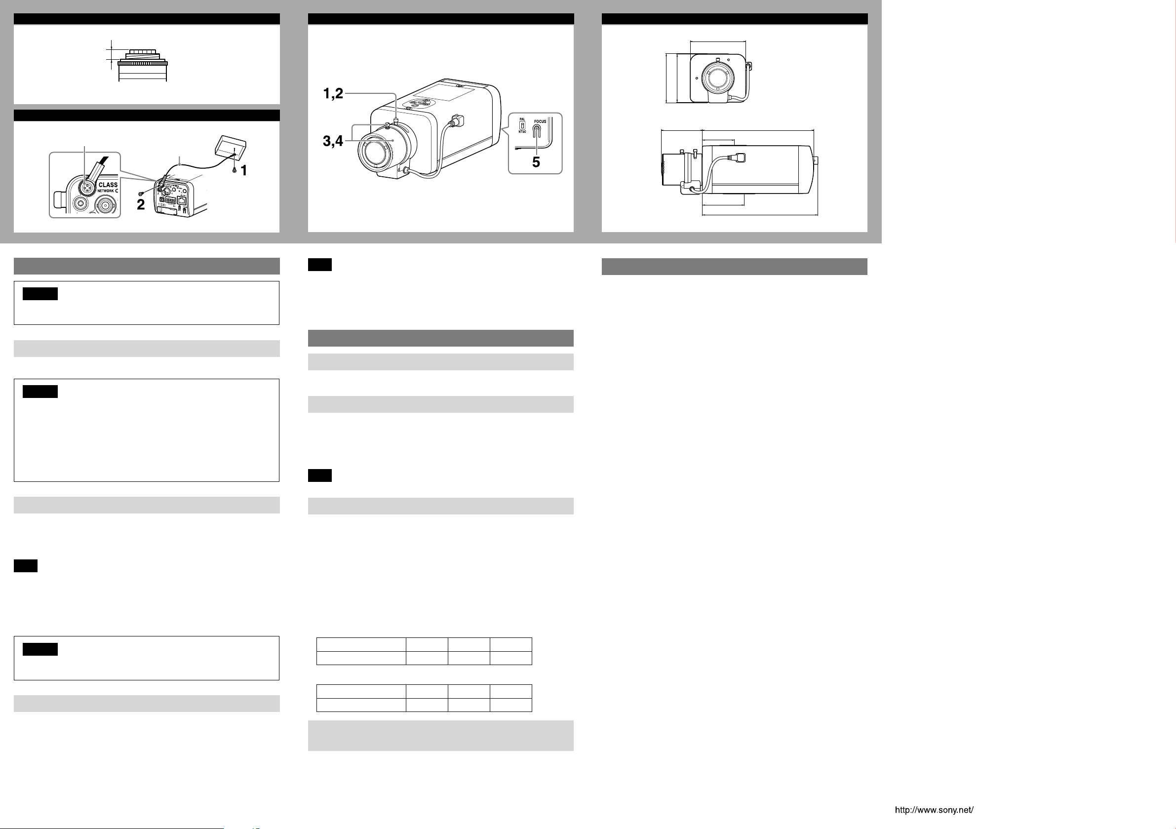
Installation
Caution
To prevent the camera from falling, make sure to attach the supplied wire
rope.
Suitable lens
The lens must be a CS-mount type and the protrusion behind the mounting
surface must be 5.5 mm (/ inch) or less.
Caution
When you install it into a wall or a ceiling, check that the wall or the ceiling ˎ
is strong enough to hold the weight of the camera including the mounting
bracket, and install it without fail. If not, the camera falls down and causes
a serious injury.
Also, check if the mounting is not loosened at least once a year. Make the
checking interval short according to use condition.
Performance will depend on the installation environment and the lens ˎ
itself. For details, contact your authorized Sony dealer.
Attaching the wire rope
When you install the camera on a ceiling or a high position, be sure to attach the
supplied wire rope to prevent the camera from falling.
Attach the wire rope to the screw hole on the rear of the camera, as in the
illustration.
Note
Take care not to short-circuit the power terminal or the cable with the wire rope
when you attach it.
1 Secure the wire rope to the junction box on the ceiling.
Use a screw to match the screw hole of your junction box (not supplied).
2 Secure the wire rope to the wire rope mounting screw hole on the rear of
the camera using the supplied screw.
Caution
Use the supplied screws for installation. If not, the wire rope may not function
properly.
Adjusting the Camera Coverage and Focus
1
Loosen the zoom ring locking screw to adjust the camera shooting
coverage.
2 Tighten the locking screw to fix the zoom.
3 Loosen the focus ring locking screw to adjust the focus.
4 Tighten the locking screw to fix the focus.
5 Press the Easy Focus button on the rear to automatically adjust the
focus.
E
Note
You may not achieve satisfactory focus with the Easy Focus button due to the
shooting environment.
In this condition, press and hold Easy Focus button for more than 4 seconds to
return to the default flange back position. Then, adjust the focus following
step 3 and 4.
Connection
Connecting to the Network
Connect the network cable of the camera to a router or hub in the network using
the network cable.
Connecting the Power Source
There are three ways to supply power to this camera, as follows.
12 V DC ˎ
24 V AC ˎ
Power supply equipment pursuant to IEEE802.3af (PoE* system) ˎ
*PoE stands for Power over Ethernet.
Note
Do not connect the power input cable if power is supplied by a PoE system.
Connecting to 12 V DC or 24 V AC source
Connect the power input cable of the camera to a 12 V DC or 24 V AC source.
Use a 12 V DC or 24 V AC source isolated from 100 to 240 V AC. The acceptable ˎ
voltage ranges for each are as follows.
12 V DC: 10.8 V to 13.2 V
24 V AC: 19.2 V to 28.8 V
- In the USA, The product shall be powered by a UL Listed Class 2 Power
Supply Only.
- In Canada, The product shall be powered by a CSA certified Class 2 Power
Supply Only.
Use UL cable (VW-1 style 10368) for these connections. ˎ
Recommended cable
12 V DC:
CABLE(AWG) #24 #22 #20
Max. length(m(feet)) 8 (26.2) 14 (45.9) 20 (65.5)
24 V AC:
CABLE(AWG) #24 #22 #20
Max. length(m(feet)) 11 (36.1) 19 (62.3) 28 (91.9)
Connecting to the power supply equipment pursuant
to IEEE802.3af
The power supply equipment pursuant to IEEE802.3af supplies the power
through the network cable. For details, refer to the Instruction Manual of the
equipment.
F
Front
Side
63 (2 /)
54.1 (2 /)
72 (2 /)
62 (2 /)
145 (5 /)
44 (1 /)
55 (2 /)
150.5 (6)
Unit: mm (inches)
Specifications
Compression
Video compression format JPEG/H.264
Audio compression format G.711/G.726/AAC
Maximum frame rate SNC-VB600/VB630
60 fps
SNC-VB600B
30 fps
Camera
Signal system NTSC color system/PAL color system
Image device SNC-VB600/VB600B
Synchronization Internal synchronization
Horizontal resolution SNC-VB600/VB600B: 600 TV lines (analog video)
Video S/N More than 50 dB (Auto gain control maximum
Minimum illumination F1.2/View-DR Off/VE* Off/Auto gain control
* VE stands for Visibility Enhancer.
Lens
Focal length 2.8 mm ~ 8 mm
Maximum relative aperture F1.2 ~ F1.95
View angle* SNC-VB600/VB600B: 1280 × 1024 (aspect ratio
* The view angle will change, depending on the setting of the aspect ratio
resolution.
Minimum object distance 300 mm
Interface
LAN (PoE) 10BASE-T/100BASE-TX, auto negotiation (RJ-45)
(switchable)
1/3type CMOS (Exmor)
Effective picture elements:
Approx. 1,370,000
SNC-VB630
1/2.9type CMOS (Exmor)
Effective picture elements:
Approx. 2,140,000
SNC-VB630: 700 TV lines (monitor display ratio
4:3)
rate 0 dB)
maximum rate MAX/50 IRE (IP)/30 fps
SNC-VB600/VB600B
Color: 0.05 lx
Black & White: 0.04 lx
SNC-VB630
Color: 0.10 lx
Black & White: 0.07 lx
5:4)
Vertical: 78.1° ~ 28.6°
Horizontal: 100.0° ~ 35.7°
SNC-VB630: 1920 × 1080 (aspect ratio 16:9)
Vertical: 60.6° ~ 22.5°
Horizontal: 114.2° ~ 40.0°
I/O port Sensor input: × 2, make contact, break contact
Alarm output: × 2, 24 V AC/DC, 1 A max.
(mechanical relay outputs electrically isolated
SD memory card slot
Video output VIDEO OUT: BNC, 1.0 Vp-p, 75 ohms,
Microphone input* Minijack (monaural)
Line input* Minijack (monaural)
* The microphone input and the line input are switchable with operating menu.
Line output Minijack (monaural), Maximum output level:
from the camera)
unbalanced, sync negative
Plug-in-power supported (rated voltage: 2.5 V
DC)
Recommended load impedance: 2.2 k
1 Vrms
Others
Power supply 12 V DC ± 10%
24 V AC ± 20%, 50 Hz/60 Hz
Power consumption 6.0 W max.
Operating temperature Start temperature: 0°C to 50°C (32°F to 122°F)
Storage temperature –20°C to +60°C (–4°F to +140°F)
Operating humidity 20% to 80%
Storage humidity 20% to 95%
Dimensions (w/h/d)
Mass Approx. 565 g (1 lb 3.9 oz) with lens
Supplied accessories CD-ROM (Supplied programs) (1)
Design and specifications are subject to change without notice.
IEEE802.3af compliant (PoE system)
Working temperature: –10°C to +50°C
(14°F to 122°F)
72 mm × 63 mm × 145 mm (2
2 1/2 inches × 5 3/4 inches) not including the
projecting parts and lens
Wire rope (1)
Screw M4 (1)
DC 12 V/AC 24 V connector (1)
Safety Regulations (1)
Installation Manual (this document) (1)
7
/8 inches ×
 Loading...