

Sony SDM-P82B Operating Instructions Manual
4-090-729-11(2)
TFT LCD Color
Computer Display
Operating Instructions
Mode d’emploi
Manual de instrucciones
US
FR
ES
SDM-P82
© 2002 Sony Corporation
Owner’s Record
The model and serial numbers are located at the rear of the unit.
Record these numbers in the spaces provided below. Refer to them
whenever you call upon your dealer regarding this product.
Model No.
Serial No.
WARNING
To prevent fire or shock hazard, do not ex pose the
unit to rain or moisture.
Dangerously high voltages are present inside the
unit. Do not open the cabinet. Refer servicing to
qualified personnel only.
FCC Notice
This equipment has been tested and found to comply with the limits
for a Class B digital device, pursuant to Part 15 of the FCC Rules.
These limits are designed to provide reasonable protection against
harmful interference in a residential installation. This equipment
generates, uses, and can radiate radio frequency energy and, if not
installed and used in accordance with the instructions, may cause
harmful interference to radio communications. However, there is no
guarantee that interference will not occur in a particular installation.
If this equipment does cause harmful interference to radio or
television reception, which can be determined by turning the
equipment off and on, the user is encouraged to try to correct the
interference by one or more of the following measures:
– Reorient or relocate the receiving antenna.
– Increase the separation between the equipment and receiver.
– Connect the equipment into an outlet on a circuit different from
that to which the receiver is connected.
– Consult the dealer or an ex perienced r adio/TV te chnician f or help.
You are cautioned that any changes or modifications not expressly
approved in this manual could void your authority to operate this
equipment.
If you have any questions about this product, you may call:
Sony Customer Information Center
1-800-222-SONY (7669)
or write to:
Sony Customer Information Center
1 Sony Drive, Mail Drop #T1-11, Park Ridge, NJ 07656
NOTICE
This notice is applicable for USA/Canada only.
If shipped to USA/Canada, install only a UL LISTED/CSA
LABELLED power supply cord meeting the following
specifications:
SPECIFICATIONS
Plug Type Nema-Plug 5-15p
Cord Type SVT or SJT, minimum 3
Length Maximum 15 feet
Rating Minimum 7 A, 125 V
× 18 AWG
NOTICE
Cette notice s’applique aux Etats-Unis et au Canada
uniquement.
Si cet appareil est exporté aux Etats-Unis ou au Canada, utiliser
le cordon d’alimentation portant la mention UL LISTED/CSA
LABELLED et remplissant les conditions suivantes:
SPECIFICA TIONS
Type de fiche Fiche Nema 5-15 broches
Cordon Type SVT ou SJT, minimum 3
Longueur Maximum 15 pieds
Tension Minimum 7 A, 125 V
As an
NERGY STAR Partner, Sony
E
Corporation has determined that this
product meets the
guidelines for energy efficiency.
This monitor complies with the
TCO’95 guidelines.
× 18 AWG
NERGY STAR
E
Declaration of Conformity
Trade Name: SONY
Model No.: SDM-P82
Responsible Party: Sony Electronics Inc.
Address: 680 Kinderkamack Road,Oradell,NJ 07649
Telephone No.: 201-930-6972
This device complies with Part 15 of the FCC Rules. Operation is
subject to the following two conditions: (1) This device may not
cause harmful interference, and (2) this device must accept any
interference received, including interference that may cause
undesired operation.
USA
2
Table of Contents
Precautions. . . . . . . . . . . . . . . . . . . . . . . . . . . . . . . . . . . . . . . . . . . . 4
Identifying parts and controls . . . . . . . . . . . . . . . . . . . . . . . . . . . . . . 5
Setup. . . . . . . . . . . . . . . . . . . . . . . . . . . . . . . . . . . . . . . . . .7
Setup 1: Connect a computer equipped with the DVI output
connector (digital RGB) . . . . . . . . . . . . . . . . . . . . . . . . . . . . 7
Setup 2: Connect a computer equipped with the HD15 output
connector (analog RGB). . . . . . . . . . . . . . . . . . . . . . . . . . . . 7
Setup 3: Connect the power cord . . . . . . . . . . . . . . . . . . . . . . . . . . 8
Setup 4: Bundle the cords and cables. . . . . . . . . . . . . . . . . . . . . . . 9
Setup 5: Turn on the monitor and computer . . . . . . . . . . . . . . . . . . 9
Setup 6: Adjusting the tilt . . . . . . . . . . . . . . . . . . . . . . . . . . . . . . . . 10
Selecting the input signal (INPUT button)
. . . . . . . . . . . . . . . . . 11
Custo mizing Y our Mo nitor . . . . . . . . . . . . . . . . . . . . . . .11
Navigating the menu. . . . . . . . . . . . . . . . . . . . . . . . . . . . . . . . . . . . 11
BACKLIGHT. . . . . . . . . . . . . . . . . . . . . . . . . . . . . . . . . . . . . . . 12
CONTRAST . . . . . . . . . . . . . . . . . . . . . . . . . . . . . . . . . . . . . . . . 12
BRIGHTNESS . . . . . . . . . . . . . . . . . . . . . . . . . . . . . . . . . . . . . 12
SCREEN (analog RGB signal only) . . . . . . . . . . . . . . . . . . . . . 12
COLOR . . . . . . . . . . . . . . . . . . . . . . . . . . . . . . . . . . . . . . . . . . . 14
GAMMA . . . . . . . . . . . . . . . . . . . . . . . . . . . . . . . . . . . . . . . . . . . 15
ZOOM . . . . . . . . . . . . . . . . . . . . . . . . . . . . . . . . . . . . . . . . . . . . 15
SMOOTHING. . . . . . . . . . . . . . . . . . . . . . . . . . . . . . . . . . . . . . 15
Additional settings. . . . . . . . . . . . . . . . . . . . . . . . . . . . . . . . . . . . . . 16
US
• Macintosh is a trademark licensed to
Apple Computer, Inc., registered in the
U.S.A. and other count r ies.
• Windows
Microsoft Corporation in the United
States and other countries.
• IBM PC/AT and VGA are registered
trademarks of IBM Corporation of the
U.S.A.
• VESA and DDC
Video Electronics Standards
Association.
E
•
mark.
• All other product na mes mentioned
herein may be the trademarks or
registered trade marks of their respecti ve
companies.
•Furthermore, “
mentioned in each case in this manual.
is registered trademark of
are trademarks of the
NERGY STAR is a U.S. registered
” and “” are not
Techn ic a l Feature s . . . . . . . . . . . . . . . . . . . . . . . . . . . . .17
Power saving function. . . . . . . . . . . . . . . . . . . . . . . . . . . . . . . . . . . 17
Reducing the power consumption (ECO mode) . . . . . . . . . . . . . . . 17
Automatic picture quality adjustment function
(analog RGB signal only) . . . . . . . . . . . . . . . . . . . . . . . . . . . . . . . . 17
Troub le s h ooting. . . . . . . . . . . . . . . . . . . . . . . . . . . . . . . .18
On-screen messages . . . . . . . . . . . . . . . . . . . . . . . . . . . . . . . . . . . 18
Trouble symptoms and remedies . . . . . . . . . . . . . . . . . . . . . . . . . . 19
Self-diagnosis function . . . . . . . . . . . . . . . . . . . . . . . . . . . . . . . . . . 21
Specific a t io ns. . . . . . . . . . . . . . . . . . . . . . . . . . . . . . . . . .21
TCO’95 Eco-document . . . . . . . . . . . . . . . . . . . . . . . . . . . . . . . . . . . .i
3
Precautions
Warning on power connections
• Usethe supplied power cord. If you use a different power cord,
be sure that it is compatible with your local power supply.
For the customers in the U.S.A.
If you do not use the appropriate cord, this monitor will not
conform to mandatory FCC standards.
For the customers in the UK
If you use the monitor in the UK, be sure to use the appropriate
UK power cord.
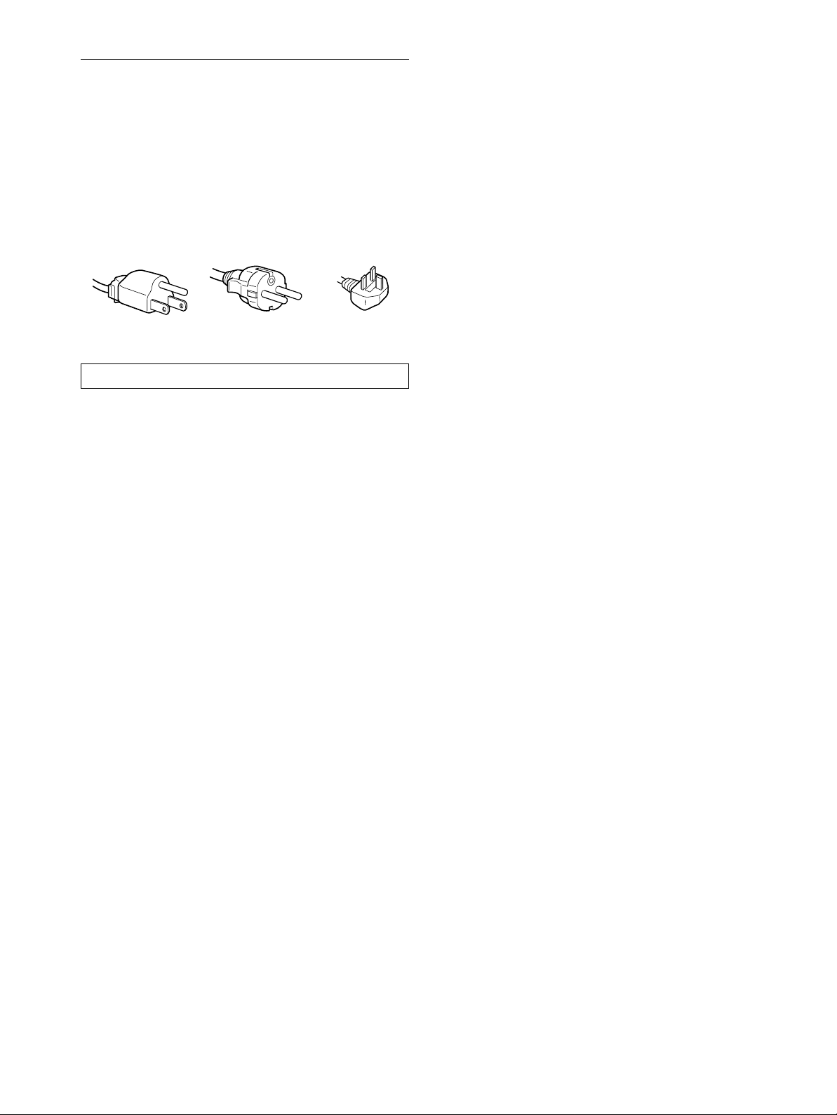
Example of plug types
for 100 t o 120 V AC for 200 to 240 V AC for 240 V AC only
The equipment should be installed near an easily accessible outlet.
Installation
Do not install or leave the monitor:
• In places subject to extreme temperatures, for example near a
radiator, heating vent, or in direct sunlight. Subjecting the
monitor to extreme temperatures, such as in an automobile
parked in direct sunlight or near a heating vent, could cause
deformations of the casing or malfunctions.
• In places subject to mechanical vibration or shock.
• Near any equipment that generates a strong magnetic field,
such as a TV or various other household appliances.
• Inplaces subject to inordinate amounts of dust, dirt, or sand, for
example near an open window or an outdoor exit. If setting up
temporarily in an outdoor environment, be sure to take
adequate precautions against airborne dust and dirt. Otherwise
irreparable malfunctions could occur.
Handling the LCD screen
• Do not leave the LCD screen facing the sun as it can damage
theLCDscreen.Takecarewhenyouplacethemonitorbya
window.
• Donot push onor scratch the LCD screen. Do not place a heavy
object on the LCD screen. This may cause the screen to lose
uniformity or cause LCD panel malfunctions.
• If the monitor is used in a cold place, a residual image may
appear on the screen. This is not a malfunction. The screen
returns to normal as the temperature rises to a normal operating
level.
• If a still picture is displayed for a long time, a residual image
may appear for a while. The residual image will eventually
disappear.
• The LCD panel becomes warm during operation. This is not a
malfunction.
Note on the LCD (Liquid Crystal Display)
Please note that the LCD screen is made with high-precision
technology. However, black points or bright points of light (red,
blue, or green) may appear constantly on the LCD screen, and
irregular colored stripes or brightness may appear on the LCD
screen.Thisisnotmalfunction.
(Effective dots: more than 99.99%)
Replacement of the fluorescent tube
A specially designed fluorescent tube is installed as the lighting
apparatus for this monitor. If the screen becomes dark, unstable,
or does not turn on, replace the fluorescent tube with a new one.
Consult your Sony dealer when replacing the fluorescent tube.
Maintenance
• Be sure to unplug the power cord from the power outlet before
cleaning your monitor.
• CleantheLCDscreenwithasoftcloth.Ifyouuseaglass
cleaning liquid, do not use any type of cleaner containing an
anti-static solution or similar additive as this may scratch the
LCD screen’s coating.
• Clean the cabinet, panel, and controls with a soft cloth lightly
moistened with a mild detergent solution. Do not use any type
of abrasive pad, scouring powder, or solvent, such as alcohol or
benzine.
• Do not rub, touch, or tap the surface of the screen with sharp or
abrasive items such as a ballpoint pen or screwdriver. This type
of contact may result in a scratched picture tube.
• Note that material deterioration or LCD screen coating
degradation may occur if the monitor is exposed to volatile
solvents such as insecticide, or if prolonged contact is
maintained with rubber or vinyl materials.
Transportation
• Disconnect all cables from the monitor and grasp the support
and base sections of the display stand firmly with both hands
whentransporting.If you drop the monitor, you may be injured
or the monitor may be damaged.
• Whenyou transport this monitor for repair or shipment, use the
original carton and packing materials.
Disposal of the monitor
• Do not dispose of this monitor with general
household waste.
• The fluorescent tube used in this monitor contains
mercury.Disposal of thismonitor must becarried out
in accordance to the regulations of your local
sanitation authority.
4
Identifying parts and controls
See the pages in parentheses for further details.
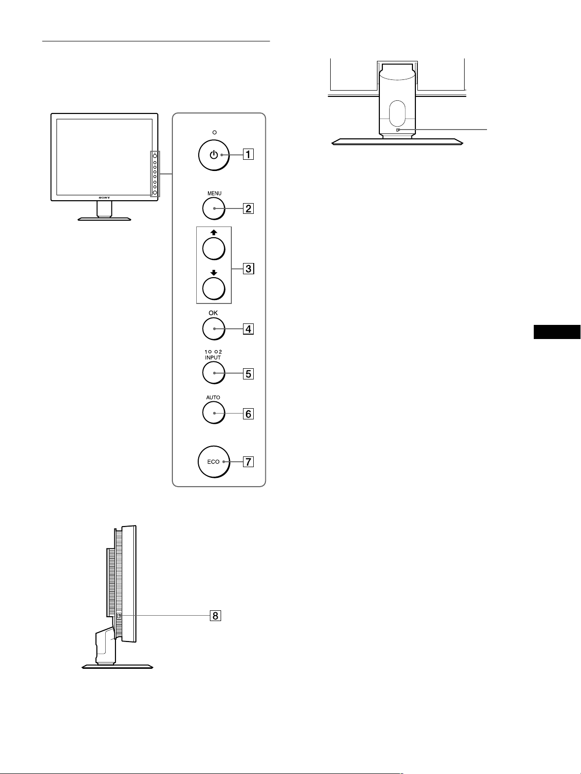
Front of the LCD display
Rear of the display stand
9
AAAA 1 (Power) switch and 1 (Power) indicator
(pages 9, 17, 21)
This switch turns the monitor o n when the 1 (power)
indicator lights up in red. To turn the monitor off, press this
switch again.
If the 1 (power) indicator does not light up, press the MAIN
POWER switch (8).
BBBB MENU button (page 11)
This button turns the menu screen on and off.
CCCC M/m buttons (page 11)
These buttons are used to select the menu items and make
adjustments.
Side view of the LCD display
DDDD OK button (page 11)
This button activates the se lected menu item and adjustments
using with M/m buttons (3).
EEEE INPUT button and INPUT1/INPUT2 indicator
(page 11)
This button selects the connected computer for switching the
video input signals, and the corresponding indicator,
(INPUT1 or INPUT2) lights up.
FFFF AUTO button (page 12)
Press this button when the displayed picture seems poorly
adjusted. It makesfurther automatic adjustment ofthe picture
quality for the current input signal.
GGGG ECO button (page 17)
Thisbuttonisusedtoreducethepowerconsumption.
HHHH MAIN POWER switch (page 9)
This switch turns the monitor’s main power on and off.
IIII Security Lock Hole
The security lock hole should be applied with the Kensington
Micro Saver Security System.
Micro Saver Security System is a trademark of Kensington.
US
(continued)
5
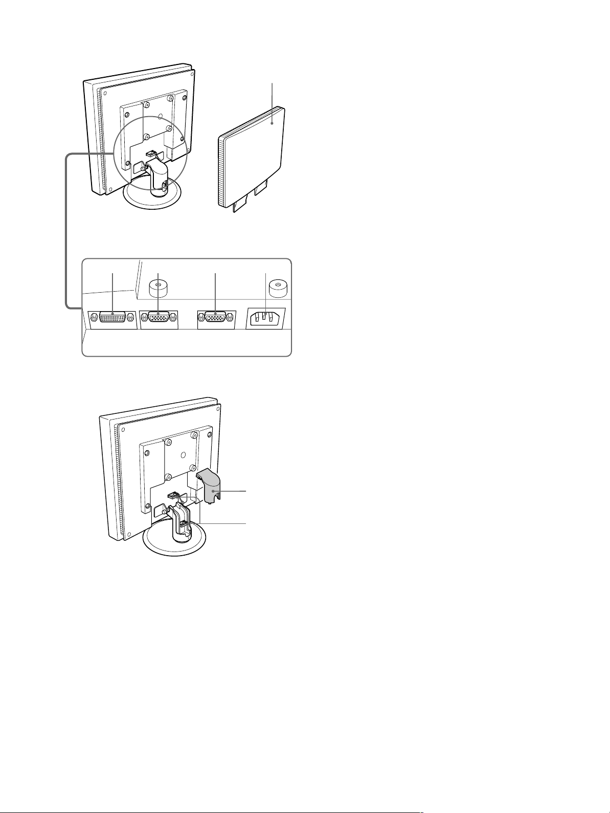
Rear of the LCD display
JJJJ Back cover (page 7)
Remove this cover when you connect cables or cords.
qa qs qd qf
q;
KKKK DVI-D input connector (digital RGB) for INPUT1
(page 7)
This connector inputs digital RGB video signals that comply
with DVI Rev. 1.0.
LLLL HD15 input connector (analog RGB) for INPUT1
(page 7)
Thisconnectorinputs analogRGB videosignals(0.700Vp-p,
positive) and sync signals.
MMMM HD15 input connector (analog RGB) for INPUT2
(page 7)
Thisconnectorinputs analogRGB videosignals(0.700Vp-p,
positive) and sync signals.
NNNN AC IN connector (page 8)
Connect the power cord (supplied).
OOOO Arm cover (page 9)
Remove this cover to bundle c onnecting cords and cables.
PPPP Cable holder (page 9)
This part secures cables and cords to the monitor.
qg
qh
6
Setup
Before using your monitor, check that the following items are
included in your carton:
• LCD display
• Power cord
• HD15-HD15 video signal cable (analog RGB)
• DVI-D video signal cable (digital RGB)
• Windows Utility/Macintosh Utility Disk
• Warranty card
• This instruction manual
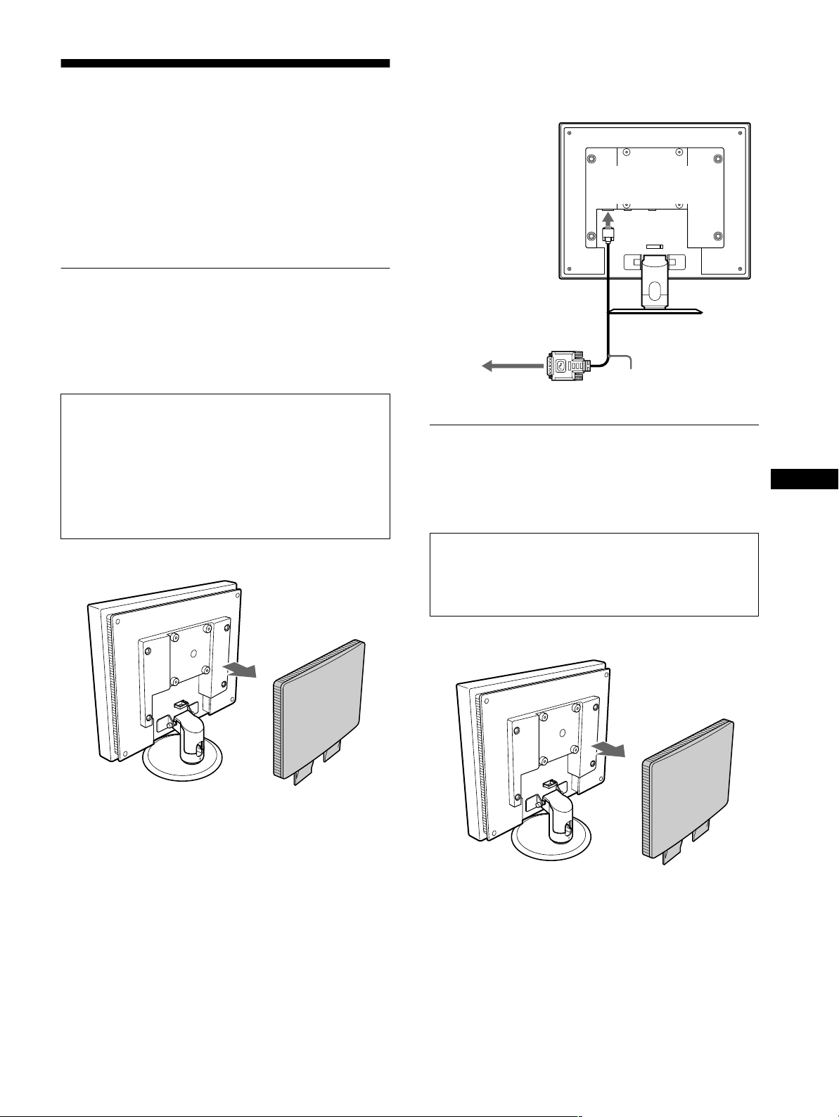
Setup 1:Connect a computer
equipped with the DVI
output connector (digital
RGB)
• Turnoff the monitor and computer before connecting.
• Whenconnecting the computer to the monitor’s HD15
input connector (analog RGB), refer to “Setup 2:
Connect a computer equipped with the HD15 output
connector (analog RGB).”
Note
Do not touch the pins of the video signal cable connector as this might
bend the pins.
1 Remove the back cover.
2 Using the supplied DVI-D video signal cable (digital
RGB), connect the computer to the monitor’sDVI-D
input connector (digital RGB) for INPUT1.
to the DVI-D input
connector (digital
RGB) for INPUT1
to the computer’s DVI output
connector (digital RGB)
DVI-D video signal cable
(digital RGB) (supplied)
Setup 2:Connect a computer
equipped with the HD15
output connector (analog
RGB)
Turn off the monitor and computer before connecting.
Note
Do not touch the pins of the video signal cable connector as this might
bend the pins.
US
1 Remove the back cover.
(continued)
7
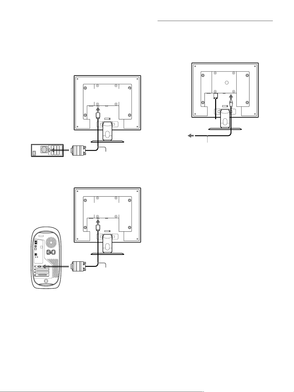
2 Using the supplied HD15-HD15 video signal cable
(analog RGB), connect the computer to the
monitor’s HD 15 input connector (analog RGB) for
INPUT 1 or INPUT2.
Connect the computer according to the following
illustrations.
Connecting to an IBM PC/AT or
xxxx
compatible computer
Setup 3:Connect the power cord
1 Connect the supplied power cord to the monitor’s
AC IN connector.
2 Connect it to a power outlet.
to the computer’s HD15 output
connector (analog RGB)
IBM PC/AT or
compatible computer
Connecting to a Macintosh
xxxx
to the HD 15 input
connector(analogRG B)
for INPUT1 or INPUT2
HD15-HD15 video signal
cable (analog RGB)
(supplied)
to the HD 15 input
connector(analogRG B)
for INPUT1 or INPUT2
to AC IN
1
to power outlet
power cord (supplied)
2
to the computer’s
output connector
Macintosh
When connecting a Macintosh computer, use an adapter (not supplied)
if necessary. Connect the adapter to the computer before connecting the
video signal cable.
HD15-HD15 video signal
cable (analog RGB)
(supplied)
8
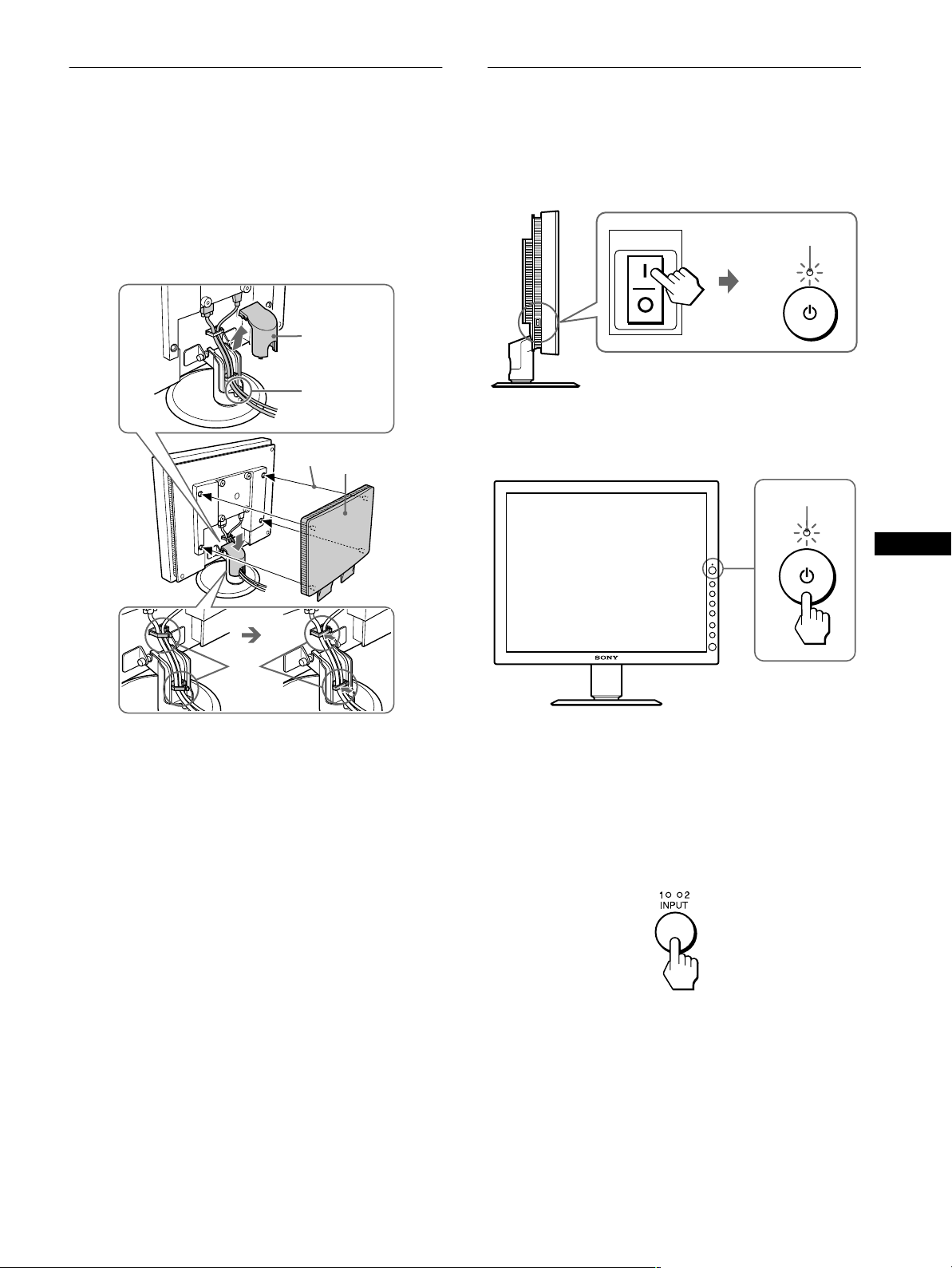
Setup 4:Bundle the cords and
Setup5:Turnonthemonitorand
cables
1 Remove the arm cover.
2 Bundle the cords and cables inside of the stand.
3 Secure the cables and cords with the cable holder.
4 Replace the arm cover and back cover.
1
arm cover
2
4
back cover
computer
1 PresstheMAIN POWER switchon the leftside of the
monitor in the direction of [.
The 1 (power) indicator lights up in red.
MAIN POWER
2 Press the 1 (power) switch on the front right of the
monitor.
The 1 (power) indicator lights up in green.
lights in red
lights in green
US
3
Note
If you cannot bundle all of the cords and cables inside the stand, leave
them hanging down outside the stand.
3 Turn on the computer.
4 Press the INPUT button repeatedly and select the
desired input signal.
The selected input signal indicator lights up and the picture
appears on the screen.
Formoreinformation,see “Selecting the inputsignal(INPUT
button)” on page 11.
The installation of your monitor is complete. If necessary, use the
monitor’s controls to adjust the picture (page 11).
(continued)
9
If no picture appears on your s creen
• Checkthat the power cord and the video signal cable are
properly connected.
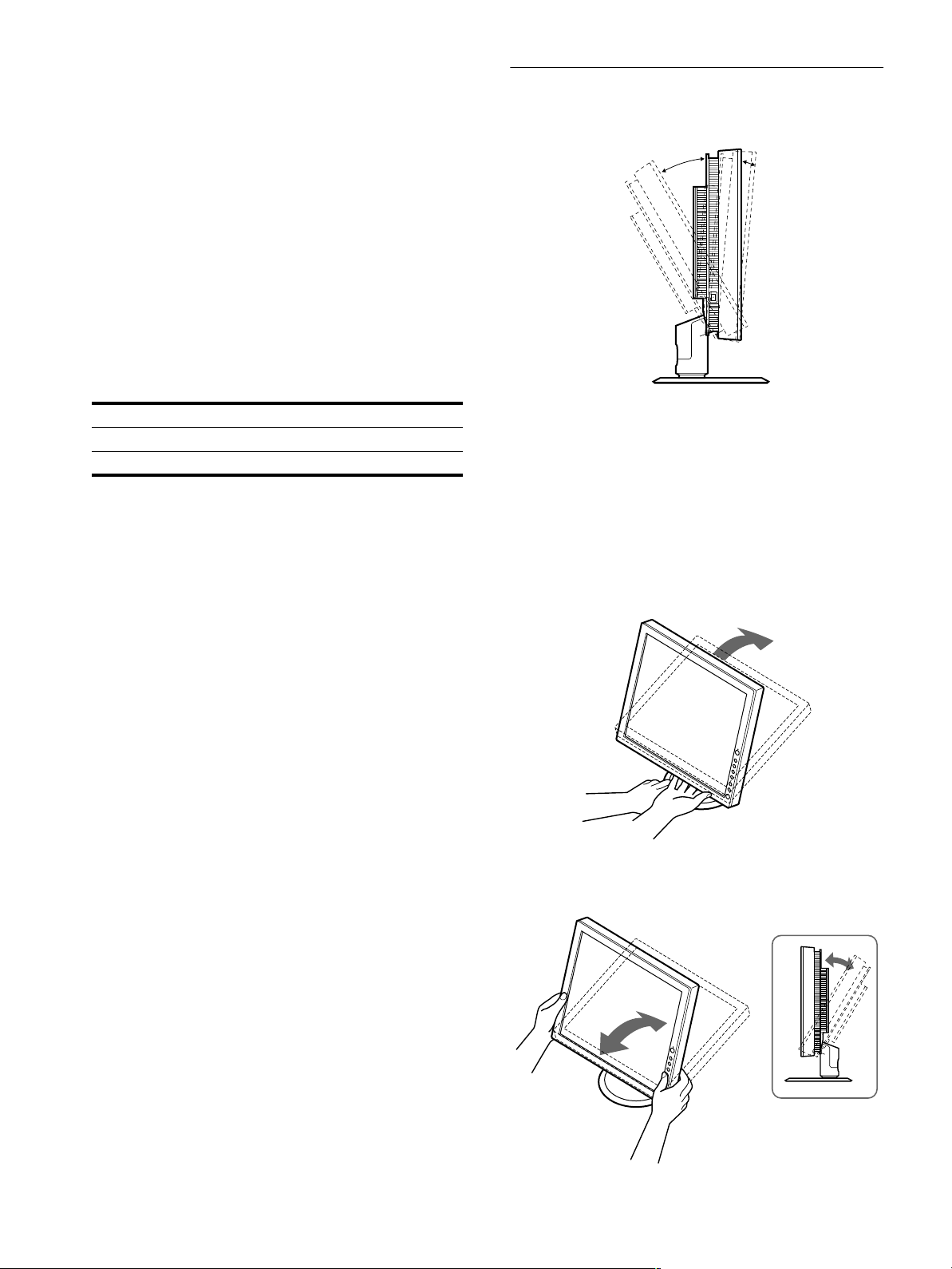
Setup 6:Adjusting the tilt
This monitor can be adjusted within the angles shown below.
• If NO INPUT SIGNAL appears on the screen:
– The computer is in the power saving mode. Try pressing any
key on the keyboard or moving the mouse.
– Check that the input signal setting is correct by pressing the
INPUT button repeatedly (page 11).
• If CABLE DISCONNECTED appears on the screen:
– Check that the video signal cable is properly connected.
– Check that the input signal setting is correct by pressing the
INPUT button repeatedly (page 11).
• If OUT OF SCAN RANGE appears on the screen, reconnect
the old monitor. Then adjust the computer’sgraphicsboardin
the following ranges.
Horizontal frequency 28 – 92 kHz
Vertical frequency 56 – 85 Hz
Resolution 1280 × 1024 or less
For more information about on-screen messages, see “Trouble
symptoms and remedies” on page 19.
No need for specific drivers
The monitor complies with the “DDC” Plug & Play standard and
automaticallydetects all the monitor’s information. No specific driver
needs to be installed to the computer.
The first time you turn on your computer after connecting the monitor, the
setup Wizard may appear on the screen. In this case, follow the on-screen
instructions. The Plug & Play monitor is automatically selected so that
you can use this monitor.
20°
5°
To use the monitor comfortably
Adjust the viewing angle of your monitor according to the height
of your desk and chair, and so that light is not reflected from the
screen to your eyes.
Note
When adjusting the screen tilt, proceed slowly and carefully, being sure
not to hit the monitor against the desk or the base of the display stand.
1 Grasp the lower middle part of the LCD panel while
holding the display stand, then, tilt the LCD panel
adequately backward.
The vertical frequency turns to 60 Hz.
Since flickers are unobtrusive on the monitor, you can use it as it is. You
do not need to set the vertical frequency to any particular high value.
2 Grasp the lower sides of the LCD panel, then adjust
screen tilt.
10
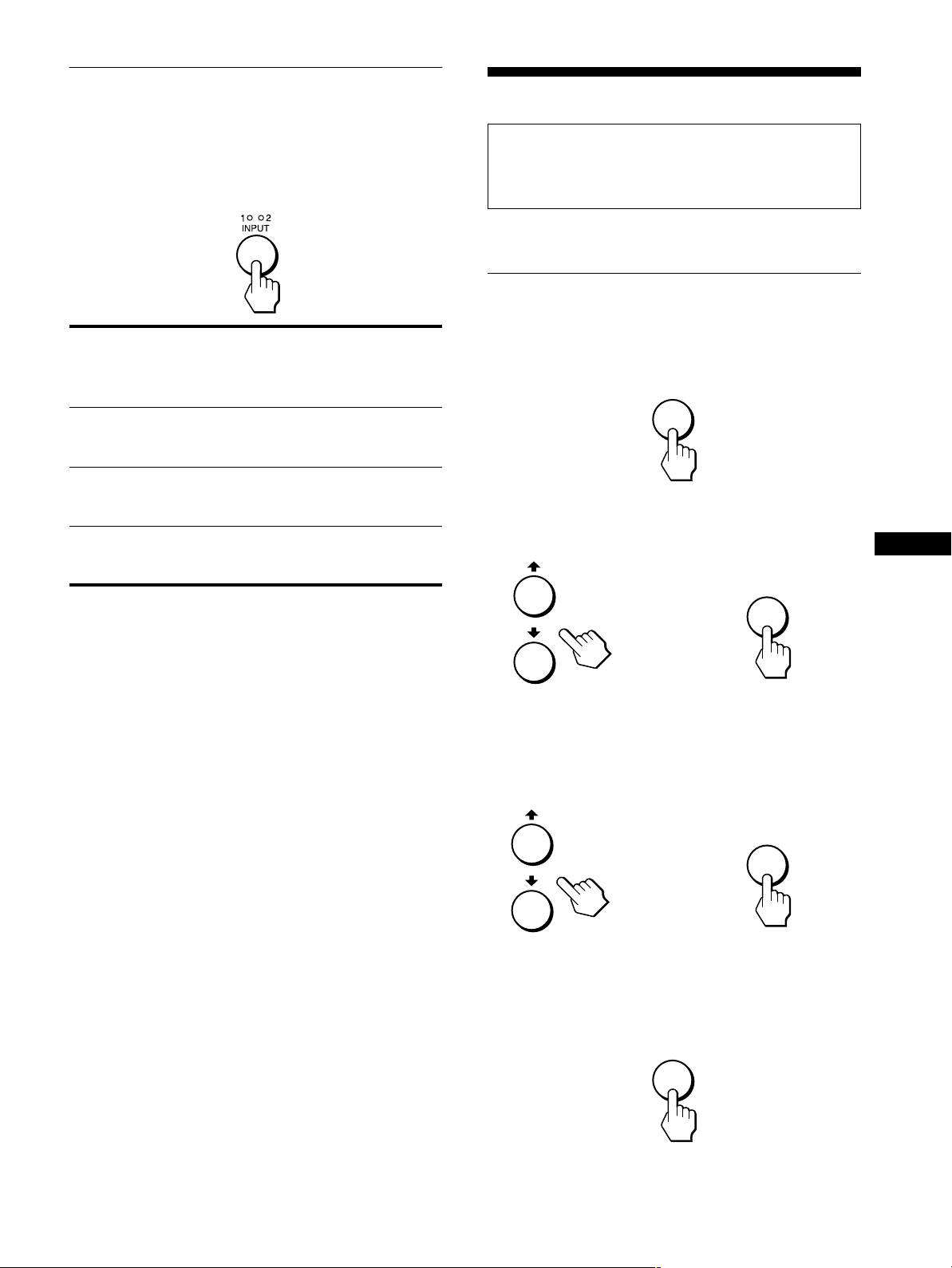
Selecting the input signal
(INPUT button)
Customizing Your Monitor
Press the INPUT button.
The input signal change each time you press this button as
follows.
On-screen
message)
(Appears about 5
seconds on the
upper left corner.)
INPUT1: DVI-D INPUT1 DVI-D input
INPUT1: HD15 INPUT1 HD15 input
INPUT2: HD15 INPUT2 HD15 input
Input indicator
lights up
Input signal
configuration
connector (digital
RGB) for INPUT1
connector (analog
RGB) for INPUT1
connector (analog
RGB) for INPUT2
Before making adjustments
Connect the monitor and the computer, and turn them on.
Wait for at least 30 minutes before making adjustments for the
best results.
You can make numerous adjustments to your monitor using the
on-screenmenu.
Navigating the menu
1 Display the main menu.
Press the MENU button to display the main menu on your
screen.
MENU
2 Select the menu you want to adjust.
Press the M/m buttons to display the desired menu. Press the
OK button to select the menu item.
OK
US
,
3 Adjust the menu.
Press the M/m buttons to make the adjustment, then press the
OK button.
When you press the OK button, the setting is stored, then the
display returns to the previous menu.
OK
,
4 Close the menu.
Press the MENU button once to return to normal viewing. If
no buttons a re pressed, the menu closes automatically after
about 45 seconds.
MENU
11
Resetting the adjustments to the default
xxxx
settings
You can reset the adjustments using the RESET menu. For more
information about resetting the adjustments, see “0 (RESET)”
on page 16.
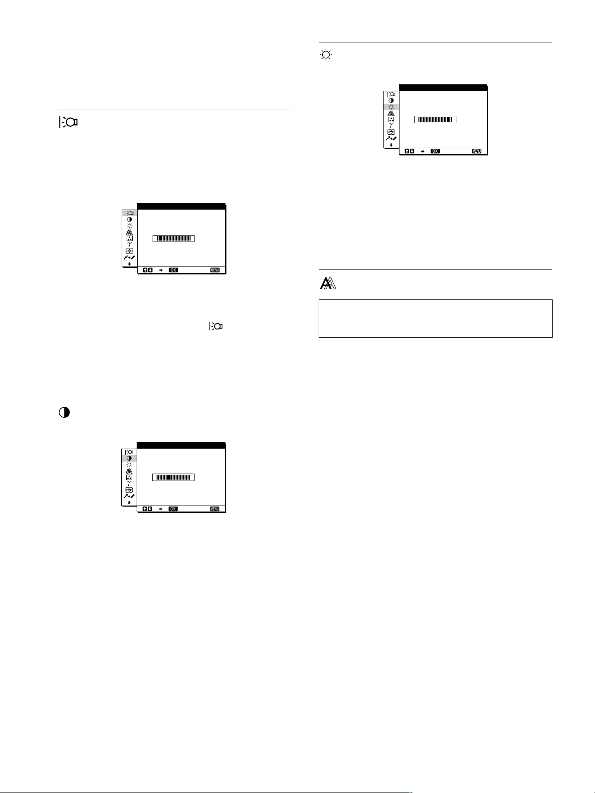
BRIGHTNESS
Adjust the picture brightness (black level).
BR GHTNESSI
BACKLIGHT
Ifthescreenis toobright, adjust the backlightand makethe screen
easier to see.
Note
The backlight cannot be adjusted when the ECO mode is set to “ON”
(page 17).
BACKL GHTI
100
1280 1024 60Hzx/
EX I T
1 Press the MENU button.
The main menu appears on the screen.
2 Press the M/m buttons to select (BACKLIGHT)
and press the OK button.
The BACKLIGHT menu appears on the screen.
3 Press the M/m buttons to adjust the desired light
level.
CONTRAST
Adjust the picture contrast.
CONTRAST
100
1280 1024 60Hzx/
1 Press the MENU button.
The main menu appears on the screen.
2 Press the M/m buttons to select 6 (CONTRAST) and
press the OK button.
The CONTRAST menu appears on the screen.
EX I T
100
1280 1024 60Hzx/
EX I T
1 Press the MENU button.
The main menu appears on the screen.
2PresstheM/m buttons to select 8 (BRIGHTNESS)
and press the OK button.
The BRIGHTNESS menu appears on the screen.
3PresstheM/m buttons to adjust the brightness.
SCREEN
Note
When receiving digital RGB signals from the DVI-D input connector
for INPUT1, adjustment is unnecessary.
Automatic picture quality adjustment
xxxx
(analog RGB signal only)
function
When the monitor receives an input signal, it
automatically adjusts the picture’s position and
sharpness (phase/pitch), and ensures that a clear
picture appears on the screen (page 17).
Note
While the automatic picture quality adjustment function is activated, only
(power) switch will operate.
the
1
If the automatic picture quality adjustment function of
this monitor seems to not completely adjust the picture
By pressing the AUTO button, you can make further automatic
adjustment of the picture quality for the current input signal
(page 5).
If you still need to make further adjustments to the
picture quality
Youcanmanuallyadjustthepicture’s sharpness(phase/pitch)and
position (horizontal/vertical position).
3 Press the M/m buttons to adjust the contrast.
12
If you need to eliminate a shift of the picture occurring
when the input signal has been changed
The shift is caused by the a utomatic picture quality adjustment
function. You can deactivate this function (page 14).
These adjustments are stored in memory and automatically
recalledwhen the display receivesthe same input signal.
SCREEN
PHASE
P I TCH
H CENTER
V CENTER
AUTO
ON
1280 1024 60Hzx/
Adjust the picture’s sharpness manually
xxxx
EX I T
(PHASE/PITCH)
You can adjust the picture’s sharpness as follows. This
adjustment is effective when the computer is connected to the
monitor’s HD15 input connector (analog RGB).
1 Set the resolution to 1280 × 1024 on the computer.
2 Load the Utility Disk.
3 Start the Utility Disk and display the test pattern.
For Windows
[Windows]/[Win Utility.exe].
Click [Utility]
For Macintosh
Click [Utility]
t
t [Mac]/[Mac Utility].
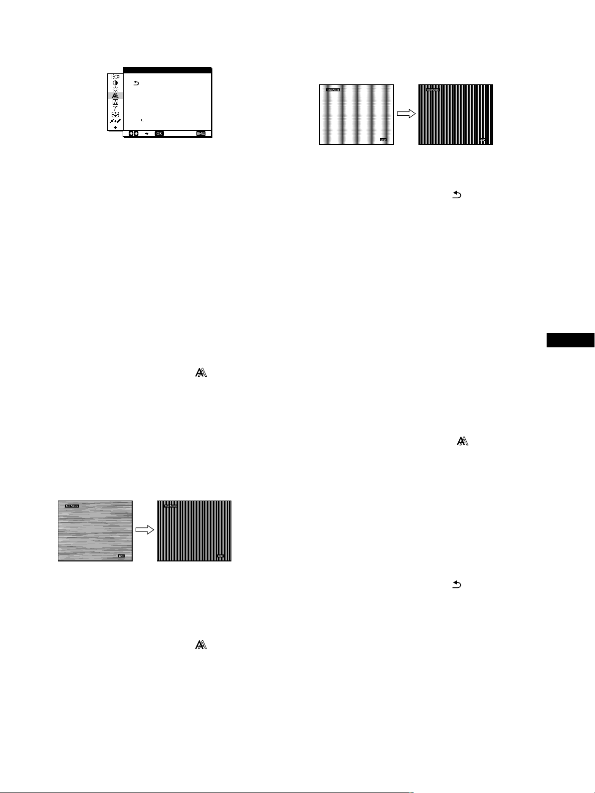
11 Press the M/m buttons until the vertical stripes
disappear.
Adjust so that the vertical stripes disappear.
12 Click [END] on the screen to turn off the test pattern.
13 Press the M/m buttonsto select and press the OK
button.
Return to the menu screen.
Adjust the picture’s position manually
xxxx
(H CENTER/V CENTER)
If the picture is not in the center of the screen, adjust the picture’s
centering as follows.
1 Set the resolution to 1280 × 1024 on the computer.
2 Load the Utility Disk.
4 Press the MENU button.
The main menu appears on the screen.
5 Press the M/m buttons to select (SCREEN) and
press the OK button.
The SCREEN menu appears on the screen.
6 Press the M/m buttons to select PHASE and press
the OK button.
The PHASE menu appears on the screen.
7 Press the M/m buttons until the horizontal stripes
are at a minimum.
Adjust so that the horizontal stripes are at a minimum.
8 Press the OK button.
The main menu appears on the screen.
If vertical stripes are observed over the entire screen, adjust
pitch by the following steps.
3 Start the Utility Disk and display the test pattern.
For Windows
[Windows]/[Win Utility.exe].
Click [Utility]
t
For Macintosh
Click [Utility]t[Mac]/[Mac Utility].
4 Press the MENU button.
The main menu appears on the screen.
5 Press the M/m buttons to select (SCREEN) and
press the OK button.
The SCREEN menu appears on the screen.
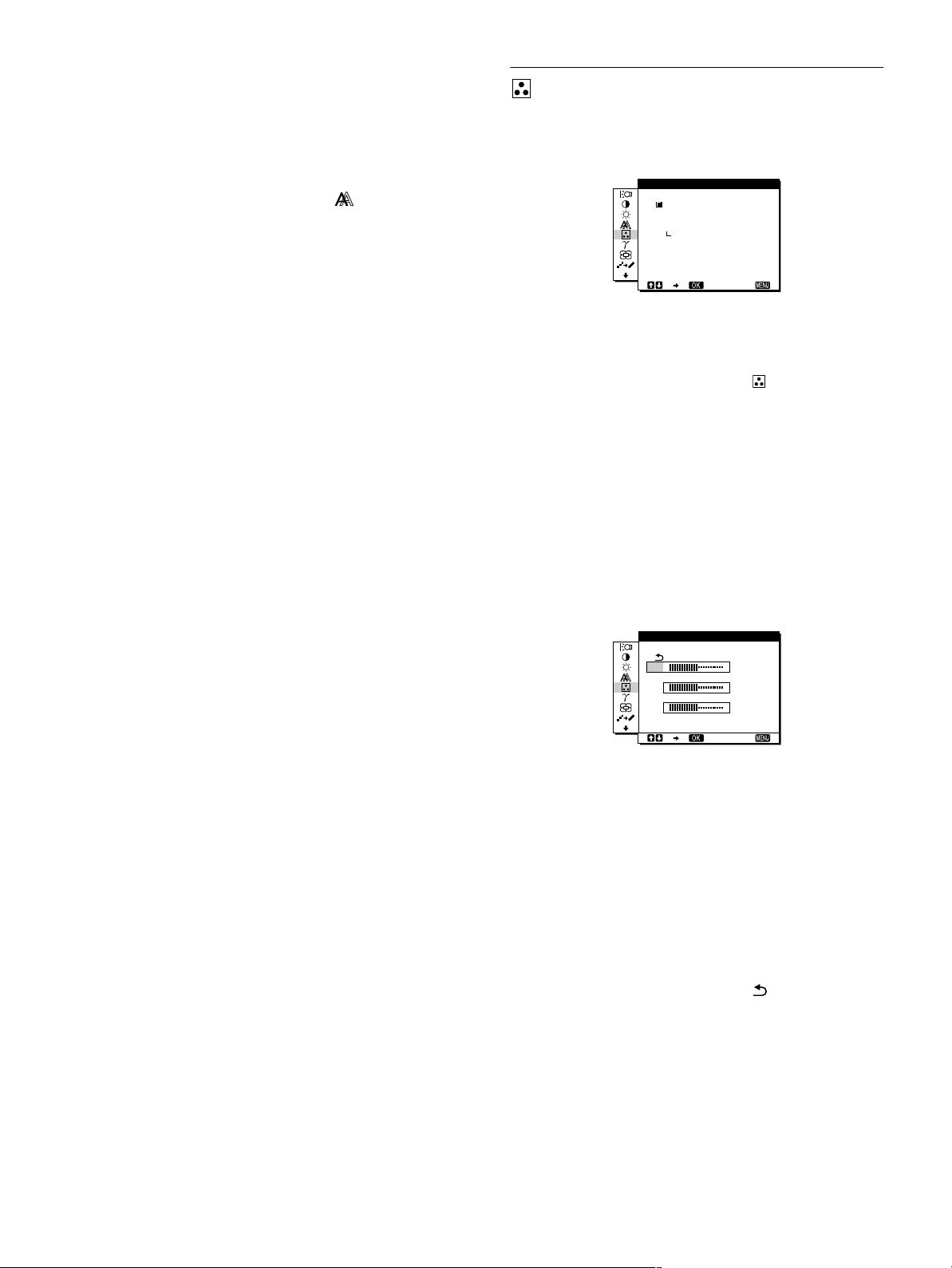
6 Press the M/m buttons to select H CENTER or
V CENTER and press the OK button.
The H CENTER or V CENTER menu appears on the screen.
7 Press the M/m buttons to center the test pattern in
the screen.
8 Click [ END] on the s creen to turn off the test pattern.
9 Pressthe M/m buttonsto select and pressthe OK
button.
Return to the menu screen.
US
9 Press the M/m buttons to select (SCREEN) and
press the OK button.
The SCREEN menu appears on the screen.
10 Pressthe M/m buttonsto selectPITCHand pressthe
OK button.
The PITCH menu appears on the screen.
13
Eliminate a shift of the picture caused by
xxxx
the automatic picture quality adjustment
(AUTO)
1 Press the MENU button.
The main menu appears on the screen.
2 Press the M/m buttons to select (SCREEN) and
press the OK button.
The SCREEN menu appears on the screen.
COLOR
You can select the picture’s color level of the white color field
from the default color temperature settings.
Also, if necessary, you can fine tune the color temperature.
COLOR
9300K
6500K
USER
ADJUST
3 Pressthe M/m buttons to select AUTO and press the
OK button. Then press the M/m buttons to select
OFF and press the OK button.
To resume the automatic picture quality adjustment
function
Select ON in step 3 above.
1280 1024 60Hzx/
EX I T
1 Press the MENU button.
The main menu appears on the screen.
2PresstheM/m buttons to select (COLOR) and
press the OK button.
The COLOR menu appears on the screen.
3PresstheM/m buttons to select the desired color
temperature and press the OK button.
Whites will change from a bluish hue to reddish hue as the
temperature is lowered from 9300K (default setting) to
6500K.
Fine tuning the color temperature
(USER ADJUSTMENT)
INPUT1 and INPUT2 can be set independently.
USER ADJUSTMENT
R
G
B
1280 1024 60Hzx/
50
50
50
EX I T
14
1PresstheM/m buttons to select ADJUST and press
the OK button.
The USER ADJUSTMENT menu appears on the screen.
2PresstheM/m buttons to select R (Red) or B (Blue)
and press the OK button. Then press the M/m
buttons to adjust the color temperature and press
the OK button.
Since this adjustment changes the color temperature by
increasing or decreasing the Rand B components with respect
to G (green), the G component is fixed.
3PresstheM/m buttons to select , then press the
OK button.
The new color setting is stored in memory for USER
ADJUSTMENT and automatically recalled whenever USER
is selected.
The COLOR menu appears on the screen.
GAMMA
SMOOTHING
You can associate the picture’s color shade on the screen with the
picture’s original color shade.
GAMMA
GAMMA 1
GAMMA 2
GAMMA 3
1280 1024 60Hzx/
EX I T
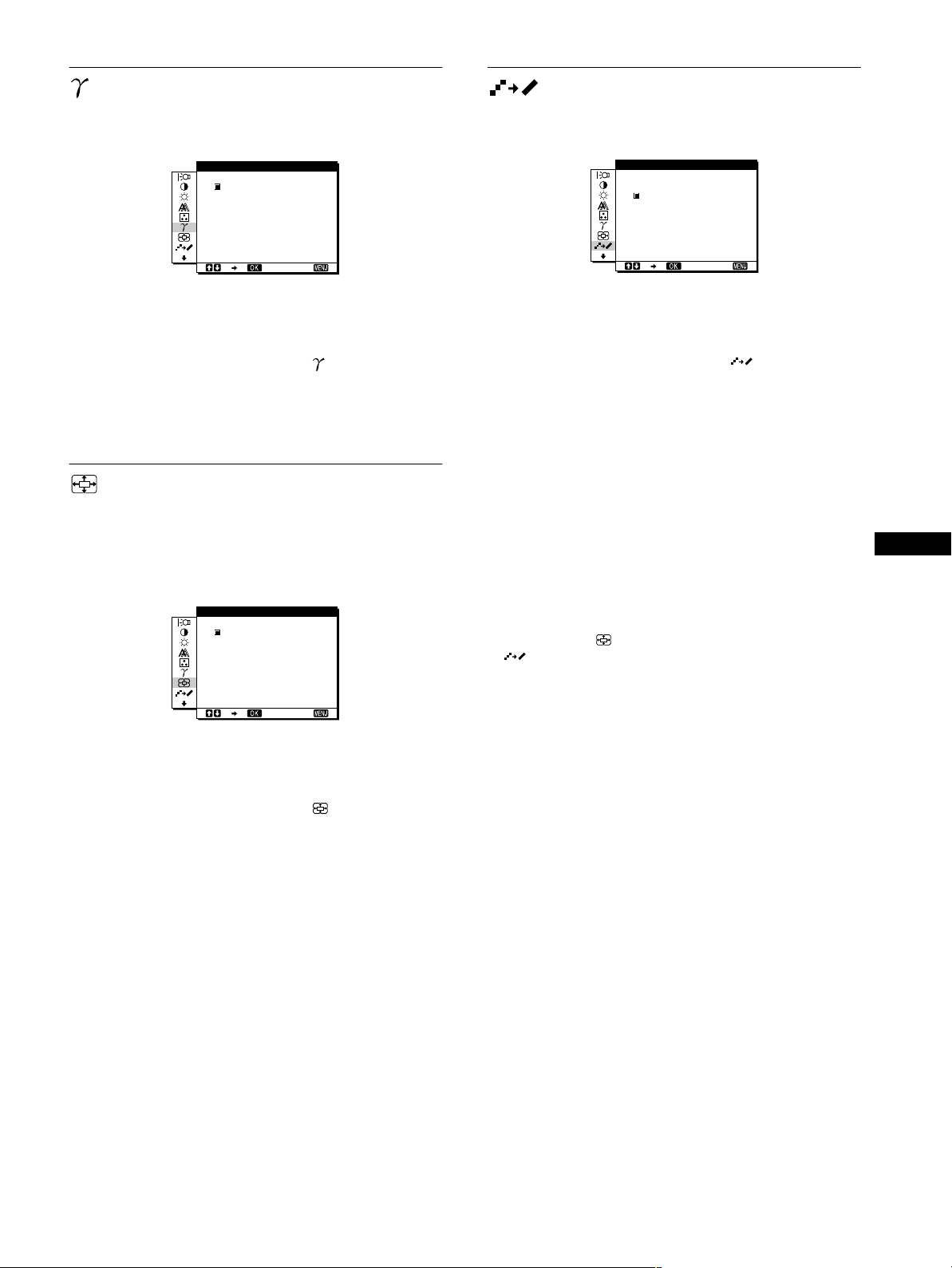
1 Press the MENU button.
The main menu appears on the screen.
2 Press the M/m buttons to select (GAMMA) and
press the OK button.
The GAMMA menu appears on the screen.
3 Press the M/m buttons to select the desired mode.
ZOOM
The monitor is set to display the picture on the screen in full,
irrespective of the picture’s mode or resolution in the default
setting (FULL2).
You can also view the picture in its actual aspect ratio or
resolution.
ZOOM
FULL2
FULL1
REAL
1280 1024 60Hzx/
EX I T
If the picture displayed at the FULL2 or FULL1 mode of ZOOM
is not smooth, use the picture smoothing function.
SMOOTH NGI
TEXT
STANDARD
GRAPH CS
I
1280 1024 60Hzx/
EX I T
1 Press the MENU button.
The main menu appears on the screen.
2 Press the M/m buttons to select (SMOOTHING)
and press the OK button.
The SMOOTHING menu appears on the screen.
3 Press the M/m buttons to select the desired mode.
The smoothing effect becomes stronger in the order of
TEXTtSTANDARDtGRAPHICS.
• TEXT: To make the characters appear clear. (This mode is
suited for text-based applications.)
• STANDARD (The default setting): Standard smoothing
effect.
• GRAPHICS: To make the pictures appear clean. (This
mode is suited for CD-ROM software such as
photo images or illustrations.)
Notes
• When you set the (ZOOM) menu to REAL, the
(SMOOTHING) me nu is not available.
• 1280 × 1024 resolution signals are shown only in REAL mode and
SMOOTHINGis not possible.
US
1 Press the MENU button.
The main menu appears on the screen.
2 Press the M/m buttons to select (ZOOM) and
press the OK button.
The ZOOM menu appears on the screen.
3 Press the M/m buttons to select the desired mode.
• FULL2 (The default setting):Theinputsignalis
displayedon the screen in full, irrespectiveof the
picture’s mode or resolution.
• FULL1: The input signal is displayed on the screen at its
actual aspect ratio. Therefore, black bands may
appear at the top and bottom of the picture
depending on the signal.
• REAL: The input signal is displayed on the screen at its
actual resolution. Sub-1280 × 1024 signals are
displayedat the center of the screen surrounded
by a black frame.
Note
When you use 1280 × 1024 resolution signals, the above mentioned
settings are not available. The picture is displayed on the screen in full.
15
Additional settings
The following menus appear on the screen when you keep
pressing the m button.
• MENU POSITION
• POWER SAVE
ZZ...
• LANGUAGE
• RESET 0
• MENU LOCK
1 Press the MENU button.
The main menu appears on the screen.
2 Keeppressingthe m buttonuntil the desiredmenu’s
item you want to adjust appears on the screen.
3 Press the M/m buttons to select the desired menu
and press the OK button.
Adjust the selected menu according to the following
instructions.
xxxx
MENU POSITION
You can change the menu position if it is blocking an image on
the screen.
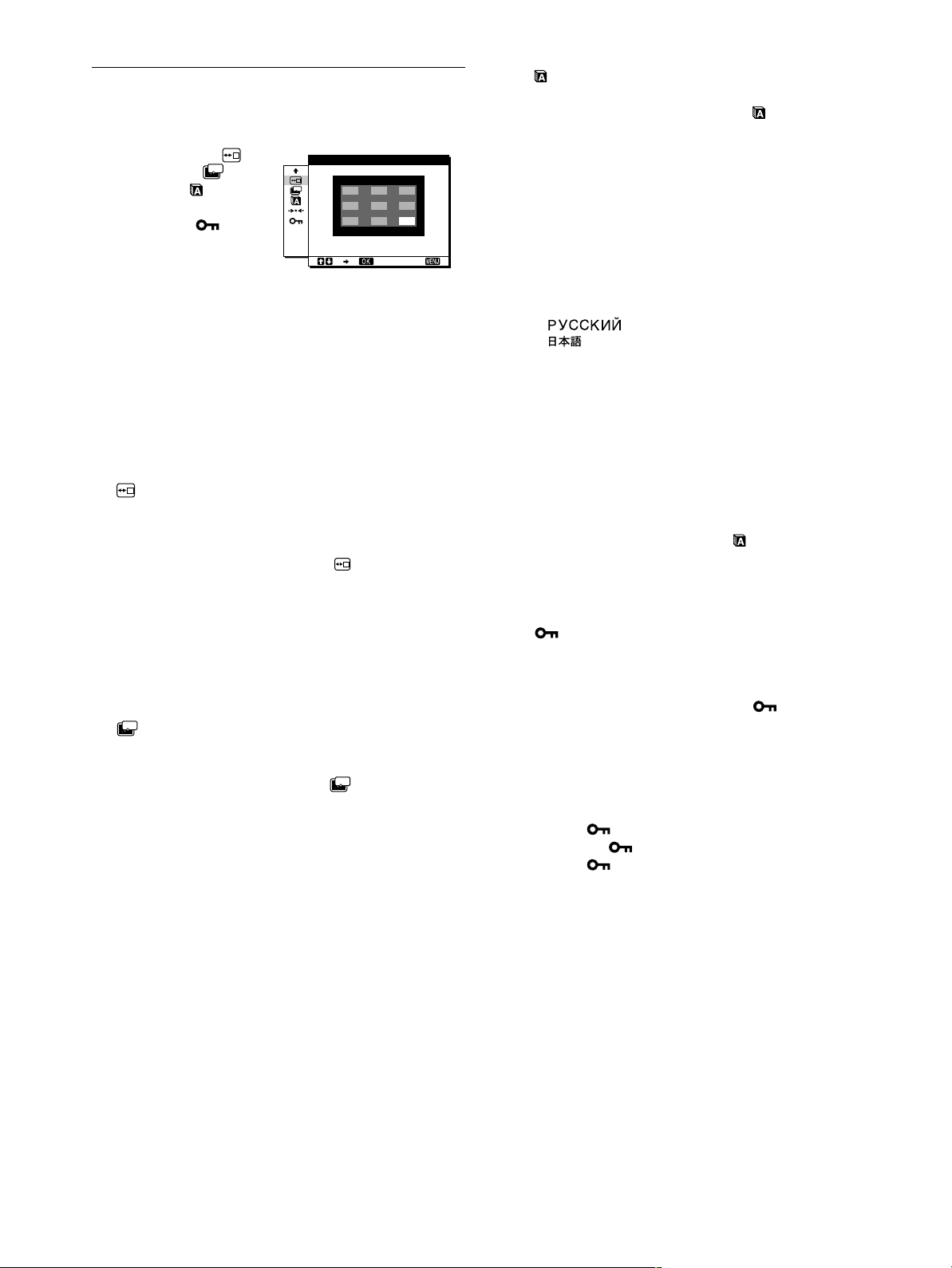
1 Press the M/m buttons to select (MENU
POSITION) and press the OK button.
The MENU POSITION menu appears on the screen.
MENU POS T ONII
ZZ...
1280 1024 60Hzx/
EX I T
LANGUAGE
xxxx
1PresstheM/m buttons to select (LANGUAGE)
and press the OK button.
The LANGUAGE menu appears on the screen.
2PresstheM/m buttons to select a language.
• ENGLISH
• FRANÇAIS:French
• DEUTSCH:German
• ESPAÑOL:Spanish
• ITALIANO: Italian
• NEDERLANDS:Dutch
• SVENSKA:Swedish
• :Russian
• : Japanese
xxxx 0
RESET
Reset the adjustments to the default settings.
1PresstheM/m buttons to select 0 (RESET) and
press the OK button.
The RESET menu a ppears on the screen.
2PresstheM/m buttons to select the desired mode.
• OK: To reset all of the adjustment data to the default
setting. Note thatthe (LANGUAGE) setting
is not reset by this method.
• CANCEL: To cancel resetting and return to the menu
screen.
2 Pressthe M/m buttons to selectthe desired position
and press the OK button.
You can choose one of 9 positions where the menu will
appear.
ZZ...
xxxx
POWER SAVE
Set the power saving mode (page 17).
1 Pressthe M/m buttons to select (POWER SAVE)
ZZ...
and press the OK button.
The POWER SAVE menu appears on the screen.
2 Press the M/m buttons to select either ON or OFF.
• ON: Enters the power saving mode automatically when
no input signal is being input via currently selected
computer.
• OFF: Not enter the power saving mode.
xxxx
MENU LOCK
Lock the control of buttons to prevent accidental adjustments or
resetting.
1PresstheM/m buttons to select (MENU LOCK)
and press the OK button.
The MENU LOCK menu appears on the screen.
2PresstheM/m buttons to select ON or OFF.
• ON: Only the 1 (power) switch and INPUT button will
operate. If you attempt any other operation, the
(MENU LOCK) appears on the screen.
• OFF: Set (MENU LOCK) to OFF. If you set the
(MENU LOCK) to ON, only this menu item
can be selected.
16
Technical Features
Power saving functi on
This monitor meets the power-saving guidelines set by VESA,
NERGYSTAR, and NUTEK. If the monitor is connected to a
E
computer or video graphics board that is DPMS (Display Power
Management Signaling) compliant, the monitor will
automatically reduce power consumption as shown below.
Power mode Power consumption1(power)
normal
operation
active off*
(deep sleep)**
1 (power) off 1 W red
main power off 0 W off
* Whenyour computer enters the “active off” mode, the input signal is
cut and NO INPUT SIGNAL appears on t he screen. After 20 seconds,
the monitor enters the power saving mode.
** “Deep sleep” is a power saving mode defined by the Environmental
Protection Agency.
Note
ZZ...
If the (POWER SAVE) is set to OFF (page 16), the monitor does not
enter the power saving mode.
58 W (max.) green
3 W (max.) orange
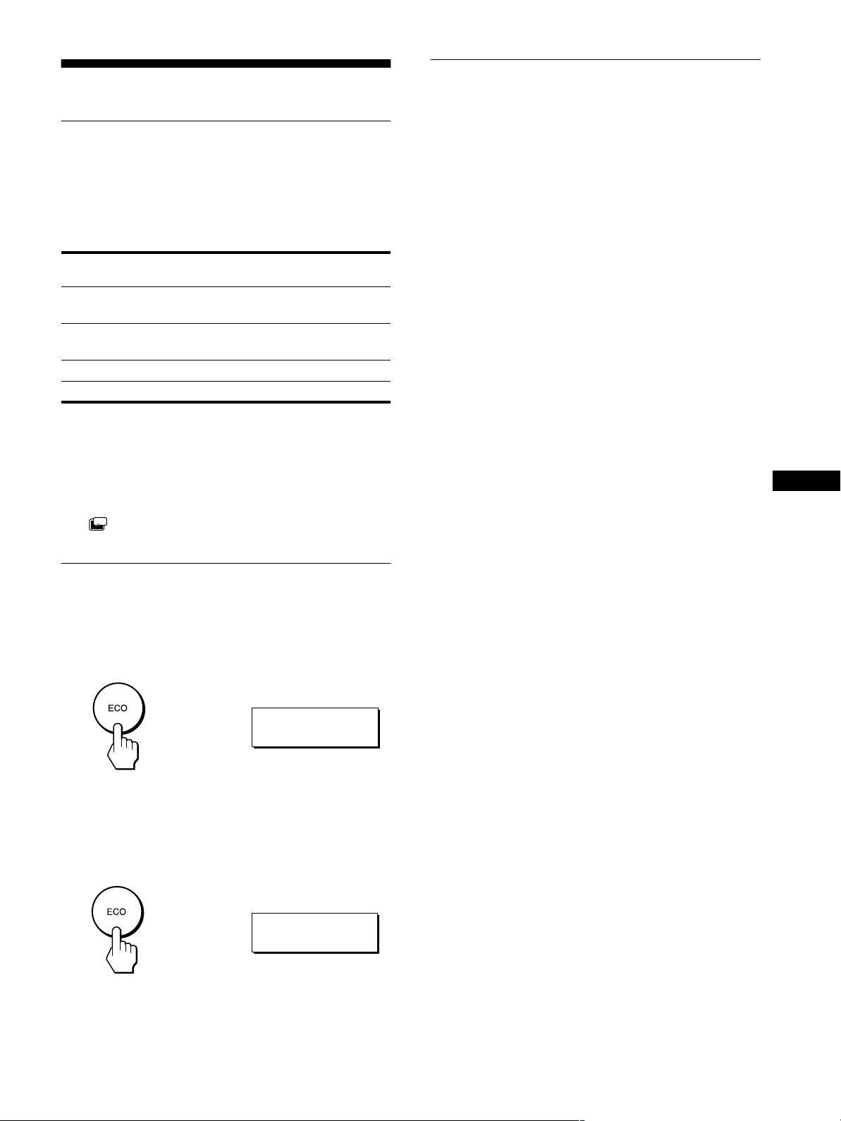
Reducing the power consumption
(ECO mode)
If you press the ECO button on the front of the monitor, the
backlight level reduces and the power consumption is reduced.
Press the ECO button.
,
indicator
:
ECO ON
Automatic picture quality
adjustment function
signal only)
When the monitor receives an input signal, it
automatically adjusts the picture’s position and
sharpness(phase/pitch),and ensuresthat a clear
picture appears on the screen.
The factory preset mode
When the monitor receives an input signal, it automatically
matches the signal to one of the factory preset modes stored in the
monitor’s memory to provide a high quality picture a t the center
of the screen. If the input signal matches the factory preset mode,
the picture is appears on the screen automatically with the
appropriate default adjustment.
If input signals do not match one of the factory
preset modes
When the monitor receives an input signal, the automatic picture
quality adjustment function of this monitor is activated and
ensures that a clear picture always appears on the screen (within
the following monitor frequency ranges):
Horizontal frequency:28 – 92 kHz
Vertical frequency: 56 – 85Hz
Consequently, the first time the monitor receives input signals
that do not match one of the factory preset modes, the monitor
may take a longer time than normal for displaying the picture on
the screen. This adjustment data is automatically stored in
memory so that next time, the monitor will function in the same
way as when the monitor receives the signals that match one of
the factory preset modes.
If y ou adjust the phase, pitch, and pictures
position manually
For some input signals, the automatic picture quality adjustment
function of this monitor may not completely adjust the picture
position,phase, and pitch. Inthis case, you can manually setthese
adjustments (page 12). If you manually set these adjustments,
they are stored in memory as user modes and automatically
recalled whenever the monitor receives the same input signals.
(analog RGB
US
The ECO: ON menu appears on the screen and the backlight level
is reduced. The menu automatically disappears after about 5
seconds.
To cancel the ECO mode
Press the ECO button again.
,
The ECO: OFF menu appears on the screen and normal backlight
level is set. The menu automatically disappears after about 5
seconds.
:
ECO OFF
17
Troubleshooting
Before contacting technical support, refer to this section.
On-screen messages
If there is something wrong with the input signal, one of the
followingmessages appears on the screen. To solve the problem,
see “Trouble symptoms and remedies” on page 19.
If CABLE DISCONNECTED appears on the screen
This indicates that the video signal cable has been disconnected
from the currently selected connector.
INFORMATION
CAB L E D I SCONNECTED
INPUT1 :DVI -D
GO TO POWER SAVE
If OUT OF SCAN RANGE appears on the screen
This indicates that the input signal is not supported by the
monitor’s specifications. Check the following items.
For more information about on-screen messages, see “Trouble
symptoms and remedies” on page 19.
INFORMATION
OUT OF SCAN RANGE
INPUT1 :DVI -D
xxx.xkHz/ xxx.xHz
If “xxx.x kHz/xxx Hz” is displayed
This indicates that either the horizontal or vertical frequency
is not supported by the monitor’sspecifications.
The figures indicate the horizontal and vertical frequencies of
the current input signal.
If “RESOLUTION > 1280 × 1024” is displayed
This indicates that the resolution is not supported by the
monitor’s specifications (1280 × 1024 or less).
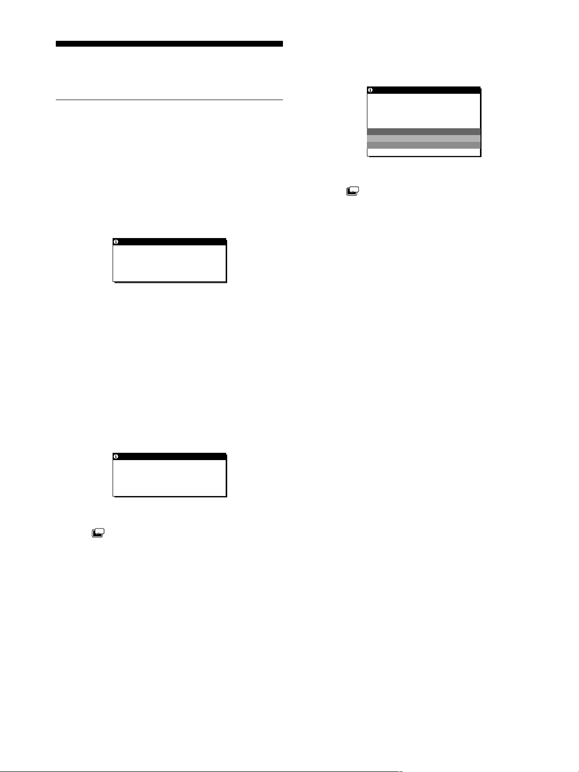
If NO INPUT SIGNAL appears on the screen
This indicates that no signal is being input via the currently
selected connector.
GO TO POWER SAVE
ZZ...
If the (POWER SAVE) is set to “ON,” the monitor will
enter the power saving mode after about 5 seconds from the
time the message is displayed.
INFORMATION
NO INPU T S I GNA L
INPU T1 :DV I -D
GO TO POWER SAVE
GO TO POWER SAVE
ZZ...
If the (POWER SAVE) is set to “ON,” the monitor will
enter the power saving mode after about 5 seconds from the
time the message is displayed.
18

Trouble symptoms and remedies
If a problem occurs as a result of aconnected computer or other equipment, refer to the connected computer/equipment’s instruction manual.
Use the self-diagnosis function (page 21) if the following recommendations do not resolve the problem.
Symptom Check these items
No picture
If the 1 (power) indicator is not lit,
or if the 1 (power) indicator will not
light up when the 1 (power) switch
is pressed,
The 1 (power) indicator turns on
red.
If the 1 (power) indicator is green, • Use the self-diagnosis function (page 21).
If CABLE DISCONNECTED
appears on the screen,
If NO INPUT SIGNAL appears on
the screen, or the 1 (power)
indicator is orange,
If OUT OF SCAN RANGE appears
on the screen (page 18),
If using Windows, • If you replaced an old monitor with this monitor, reconnect the old monitor and do the
If using a Macintosh system, • When connecting a Macintosh computer, use an adapter (not supplied) if necessary.
• Check that the power cord is properly connected.
• Check that the monitor’s MAIN POWER switch is “on” (page 9).
• Check that the 1 (power) switch is on.
• Check that the video signal cable is properly connected and all plugs are firmly seated in
their sockets (page 7).
• Check that the video input connector’s pins are not bent or pushed in.
• Check that the input select setting is correct (page 11).
• A non-supplied video signal cable is connected. If you connect a non-supplied video
signal cable, CABLE DISCONNECTED may appear on the screen before entering the
power saving mode. This is not a malfunction.
• Check that the video signal cable is properly connected and all plugs are firmly seated in
their sockets (page 7).
• Check that the video input connector’s pins are not bent or pushed in.
• Check that the input select setting is correct (page 11).
xProblem caused by a connected computer or other equipment, and not
caused by the monitor
• The computer is in the power saving mode. Try pressing any key on the keyboard or
moving the mouse.
• Check that your graphics board is attached to the computer properly.
• Check that the computer’spoweris“on.”
xProblem caused by a connected computer or other equipment, and not
caused by the monitor
• Check that the video frequency range is within that specified for the monitor. If you
replaced an old monitor with this monitor, reconnect the old monitor and adjust the
computer’s graphics board in the following ranges:
Horizontal frequency: 28 – 92 kHz
Vertical frequency: 56 – 85 Hz
Resolution: 1280 × 1024 or less
following. Select “SONY” from the “Manufacturers” list and select “SDM-P82” from the
“Models” list in the Windows device selection screen. If “SDM-P82” does not appear in
the “Models” list, try “Plug & Play” or install the information file for this monitor using
the Windows Monitor Information Disk.
Connect the adapter to the computer before connecting the video signal cable.
US
(continued)
19

Symptom Check these items
Picture flickers, bounces,
oscillates, or is scrambled.
• Adjust the pitch and phase (analog RGB signal only) (page 12).
• Isolate and eliminate any potential sources of electric or magnetic fields such as other
monitors, laser printers, electric fans, fluorescent lighting, or televisions.
• Move the monitor away from power lines or place a magnetic shield near the monitor.
• Try plugging the monitor into a different AC outlet, preferably on a different circuit.
• Change the orientation of the monitor.
xProblem caused by a connected computer or other equipment, and not
caused by the monitor
• Check your graphics board manual for the proper monitor setting.
• Confirm that the graphics mode (VESA, Macintosh 19'' Color, etc.) and the frequency of the
input signal are supported by this monitor. Even if the frequency is within the proper range,
some graphics boards may have a sync pulse that is too narrow for the monitor to sync correctly.
• This monitor does not process the interlace signals. Set for progressivesignals.
• Adjust the computer’s refresh rate (vertical frequency) to obtain the best possible picture
(60 Hz is recommended).
Pictureisfuzzy. • Adjust the brightness and contrast (page 12).
• Adjust the pitch and phase (analog RGB signal only) (page 12).
xProblem caused by a connected computer or other equipment, and not
caused by the monitor
• Set the resolution to 1280 × 1024 on your computer.
Pictureisghosting. • Eliminate the use of video cable extensions and/or video switch boxes.
• Check that all plugs are firmly seated in their sockets.
Picture is not centered or sized
properly (analog RGB signal only).
• Adjust the pitch and phase (page 12).
• Adjust the picture position (page 13). Note that some video modes do not fill the screen to
the edges.
Pictureistoosmall. • Set the zoom setting to FULL2 (page 15).
xProblem caused by a connected computer or other equipment, and not
caused by the monitor
• Set the resolution to 1280 × 1024 on your computer.
Pictureisdark. • Adjust the brightness (page 12).
• Adjust the backlight (page 12).
• It takes a few minutes for the display to become bright after turning on the monitor.
• Adjust (GAMMA)(page 15).
• If you press the ECO button, the screen turns darker.
Wavy or elliptical pattern (moire)
• Adjust the pitch and phase (analog RGB signal only) (page 12).
is visible.
Color is not uniform. • Adjust the pitch and phase (analog RGB signal only) (page 12).
White does not look white. • Adjust the color temperature (page 14).
Monitor buttons do not operate
• IfthemenulockissettoON,setittoOFF(page16).
( appears on the screen).
The monitor turns off after a while. • SetthepowersavingfunctiontoOFF(page16).
xProblem caused by a connected computer or other equipment, and not
caused by the monitor
• Set the computer’s power saving setting to off.
Displaying this monitor’s name, serial number,
and date of manufacture.
While the monitor is receivinga videosignal, pressand
hold the MENU button for more than 5 seconds.
The monitor’s information box appears. Press the MENU button
againtomaketheboxdisappear.
Example
MENU
INFORMATION
MODEL : SDM-P82
SER. NO : 1234567
MANUFACTURED : 2002-40
Model
name
Serial
number
Week and year of
manufacture
20
If any problem persists, call your authorized Sony dealer and give
the following information:
• Model name: SDM-P82
• Serial number
• Name and specifications of your computer and graphics board.
• Type of input signals (analog RGB/digital RGB)
 Loading...